Article

Ranking of Injection Biochar for Slag Foaming Applications in Steelmaking

1
CanmetMATERIALS, Natural Resources Canada, 183 Longwood Road South, Hamilton, ON L8P 0A5, Canada
2
CanmetENERGY, Natural Resources Canada, 1 Haanel Drive, Ottawa, ON K1A 1M1, Canada
*
Author to whom correspondence should be addressed.
Metals 2023, 13(6), 1003; https://doi.org/10.3390/met13061003
Submission received: 5 May 2023 / Revised: 10 May 2023 / Accepted: 19 May 2023 / Published: 23 May 2023
(This article belongs to the Special Issue Low-Carbon Metallurgy Technology towards Carbon Neutrality)

Abstract

:
The electric arc furnace (EAF) has the potential to significantly contribute to the decarbonization of the iron and steel industry. However, during EAF steelmaking, carbon still needs to be injected into the molten slag to initiate slag foaming, which is beneficial to the energy efficiency and protection of the furnace. To move away from fossil carbon, biocarbon has gained attention as an injection carbon agent. In this study, two biochar candidates were added to the molten slag layer of an induction furnace for steel melting, to simulate EAF steelmaking conditions. The resultant slag foaming height was measured, and a ranking in comparison to two fossil carbon candidates was developed. The results indicate that the injection biochar sample, in the form of a bio-briquette, has a considerable degree of slag foaming capacity. More work is ongoing to develop a standardized testing methodology of ranking various injection biochar candidates for their suitability and qualification for use on a larger scale.

1. Introduction

Iron and steelmaking are energy intensive processes that rely on fossil fuels to meet energy demands and also for the primary extraction and refining of ores [1,2]. Therefore, the iron and steelmaking industry is one of the largest emitters of CO2, with average emissions of ~2.0 tons of CO2 per ton of steel produced [3]. The global production of steel has dramatically increased over the last several decades, and this is expected to continue as steel market demand is tied to population and economic growth [4]. Therefore, to address the growing issue of greenhouse gas emissions, steelmakers face the challenge of decarbonizing the steel industry and developing new technologies for the sustainability and reduction in CO2 emissions.
There are two well-established technologies used in steelmaking, which are the blast furnace–basic oxygen furnace (BF-BOF) and the electric arc furnace (EAF). Presently, the BF-BOF accounts for most (70.7%) of the steelmaking in the world [5]. However, the low CO2 emission potential of EAF steelmaking has heightened interest in this method in recent years, as decarbonization has become the focus of the steel industry [6]. An EAF functions by passing a current through graphite electrodes to create arcs that act as the primary heating source. EAF is primarily used for recycling scrap steel, as well as for other materials such as direct reduced iron, hot briquetted iron, or pig iron. Additionally, carbon material is also included in the charge materials to consume excess oxygen during melting and to supply supplementary chemical heat. Carbon material is also injected into the molten slag during EAF operation to generate a slag foam layer, which increases energy efficiency, protects the furnace lining, and decreases noise and electrode consumption [7].
Injection carbon is a critical component for efficient EAF steelmaking due to the benefits of slag foaming. The carbon will oxidize and reduce the iron oxides, generating a large number of bubbles, which results in slag foaming and some recovery of the iron. The kinetics of the slag/carbon reaction have been studied [8,9] and can be described with the following steps. First, metal oxides form in the melt, creating the slag layer; the iron oxides and solid carbon react to form liquid iron and CO (Equation (1)); a gas film is formed around the solid carbon, and the reaction proceeds via two sequential reactions, with CO-CO2 acting as gaseous intermediates (Equations (2) and (3)); and the interaction between the slag and the CO/CO2 gas products create a gas/liquid foam.
(FeO) + Cs → Fe + CO
(FeO) + CO → Fe + CO2
Cs + CO2 → 2 CO
Theoretically, the main parameter for a good foaming effect is reactivity, and thus a high carbon content and a low ash content of the carbon source. Fossil fuel sources of carbon are typically used as injection and charge carbons in the EAF process [10]. One of the available measures to decrease CO2 emissions from EAF steelmaking involves switching from the use of fossil fuels to solid biochar produced from biomass for injection carbon. The CO2 generated by using solid biochar can be absorbed during the growth of biomass, and thus biochar can be considered as a carbon neutral material and does not emit additional CO2 into the atmosphere. Previous work has shown that a 60% replacement of fossil fuel charge and injection carbon can result in a 19% total decrease in CO2 emissions [11].
Despite biochar presenting great potential to reduce CO2 emissions from the process, research focused on the use of biochar to replace fossil fuels in EAF steelmaking has been limited. Kieush et al. [12] compared the physical, chemical, and structural properties of fossil carbon and biochar. It was determined that biochar had limited use due to its low fixed carbon value. Fidalgo et al. [13] examined the thermal behavior of biochar from agricultural wastes at heating rates typical of injecting carbon into an EAF. The authors found that biochar showed different thermal behavior, with grapeseed biochar showing higher combustion and gaseous reactivities. Therefore, it was proposed to be suitable for injection carbon substitution. It should be noted that the concept of using grapeseed biochar as an injection carbon in EAF was not experimentally validated by a slag and biochar interaction. Huang et al. [14] studied the reaction behavior of biochar and fossil carbon materials using a Tensiometer sessile drop test on synthetic EAF slag at 1600 °C. It was concluded, based on the measured contact angles and interaction behavior, that the biochar materials were the least reactive compared to other carbon sources. However, in industrial operations, slag is in excess compared to injected carbon, which is the opposite of that for the Tensiometer test. Moreover, in the Tensiometer test, the contact between the carbon particle and slag was static, meaning that the contact surface may not continuously evolve. Therefore, the Tensiometer experimental set up may not be representative of an industrial EAF injection operation. Few studies have examined the use of injecting biochar directly in a simulated steelmaking process. Demus et al. [15] used biogenic briquettes agglomerated from various mixtures of biochar as the charge carbon in pilot EAF trials, and no negative impact was detected on the off-gas, slag, and steel chemistry. Bianco et al. [11,16] reported on slag foaming behavior at a laboratory scale by melting a mixture of biochar and EAF slag. The change in slag volume was monitored by a camera from overhead, and afterwards slag heights from the crucible were qualitatively reported. It was found that the grapeseed biochar showed general suitability based on its high slag foaming capacity compared to coal. Testing was extended to a pilot scale EAF, where differences in the reaction sequence were detected and attributed to the differences in reactivity, carbon content, and physical properties of the biochar compared to fossil charge coal. Nonetheless, no difference in steel quality was detected [17]. Overall, the present literature shows the validity of some biochar candidates’ usage in EAF steelmaking. However, there are conflicting reports and incomplete observations on the effectiveness of injection biochar for slag foaming. Furthermore, there has been limited research observing the effect of carbon additions to a bath of molten slag and steel, which is a more accurate simulation of injection carbon. Therefore, there is a general need for an injection biochar testing methodology to rank its slag foaming capacity relative to existing injection carbon sources.
Slag foaming studies have focused on two major aspects: the reaction kinetics of carbonaceous materials, and the effects of slag properties. In this study, a series of melting experiments was conducted to isolate the effect of injection carbon type on slag foaming. This work explores the application of biochar as an injection carbon and determines a methodology to rank injection carbon materials by measuring increases in the slag foam height. Two biochar materials were studied, along with metallurgical coke and industrial injection carbon as references cases. The other variables were kept constant, including the slag material, steel composition, furnace dimension, heating profile, and maximum temperature. Using an induction furnace to simulate EAF steelmaking, carbon was added to the molten slag layer on a steel melt to mimic injection carbon in industrial operations. The results were compared across injection carbon types, and a viable method for injection carbon ranking and laboratory scale testing was developed.

2. Materials and Methods

2.1. Materials

Four different carbon types were used as injection carbon: nut coke, industrial injection carbon (IIC), loose biochar pellets, and bio-briquette. The IIC and nut coke are fossil fuel sources of carbon and were used as reference cases in this study. The loose biochar pellets and bio-briquette were the biomass-based carbon sources. The loose biochar was 100% biochar produced following slow pyrolysis of Pine softwood sawdust at 475 °C, and the bio-briquette was produced by densification of Black Spruce softwood biochar and bio-oil. The proximate and ultimate analysis of the different injection carbon samples are provided in Table 1. As shown, the chemical compositions of the four carbon candidates are significantly different. The sulfur content of biochar samples is much lower than the fossil fuel samples, particularly the IIC, indicating their environmental advantage. While the biochar samples’ oxygen content is higher relative to nut coke and IIC, their carbon content is consequently reduced. To better examine the effect of ash on the slag foaming behavior, ash compositions were also analyzed. The ash basicity of bio-briquette was extremely high in comparison to the other three samples. Additionally, there were other minor components as well as the loss of fusion not listed in Table 1. For the charge material, 20 kg of steel (0.2% C, 0.8% Mn, 0.2% Si) and 1.13 kg of industrially sourced EAF slag (23.0% FeO, 39.0% CaO, 14.0% SiO2, 10% MgO, 8.0% Al2O3) was used in each experimental trial.

2.2. Scanning Electron Microscope Analysis

The four injection carbon samples were characterized using scanning electron microscope (SEM) images and energy dispersive X-ray spectroscopy (EDS). All SEM and EDS characterization work was performed at CanmetMATERIALS using Nova NanoSEM-650. EDS spectra on specific areas were collected under 20 keV acceleration voltage, and semi-quantitative composition calculations were performed using EDAX Genesis software.

2.3. TGA Reactivity Analysis

The reactivity of carbon samples with air and CO2 was evaluated using a Netzsch STA 449 F3 Jupiter thermogravimetric analysis (TGA) instrument. Carbon samples were crushed to less than 60 mesh (250 µm) to eliminate the effect of sample particle size on the measurement result. The prepared sample was loaded into a 0.2 mL crucible and then into the TGA equipment. The sample temperature was increased from room temperature to 1100 °C at 10 °C/min under air/CO2 gas atmosphere to analyze reactivity. The carbon sample was allowed to react with air or CO2 and the sample weight was continuously monitored. The air/CO2 gas flowrate was maintained at 20 mL/min.

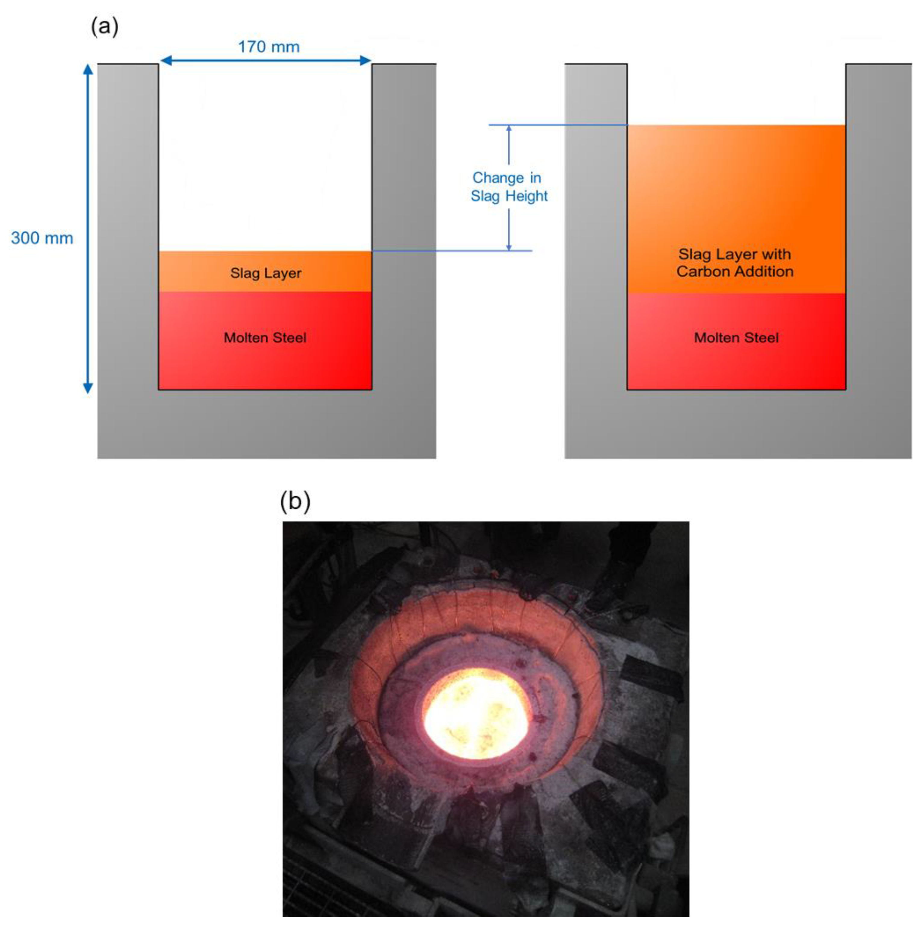
2.4. Experimental Set-Up and Method

To simulate EAF steelmaking at a laboratory scale, a 100 kW induction furnace with a 50 kg steel capacity and 170 mm inner diameter of alumina crucible (90% Al2O3 and 10% SiO2) was used for the melting and foaming experiments. A steel charge of 20 kg was prepared and melted down. When the steel melt reached a temperature in a range of 1620 to 1650 °C, 1.13 kg of EAF slag was added to the steel melt to make a layer of molten slag. The temperature was measured using an S-type thermocouple tip. The injection carbon samples were added to the melt in batches every 6 s for 60 s. Injection carbon samples were packaged in copper packets and charged onto the surface of the melt. Ten packets (6 g carbon per packet) of injection carbon were plunged into the molten slag. To ensure penetration, the slag and carbon sample were mixed thoroughly and quickly once the packet had been dropped. This experimental set-up to simulate EAF steelmaking was developed based on the previous work by Ji et al. [18]. Figure 1a shows a schematic of the experimental set-up and slag foaming, and Figure 1b shows an image of the furnace that was used.
The initial steel melt height and the depth of the molten slag were measured using a steel rod from the furnace surface. After the carbon addition, the slag height was measured in increments of approximately 5 min for a total of 20 min. The change in slag height is an indication of slag foaming. The maximum slag foaming was defined as the maximum percentage change in the slag height and was used to rank the injection carbon types. Additionally, the change in slag height over time was also used to study the injection carbon samples’ slag foaming response.

3. Results and Discussions

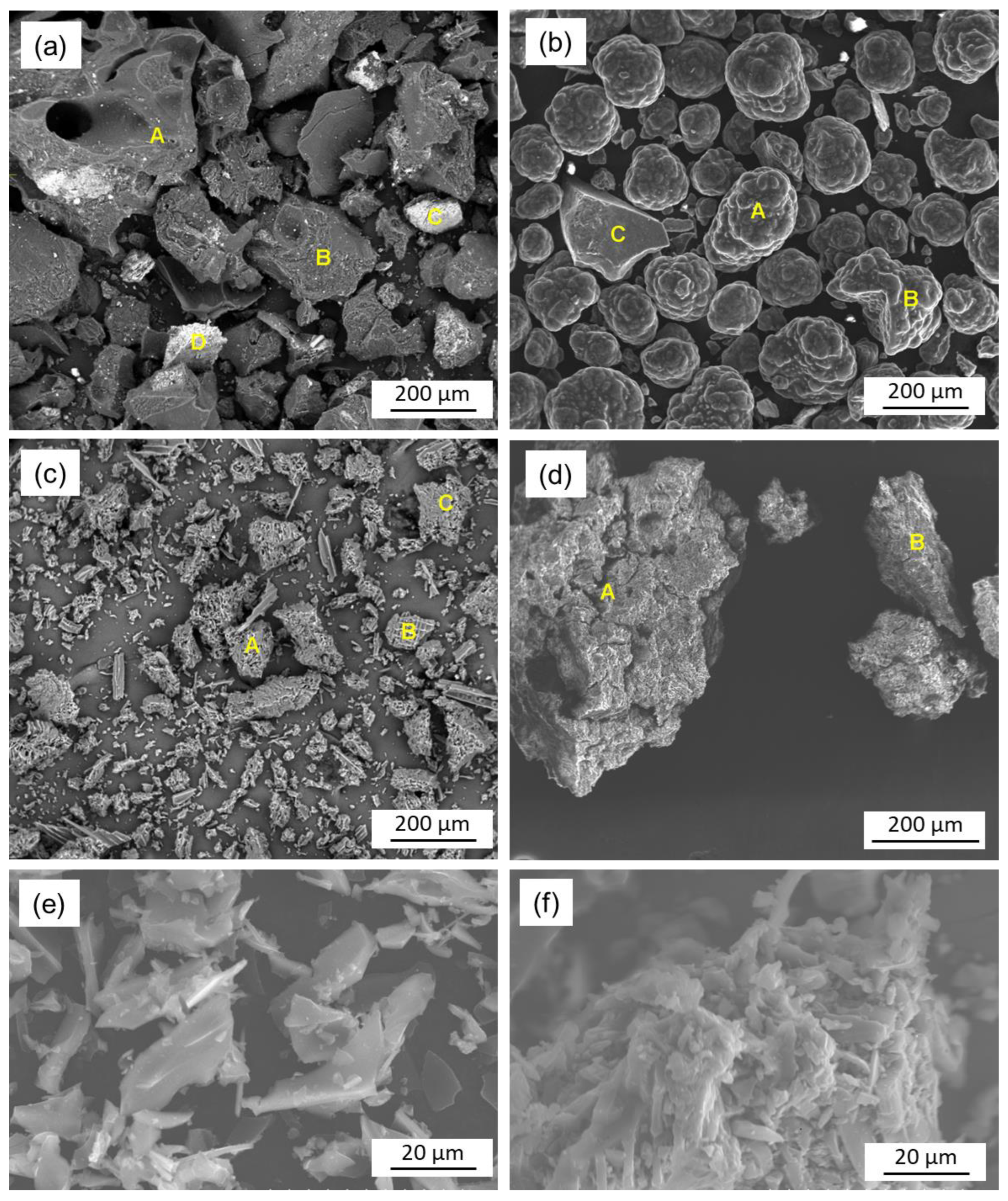
3.1. Surface Morphology Analysis

High magnification SEM images of the injection carbon samples are shown in Figure 2. The bio-briquette samples were crushed into small pieces for SEM analysis. Each injection carbon type showed a different surface morphology. The morphology of the nut coke particles is shown in Figure 2a. The particles mostly had a cubic structure, with a mixture of smooth and rough surfaces. Figure 2b shows the appearance of IIC sample, which appear to have a smooth surface and a spherical shape without any sharp angles. However, there is a particle with a cubic shape like the nut coke particles in the image. The loose biochar in Figure 2c has a woody cellular appearance with many fine particles. The particles appear to have a smooth surface, although there is considerable porosity and a layered structure. In Figure 2d, the bio-briquette particles are shown. The surface appears to be rough and contains less porosity. The pores were either filled with smaller particles or squeezed during the densification process. To clearly show their structures, high magnification images of the loose biochar and bio-briquette are shown in Figure 2e and Figure 2f, respectively.
EDS point scans were also completed at various locations on each injection carbon sample. The locations of the point scans are indicated in Figure 2 by letters in their sequential order. The results are summarized in Table 2. The EDS measurements of carbon and oxygen content gave a semi-quantitative measurement that could be compared among the injection carbon types. It should be noted this was used as a relative measurement for comparison. Both biochar samples (bio-briquette and loose biochar) had relatively higher oxygen content compared to the fossil fuel injection carbon samples. Relatedly, the carbon content was also relatively lower. A high sulfur content was also detected in the IIC sample, which was a distinct characteristic compared to the other three samples. The results aligned well with the results provided from chemical composition analysis, as shown in Table 1.
The SEM analysis shows obvious distinctions among the injection carbon types. Differences were detected in both morphological characteristics and chemical composition, which may influence the slag foaming performance. Given that the interaction of these factors on slag foaming is very intricate, and the focus of this work is on the application and ranking of injection carbon, the mechanistic roles will not be explored in detail here. However, it is important to note different features, since detecting their impact on slag foaming performance is an objective of the ranking methodology in this work.

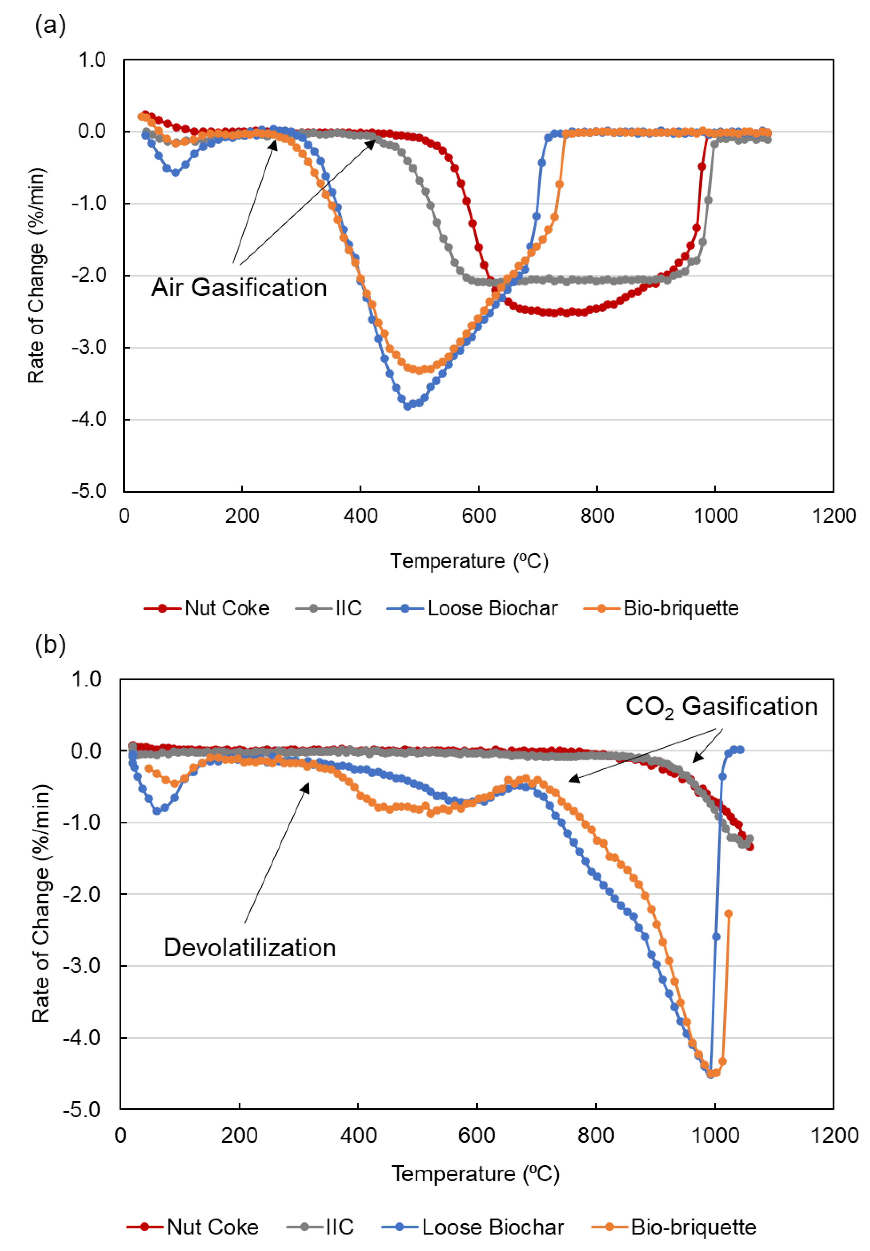
3.2. Reactivity with Air and CO2

The reactivity of the carbon samples was assessed in the TGA apparatus, as mentioned in Section 2.3, using non-isothermal methods. Figure 3 reports the results for the determinations of mass change rates due to the reaction with air and CO2. The initial gasification temperatures were also determined, and are shown in Table 3.
As expected, the loose biochar and bio-briquette samples present higher air reactivities in comparison to the nut coke and IIC samples, with much lower initial air reaction temperatures, at 303 °C and 274 °C vs. 502 °C and 426 °C, respectively, as shown in Table 3. The releasing of volatile matter (VM) in the four samples was not detected in the reactivity test under an air atmosphere. However, the devolatilization can be clearly observed for loose biochar and bio-briquette samples with a CO2 atmosphere, as shown in Figure 3b. The initiation of the devolatilization of the two samples occurred at a similar temperature of about 350 °C. The VM content in the bio-briquette is relatively high, at 31%, as shown in Table 1. The steeper mass change rate of the bio-briquette is an indication of the higher VM content, which is in alignment with the composition analysis. Bio-oil was used as a binder in the densification process to produce the bio-briquette. The high VM content in the bio-oil increased the VM in the resultant bio-briquette. Similar to the results of the air reactivity tests, the biochar and bio-briquette started to react with CO2 at lower temperatures compared to the nut coke and IIC, as shown in Figure 3.
When injected into an EAF furnace, the high reactivities of the biochar samples may result in the combustion of the samples before they reach the slag layer. To counter this issue, a special injection lance to prevent early combustion can be designed, or a submerged injection will remedy this problem. Additionally, the high reactivities of the biochar samples with air and CO2 may indicate that their reactivities with FeO are elevated.

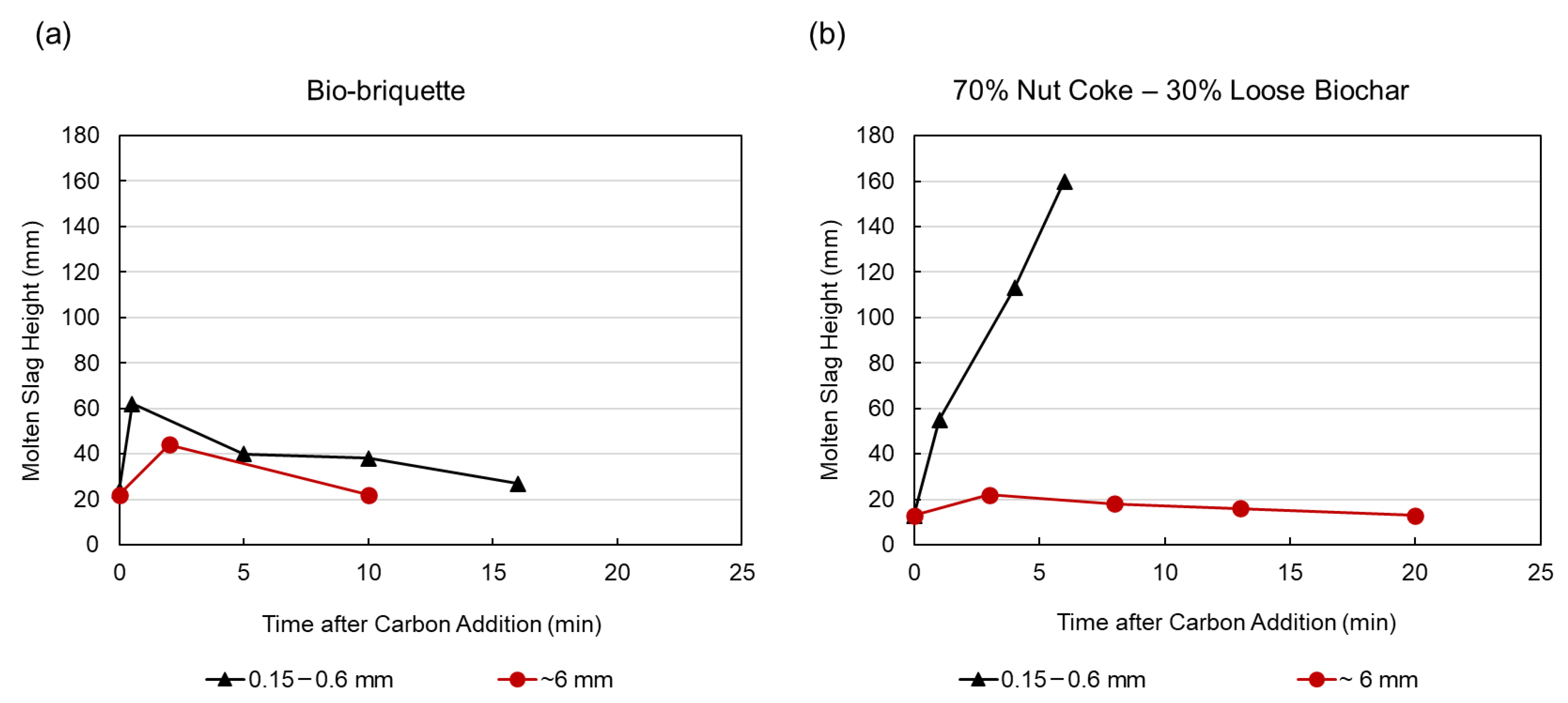
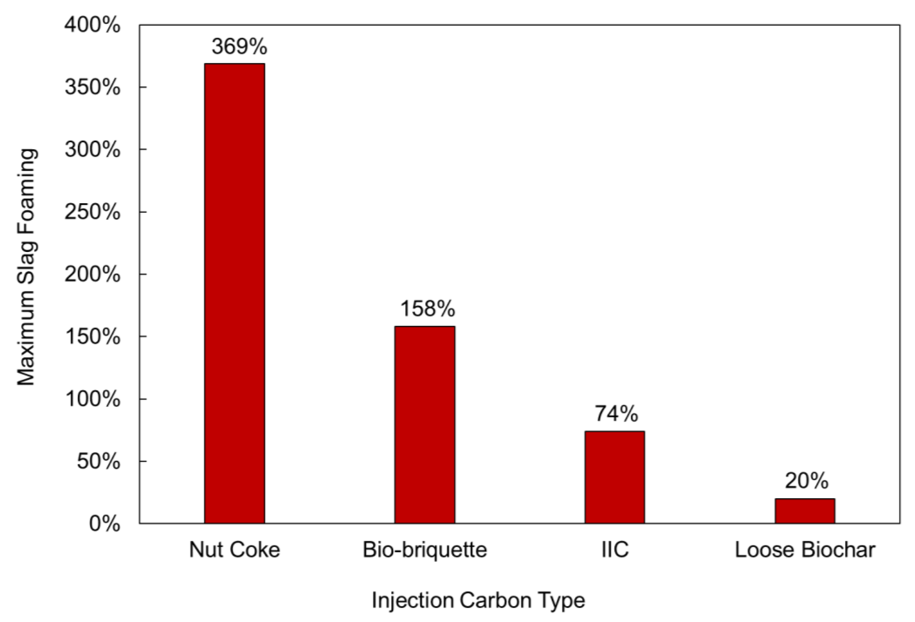
3.3. Slag Foaming Measurements

The four injection carbonaceous materials were tested for their maximum slag foaming height. The results are shown in Figure 4. It can be clearly seen that the nut coke exhibited the highest maximum slag foaming. Within 5 min after charging the nut coke sample, the slag layer had grown 369%, and reached the content capacity of the furnace before another height measurement could be taken. This finding supported the effective and rapid reaction between slag and the nut coke sample. The bio-briquette sample also appeared effective for slag foaming, but to a lesser degree than the nut coke sample. After 0.5 min, the slag reached its maximum foaming at 158% and slowly decreased back to the original slag height over the course of 16 min (see Figure 5). The rapid foaming may be attributed to the releasing of VM from the bio-briquette sample to the molten slag layer, consequently foaming the slag. Once the devolatilization had been completed, the slag height reduced since there was not a continuous supply of VM and volatile gas is ineffective at maintaining the foam [19]. Conversely, the IIC and loose biochar did not perform as well. The IIC reached 74% maximum slag foaming, which was not sustained long enough for a subsequent measurement. It is noteworthy that the bio-briquette maximum slag foaming value was more than double the value of the IIC produced. Such poor slag foaming performance observed in this study was unexpected for the IIC sample. Work is ongoing to examine the experimental set-up and testing parameters to explain the observed results. Finally, the loose biochar only reached a maximum slag foaming of 20%, and the slag height quickly retreated to the original value. It was observed that the loose biochar did not cause any meaningful slag foaming. It is believed that the insufficient slag foaming caused by the loose biochar was due to its low VM content (6%, see Table 1). Based on the maximum slag foaming results shown in Figure 4, the injection carbon samples can be ranked in the following order: nut coke, bio-briquette, IIC, and loose biochar.
The bio-briquette was the only case where slag foaming could be monitored over the 20 min span (either due to insufficient or excessive slag foaming). The evolution of the molten slag height after the bio-briquette addition is shown in Figure 5a. Clearly, the maximum value was reached at a very early stage (<1 min) and dropped to a lower level at 5 min, as the black triangles show in Figure 5a. The slag foam was then maintained for approximately 5 min at a low height, and then retreated to approximately the original value. The slag foaming performance of the bio-briquette in this test indicates its potential as an injection carbon material. However, more work is needed to confirm the sustainability of the slag foaming.
Since the loose biochar did not lead to meaningful slag foaming, it was tested by mixing it with nut coke (70% nut coke—30% loose biochar) and the slag height of the mixture was measured, as the black triangles show in Figure 5b. Clearly, the mixture of 70% nut coke and 30% loose biochar was effective for slag foaming as the slag height sharply increased at ~5 min after the carbon addition. It is likely that the slag foaming was caused by the reaction of the nut coke portion, while the function of the loose biochar is uncertain. The sustained foaming confirmed that a continuous reaction occurred between slag and nut coke.
The effect of the injection carbon particle size on slag foaming was also investigated, and the comparison is shown in Figure 5. A series of samples with a coarser particle size of about 6 mm was used as the injection carbon in the slag foaming tests. In the case of bio-briquette, it can be seen in Figure 5a that the coarse particle size (~6 mm) performed noticeably worse than the fine particle size (0.15–0.6 mm). When injecting the bio-briquette sample with the coarse particle size, the molten slag height reached a peak of 44 mm from 22 mm at 2 min, which is a maximum slag foaming of 100%. This is evidently lower than the fine particles’ maximum slag foaming of 158%. Additionally, the slag foaming was not sustained for as long, since by 10 min the slag height was at the original value. The heat transfer to the fine particles was much more efficient than to the coarse particles, which contributed to the quicker release of VM in the earlier stage of the experiment. Since the bio-briquette sample floated near the surface of the slag, the slower devolatilization resulted in the gas escaping from the slag and ineffective slag foaming.
An even more apparent impact of particle size can be found for the nut coke–loose biochar mixture in Figure 5b. Despite the excellent slag foaming from the mixed carbon with a particle size of 0.15–0.6 mm, when the same mixed carbon sample with a particle size of ~6 mm was employed the slag foaming was poor. The slag height increased from 13 mm to a peak of 22 mm, with a maximum slag foaming of 69%. The maximum slag foaming was still higher than the pure loose biochar case, but it was remarkably lower than the 160 mm slag height reached by the sample with a fine particle size (0.15–0.6 mm). Both experiments exhibited the strong effect of particle size on injection carbon reaction efficiency and the resultant slag foaming. However, the mechanisms were different.
For the bio-briquette, the larger particle decreased the devolatilization speed, leading to lower instantaneous gas release and less slag foaming. However, the coarser particle of nut coke reduced the surface area contacting the slag, and consequently lowered the reaction kinetics. Since slag foaming is ultimately controlled by the reduction of FeO and oxidation of the injected C, the surface area of the C particle would have a critical effect on the reaction kinetics [20]. In the initial stages, FeO dissolved in the molten slag reacted with the solid C particles to form a CO product (gas phase), which is the first step towards generating a slag foam [21,22]. In subsequent stages, a gas film engulfed the solid C, and the reactions proceeded with CO-CO2 acting as gaseous intermediates [21]. For a fixed volume, if the particle size is decreased, the C would have a larger surface area to collide with the O ions in the liquid slag and form CO bubbles, thus leading to an increase in slag foaming. This theoretical description of the reduction and oxidation reactions leading to slag foaming likely explains the increase in measured slag foaming, with a decreased particle size in the case of the carbon mixture. The 6 mm particle size was too large for appreciable reaction kinetics. However, when decreasing the particle size to 0.15–0.6 mm, the surface area increased, which enhanced the reaction kinetics, resulting in more oxidation of the injection C and more CO bubbles generated for slag foaming. It is noteworthy that the slag measurement and ranking procedure accurately captured this kinetic effect. A schematic illustration of the increased reaction kinetics and CO bubble generation with particle size is shown in Figure 6.

3.4. Ranking for Optimal Steelmaking Conditions

Based on the results from the maximum slag foaming experiments, the different injection carbon candidates can be ranked. From most effective to least effective, they were nut coke, bio-briquette, IIC, and loose biochar. Additionally, the effect of particle size was isolated for bio-briquette, and showed fine particles ranking higher than coarse. Given that the bio-briquette showed relatively good slag foaming, it emerged from this study as a suitable candidate for further evaluations and EAF industrial trials. The bio-briquette may have the potential to provide sufficient slag foaming to increase energy efficiency and protect the furnace lining in EAF operation, but this will need to be evaluated under dynamic conditions. Table 4 compares the key characteristics of the two biochar samples produced from biomass and the two fossil carbons used as injection carbon in this study. There are several factors that can affect slag foaming performance, such as VM content, ash content, FC content, the chemical composition of the injection carbon, and surface morphology.
The different characteristics of the injection carbon samples may contribute to their differences in slag foaming. Since slag foaming is due to the gas generated by the reaction between carbon and FeO in the slag, the carbon content is certainly of interest. A higher carbon content increases the likelihood of CO gas being generated, and therefore the ash content should be minimized. Conversely, carbon and ash content may not be the most dominant factor in biochar materials. Huang et al. [23] recently determined that the ash content was not a significant factor influencing reactivity with slag. Since the volatile gas produced during devolatilization will contribute to slag foaming, the high VM content of biochar may be more significant. However, this will not lead to sustained foaming, since the gas bubbles from VM are not as effective for slag foaming as the chemical reaction CO gas [19]. Other biochar characteristics that are critical to their use as an injection carbon are the high concentrations of potassium, calcium, and phosphorus in comparison with fossil carbon. The elements can undesirably affect the EAF slag composition, and potassium in the off-gas may corrode the EAF de-dusting system. Regarding the reactivity, a high reactivity with air results in the fast combustion of biochar before it can reach the slag layer. Additionally, it was proposed that the highly reactive biochar may react with slag at low temperatures to form solid metallic iron. The solid metallic iron may be deposited on the surface of the biochar particle and consequently block further reaction. More work will be carried out to validate this hypothesis. The lower density of biochar will lead to increases in injection volume, based on a fixed mass needed for the process. Additionally, the lower density may cause the flotation of the biochar material to the slag surface, and it not being able to penetrate the slag layer. Lastly, Huang et al. [14] reported that the surface morphology of biocarbon plays an important role on the interaction between biochar and slag. The slag prefers wetting on a rough surface compared to a smooth surface.
Despite the many complex factors contributing to slag foaming, the objective of this work was to apply different injection carbon types and rank them based on slag foaming behavior. The procedure simplified the comparison between injection biochar and current carbonaceous materials to a single metric (in this study, maximum slag foaming). This ranking procedure will provide a streamlined comparison despite the many factors contributing or hindering slag foaming behavior. Furthermore, different biochar candidates can be quantitatively ranked against each other to determine their qualification for EAF trials in more dynamic conditions. The ranking of injection biochar can further be improved in future work in terms of the continuous measurement of molten slag height (to better account for sustaining slag foam), controlling the melting variables, optimizing slag compositions, and an injection system that better replicates industrial conditions. With an improved injection system, the dynamic environment of EAF steel making is better replicated. The mechanics of carbon injection could be studied to optimize the penetration of biochar into the slag layer.

4. Conclusions

An experimental procedure to study and rank the effect of different injection carbonaceous materials on slag foaming in simulated EAF steelmaking was developed. Based on the maximum slag foaming, the injection carbon types were ranked from most effective to least, as follows: nut coke, bio-briquette, IIC, and loose biochar. Grinding the bio-briquette to a finer particle size appears to enhance the rapid devolatilization, leading to an appreciable increase in slag foaming. The bio-briquette may be a potential candidate for further evaluations and industrial EAF trials. Many distinctions in chemical composition, ash chemistry, surface morphology, air/CO2 reactivities, and gas formation were observed, which was quantitatively expressed by the ranking metric. This methodology can be extended to other injection biocarbon candidates to determine their application for slag foaming in EAF steelmaking. This can potentially lead to a standardized test method for injection carbon qualification and a database of slag foaming performance.

Author Contributions

Conceptualization, C.D., D.L., X.H. and K.W.N.; Writing—original draft, C.D.; Writing—review and editing, C.D., D.L., X.H. and K.W.N.; Supervision, D.L. and X.H.; Visualization, C.D. and X.H.; Methodology, D.L., X.H. and K.W.N. All authors have read and agreed to the published version of the manuscript.

Funding

This research received no external funding.

Data Availability Statement

The data that support the findings of this study are available from the corresponding author, C. DiGiovanni, upon reasonable request.

Acknowledgments

Experiments and material evaluations were conducted at CanmetENERGY–Ottawa and CanmetMATERIALS under the skillful contributions of P. Newcombe, H. Webster, D. Saleh, B. Ingram, J. Li, P. Liu, R. Zavadil, and V. Omatsu-Baas. The authors also gratefully acknowledge T. Zhu and G. Scott of ArcelorMittal Dofasco for providing their industrial expertise and materials. This work was supported by OERD (Office of Energy Research and Development), Canada.

Conflicts of Interest

The authors declare no conflict of interest.

References

  1. International Energy Agency. Coal Information; IEA Publications: Paris, France, 2015. [Google Scholar]
  2. International Energy Agency. Energy Statistics of Non-OECD Countries 2015; IEA Publications: Paris, France, 2015. [Google Scholar]
  3. Daehn, K.; Basuhi, R.; Gregory, J.; Berlinger, M.; Somjit, V.; Olivetti, E.A. Innovations to Decarbonize Materials Industries. Nat. Rev. Mater. 2022, 7, 275–294. [Google Scholar] [CrossRef]
  4. Raabe, D. The Materials Science behind Sustainable Metals and Alloys. Chem. Rev. 2023, 123, 2436–2608. [Google Scholar] [CrossRef] [PubMed]
  5. Holappa, L. A General Vision for Reduction of Energy Consumption and CO2 Emissions from the Steel Industry. Metals 2020, 10, 1117. [Google Scholar] [CrossRef]
  6. International Energy Agency. Iron and Steel Technology Roadmap Towards More Sustainable Steelmaking Part of the Energy Technology Perspectives Series; IEA Publications: Paris, France, 2020. [Google Scholar]
  7. Echterhof, T. Review on the Use of Alternative Carbon Sources in EAF Steelmaking. Metals 2021, 11, 222. [Google Scholar] [CrossRef]
  8. Min, D.J.; Han, J.W.; Chung, W.S. A Study of the Reduction Rate of FeO in Slag by Solid Carbon. Metall. Mater. Trans. B 1999, 30, 215–221. [Google Scholar] [CrossRef]
  9. Sarma, B.; Cramb, A.W.; Fruehan, R.J. Reduction of FeO in Smelting Slags by Solid Carbon: Experimental Results. Metall. Mater. Trans. B 1996, 27, 717–730. [Google Scholar] [CrossRef]
  10. Baracchini, G.; Bianco, L.; Cirilli, F.; Echterhof, T.; Griessacher, T.; Marcos, M.; Mirabile, D.; Reichel, T.; Rekersdrees, T.; Sommerauer, H. Biochar for a Sustainable EAF Steel Production (GREENEAF2); Publications Office of the European Union: Luxembourg, 2018. [Google Scholar]
  11. Bianco, L.; Baracchini, G.; Cirilli, F.; Moriconi, A.; Moriconi, E.; Marcos, M.; Demus, T.; Echterhof, T.; Pfeifer, H.; Beiler, C.; et al. Sustainable EAF Steel Production (GREENEAF); Publications Office of the European Union: Luxembourg, 2013. [Google Scholar]
  12. Kieush, L.; Schenk, J.; Koveria, A.; Rantitsch, G.; Hrubiak, A.; Hopfinger, H. Utilization of Renewable Carbon in Electric Arc Furnace-Based Steel Production: Comparative Evaluation of Properties of Conventional and Non-Conventional Carbon-Bearing Sources. Metals 2023, 13, 722. [Google Scholar] [CrossRef]
  13. Fidalgo, B.; Berrueco, C.; Millan, M. Chars from Agricultural Wastes as Greener Fuels for Electric Arc Furnaces. J. Anal. Appl. Pyrolysis 2015, 113, 274–280. [Google Scholar] [CrossRef]
  14. Huang, X.; Ng, K.W.; Giroux, L.; Duchesne, M.; Li, D.; Todoschuk, T. Interaction Behavior of Biogenic Material with Electric Arc Furnace Slag. Fuels 2021, 2, 420–436. [Google Scholar] [CrossRef]
  15. Demus, T.; Reichel, T.; Schulten, M.; Echterhof, T.; Pfeifer, H. Increasing the Sustainability of Steel Production in the Electric Arc Furnace by Substituting Fossil Coal with Biochar Agglomerates. Ironmak. Steelmak. 2016, 43, 564–570. [Google Scholar] [CrossRef]
  16. Bianco, L.; Baracchini, G.; Cirilli, F.; Di Sante, L.; Moriconi, A.; Moriconi, E.; Agorio, M.M.; Pfeifer, H.; Echterhof, T.; Demus, T. Sustainable Electric Arc Furnace Steel Production: GreenEAF. In Proceedings of the European Electric Steelmaking Conference (EEC), Graz, Austria, 25–28 September 2012. [Google Scholar]
  17. Demus, T.; Echterhof, T.; Pfeifer, H. Replacement of Fossil Carbon with Biogenic Residues in the Electric Steelmaking Process. In Proceedings of the International Workshop EAF Perspectives on Automation; Materials, Energy & Environment, Milan, Italy, 29–30 March 2012. [Google Scholar]
  18. Ji, F.Z.; Barati, M.; Coley, K.; Irons, G.A. Kinetics of Coal Injection into Iron Oxide Containing Slags. Can. Metall. Q. 2005, 44, 85–94. [Google Scholar] [CrossRef]
  19. Corbari, R.; Matsuura, H.; Halder, S.; Walker, M.; Fruehan, R.J. Foaming and the Rate of the Carbon-Iron Oxide Reaction in Slag. Metall. Mater. Trans. B 2009, 40, 940–948. [Google Scholar] [CrossRef]
  20. Rodriguez, H.H.; Conejo, A.N.; Morales, R.D. Theoretical Analysis of the Interfacial Phenomena during the Injection of Carbon Particles into EAF Slags. Steel Res. 2001, 72, 298–303. [Google Scholar] [CrossRef]
  21. Li, Y.; Ratchev, I.P. Rate of Interfacial Reaction between Molten CaO-SiO2-Al2O3-FexO and CO-CO2. Metall. Mater. Trans. B 2002, 33, 651–660. [Google Scholar] [CrossRef]
  22. Fun, F. Rates and Mechanisms of FeO Reduction from Slags. Metall. Trans. 1970, 1, 2537–2541. [Google Scholar] [CrossRef]
  23. Huang, X.A.; Ng, K.W.; Giroux, L.; Duchesne, M. Carbonaceous Material Properties and Their Interactions with Slag During Electric Arc Furnace Steelmaking. Metall. Mater. Trans. B Process Metall. Mater. Process. Sci. 2019, 50, 1387–1398. [Google Scholar] [CrossRef]
Figure 1. Experimental set-up: (a) schematic of the furnace, showing the molten steel, slag layer, and slag layer growth after injection carbon had been added; (b) image of the induction furnace used to simulate slag foaming in EAF steelmaking.
Metals 13 01003 g001
Figure 2. SEM images showing the morphology and surface features of the injection carbon types: (a) nut coke, (b) IIC, (c) loose biochar, (d) bio-briquette, (e) loose biochar (×1000), and (f) bio-briquette; higher magnification to resolve surface features.
Metals 13 01003 g002
Figure 3. Rate of weight changes during reaction with (a) air and (b) CO2.
Metals 13 01003 g003
Figure 4. Maximum slag foaming measured for each injection carbon type.
Metals 13 01003 g004
Figure 5. Molten slag height measured over time: (a) bio-briquette samples with a fine and coarse particle size; (b) a mixture of nut coke and loose carbon with a fine and coarse particle size.
Metals 13 01003 g005
Figure 6. Schematic representation of the reduction and oxidation of FeO and C to generate CO bubbles for slag foaming use: (a) coarse carbon particle size; (b) fine carbon particle size for increased slag foaming.
Metals 13 01003 g006
Table 1. Chemical composition of different injection carbon types studied.
MethodsCokeIICLoose BiocharBio-
Briquette
Proximate, wt.% (db)FCASTM D758288.9091.3187.7867.72
VMISO 5620.866.036.0131.16
AshASTM D758210.242.666.211.12
Ultimate, wt.% (db)CASTM D537387.486.189.279.2
HASTM D53730.261.970.854.31
NASTM D53731.291.660.510.11
SASTM D42390.805.1000
O (by diff)In-house0.012.523.1915.25
Ash Composition (db, as wt.% of ash)SiO2ASTM D432649.9852.0341.565.83
Al2O329.9427.937.341.85
Fe2O38.626.0814.6911.27
P2O50.590.2700.871.460
CaO3.170.9813.0234.04
MgO0.940.723.125.31
Na2O0.20.671.910.20
K2O1.822.417.3310.56
Basicity(Fe2O3 + P2O5 + CaO + MgO + Na2O + K2O)/(SiO2 + Al2O3)0.1850.1360.8197.992
HHV (MJ/kg)ISO 192829.68-31.231.3
Table 2. SEM/EDS results (wt.%) for each injection carbon type.
Carbon TypeCOS
Nut Coke92.55.50.5
IIC88.85.55.5
Loose Biochar82.217.0-
Bio-Briquette77.622.0-
Table 3. Reaction temperature of carbon samples with Air and CO2.
Carbon SamplesAir Reaction Temperature
(°C)
CO2 Reaction Temperature (°C)
Nut Coke502879
IIC426898
Loose Biochar303672
Bio-briquette274682
Table 4. Key characteristics comparison between carbon samples.
Nut CokeIICLoose
Biochar
Bio-Briquette
%Ash (db)10.242.666.211.12
%VM (db)0.866.036.0131.16
%C (db)87.486.189.279.2
HHV (MJ/kg)29.68-31.231.3
CaO3.170.9813.0234.04
Na2O0.20.671.910.20
P2O50.590.2700.871.460
K2O1.822.417.3310.56
Air Reactivity502426303293
Density (kg/m3)~1000-~200~400
Surface MorphologyRoughSpherical without sharp edgeCell structure with smooth surfaceRough
Tensiometer InteractionContinuous gas bubble formation-Not fully meltedLimited gas formation
Max. Slag Foaming 369%74%20%158%
Disclaimer/Publisher’s Note: The statements, opinions and data contained in all publications are solely those of the individual author(s) and contributor(s) and not of MDPI and/or the editor(s). MDPI and/or the editor(s) disclaim responsibility for any injury to people or property resulting from any ideas, methods, instructions or products referred to in the content.

