Abstract
The production of closed-cell metallic foams has been of interest to the scientific community and industry for decades, owing to their unique properties, which include high specific strength and stiffness, buoyancy, shock absorption, and crash worthiness. One of the approaches for their fabrication relies solely on the use of powders and is manifested in what has been referred to as the powder metallurgy (PM) route. This review discusses the underlying fundamentals of the process, and recent developments together with our current understanding. The effect of process parameters on the developed foam structure is reviewed for a range of metals, alloys, and metal matrix composites. Fundamental foaming mechanisms and characteristics are discussed.
1. Introduction
The presence of porosity within a material was once considered a source of weakness, particularly from the mechanical behavior standpoint. Yet, such pore features, if controlled, can lead to ultra-lightweight materials with unique properties and applications, beyond the reach of bulk fully dense materials. Superior properties such as shock absorption, sound absorption, and thermal management, have indeed been particularly realized by foams [1]. A significant number of materials have benefited from this foam concept, including polymers [2,3], ceramics [4], and metals [5,6]. Depending on the geometric configuration of the cells, foams can be classified into closed-cell and open-cell foams. In closed-cell foams, individual cells or pores are isolated inside the volume of the material [7], whereas open-cell foams contain interconnected cells (porosity), i.e., interpenetrating, and are open to the outside [8]. The latter has a substantial advantage in that the open cell structure provides a significant internal surface area, which can be utilized for cooling applications [9] or catalytic reactions [9]. Additionally, the mechanical behavior of open-cell foams, particularly reticular metal foams, can be highly tailored by controlling the porosity [10].
A number of review articles and books have been published on metallic foams covering open-cell foams, closed-cell foams, biodegradable metallic foams, manufacturing methods, deformation, and applications, for example [1,6,11,12,13,14,15,16,17,18,19].
Powder metallurgy (PM) has played a significant role in the production of both open-cell [20,21] and closed-cell metallic foams [22,23]. The production of closed-cell metallic foams is not restricted to the PM route; their production through a purely melt route has also been investigated extensively. However, the PM route has recently attracted significant interest; here, metal powders are typically mixed with a blowing agent powder (a gas-releasing powder), and the mixed powders are compacted at room temperature or elevated temperatures to produce a high-density bulk foamable precursor, followed by the heating of the precursor above the melting point of the metal or alloy. The blowing agent powder releases a gas which generates bubbles in the molten metal, which later solidifies into a closed-cell metallic foam upon cooling. Several important factors typically need to be carefully considered for successful foaming, including the metal or alloy composition; the type, particle size, and heat treatment or coating of the blowing agent; the compaction method; and the foaming temperature and time, heating rate, and the foaming environment. The PM route has not only been used to produce free-standing foams, but also foams sandwiched in between aluminum sheets (e.g., AlSi7 in between AlMn1 sheets) [24]. Here, the composition of the inner foam is such that its melting point is lower than that of the sheet material, so that during foaming, the sheet material remains solid. More recently, the sandwiching of AlSi10 in a stainless steel mesh (T-316 0/90 stainless steel wire mesh-grid) was also realized, reducing cost and weight as compared with using steel sheets [25]. The mesh was also used as a surrounding mold for foaming in another variation, thus reducing the number of manufacturing steps.
The production of closed-cell metallic foams using the PM route has been referred to in the literature by different names. For example, the PM route/powder foaming process [26,27], powder metallurgy process [28], powder compact process [29], powder compact route [30], powder compact melting technique [25], powder metallurgy foaming [31], the Fraunhofer process [32], and the powder compact melting process (PCMP) [17]. We, however, propose the name Powder Compact Melt Foaming Process (PCMFP), as this name more effectively captures the physics governing this process, whereas other names could also be applied to other processes or foams, e.g., for open-cell foams (the ‘powder metallurgy route’ was used to describe the processing of open-cell Mg foam [33]), or foaming using a blowing agent during solid state sintering [34,35] (not melting). Hence, from this point onwards, we will refer to the process as PCMFP.
A number of patents refer to the fundamentals of this process, for example, in the 1960s [36] and the 1990s [37,38], with a significant amount of subsequent research conducted on the topic. The sustained interest in PCMFP research is depicted in Figure 1a, showing the cumulative journal publication record with respect to time. This literature search was conducted using the E-Compendex database (Engineering Village) and limited only to peer-reviewed journal papers that describe foaming experiments using the PCMFP principles, showing the general trends and interest in PCMFP research. Figure 1b shows that most published works are focused on aluminum and its alloys, with lesser publications on Al/Al alloy metallic foam composites, and even less on non-aluminum metals and alloys. Interestingly, we could not find composite foams of other metals beside aluminum and its alloys, which may provide an interesting pathway for future research. One of the major issues concerning metallic foams made by PCMFP is the cell structural stability and cell coalescence during foaming, which could result in poor foam characteristics and properties if not controlled. It is appropriate at this point to make some distinction regarding terminology. The foaming starts with the generation of bubbles while the matrix material is in the semi-solid or liquid state; upon solidification, these bubbles would then be termed pores. Researchers worldwide have so far contributed important insights into the process, with Banhart and co-workers significantly contributing to our current fundamental understanding of the process (e.g., [27,30,39,40,41,42,43,44] as a sample). This review discusses the latest developments in PCMFP. The review does not cover all the papers on the topic but rather selected studies with the view of providing the reader with some appreciation of the fundamentals and recent developments in the field. The mechanisms of bubble nucleation, growth, cell wall rupture, cell coalescence, and collapse are also important from the scientific standpoint, and as such are discussed in this review.
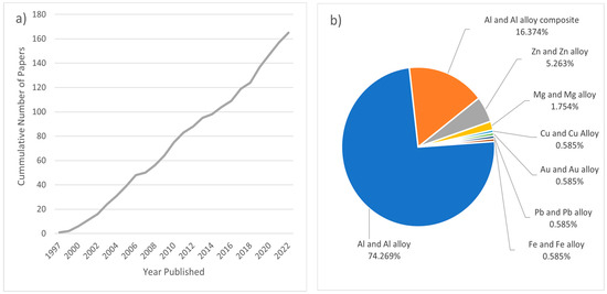
Figure 1.
(a) Cumulative peer-reviewed journal publications that include PCMFP foaming research over the past 25 years; (b) relative percent of publications by material type.
2. Background
2.1. Fundamentals of the Powder Compact Melt Foaming Process (PCMFP)
As mentioned, the PCMFP starts with all constituents in powder form. This includes the metal from which the foam is to be made (sometimes referred to as the matrix), and the gas-releasing blowing agent (typically titanium hydride [45] or calcium carbonate [46]). In PCMFP, the powder constituents are simply mixed, followed by compaction to produce what is known as a bulk foamable precursor, which is subsequently foamed above the melting point of the metal or alloy. The bulk foamable precursor has a stringent requirement of needing to be almost fully dense, with a density typically 99% of theoretical being optimal. It is important to note that, as with powder metallurgy, several basic process parameters will play a role in PCMFP. These include the powder particle size of the metal/alloy, blowing agent, and composite reinforcement (if producing metal matrix composite foams), as well as powder content, powder chemistry, powder strength, and processing environment. The strength of the metal or alloy powder, although not an obvious one at first, has a major impact on the powder compaction stage (foamable precursor production), as discussed later. This leaves some challenges for high-strength powders (e.g., alloy powders), which would otherwise be difficult to press to high densities at room temperature. Figure 2 is a flow chart of the general process with some of its potential sequence variations. Under powder preparation, the primary powder constituents are the metal or alloy composition powder and blowing agent (sometimes referred to as foaming agent) powder. For metallic composites, ceramic reinforcements are also added. The blowing agent powder can be added to the other powders either in an as-received condition, or after it has been heat-treated (or coated). All powders are then either mixed or milled, or a combination of both, and then consolidated to produce the high-density bulk foamable precursor. Some of these consolidation processes can take place either separately or in combination with one another. For example, the mixed powders could be directly spark-plasma-sintered (SPS), or cold-compacted followed by hot extrusion. Finally, the foaming process can take place in a variety of ways, including in an electrically resistive furnace [47], induction heater [48], using laser heating [49], in a furnace equipped with halogen lamps (with infrared reflectors [30]), etc. This is followed by cooling under different conditions. Some work has also investigated post-foaming heat treatments [28,50,51], which can affect the mechanical behavior of the final foam.
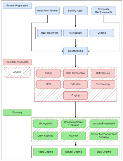
Figure 2.
Examples of PCMFP procedural variations.
2.2. Common Blowing Agents Used in PCMFP
It is noteworthy that blowing agents have been used in the field of powder metallurgy, not only acting primarily when the material is in a semi-molten or molten state (as in PCMFP), but also in the solid state. For example, novel blowing agents such as boric acid were recently used during the ‘sintering’ (not melting) of aluminum and aluminum–alumina composites, resulting in porosity levels of 46–53%, when 50 wt.% boric acid was added [34]. Similar work also considered sintering using the same blowing agent with aluminum–fly ash particulate–aluminum composites [52], or aluminum-cubic boron nitride [53], while CaCO3 was used as a blowing agent for copper foams [35]. It should be noted that the gas release onset temperature of boric acid is considerably lower than those of blowing agents used in the PCMFP, where metal melting rather than solid-state sintering is the goal. Having a blowing agent that releases gas within a molten medium (i.e., a melted powder compact) is naturally geared to provide larger porosity levels and expansions than in the solid state. Typically, the blowing agent releases gas over a range of temperatures. Several blowing agents have been used in PCMFP, with varying gas release temperature ranges. The choice of blowing agents largely depends on the metallic foam to be processed, and its melting point. It is important to make sure that most (ideally all) of the gas is released above the melting point of the metal or alloy to be considered. However, there is generally a mismatch between the gas release temperature of the blowing agent and the melting point of the metal or alloy to be foamed, with the former typically being lower. This can be overcome by increasing the gas release onset temperature of the blowing agent through heat treatment or coating to be compatible with the metal/alloy melting point, or reducing the melting point of the metal through alloying to approach the blowing agents gas release temperature, or both. Table 1 lists examples of different blowing agents used in PCMFP and their reported gas release onset temperatures.

Table 1.
Examples of blowing agents and their reported gas release onset temperatures. Data from [27,39,42,45,54,55,56,57,58,59,60,61,62,63].
The reported gas release onset temperature ranges for a blowing agent such as TiH2 can significantly vary, largely due to inherent factors related to particle size; foaming environment; heating rate; modifications to the blowing agent, either through oxidation or coating; the experimental technique used to measure the gas release temperatures (e.g., due to its superior sensitivity to mass loss compared to gravimetry, thermal desorption spectroscopy (TDS) informs of a lower gas release onset temperature for TiH2, i.e., slightly above 350 °C [64]); or whether the blowing agent is tested while it’s inside the foamable precursor or as a free-standing powder. Hence, the data examples presented in Table 1, should be taken in this light. Soloki and Esmailian [65] also reviewed various carbonate blowing agents used in PCMFP and melt processing.
The particle size of the blowing agent powder is important on two fronts. First, finer blowing agent particles have relatively larger surface areas, which can lead to their agglomeration and poor spatial distribution within the bulk foamable precursor, potentially resulting in non-uniform gas release regions within the microstructure and consequently non-uniform cell structures in the final foam. Second, a decline in TiH2 particle size has been shown to lead to a decline in the gas release onset temperature and rate of gas release [45], which is disadvantageous to the foaming process. For example, fine TiH2 particles (1.8 µm) displayed a gas release (dehydrogenation) onset temperature of 420 °C in comparison to coarser TiH2 particles (~60 µm) that exhibited a 470 °C gas release onset temperature. This point was also investigated by Ibrahim et al. who reported a 50 °C gas release onset temperature decline between 15.27 µm and 4.32 µm TiH2 particles [45,66]. However, the heating rate [67] and the compaction process [56] also influence the blowing agent decomposition behavior. For example, since as-received TiH2 powders typically contain a thin oxide layer, the uniaxial compaction process to produce the foamable precursor can result in the fracture of TiH2 particles (and hence the oxide layers), resulting in the exposure of non-oxidized fresh TiH2 surfaces, which can release gas at lower temperatures. Zeppelin et al. [64] validated this, showing that blowing agent particles within a foamable precursor released gas at a lower temperature than in its loose powder form. They also reported that when hydrides were milled in a hydrogen environment and then analyzed using thermal desorption spectroscopy, they were found to have a similar desorption peak temperature to the compacted and embedded hydrides. Similar findings were also reported by Matijasevic-Lux et al. [42] who found that the hydrogen release temperature in hot-pressed precursors was lower than for loose blowing agent powders. It is obvious that other consolidation processes such as extrusion or rolling can impose even greater shear stresses and strains than in uniaxial compaction, and hence not only result in the fracture of TiH2 particles, but potentially result in a greater TiH2 size reduction (with possible greater implications for foaming).
The environment can also influence the gas release temperatures, as seen in Table 2 for TiH2 (<63 µm). The gas release onset temperature in all three environments (air, He, and vacuum) are about the same; however, there is a difference in the peak gas (hydrogen) release temperatures, which increases from vacuum to helium to air, due to the relative increase in oxygen concentration. Although the He gas used was of very high purity, the unoptimized tubing was believed to have introduced some air, leaving He with an intermediate peak onset temperature [64].
Table 2.
Effect of environment on the onset and maximum gas release temperatures of TiH2 (<63 µm) powder, as shown through thermal desorption spectroscopy. Data from [64].
When TiH2 particles are preheated in air, they develop a thicker oxide coating that delays the release of hydrogen. This is advantageous as it narrows the temperature mismatch between the blowing agent decomposition temperature and the metal/alloy melting point. The foaming potential is however reduced by the preheating process, as shown by Matijasevic and Banhart [22] who found that the available hydrogen dropped nearly 50% in comparison to untreated TiH2. Pretreatment of TiH2 can raise the dehydrogenation temperature onset by 45–170 K, as reported by Kennedy and also by Matijevic et al. [26,42]. The delay in the foaming time causes fewer cracks to be formed in the foamable precursor and the oxide layers aid in pore stabilization [22,42]. The influence of preheating was further investigated by Lehmhus and Rausch [68] wherein the temperature, atmosphere, and heating time were explored. Heat treating TiH2 for 4 h at 500 °C in air caused a larger shift in the decomposition peaks than when heat treating at 400–450 °C for over 10 h, highlighting that the preheat temperature has a greater influence than the duration of the process. Additionally, the initial decomposition peak of TiH2 preheated in Ar varied little between 4 and 16 h, emphasizing the influence of the protective TiO2 layers on hydrogen diffusion and escape. Using synchrotron X-ray and neutron diffraction investigations under flowing and stationery argon and core–shell models [25], it was shown that the dehydrogenation of as-received TiH2 was controlled by an outer hexagonal closed packed hydrogen solid solution while the dehydrogenization of pre-oxidized TiH2 was controlled by a rutile (TiO2) shell. Moreover, every dehydrogenation peak was accompanied by a lattice contraction.
In an interesting study, Muduli et al. [69] examined the effect of customized heat treatments of TiH2 on the foaming of AlSi12.6Mg0.5, AlSi9Mg0.5, and AlSi7Mg0.5. They found that when the peak gas release temperature of TiH2 exceeded the liquidus temperature of the alloy, good foaming resulted; however, when the peak release temperatures were within the semi-molten state of the metal alloy, crack formation was an outcome. Finally, an increase in heating rate has also been found to shift hydrogen desorption peaks to higher temperatures for TiH2 in air [67].
Alternatively, several methods for blowing agent modification have been explored that instead add a coating layer to the blowing agent to delay hydrogen release. The coating methods include ball milling with a ductile metal [70,71,72], combining the blowing agent with a lower-melting-point metal and crushing it into composite particles [73,74], or applying a film layer to the blowing agent particles [75,76,77,78,79,80,81].
2.3. Production of the Bulk Foamable Precursor
A powder-based foamable precursor with a density close to the theoretical density is typically sought for successful foaming. This is important to avoid the loss of released gases from the blowing agent through open porosity networks within the foaming precursor prior to reaching the foaming temperature. It has been reported that 1% porosity may be preferred [82]. It is noteworthy that the relative amounts of open (interconnected) versus closed (isolated) pores in compaction is typically dependent on the relative density of the foamable precursor. It is accepted that above a 92% relative density, closed pores become more dominant [83]; however, open (interconnected) porosity is still present in decreasing amounts until a few percent beyond that point, when they are totally eliminated. Interestingly, Bonaccorsi and Proverbio [84] produced aluminum foams of final densities of 0.78 and 0.75 g/cm3 from foamable precursors that were pressed to 93.5% (lubricated single-action compaction) and 94.1% (lubricated double-action compaction) relative densities, respectively. The authors also pointed to a relevant finding, which is that the density distribution within the foamable precursor can give rise to uneven foaming within the precursor. In uniaxial powder compaction, the friction present between the powders and the inner die walls can give rise to spatial pressure distributions within the precursor, resulting in corresponding internal density distributions. As such, double-action compaction (where the top and bottom punches independently move to compress the powders in a rigid die) leads to more homogenous density distributions than single-action compaction (where only one of the punches moves to compress the powders) [83]. Another reported effect was at the powder compact/die boundaries, in which the least powder densification was observed, leading to poor foaming in these locations [84]. With the data so far, it seems that a logical step is to standardize cold isostatic pressing (CIP) (where the powders are placed and sealed in an elastomeric mold and hydrostatically pressurized with surrounding water medium) as a preferred cold compaction method, which will guarantee uniform density distributions with the foamable precursor, due to the lack of friction between powders and the die. CIP can also result in higher foamable precursor densities at the same applied pressure compared with both single- and double-action compaction, due to the absence of powder/die friction in CIP. A potential drawback, however, could be the relative ineffectiveness of CIP in breaking surface oxides on the metal particle surfaces. However, if the metallic powders were mechanically milled in an inert atmosphere (to first break the oxide layers) prior to CIP, it may yield good results. Interestingly, CIP has been used followed by hot extrusion [24,85], and the latter should be more effective at breaking down oxides. CIP has also been used prior to thixocasting in another study [86]. Other researchers also reported foaming at a foamable precursor relative density of 95% [87]. It is noteworthy that although foaming can be realized at these lower relative densities, it may not be optimum, and a higher density may still produce better foaming. Relative densities as low as ~91% have been shown to result in poor foaming [88], primarily due to the presence of interconnected (open) porosity in the foamable precursor. On the other hand, one study showed precursor densities greater than 99% resulted in a decline in foam expansion, as discussed later.
The metal/alloy particle size and its yield strength can also play a significant role in the PCMFP. Finer particles of the metal or alloy means there are more surfaces, and consequently more surface oxides which could play a role during subsequent foaming (discussed later). In addition, during room temperature compaction, it is more difficult to compact fine metal particles to very high densities, due to an expected higher work hardening rate than coarser particles [83]. This is important, since as mentioned, ideally the bulk foaming precursor needs to be at a density close to theoretical for the best foaming results [89]. The metal/alloy particle strength is also another factor to consider; for example, alloy powders are stronger than their pure metal counterparts, and hence the ability to compact (at room temperature) foamable precursors made of alloy (or otherwise high yield strength) powder to exceedingly high densities could be unlikely. This naturally leads to the consideration of other methods of compaction, typically ones conducted at higher temperatures, such as hot pressing, hot extrusion, hot forging, spark plasma sintering (SPS) and hot rolling, where the alloy yield strength would have been lowered. Consolidation is not the only objective here, but also the breakup of surface oxides on powders that can result in virgin metal to metal contact. In a recent study, foamable precursors produced through extrusion have been shown to exhibit two different expansion regions: one during heating while the precursor is still in the solid/semisolid state, and a larger one upon reaching the liquidus temperature [90]. During the initial expansion stage, microcracks have been observed to form along the extrusion direction, which later open up (inflate) upon further heating in the semisolid state. This results in pore anisotropy, which is reduced (but still remains) after the precursor reaches the liquid state.
In hot pressing, the compaction pressure, temperature, and time can all influence the final foamable precursor density, which in turn influences the foam expansion, as shown in Figure 3 for different hot-pressing temperatures [82,88]. Interestingly, for AlSi8Mg4, a precursor relative density between 97.5 to 99% yields high peak foam expansions which can be in excess of 800% [88]. An interesting and unexpected finding for the AlSi8Mg4 alloy is a decline in expansion at and above a precursor relative density of 99%. This was attributed to the loss of pore nucleation centers as well as to pressure build up (of trapped air) in closed pores to a level that causes cracks, thus allowing the escape of foaming gas.
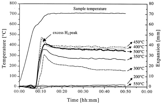
Figure 3.
Effect of hot-pressing temperature on foam expansion [82] (Reproduced with permission from Elsevier).
A range of precursor consolidation temperatures have been reported in the literature depending on the alloy and blowing agent. In the case of TiH2- and ZrH2-based ‘zinc’ precursors, some researchers used hot pressing at 350 °C [64], while aluminum was hot-pressed at 450 °C. Consolidation temperatures of 400–550 °C for aluminum precursors were also reported elsewhere [91]. In this study, the hot pressing of aluminum-TiH2 precursors at 550 °C was found to lead to poor foam expansion, partly owing to excessive aluminum oxidation [91]. In an interesting study, Jimenez et al. [92] compared hot pressing AlSi11 (using heat-treated TiH2) under vacuum to that carried out in air. Not only did the precursors consolidated in air contain more oxygen, but the oxygen level in the vacuum-hot-pressed precursor was similar to that in the powder mixture prior to pressing. In addition, the pore size distribution of the precursors consolidated under vacuum was narrower and 37% percent larger by volume. A higher hot consolidation temperature should facilitate lower yield strengths and improved consolidation and densification of the foamable precursor. The fracture of blowing agent particles and consolidation at temperatures above the gas release temperatures of the blowing agent, may also affect the subsequent foaming process, together with oxygen pickup. It is clear that the foamable precursor consolidation step can significantly affect foaming.
Heat treating the bulk precursor can reveal the effect of temperature on the structure of the bulk precursor (in the absence of external pressure which could otherwise close cracks [93]). Lazaro et al. [94] examined the effect of heat treatment of extruded AlSi10 with 0.8 wt.% TiH2 precursors and reported the development of cracks within the consolidated precursor, and porosity which increased with heat treatment temperature and time. Similarly, Deng et al. [95] also reported the emergence of micro-scale porosity when hot extruded AlSi7Cu4 was heat-treated at 500 °C and 520 °C.
2.4. Mechanisms of Bubble/Pore formation in PCMFP
A central issue with closed-cell metallic foams has been the poor control and spatial size nonuniformity of closed cells, which can have negative implications for mechanical properties. The nonuniformity can stem from the non-uniform coalescence of bubbles into larger ones during foaming while the metal is in the molten state, the non-uniform distribution/agglomeration of TiH2 particles (the main gas source) within the foaming precursor, and the non-uniform density distribution within the foamable precursor. This underscores the fact that an understanding of blowing agent particle dispersion within the foamable precursor, precursor consolidation, bubble nucleation, expansion, film rupture, and coalescence is needed if optimized metallic foams are to be consistently realized. More recently, numerical simulations showed possible benefits of magnetic fields in suppressing drainage during foaming [96]. It is important to point out that the gas source responsible for bubble formation can emanate from a number of sources, including the blowing agent particles and adsorbed species originally on metal powder surfaces from which the foaming precursor was made. The latter has been referred to as an intrinsic source of gas [57].
To gain an understanding of the foaming behavior of metals, some researchers studied the expansion behavior of foamable precursors during the foaming process, using devices such as an expandometer [47,82] or optical expandometer [90]. Such approaches are valuable; however, they do not reveal much regarding internal features developed inside the foam, or dynamic mechanisms. There are two fundamental approaches for studying the pore evolution mechanisms in foaming: ex-situ and in-situ. In ex-situ approaches, typically, the foaming process is interrupted at various stages of foaming, followed by characterization of the solidified foam (using, for example, microscopy), to arrive at some sort of understanding of the mechanisms regarding bubble/pore evolution. Since this approach requires multiple samples interrupted at various times during foaming, it introduces some experimental uncertainty. Figure 4a shows the development of the foam structure, while Figure 4b identifies the stages in the expansion curve produced using an expandometer [82]. Although such approaches are useful, a more insightful approach would be the use of in-situ characterization tools. Since molten aluminum is opaque, it was historically a challenge to gain any sort of understanding of the internal mechanisms during foaming. However, a highly significant breakthrough in understanding real-time foaming events was realized by Banhart and co-workers who initially conducted X-ray radioscopy (the experimental setup is described in detail in [97]) investigations to generate 2D time-resolved images [98] during foaming. Figure 5 shows a schematic of the experimental setup [24]. More recently, they applied X-ray tomoscopy [41], which provides 3D time-resolved images (experimental setup is described in [99]). A significant number of important findings were uncovered through these breakthrough approaches, some of which are discussed below.
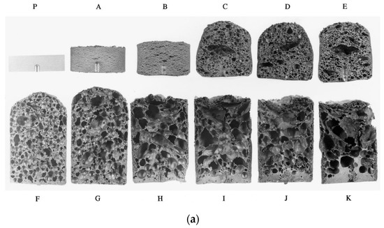
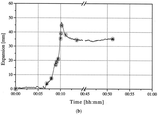
Figure 4.
Pore development (a) and expansion curve (b) shown across the foaming process [82] (Reproduced with permission from Elsevier).
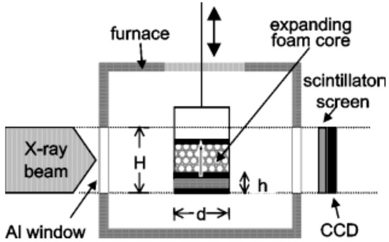
Figure 5.
Schematic of radioscopy experimental setup [24] (Reproduced with permission from John Wiley and Sons).
Depending on the composition of the foamable precursor, the locality of gas-based pore development is not necessarily tied to the location of the blowing agent particles within the microstructure. A series of highly insightful papers have been published targeting the early stage of pore formation in Al alloys, before excessive volume expansions occurred [100,101,102]. The conclusion was that the location of pore evolution depended highly on the alloy composition, and potential weak spots in the microstructure of the foamable precursor. For example, with Al6061, pore initiation started and continued expanding around TiH2 blowing agent particles, whereas for AlSi7, the gas released from the TiH2 particles diffused to the interface between Al and Si particles in the foamable precursor, generating Al/Si debonding, while a local eutectic Al/Si melt allowed for pore initiation and expansion till the pore reached the TiH2 particles, after which pore growth continued directly from the TiH2 particle. Cracking was also reported. For the Al-Si-Cu alloys which have a ternary eutectic with a lower melting temperature than that of the Al/Si alloy, gas emanating from the TiH2 reaches the melt pool and allows for the expansion of pores at these locations. Typically, round pores result. Through recent developments, which led to an increase in the acquisition rate and a reduction in acquisition time, it has become possible to obtain time-resolved 3D images during foaming using X-ray tomoscopy. Specifically, the developments have allowed the unequivocal observation of dynamic events during foaming, such as pore nucleation, pore expansion, and pore coalescence. Unlike X-ray radioscopy, which can produce 2D images of features that may be superimposed on other features along a specific direction, X-ray tomoscopy as a 3D observation tool, allowing for the precise observation of individual features with no overlapping. Using AlSi8Mg4 precursors containing 0.25 wt.% TiH2, Garcia-Moreno et al. [41] divided the foam evolution into four stages: (I) bubble nucleation resulting from the release of adsorbed gas on powder surfaces of the precursor; (II) Bubble nucleation resulting from the decomposition of TiH2; (III) significant bubble expansion and coalescence; and finally, (IV) foam solidification and shrinkage. Since powders are inherently used in PCMFP, the source of gas is not restricted to the blowing agent. In fact, powders with their significant surface area can contain adsorbed moisture or hydroxides on their surfaces, which upon heating can release gases too. An interesting finding in zinc foams is the formation of large amounts (compared to aluminum) of what have been referred to as satellite pores at cell walls, plateau borders, and triple junctions [23]. The abundance of satellite pores in zinc was attributed to the low solubility of hydrogen in zinc and its correspondingly slow diffusion rate (which is not the case for aluminum alloys). These satellite pores are different from the main large pores found in foams typically emanating from gas released from the blowing agent (Figure 6a). The satellite pores have been found to be completely internally covered with oxides, which can also help stabilize the foam. What is interesting is that during the collapse stage of the larger pores, satellite pores continue to grow. In fact, in the absence of any blowing agent, zinc has been found to foam through satellite pores alone.
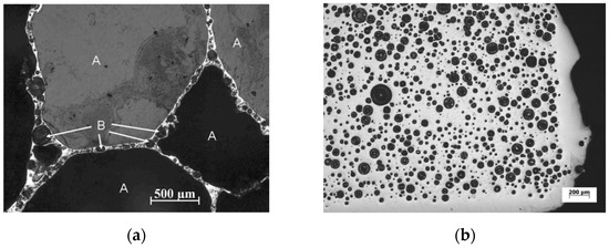
Figure 6.
(a) Cross section of zinc foam, showing main pores and satellite pores where a blowing agent (TiH2) was also used (B refers to satellite pores, and A to the larger pores); (b) a foam structure where no blowing agent was used, showing all satellite pores [23] (Reproduced/adapted with permission from Springer Nature BV).
Figure 6b shows such a microstructure for foaming in the absence of a blowing agent. The stability of foams is a subject of significant importance; Garcia-Moreno et al. [103] recently defined the internal structural stability which is related to time between two film ruptures within a defined foam volume. AlSi8Mg4 was found to be 50% more stable than AlSi9. Moreover, in AlSi8Mg4, the presence of Mg (which oxidizes) leads to more stability. It was also found that within the temperature range 580–640 °C, the bubble coalescence rate was linearly dependent on temperature for both AlSi8Mg4 and AlSi9. It is noteworthy that besides the large pores, microporosity emerging in aluminum and aluminum alloys could result from solidification shrinkage, gas precipitation, gas emanating from the blowing agent, and gas originating from initial adsorbates on powder surfaces [104].
3. Foaming of Metallic Foams and Their Composites
As shown previously in Figure 1b, the foaming of aluminum and its alloys using the PCMFP has been extensively studied; however, other metals and composites have also been investigated. As such, this section reviews research of relevance to all three material categories.
3.1. Foaming of Aluminum Alloys
A number of studies investigated the PCMFP of pure aluminum [84,105]; however, stronger foams and improved foam expansions can be realized through alloying. As for aluminum alloy foams, silicon, copper, tin, zinc, and magnesium have been investigated as alloying elements. A detailed selective sample of alloy foams from experimental literature has been compiled in Table A1. These alloying elements generally serve to lower the solidus temperature, increase the expansion percentage, and reduce the pore size. When excessive alloying particles are added they can form agglomerations which can accelerate the pore coalescence [31]. The melting of the foamable precursor is correlated with expansion, and by lowering the solidus temperature, this process begins closer to the blowing agent decomposition temperature. The addition of Mg has been shown to increase the expansion rate and reduce thinning of the cell walls during foaming [106]. The addition of 0.6–1 wt% Mg results in the formation of MgAl2O4 phases that are wettable with Al and increase the viscosity of the melt [107]. The addition of copper (2–6 wt.%) increases the viscosity of the melt and shortens the expansion period. Additionally, unfoamed layers along the sides and top of the product are reduced [108]. Foams with a higher Cu content also exhibit smaller pore sizes at the same expansion rate. A systematic study was conducted by Helwig et al. [109] by adding Mg and Cu at varied contents to Al-Si alloys. While Cu addition produces finer pores than foams without Cu, the result is even greater with Mg additions. One the other hand, the addition of Sn affects the blowing agent decomposition process by reducing the local pressure around the TiH2 particles and by encapsulating the particles as the Sn melts [110] (due to the insolubility of Sn in solid Al). The increased cell wall stability led to a 30% increase in the number of pores for 1–3 wt.% Sn contents. Additionally, the pore sphericity was improved by Sn additions, and stability was achieved due to the influence of Sn in reducing the surface tension of molten aluminum. All the above findings serve as great insights into the importance of alloying additions.
As mentioned, in addition to pure aluminum [84,105], a large number of Al alloys have been investigated in PCMFP, including AlSi6 [109], AlSi7 [64], AlSi9 [43], AlSi10 [90], AlSi12 [111], AlSi9.6Mg1 [112], Al6061 (0.4–0.8 Si, 0.8–1.2 Mg, and <0.7 Fe) [82], AlSi11Cu4Zn2 [113] (a quaternary alloy). The ternary alloy AlSi8Mg4 was found to result in good expansion and fine/uniform pore sizes and structures, as seen in Figure 7 [109]. This successful AlSi8Mg4 alloy was not only patented but has also found commercial application [43,114]. Further investigations into the AlSi8Mg4 alloy revealed that an island of compositions around this alloy exists, where good foaming is still possible [114]. It was found that increasing the Si and decreasing Mg results in better expansion. Moreover, a correlation was found between a certain liquid fraction range (40–60%) just above the solidus temperature and increased expansion. As an outcome of this comprehensive study, AlSiMg3 was found to have the highest expansion with an acceptable structure of the foam, while AlSi9Mg5 provided the best structure of the pores and an expansion that is acceptable. It was concluded that AlSi8Mg4 provided a good compromise between the two compositions.
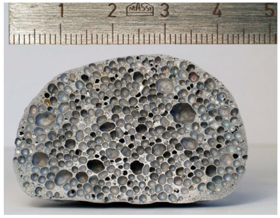
Figure 7.
AlSi8Mg4 alloy displaying good foam structure [109] (Reproduced with permission from Springer Nature BV).
The oxidation of the Al/Al alloy powder has been found to play an important role in the foaming process. Asavavisithchai and Kennedy [91] reported that oxidation of aluminum powder to a level enough to raise the oxygen content to 0.3–0.4 wt.% was beneficial for foam expansion and foam stability; however, oxygen contents at or above 0.54 wt.% resulted in increased viscosity to levels that interfered with the foaming process. The stability of cell structures has been reported to be favored by the presence of oxides, which tend to migrate during foaming to the cell/vapor interface to provide stability [115]. The presence of oxide particle cluster networks which are broken during pore nucleation and fragmented into isolated fragments (still having particle character), was put forward by Körner et al. [116] to result in a strong stabilizing disjoining pressure. However, foaming in air may provide more opportunity for excessive oxide formation, which can hinder foaming [117], if not optimized.
Prosviryakov et al. [118] conducted an interesting study on the oxidative milling of Al-12Si alloy powder. It is well known that aluminum powder contains a nanometric alumina (Al2O3) layer on the surface. During ball milling, this oxide layer is broken, exposing virgin aluminum surfaces to further oxidation. In this process, the milling was conducted in air, and every 2 min, the vial was opened to introduce air. The approach resulted in a gradual increase in aluminum oxide (Al2O3) to levels of ~1.7 wt.% content after 15 min of milling and 2.1 wt% after 20 min of milling. The increase in milling time had an effect of improving foaming and reducing cell size. However, milling at 20 min resulted in inferior foam characteristics, attributed to the excessive cold welding observed after this length of time, which resulted in larger Al-12Si powder size and poor TiH2 distribution within the foaming precursor. Excessive amounts of oxides can also resist pore expansion, resulting in poor foaming, such as the case when excessive amounts of Mg is added to Al-Si alloys [109]. The positive effects of oxides have also been observed for other metals. For example, in zinc foams, where Chethan et al. [23] varied the oxide content in zinc powder by oxidation and reduction during annealing in appropriate atmospheres and observed an increase in maximum expansion and expansion rate with an increase in oxide content from 0.026 wt.% to 0.061 wt.%.
3.1.1. Foaming Environment
The foaming environment directly affects the volume expansion of individual pores. Foaming has been conducted under gas pressures between 10 mbar and 40 bar [93,119] and under inert atmospheres [87,93]. Foaming in air can cause oxidation, particularly at higher pressures, leading to argon [93,119] and nitrogen [87,93] being used as shielding gases.
Low-pressure foaming leads to less spherical pore shapes and increased gas loss through cracks in the matrix. While high-pressure foaming, in contrast, produces spherical small pores and reduces coalescence with a smaller maximum expansion [93,119]. Having a relatively high blowing agent content, 2.5 wt%, when foaming at 40 bar, was found to produce well-distributed small pores and good expansion (this is in contrast to foaming under atmospheric pressure which results in coarser pores [120,121]). However, increasing the blowing agent content does also significantly increase the cost of production [21].
Limiting the volume expansion using mechanical pressure has been investigated by Garcia-Moreno et al., in which the expansion of the foam is mechanically impeded until the matrix has melted and the blowing agent decomposition has started [122]. After releasing the piston, the foam quickly expands to the available volume.
The foaming environment impacts the pore shape, size, distribution, and drainage (i.e., the migration of molten metal to the bottom of the foam). Microgravity foaming by Garcia-Moreno et al. demonstrated a homogenous liquid distribution that significantly reduced drainage [98].
3.1.2. Effect of Heating and Cooling Rates
Due to the blowing agent decomposition temperature often being below the liquidus temperature of the metal, insufficient heating rates during foaming, <1 K/s, can lead to increased gas loss and the formation of cracks in the foamable precursor, resulting in lower expansions [123]. In contrast, raising the heating rate, >3 K/s, can increase the maximum expansion but concomitantly causes a collapse of up to 35% during cooling, as shown in Figure 8. Notable expansion with minimal collapse occurs in the 1–5 K/s range, though optimization by alloying is essential [123]. Lower heating rates, 0.12–0.5 K/s, were also explored by Kobashi et al. [124] but little difference was observed in that range. It is important to point out that at higher heating rates, process control could also be lost as the outer surface of the precursor could be heated faster than the interior, resulting in inhomogeneous foaming. As such, Youn and Kang [48] resorted to induction heating as an alternative heating method for more uniform heating during foaming. Not only can the heating rate affect foaming but so does the cooling rate at the end of the foaming process. Following foaming, foams can be quenched with air or water to freeze the pore structure or allowed to cool in ambient air [31,73,125]. Freezing the pore structure in place through quenching enables the analysis of pore growth/evolution and can reduce coalescence [37]. Additionally, increasing the cooling rate (above 2.5 K s−1) can also mitigate the gravity-driven drainage that is most noticeable on the bottom layer of the foam [126,127]. However, Mukherjee et al. [126] showed that too high of a cooling rate can introduce thermal shock to the foam, causing cell rupture which reduces the mechanical properties. Additionally, having too low of a cooling rate has also been shown to lead to an increased number of cell ruptures and defect formation, caused by the continuing decomposition of the blowing agent during solidification, in what is referred to as solidification expansion [30].
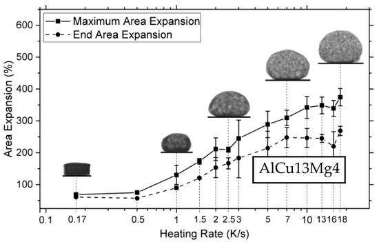
Figure 8.
The deviation of end expansion from peak expansion with increased heating rates [123] (Reproduced with permission from MDPI).
3.2. The Foaming of Non-Aluminum Metals and Alloys
Although aluminum foams have received the vast majority of attention, other metals and alloys have also been investigated. For example, lead alloys [39], zinc alloys [64], gold alloys [44], copper [128], cast iron [32], and magnesium [129] as shown in Table A1.
Several studies have been directed at foaming zinc using PCMFP. As a foam, zinc has a number of advantages, including a low melting point (419.5 °C) which opens the door to a wider range of blowing agent selection. Chethan et al. [23] conducted a fundamental study to investigate the effect of oxide content on zinc foaming. Oxides were found to stabilize zinc foams, and expansion was improved with an increase in oxygen content (as mentioned previously). The emergence of satellite pores was also a feature of zinc foams, to a level that was more pronounced than in aluminum alloys. Zeppelin et al. [64] investigated the foaming of zinc using three different blowing agents, MgH2, ZrH2, and TiH2, employing thermal desorption spectroscopy to determine the gas release onset temperatures of the blowing agents, as a more sensitive method compared with gravimetry.
Koichi and Takiguchi [28] investigated the foaming of a Zn-22Al eutectoid alloy with TiH2. Both the effect of holding time and temperature were investigated; in both, the pore content increased followed by a decline with a maximum pore content of 66% being realized. Dendrites (shown in Figure 9) were observed in the cell wall microstructure which were later removed via post-foaming solution treatment followed by quenching. The final foams displayed improved mechanical behavior primarily due to the refined microstructures and an enhanced strain rate sensitivity of the yield strength. Moreover, both the yield strength and absorbed energy were shown to be superior to Alporas aluminum foams. Using CaCO3 as the blowing agent, Yang et al. [130] added magnesium to zinc and pursued a foamable precursor sintering step prior to hot pressing for the purpose of strategically forming low-melting-point intermetallic phases. The exact compositions of the intermetallic phases after sintering depended on the initial composition of the Zn/Mg mixture. For example, for Zn9Mg1, the intermetallics Mg2Zn11 and MgZn2 were formed, whereas Mg7Zn3 and Mg2Zn3 formed in the Zn7Mg3 composition. Although the Zn9Mg1 composition displayed good strength, the plateau region of the stress–strain curve displayed jagged features, owing to the brittle nature of the intermetallics that remained post foaming.
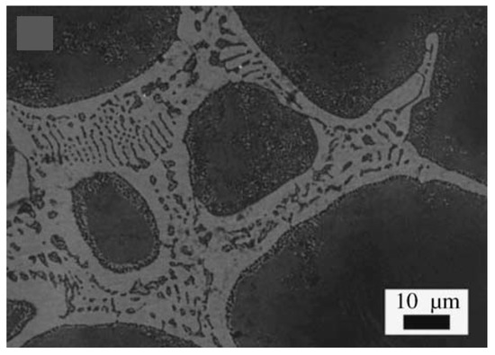
Figure 9.
The presence of dendrites in cell wall microstructure of Zn-22Al [28] (adapted with permission from Elsevier).
In relation to lead and lead alloys, Irretier and Banhart [39] conducted an extensive study covering the influence of lead powder characteristics (including particle size and oxygen content), blowing agent, and alloying elements on foaming. A number of important findings were reported, placing some emphasis on the lead powder characteristics, and the precursor consolidation process. For example, hot pressing was not a viable method for producing the foamable precursor, largely due to its inability to break the PbO layer on the lead particle surface, and in turn generate metal–metal contact. Hence, extrusion was the preferred approach for consolidation; however, it too was still not viable for lead powder with excessive oxide content, again due to the inability to break the surface oxides. With low levels of oxides not being appropriate for foaming, an intermediate level of oxides (3 vol.% PbO) and a particle size of 82 µm represented the best powder used. The blowing agent used was basic lead (II) carbonate (PbCO3)2∙Pb(OH)2 which releases carbon dioxide and water (interestingly water-free lead carbonate, PbCO3, did not result in good foaming). The addition of tin (even as part of a ternary alloy Pb-Sn-Sb) was found to be very beneficial in producing better foams than pure lead, whereas the addition of antimony made the foam more susceptible to drainage and cell collapse. The study, however, resulted in the productions of foams with a density of 1 g/cm3 (note that the density of lead is 11.34 g/cm3).
There has also been an attempt to foam precious metals such as gold using PCMFP, for possible jewelry or design applications [44]. The foaming of gold initially posed a problem on two fronts. First, its relatively high melting point (1064 °C) compared to aluminum (660 °C) meant that the use of conventional blowing agents such as TiH2 would be unproductive as the decomposition temperature of TiH2 is significantly below the melting point of gold. The second is the absence of oxides in gold (a noble metal), which would normally act as closed-cell stabilizers during foaming. As such, Banhart [44] considered alloying elements (for example, silicon and germanium) that would allow a reduction in the melting point of gold, and allow a more effective use of blowing agents such as TiH2 and ZrH2. Although a six-time volume expansion was reported (~84% porosity), the cells appeared rough and irregular, and the color deviated from the pristine gold color initially intended, partly due to the amount of alloying elements present that resulted in a color shift. The ZrH2 and TiH2 blowing agents performed in a similar fashion, whereas MgH2 was not effective. The research is, however, a good first attempt, with further research needed, possibly through the optimization of other conventional PCMFP parameters, as reported. In another study, cast iron (Fe-2.5C) [32], with a liquidus temperature of ~1350 °C, was foamed using either strontium carbonate (gas release temperature of ~1290 °C) and magnesium carbonate to yield foams with relative pore contents between 0.36 and 0.62, with coarse pores sizes; more research is needed to that end to improve homogeneity. Possibly, the unoptimized precursor densities may have played a role in the limited porosity observed.
Magnesium already has an advantage over aluminum in terms of a lower density (1.74 g/cm3) compared with 2.7 g/cm3 for Al. Its melting point is also slightly lower (650 °C vs. 660 °C); however, it is highly pyrophoric, which means it needs to be foamed in a protective atmosphere, for example, 99% CO2/1% SF6 [131]. A number of studies have been reported on the foaming of Mg via PCMFP [46,129,131]. These studies used CaCO3 as a blowing agent, with a gas (CO2) release onset temperature of ~600 °C, as determined through thermal gravimetry measurements. The foaming of Mg with CaCO3 did not yield good results, owing to loss of gas due to the early decomposition of CaCO3, which leads to precursor cracking and gas escape, and potentially the reaction of the CO2 released and the Mg to form magnesium oxide, and hence the addition of aluminum to Mg was needed to produce good foaming [131]. This was accomplished by adding a sintering step prior to hot pressing to intentionally grow low-melting-point intermetallics (e.g., Al12Mg17 and Al3Mg2) such that their melting would trigger a reaction with CaCO3 to release carbon monoxide, which in turn successfully generates good Mg alloy foams. The idea was later extended to other alloying elements such as Cu and Zn [129], which likewise generated other intermetallics that promoted better foaming. The persistence of intermetallics within the microstructure after foaming, however, can result in a deterioration in the compressive properties of the processed foams. As such, a more elaborate investigation including ternary alloying additions of Mg-Al-Zn and intermetallic phase content was conducted and a second criteria (in addition to the melting of intermetallics) was introduced for good foaming. The criteria is that the amount of liquid formed following melting should be greater than 30 wt.% within 5 °C, and the range over which the intermetallic melts should be less than 110 °C [46]. The Mg80Al19Zn alloy was found to produce the best compressive strength. Cu-Mg alloy foams [59] were formed, again taking advantage of the solid-state reaction between Cu and Mg to form low-melting-point intermetallics through a sintering step. This time, the intermetallics formed were Mg2Cu and MgCu2, which ended up making the foam brittle, but the presence of magnesium can increase the compressive strength. It would be interesting to avoid the sintering process all together and grow the intermetallics during the hot-pressing step by raising the temperature; it may even accelerate the formation of these intermetallics in shorter times.
3.3. PCMFP of Aluminum-Composite Foams
Control of the cell size, homogeneity, and morphology can positively influence the mechanical behavior of metallic foams. However, another factor is the cell wall strength, which can be improved either through alloying and/or the addition of composite reinforcements. Selected PCMFP composite foams found in experimental literature is given in Table A2. Such additions of ceramic reinforcements can also influence the foaming process. For example, Kennedy and Asavavisithchai [132] investigated the effect of three ceramic reinforcements (silicon carbide, alumina, and titanium boride) on the foaming of aluminum. All reinforcements were added at 3 vol.% and resulted in an increase in expansion compared with pure aluminum, from 350% to 450%, owing to a reduction in the minimum critical cell wall thickness prior to rupture. Moreover, the wetting behavior of the reinforcements (and alumina initially present on the aluminum powder surfaces) with molten aluminum played a role in the stability of the foams. Improved wetting, signified by a lower contact angle at the melt–particle interface, enabled SiC addition to reduce the rate of drainage and produce stable composite foams in the foaming times investigated. Note that the SiC particles resided within the cell walls (similar observations were also noted for SiC particles in AlSi7 foams [133]). In another study, using thixocast precursors, the addition of either alumina or SiC up to 5 wt.% content, resulted in lower drainage and less cell collapse, with the efficiency increasing with the increase in particle content or a reduction in reinforcement particle size [86]. Interestingly, spinel particles produced through a reaction between alumina on aluminum particle surfaces and added magnesium also shows very good wetting and results in similar behavior, providing stability and reduced drainage [106]. Hailat [134] investigated the foaming behavior (at 750 °C) of aluminum 6061-SiC composites to higher SiC contents (SiC 4–10 wt.% loading), and observed a decline in expansion with an increase in SiC content. In another study [133], however, the addition of SiC to AlSi7 (with a TiH2 blowing agent) resulted in an increase in expansion at 3 vol.% SiC, followed by a similar decline at a higher SiC content up to 10 vol.%. However, the expansion levels were significantly larger than the ones observed by Hailat, probably due to the difference in the alloy compositions. The foaming was conducted at the same temperature (750 °C), but the same trend was likewise observed at 780 °C and 810 °C. Moreover, the particle size of SiC was also found to affect foaming with the best expansion occurring at a 3 µm particle size at 810 °C. More positive results on expansion were, however, reported at 10 wt.% SiC content elsewhere [135] (where the precursor had been forged), which resulted in increased expansion as compared with SiC-free aluminum foams. On the other hand, the addition of only 1 vol.% of nano-SiC particles (40 nm) to aluminum and using CaCO3 as a blowing agent, resulted in a decline in the closed cell size by ~50% compared with unreinforced aluminum, and reduced drainage, resulting in pore homogeneity [136]. Here, the extremely small size of the SiC particles should provide a significantly larger number of SiC particles at this small volume content, which should contribute to their effectiveness. The addition of other reinforcements at higher volume fractions was investigated by Mahmutyazicioglu et al. [137], where it was found that an addition of alumina reinforcements to aluminum 6061 resulted initially in a reduction in drainage up to 5 vol.% alumina; however, again, at a 10 vol.% alumina addition, increased drainage was observed resulting in an inhomogeneous cell size distribution. It seems that more research needs to be directed at improving foaming at higher ceramic reinforcement contents.
In another study, the addition of 3 vol.% graphite in the foaming of AlSi12Mg0.6Fe0.3 was found to perform worse than SiC at the same volume content; this was again attributed to the comparatively poorer wetting of graphite [138]. In an interesting study, Klinter et al. [139] foamed four different matrix materials (pure aluminum, AlMg1, AlCu7, AlSi11.5) reinforced with 3 vol.% alumina particles. The idea was to observe the effects of wetting by the different matrix materials. It was found that AlMg1/alumina generated the best expansion, foam stability, and pore morphology, followed by AlCu7/alumina, Al/alumina, and AlSi11.5/alumina. Moreover, the alumina particles were found to be located within the cell walls of AlMg1 and AlCu7 matrices, which again points to the improved wetting.
In another study, the addition of nanoscale alumina up to 15 wt.% did not result in any significant expansions [140]. Furthermore, an increase in density was reported, as well as agglomeration at the higher reinforcement contents. We believe that the use of 150 nm particle size aluminum may have also negatively impacted foaming due to the expected significant oxides present on these particles which have exceedingly large surface areas. Due to the superior properties of carbon nanotubes, a number of studies incorporated them in both open-cell [20,21] and closed-cell [111,141,142,143] metallic foams. Duarte et al. [143] investigated a colloidal step to aid in the dispersion of functionalized 2–5 nm diameter and 10–30 µm length multiwall carbon nanotubes (MWCNTs-COOH) in AlSi12. The added MWCNTs were dispersed in the cell walls, resulting in increased hardness from ~50 HV for unreinforced cell walls to ~93 HV for those reinforced with MWCNTs. Another way to improve bonding between MWCNTs and aluminum is through MWCNT coating; as such, Ni-coated MWCNT was recently added to AlSi8Mg4 [141]. However, both density and pore size were increased by the addition of the MWCNTs. In a separate study, a hybrid composite foam was recently investigated where MWCNT and SiC were added together in different proportions to AlSi12; CNT agglomeration was again reported, with inconclusive results as to the effects of SiC and MWCNTs on the expansion behavior of the foams [76]. However, more positive results were reported for a graphene-nanosheet (decorated with Cu nanoparticles, i.e., GNS@Cu)-reinforced Al/Si foams, where the nanosheets provided an increased pore nucleation density, and refined and more homogenous pores compared with A-Si foams [144]. Figure 10 shows the pore refinement with the increased addition of GNS@Cu up to 0.8 wt.%.
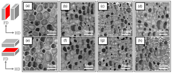
Figure 10.
Micrographs of (a,e) Al-Si foams, (b,f) 0.2 wt% GNSs@Cu reinforced Al-Si nanocomposite foams, (c,g) the 0.4 wt% GNSs@Cu reinforced Al-Si nanocomposite foams and (d,h) the 0.8 wt% GNSs@Cu reinforced Al-Si nanocomposite foams [144] (Reproduced with permission from Elsevier).
4. Alternative Approaches
In this section, a brief reference to some of the promising foaming approaches is provided.
The process of mechanical milling is extremely versatile, in producing powders of varying designs and internal structures. Once used to produce oxide dispersion strengthened alloys [145], the process has recently been used [70,146] to disperse TiH2 particles inside aluminum powders, to produce Al-TiH2 composite particles. These particles can now be considered as foamable precursors in “particle” form as opposed to the conventional bulk form. The approach may have advantages in cladding applications, the ability to selectively foam parts of a component, additive manufacturing, the production of micro-scale foams, or even allowing foaming to take place at lower relative densities of bulk foamable precursors, since the TiH2 is already encapsulated in the aluminum particles. Figure 11a,b shows a macro-scale foamable precursor “particle” and its cross-section, showing the dispersed TiH2 particles. The size of TiH2 particles is smaller than the as-received particle size, due to fracture processes during the mechanical milling process, leading to TiH2 particle size reduction. The process was also applied using a process control agent during mechanical milling to produce micro-scale foamable precursor particles [146]. Figure 12a,b, shows two particles before and after unrestricted foaming in air; as can be seen, the uneven foaming shape is due to breaks in the oxide surface layer allowing outwards expansion (protrusions) to take place preferably there, leading to irregular foamed particles.
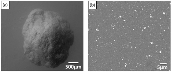
Figure 11.
(a) Foamable precursor in particle form. (b) Cross-section of particle showing dispersed TiH2 blowing agent particles (white) [70] (Reproduced with permission from Elsevier).
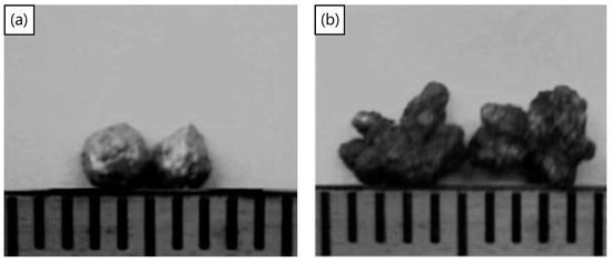
Figure 12.
(a) Two foamable precursors before foaming and (b) after foaming [70] (Reproduced with permission from Elsevier).
The foaming of foamable bulk precursors using the laser heating process was discussed by Kathuria [49,147]. The laser can be applied directly to a precursor with a photoabsorbent coating, allowing tailorable sections of varying porosity. Laser-assisted foaming allows for faster heating and cooling rates due to localized laser heating. The heating can be varied by changing the processing speed and the laser intensity. By varying the laser dwell time between 0.16 and 0.86 s, Kathuria [147] was able to produce foams with cell sizes from 0.2 mm to 3 mm. Additionally, once the laser is shut off, the faster cooling is advantageous to control the degree of foaming and aid in pore stabilization [147].
Laser heating has also been applied as an indirect heating source, through a tube [148] or crucible [40,41,43,114], enabling precise control over the heating profile and integration into existing equipment that might not accommodate a traditional furnace setup. Using this method, Campana et al. [148] was able to connect two previously foamed sections by foaming a precursor between them using localized laser heating. Interestingly, the laser-assisted heating process enables foams that are produced separately to be seamlessly integrated as a continuous foam, without heating large sections, using adhesives [149], or a confluence of alloys [150]. This may be particularly interesting in large assemblies or repairs where individual foam components need to be added or replaced.
A novel layered foaming method was developed by Hangai et al. [151], wherein a powder foamable precursor of a lower melting alloy was compacted on a placeholder compact of pure aluminum and NaCl. The layered powders were spark-plasma-sintered to consolidate the compact and then the PCMFP side was exposed to heat lamps for foaming. Following foaming, the NaCl particles were washed out, to reveal the open cell network. Using this method, a layered open- and closed-cell foam was produced.
5. Conclusions
Since its inception decades ago, the powder compact melt foaming process has been investigated for the foaming of numerous metals and alloys, and to a lesser extent, composites. The most investigated materials are aluminum and its alloys, with fundamental investigations carried out revealing the effects of the blowing agent (and its modifications); alloy composition; metal/alloy powder surface oxide; compaction method; and foaming temperature, time, heating/cooling rates, and environment, on the foaming process. Some of the notable and very recent important insights were brought about by time-resolved radioscopy and tomoscopy investigations which shed light on fundamental mechanisms during foaming, including bubble nucleation, coalescence, collapse, and cell wall defect generation. One of the most promising ceramic reinforcements is silicon carbide due to its wetting properties with aluminum. Graphene nanosheets may also hold promise as reinforcements. Interesting approaches include laser-assisted foaming and foamable “particles” precursors which can open new application directions in the field. Areas that may still warrant further fundamental research include processing and properties of non-aluminum metal/alloys foams, metal-composite foams especially at high reinforcement volume fractions, functionally graded materials via PCMFP (which should be inherently very amenable to such material designs) and investigating new high-temperature blowing agents to expand the process to higher-melting-point alloys.
Author Contributions
Conceptualization, N.B. and K.M.; methodology, N.B. and K.M.; software, N.B.; validation N.B. and K.M.; formal analysis, N.B.; investigation, N.B. and K.M.; resources, N.B. and K.M.; data curation, N.B.; writing—original draft preparation, N.B. and K.M.; writing—review and editing, N.B. and K.M.; visualization, N.B.; supervision, K.M.; project administration, K.M.; funding acquisition, N/A. All authors have read and agreed to the published version of the manuscript.
Funding
This research received no external funding.
Data Availability Statement
Not applicable.
Acknowledgments
The authors would like to thank Monali Patil for her initial assistance with the literature search for metallic foam composites.
Conflicts of Interest
The authors declare no conflict of interest.
Appendix A
Table A1.
Production and Expansion Data of Selected PCMFP Metallic Foams.
Table A1.
Production and Expansion Data of Selected PCMFP Metallic Foams.
| Matrix | Blowing Agent | Wt.% | Comments | Precursor Relative Density | Bulk Density (g/cm3) | Expansion (%) | Reference |
|---|---|---|---|---|---|---|---|
| Al | CaCO3 | 10 | - | - | - | 14.8 | [105] |
| Al | CaCO3 | 15 | - | - | - | 52.0 | [105] |
| Al | CaCO3 | 20 | - | - | - | 53.0 | [105] |
| Al | TiH2 | 0.6 | - | - | - | 233.3 b | [152] |
| Al | TiH2 | 0.6 | - | >99% | - | 400 | [91] |
| Al | TiH2 | 0.6 | - | - | - | 350 | [115] |
| Al | TiH2 a | 0.6 | - | >99.4% | - | 162–254 | [26] |
| Al | TiH2 a | 0.6 | - | >99% | - | 350 | [91] |
| Al | TiH2 | 0.6 | Coarse Al, 0.536 wt% Oxygen | - | - | 440 | [153] |
| Al | TiH2 | 0.6 | Coarse Al, 0.061 wt% Oxygen | - | - | 170 | [153] |
| Al | TiH2 | 0.6 | Matrix preheated in air | >99% | - | 420 | [91] |
| Al | TiH2 | 1 | - | 95–96% | - | 164 | [110] |
| Al | TiH2 | 1 | - | >99.4% | 0.59–0.79 | - | [76] |
| Al | TiH2 | 1 | - | 98.6% | 0.59 | 300 | [45] |
| Al | TiH2 a | 1 | Ni-coated TiH2, 16.4 wt% of TiH2 | >99.4% | 0.60–0.76 | - | [76] |
| ADC12 | TiH2 | 1 | - | - | - | 400.00 b | [150] |
| Al 5083 | TiH2 | 1 | - | >99% | - | 88.68 b | [154] |
| Al 6061 | TiH2 | 0.6 | - | - | - | 320 c | [82] |
| Al 6061 | TiH2 | 0.8 | - | - | 0.59 | - | [155] |
| Al 6061 | TiH2 a | 0.8 | - | - | 0.62 | - | [155] |
| Al 6082 | TiH2 | 0.6 | - | - | 0.58 | - | [155] |
| Al 7020 | TiH2 | 0.6 | - | - | 0.58 | - | [155] |
| Al 7075 | TiH2 | 0.6 | - | - | 0.60 | - | [155] |
| AlMg0.6 | TiH2 | 0.6 | - | - | - | 472 | [107] |
| AlMg15Cu10 | AlMg50 (via adsorbed gases) | - | - | - | - | 248 | [57] |
| AlMg26Cu10 | AlMg50 (via adsorbed gases) | - | - | - | - | 311 | [57] |
| AlMg4.5Mn | CaMg (CO3)2 | 3 | Thixocasting | - | - | <100 | [156] |
| AlMg4Si6 | TiH2 a | 1 | - | - | - | 335–505 | [109] |
| AlMg4Si6Cu4 | TiH2 a | 1 | - | - | - | 275–380 | [109] |
| AlMg4Si8 | TiH2 a | 1 | - | - | - | 450–555 | [109] |
| AlMg6Si6 | TiH2 a | 1 | - | - | - | 285–365 | [109] |
| AlSi10.2 | TiH2 | 1.5 | N2 atmosphere | 95% | 0.505 | - | [87] |
| AlSi10Cu9Zn3 | TiH2 | 0.5 | - | 2.92 d | - | 475 | [113] |
| AlSi10Mg | TiH2 | 0.4 | 1000 mbar Ar atmosphere | - | 0.31–0.65 | - | [119] |
| AlSi10Mg | TiH2 | 0.4 | 2300 mbar Ar atmosphere | - | 0.48–0.75 | - | [119] |
| AlSi10Mg | TiH2 | 0.4 | 2800 mbar Ar atmosphere | - | 0.49–0.74 | - | [119] |
| AlSi11Cu4Zn2 | TiH2 | 0.5 | - | 2.79 d | - | 440 | [113] |
| AlSi12 | TiH2 | 1 | Matrix ball milled in air | 2.61–2.64 d | 0.93 | - | [118] |
| AlSi12.6Mg0.5 | TiH2 a | 0.5 | - | >98% | - | 244 | [69] |
| AlSi12Mg0.6Fe0.3 | TiH2 | 0.4 | - | >99.75% | 0.52 | - | [138] |
| AlSi4 | TiH2 a | NG | - | - | - | 420.8 b | [31] |
| AlSi6 | TiH2 a | 1 | - | - | - | 450–600 | [109] |
| AlSi6Cu2 | TiH2 a | 1 | - | - | - | 400–480 | [109] |
| AlSi6Cu4 | TiH2 a | 0.5 | - | - | - | 280 | [30] |
| AlSi6Cu4 | TiH2 a | 0.5 | - | >99% | - | 450 c | [22] |
| AlSi6Cu4 | TiH2 | 0.5 | 1 bar Ar atmosphere | - | - | 330 c | [93] |
| AlSi6Cu4 | TiH2 a | 1 | - | - | - | 430–510 | [109] |
| AlSi6Cu4 | TiH2 | 2.5 | 5 bar Ar atmosphere | - | - | 450 c | [93] |
| AlSi6Cu4 | TiH2 | 2.5 | 10 bar Ar atmosphere | - | - | 315 c | [93] |
| AlSi6Cu4 | TiH2 | 2.5 | 20 bar Ar atmosphere | - | - | 310 c | [93] |
| AlSi6Cu4 | TiH2 | 2.5 | 40 bar Ar atmosphere | - | - | 175 c | [93] |
| AlSi6Cu4 | ZrH2 | 0.5 | Precursor Preheat | >99% | - | 150 b | [27] |
| AlSi6Cu6 | TiH2 a | 1 | - | - | - | 400–450 | [109] |
| AlSi7 | TiH2 | 0.5 | - | - | 0.41–0.88 | - | [157] |
| AlSi7 | TiH2 | 0.5 | - | - | - | 436 | [68] |
| AlSi7 | TiH2 a | 0.5 | - | - | - | 371 | [68] |
| AlSi7 | TiH2 a | 0.5 | - | - | - | 420 | [30] |
| AlSi7 | TiH2 | 0.6 | - | - | - | 510 c | [82] |
| AlSi7Cu4 | TiH2 | 0.5 | Precursor Preheat | - | - | 128 | [95] |
| AlSi7Mg0.5 | TiH2 a | 0.5 | - | >98% | - | 316 | [69] |
| AlSi8Cu13Zn5 | TiH2 | 0.5 | - | 3.07 d | - | 420 | [113] |
| AlSi8Mg4 | KBH4 | 0.5 | - | - | - | 375 c | [56] |
| AlSi8Mg4 | LiAlH4 | 0.5 | - | - | - | 290 c | [56] |
| AlSi8Mg4 | LiBH4 | 0.5 | - | - | - | 320 c | [56] |
| AlSi8Mg4 | NaBH4 | 0.5 | - | - | - | 330 c | [56] |
| AlSi8Mg4 | TiH2 | 0.5 | - | - | - | 325 c | [56] |
| AlSi8Mg4 | TiH2 a | 1 | - | 97.20% | - | 888 | [88] |
| AlSi9 | TiH2 | 0.5 | - | 99.83% | - | 450 | [108] |
| AlSi9.6Mg1 | TiH2 | 0.8 | - | 98.90% | - | 240 c | [112] |
| AlSi9Cu2 | TiH2 | 0.5 | - | 99.96% | - | 544 | [108] |
| AlSi9Cu3 | CaCO3 | 3 | Thixocasting | - | - | 150 | [156] |
| AlSi9Cu3 | CaCO3 | 5 | Thixocasting | - | - | 200 | [156] |
| AlSi9Cu3 | CaMg(CO3)2 | 3 | Thixocasting | - | - | 266 | [156] |
| AlSi9Cu3 | CaMg(CO3)2 | 5 | Thixocasting | - | - | 282 | [156] |
| AlSi9Cu3 | TiH2 | 0.5 | - | - | - | 492 | [113] |
| AlSi9Cu3 | TiH2 a | 0.5 | - | - | - | 447 | [113] |
| AlSi9Cu4 | TiH2 | 0.5 | - | 99.90% | - | 585 | [108] |
| AlSi9Cu6 | TiH2 | 0.5 | - | 99.96% | - | 647 | [108] |
| AlSi9Mg0.5 | TiH2 a | 0.5 | - | >98% | - | 324 | [69] |
| AlSn1 | TiH2 | 1 | - | 98–99% | - | 484 | [110] |
| AlSn3 | TiH2 | 1 | - | 98–99% | - | 416 | [110] |
| AlSn5 | TiH2 | 1 | - | 95–96% | - | 391 | [110] |
| Au | TiH2 | 1 | - | 98.60% | - | Not Notable | [44] |
| AuAl2 | TiH2 | 1 | - | 100% | - | Not Notable | [44] |
| AuGe8 | TiH2 | 1 | - | 91% | - | 250 c | [44] |
| AuSi1 | TiH2 | 1 | - | 97.80% | - | 100 c | [44] |
| AuSi1.5 | TiH2 | 1 | - | 97.3–97.9% | - | 250 c | [44] |
| AuSi2 | MgH2 | 1 | - | 95% | - | 100 c | [44] |
| AuSi2 | TiH2 | 1 | - | 96.7–97.2% | - | 525 c | [44] |
| AuSi2 | ZrH2 | 1 | - | 95.90% | - | 475 c | [44] |
| AuSi2Cu4.5 | TiH2 | 1 | - | 93.70% | - | 425 c | [44] |
| AuSi3 | TiH2 | 1 | - | - | 375 c | [44] | |
| AuSn5 | TiH2 | 1 | - | 98.60% | - | Not Notable | [44] |
| FeC2.5 | MgCO3 | 0.2 | - | - | 143.90 b | [32] | |
| FeC2.5 | SrCO3 | 0.2 | - | - | 122.2 b | [32] | |
| Mg | CaCO3 | 5 | Precursor preheat and CO2+SF6 atmosphere | >99.5% | - | 170.3 b | [46] |
| Mg5Al5 | CaCO3 | 5 | Precursor preheat and CO2+SF6 atmosphere | 99.5–99.9% | - | 150 b | [131] |
| Mg80Al19Zn1 | CaCO3 | 5 | Precursor preheat and CO2+SF6 atmosphere | >99.5% | - | 354.6 b | [46] |
| Mg8Al2 | CaCO3 | 5 | Precursor preheat and CO2+SF6 atmosphere | 99.5–99.9% | - | 290.6 b | [131] |
| Pb | (PbCO3)2·Pb(OH)2 | 2 | - | >98.2% | 1.09 | 290 c | [39] |
| PbSb10 | (PbCO3)2·Pb(OH)2 | 2 | - | >96.6% | 1.59 | 275 c | [39] |
| PbSb10Sn10 | (PbCO3)2·Pb(OH)2 | 2 | - | >96.6% | 0.94 | 450 c | [39] |
| PbSb3 | (PbCO3)2·Pb(OH)2 | 2 | - | >96.6% | 1.3 | 275 c | [39] |
| PbSn10 | (PbCO3)2·Pb(OH)2 | 2 | - | >96.6% | 1 | 410 c | [39] |
| PbSn30 | (PbCO3)2·Pb(OH)2 | 2 | - | >96.6% | 1.06 | 480 c | [39] |
| PbSn5 | (PbCO3)2·Pb(OH)2 | 2 | - | >96.6% | 1.02 | 280 c | [39] |
| Zn | MgH2 | 0.16 | - | - | 393 | [64] | |
| Zn | TiH2 | 0.3 | - | >99.7% | - | 980 | [64] |
| Zn | TiH2 | 0.6 | - | - | 420 c | [23] | |
| Zn | ZrH2 | 0.56 | - | >99.7% | - | 699 | [64] |
| Zn-22Al | TiH2 | 1 | - | >99% | - | 194.1 b | [28] |
| ZnAl3.3Mg3.3 | AlMg50 (via adsorbed gases) | - | - | - | 332% | [57] | |
| ZnAl5.2Mg5.2 | AlMg50 (via adsorbed gases) | - | - | - | 483% | [57] | |
| ZnCu4 | ZrH2 | 0.4–0.8 | - | - | 1.04–1.95 | [112] |
a Heat-treated; b converted from porosity to approximated % increase; c converted from expansion ratio to % increase; d density g/m3.
Table A2.
Production and Expansion Data of Selected PCMFP Composite Foams.
Table A2.
Production and Expansion Data of Selected PCMFP Composite Foams.
| Matrix | Reinforcement | Wt.% | Blowing Agent | Wt% | Modifications | Precursor Relative Density | Expansion (%) | Reference |
|---|---|---|---|---|---|---|---|---|
| Al | Al2O3 | 3 vol% | TiH2 | 0.6 | - | >99% | 447 | [132] |
| Al | Al2O3 | 8 | TiH2 | 1 | - | >98% | 319–357 | [139] |
| AlCu7 | Al2O3 | 8 | TiH2 | 1 | - | 90–93% | 378–453 | [139] |
| AlMg1 | Al2O3 | 8 | TiH2 | 1 | - | >98% | 519–548 | [139] |
| AlSi11 | Al2O3 | 1 | TiH2 | 1 | Thixocasting | - | 332 | [86] |
| AlSi11 | Al2O3 | 3 | TiH2 | 1 | Thixocasting | - | 495 | [86] |
| AlSi11 | Al2O3 | 5 | TiH2 | 1 | Thixocasting | - | 676 | [86] |
| AlSi11.5 | Al2O3 | 8 | TiH2 | 1 | - | 90–93% | 342–437 | [139] |
| AlMg4.5Mn | CaO | 3 | CaCO3 | 5 | Thixocasting | - | <100 | [156] |
| AlMg4.5Mn | CaO | 3 | CaMg(CO3)2 | 5 | Thixocasting | - | <100 | [156] |
| AlSi9Cu3 | CaO | 3 | CaCO3 | 5 | Thixocasting | - | 208 | [156] |
| AlSi9Cu3 | CaO | 3 | CaMg(CO3)2 | 5 | Thixocasting | - | 296 | [156] |
| AlSi12Mg0.6Fe0.3 | Graphite | 3 vol% | TiH2 | 0.4 | - | >99.75% | 0.64 a | [138] |
| Al | SiC | 3 vol% | TiH2 | 0.6 | - | >99% | 435 | [132] |
| AlMg1 | SiC | 7 | TiH2 | 0.35 | - | 96.5% | 350 | [158] |
| AlMg1Sn3 | SiC | 7 | TiH2 | 0.35 | - | 96.5% | 430 | [158] |
| AlMg1Sn5 | SiC | 7 | TiH2 | 0.35 | - | 96.5% | 500 | [158] |
| AlSi11 | SiC | 1 | TiH2 | 1 | Thixocasting | - | 423 | [86] |
| AlSi11 | SiC | 3 | TiH2 | 1 | Thixocasting | - | 603 | [86] |
| AlSi11 | SiC | 5 | TiH2 | 1 | Thixocasting | - | 646 | [86] |
| AlSi12Mg0.6Fe0.3 | SiC | 3 vol% | TiH2 | 0.4 | - | >99.75% | 0.59 a | [138] |
| AlSi7 | SiC | 3 | TiH2 | 0.5 | - | - | 537 | [133] |
| AlSi7 | SiC | 6 | TiH2 | 0.5 | - | - | 388 | [133] |
| AlSi7 | SiC | 10 | TiH2 | 0.5 | - | - | 72 | [133] |
| Al | TiB2 | 3 vol% | TiH2 | 0.6 | - | >99% | 450 | [132] |
| AlSi7 | TiB2 | 0.05 | TiH2 | 0.5 | - | - | 520 | [159] |
a Density g/m3.
References
- Ashby, M.F.; Evans, A.G.; Fleck, N.A.; Gibson, L.J.; Hutchinson, J.W.; Wadley, H.N.G. Metal Foams: A Design Guide Metal Foams: A Design Guide; Ashby, M.F., Evans, A.G., Hutchinson, J.W., Fleck, N.A., Eds.; Butterworth-Heinemann: Oxford, UK, 2000; Volume 54, ISBN 978-0-7506-3770-1. [Google Scholar]
- Rusakov, D.; Menner, A.; Bismarck, A. High-Performance Polymer Foams by Thermally Induced Phase Separation. Macromol. Rapid Commun. 2020, 41, 2000110. [Google Scholar] [CrossRef] [PubMed]
- Tomin, M.; Kmetty, Á. Polymer Foams as Advanced Energy Absorbing Materials for Sports Applications—A Review. J. Appl. Polym. Sci. 2022, 139, 51714. [Google Scholar] [CrossRef]
- Fey, T.; Betke, U.; Rannabauer, S.; Scheffler, M. Reticulated Replica Ceramic Foams: Processing, Functionalization, and Characterization. Adv. Eng. Mater. 2017, 19, 1700369. [Google Scholar] [CrossRef]
- Rocher, S.; Botrel, R.; Durut, F.; Chicanne, C.; Theobald, M.; Vignal, V. Ultra-Low Density Metallic Foams Synthesized by Contact Glow Discharge Electrolysis (CGDE) for Laser Experiments. EPJ Appl. Phys. 2018, 81, 10803. [Google Scholar] [CrossRef]
- Banhart, J. Manufacturing Routes for Metallic Foams. JOM 2000, 52, 22–27. [Google Scholar] [CrossRef]
- Ghaleh, M.H.; Ehsani, N.; Baharvandi, H.R. High-Porosity Closed-Cell Aluminum Foams Produced by Melting Method Without Stabilizer Particles. Int. J. Met. Cast. 2021, 15, 899–905. [Google Scholar] [CrossRef]
- Michailidis, N.; Stergioudi, F.; Omar, H.; Tsipas, D.N. Investigation of the Mechanical Behavior of Open-Cell Ni Foams by Experimental and FEM Procedures. Adv. Eng. Mater. 2008, 10, 112–1126. [Google Scholar] [CrossRef]
- Ho, P.H.; Jabłońska, M.; Palkovits, R.; Rodríguez-Castellón, E.; Ospitali, F.; Fornasari, G.; Vaccari, A.; Benito, P. N2O Catalytic Decomposition on Electrodeposited Rh-Based Open-Cell Metallic Foams. Chem. Eng. J. 2020, 379, 122259. [Google Scholar] [CrossRef]
- Liu, P.S.; Ma, X.M. Property Relations Based on the Octahedral Structure Model with Body-Centered Cubic Mode for Porous Metal Foams. Mater. Des. 2020, 188, 108413. [Google Scholar] [CrossRef]
- Davies, S.Z.G.J. Review Metallic Foams: Their Production, Properties and Applications. J. Mater. Sci. 1983, 18, 1899–1911. [Google Scholar] [CrossRef]
- Sunder Sharma, S.; Yadav, S.; Joshi, A.; Goyal, A.; Khatri, R. Application of Metallic Foam in Vehicle Structure: A Review. Mater. Today Proc. 2022, 63, 347–353. [Google Scholar] [CrossRef]
- Oriňaková, R.; Gorejová, R.; Králová, Z.O.; Petráková, M.; Oriňak, A. Novel Trends and Recent Progress on Preparation Methods of Biodegradable Metallic Foams for Biomedicine: A Review. J. Mater. Sci. 2021, 56, 13925–13963. [Google Scholar] [CrossRef]
- Tripathi, O.; Singh, D.P.; Dwivedi, V.K.; Agarwal, M. A Focused Review on Aluminum Metallic Foam: Processing, Properties, and Applications. Mater. Today Proc. 2020, 47, 6622–6627. [Google Scholar] [CrossRef]
- Utsunomiya, H.; Matsumoto, R. Deformation Processes of Porous Metals and Metallic Foams (Review). Procedia Mater. Sci. 2014, 4, 245–249. [Google Scholar] [CrossRef]
- Lefebvre, L.P.; Banhart, J.; Dunand, D.C. Porous Metals and Metallic Foams: Current Status and Recent Developments. Adv. Eng. Mater. 2008, 10, 775–787. [Google Scholar] [CrossRef]
- Banhart, J. Manufacture, Characterisation and Application of Cellular Metals and Metal Foams. Prog. Mater. Sci. 2001, 46, 559–632. [Google Scholar] [CrossRef]
- Atwater, M.A.; Guevara, L.N.; Darling, K.A.; Tschopp, M.A. Solid State Porous Metal Production: A Review of the Capabilities, Characteristics, and Challenges. Adv. Eng. Mater. 2018, 20, 1700766. [Google Scholar] [CrossRef]
- Liu, P.S.; Chen, G.F. Porous Materials: Processing and Applications; Butterworth-Heinemann: Oxford, UK, 2014; ISBN 978-0-12-407788-1. [Google Scholar]
- Morsi, K.; Krommehoek, M.; Shamma, M. Novel Aluminum Carbon Nanotube (AL-CNT) Open-Cell Foams. Metal. Mater. Trans. A 2016, 47, 2574–2576. [Google Scholar] [CrossRef]
- Krommenhoek, M.; Shamma, M.; Morsi, K. Processing, Characterization, and Properties of Aluminum–Carbon Nanotube Open-Cell Foams. J. Mater. Sci. 2017, 52, 3927–3935. [Google Scholar] [CrossRef]
- Matijasevic, B.; Banhart, J. Improvement of Aluminium Foam Technology by Tailoring of Blowing Agent. Scr. Mater. 2006, 54, 503–508. [Google Scholar] [CrossRef]
- Chethan, A.; Garcia-Moreno, F.; Wanderka, N.; Murty, B.S.; Banhart, J. Influence of Oxides on the Stability of Zinc Foam. J. Mater. Sci. 2011, 46, 7806–7814. [Google Scholar] [CrossRef]
- Banhart, J.; Stanzick, H.; Helfen, L.; Baumbach, T.; Nijhof, K. Real-Time X-Ray Investigation of Aluminum Foam Sandwich Production. Adv. Eng. Mater. 2001, 3, 407–411. [Google Scholar] [CrossRef]
- Durante, M.; Formisano, A.; Viscusi, A.; Carrino, L. An Innovative Manufacturing Method of Aluminum Foam Sandwiches Using a Mesh-Grid Reinforcement as Mold. Int. J. Adv. Manuf. Technol. 2020, 107, 3039–3048. [Google Scholar] [CrossRef]
- Kennedy, A.R. The Effect of TiH2 Heat Treatment on Gas Release and Foaming in Al–TiH2 Preforms. Scr. Mater. 2002, 47, 763–767. [Google Scholar] [CrossRef]
- Matijasevic, B.; Gorke, O.; Schubert, H.; Banhart, J. Zirconium Hydride-a Possible Blowing Agent for Making Aluminium Alloy Foams. In Porous Metals and Metal Foaming Technology; The Japan Institute of Metals: Tokyo, Japan, 2005; pp. 107–110. [Google Scholar]
- Kitazono, K.; Takiguchi, Y. Strain Rate Sensitivity and Energy Absorption of Zn-22Al Foams. Scr. Mater. 2006, 55, 501–504. [Google Scholar] [CrossRef]
- Karsu, N.D.; Yüksel, S.; Güden, M. Foaming Behavior of Ti6Al4V Particle-Added Aluminum Powder Compacts. J. Mater. Sci. 2009, 44, 1494–1505. [Google Scholar] [CrossRef]
- Mukherjee, M.; Garcia-Moreno, F.; Banhart, J. Defect Generation during Solidification of Aluminium Foams. Scr. Mater. 2010, 63, 235–238. [Google Scholar] [CrossRef]
- Yang, X.; Xie, M.; Li, W.; Sha, J.; Zhao, N. Controllable Design of Structural and Mechanical Behaviors of Al–Si Foams by Powder Metallurgy Foaming. Adv. Eng. Mater. 2022, 24, 2200125. [Google Scholar] [CrossRef]
- Park, C.; Nutt, S.R. PM Synthesis and Properties of Steel Foams. Mater. Sci. Eng. A 2000, 288, 111–118. [Google Scholar] [CrossRef]
- Shrivas, S.; Pandey, A.; Dubey, R.; Muhamad Shafeeq, M.; Gupta, G.; Mondal, D.P. Studies on Microstructure, Mechanical Properties, and Corrosion Behavior, of Partially Open-Cell Magnesium Foam through Powder Metallurgy Route. J. Mater. Eng. Perform. 2022, 31, 8840–8850. [Google Scholar] [CrossRef]
- Yaman, B.; Onuklu, E.; Korpe, N.O. The Usability of Boric Acid as an Alternative Foaming Agent on the Fabrication of Al/Al2O3 Composite Foams. J. Mater. Eng. Perform. 2017, 26, 2911–2914. [Google Scholar] [CrossRef]
- Saberi, Y.; Oveisi, H. High Porosity Micro- and Macro-Cellular Copper Foams with Semi-Open Cell Microstructure toward Its Physical and Mechanical Properties. Mater. Res. Express 2019, 7, 016549. [Google Scholar] [CrossRef]
- Allen, B.; Mote, M.; Sabroff, A. Method of Making Foamed Metal. U.S. Patent No. 3,087,807, 30 April 1963. [Google Scholar]
- Baumeister, J.; Schrader, H. Methods for Manufacturing Foamable Metal Bodies. US Patent 5,151,246, 29 September 1992. [Google Scholar]
- Baumeister, J. Porous Metal Body Prodn.—Involves Compaction at Low Temp. Followed by Heating to Near Melting Point of Metal. Patent DE19904018360, 29 May 1991. [Google Scholar]
- Irretier, A.; Banhart, J. Lead and Lead Alloy Foams. Acta Mater. 2005, 53, 4903–4917. [Google Scholar] [CrossRef]
- Kamm, P.H.; García-Moreno, F.; Neu, T.R.; Heim, K.; Mokso, R.; Banhart, J. Fast Synchrotron X-Ray Tomography of Dynamic Processes in Liquid Aluminium Alloy Foam: Fast Synchrotron X-Ray Tomography of Dynamic Processes. Adv. Eng. Mater. 2017, 19, 1600550. [Google Scholar] [CrossRef]
- García-Moreno, F.; Kamm, P.H.; Neu, T.R.; Bülk, F.; Mokso, R.; Schlepütz, C.M.; Stampanoni, M.; Banhart, J. Using X-ray Tomoscopy to Explore the Dynamics of Foaming Metal. Nat. Commun. 2019, 10, 3762. [Google Scholar] [CrossRef] [PubMed]
- Matijasevic-Lux, B.; Banhart, J.; Fiechter, S.; Görke, O.; Wanderka, N. Modification of Titanium Hydride for Improved Aluminium Foam Manufacture. Acta Mater. 2006, 54, 1887–1900. [Google Scholar] [CrossRef]
- Kamm, P.H.; Neu, T.R.; García-Moreno, F.; Banhart, J. Nucleation and Growth of Gas Bubbles in AlSi8Mg4 Foam Investigated by X-Ray Tomoscopy. Acta Mater. 2021, 206, 116583. [Google Scholar] [CrossRef]
- Banhart, J. Gold and Gold Alloy Foams. Gold Bull. 2008, 41, 251–256. [Google Scholar] [CrossRef]
- Proa-Flores, P.M.; Mendoza-Suarez, G.; Drew, R.A.L. Effect of TiH2 Particle Size Distribution on Aluminum Foaming Using the Powder Metallurgy Method. J. Mater. Sci. 2012, 47, 455–464. [Google Scholar] [CrossRef]
- Yang, D.; Guo, S.; Chen, J.; Qiu, C.; Agbedor, S.O.; Ma, A.; Jiang, J.; Wang, L. Preparation Principle and Compression Properties of Cellular Mg–Al–Zn Alloy Foams Fabricated by the Gas Release Reaction Powder Metallurgy Approach. J. Alloys Compd. 2021, 857, 158112. [Google Scholar] [CrossRef]
- Kennedy, A.R.; Asavavisitchai, S. Effects of TiB2 Particle Addition on the Expansion, Structure and Mechanical Properties of PM Al Foams. Scr. Mater. 2004, 50, 115–119. [Google Scholar] [CrossRef]
- Youn, S.W.; Kang, C.G. Fabrication of Foamable Precursors by Powder Compression and Induction Heating Process. Metall. Mater. Trans. B 2004, 35, 769–776. [Google Scholar] [CrossRef]
- Kathuria, Y.P. A Preliminary Study on Laser Assisted Aluminum Foaming. J. Mater. Sci. 2003, 38, 2875–2881. [Google Scholar] [CrossRef]
- Lehmhus, D.; Banhart, J. Properties of Heat-Treated Aluminium Foams. Mater. Sci. Eng. A 2003, 349, 98–110. [Google Scholar] [CrossRef]
- Šnajdar Musa, M.; Marić, G.; Grilec, K. Nanoindentation of Closed Cell Al Alloy Foams Subjected to Different Heat Treatment Regimes. Compos. Part B Eng. 2016, 89, 383–387. [Google Scholar] [CrossRef]
- Korpe, N.O.; Ozkan, E.; Tasci, U. Production of Aluminium–Fly Ash Particulate Composite by Powder Metallurgy Technique Using Boric Acid as Foaming Agent. Adv. Mater. Process. Technol. 2017, 3, 145–154. [Google Scholar] [CrossRef]
- Yaman, B.; Korpe, N.O.; Onuklu, E. Effect of Cubic Boron Nitride Addition on the Properties of Aluminium Composite Foams. Adv. Mater. Process. Technol. 2017, 3, 83–89. [Google Scholar] [CrossRef]
- Storage of Hydrogen. In Hydrogen and Energy; Palgrave Macmillan: London, UK, 1980; p. 65. ISBN 978-1-349-02635-7.
- Kováčik, J. Coloring of Pure Zinc Foams. METF 2017, 1, 54–59. [Google Scholar] [CrossRef]
- Kamm, P.H.; García-Moreno, F.; Jiménez, C.; Banhart, J. Suitability of Various Complex Hydrides for Foaming Aluminum Alloys. J. Mater. Res. 2013, 28, 2436–2443. [Google Scholar] [CrossRef][Green Version]
- Mukherjee, M.; Garcia-Moreno, F.; Jiménez, C.; Banhart, J. Al and Zn Foams Blown by an Intrinsic Gas Source. Adv. Eng. Mater. 2010, 12, 472–477. [Google Scholar] [CrossRef]
- Koizumi, T.; Kido, K.; Kita, K.; Mikado, K.; Gnyloskurenko, S.; Nakamura, T. Foaming Agents for Powder Metallurgy Production of Aluminum Foam. Mater. Trans. 2011, 52, 728–733. [Google Scholar] [CrossRef]
- Yang, D.; Guo, S.; Chen, J.; Lu, J.; Wang, L.; Jiang, J.; Ma, A. Fabrication of Cu-Mg Alloy Foam with Close Pore Structure by Gas Release Reaction Powder Metallurgical Approach. J. Alloys Compd. 2018, 766, 851–858. [Google Scholar] [CrossRef]
- Cambronero, L.E.G.; Ruiz-Roman, J.M.; Corpas, F.A.; Ruiz Prieto, J.M. Manufacturing of Al–Mg–Si Alloy Foam Using Calcium Carbonate as Foaming Agent. J. Mater. Process. Technol. 2009, 209, 1803–1809. [Google Scholar] [CrossRef]
- Kevorkijan, V.; Škapin, S.D.; Paulin, I.; Šuštaršič, B.; Jenko, M. Synthesis and Characterisation of Closed Cells Aluminium Foams Containing Dolomite Powder as Foaming Agent. Mater. Technol. 2010, 44, 363–371. [Google Scholar]
- Papadopoulos, D.P.; Omar, H.; Stergioudi, F.; Tsipas, S.A.; Michailidis, N. The Use of Dolomite as Foaming Agent and Its Effect on the Microstructure of Aluminium Metal Foams—Comparison to Titanium Hydride. Colloids Surf. A Physicochem. Eng. Asp. 2011, 382, 118–123. [Google Scholar] [CrossRef]
- Sarig, S.; Kahana, F. Thermal Decomposition of Basic Lead Carbonate. Thermochim. Acta 1976, 14, 263–268. [Google Scholar] [CrossRef]
- von Zeppelin, F.; Hirscher, M.; Stanzick, H.; Banhart, J. Desorption of Hydrogen from Blowing Agents Used for Foaming Metals. Compos. Sci. Technol. 2003, 63, 2293–2300. [Google Scholar] [CrossRef]
- Soloki, A.; Esmailian, M. Carbonate-Foaming Agents in Aluminum Foams: Advantages and Perspectives. Metall. Mater. Trans. B Process Metall. Mater. Process. Sci. 2015, 46, 1052–1057. [Google Scholar] [CrossRef]
- Ibrahim, A.; Körner, C.; Singer, R.F. The Effect of TiH 2 Particle Size on the Morphology of Al-Foam Produced by PM Process. Adv. Eng. Mater. 2008, 10, 845–848. [Google Scholar] [CrossRef]
- Rasooli, A.; Boutorabi, M.A.; Divandari, M.; Azarniya, A. Effect of High Heating Rate on Thermal Decomposition Behaviour of Titanium Hydride (TiH2) Powder in Air. Bull Mater. Sci. 2013, 36, 301–309. [Google Scholar] [CrossRef]
- Lehmhus, D.; Rausch, G. Tailoring Titanium Hydride Decomposition Kinetics by Annealing in Various Atmospheres. Adv. Eng. Mater. 2004, 6, 313–330. [Google Scholar] [CrossRef]
- Muduli, B.; Ramesh, T.; Hari Kumar, K.C.; Rajalakshmi, N.; Mukherjee, M. Customised Heat Treatment of TiH2 for the Foaming of Aluminium Alloys. Materialia 2019, 8, 100431. [Google Scholar] [CrossRef]
- Morsi, K.; Daoush, W.M. Al-TiH2 Composite “particles” as Foaming Precursors for Metallic Foams. Scr. Mater. 2015, 105, 6–9. [Google Scholar] [CrossRef]
- Cheng, Y.; Li, Y.; Chen, X.; Shi, T.; Liu, Z.; Wang, N. Fabrication of Aluminum Foams with Small Pore Size by Melt Foaming Method. Metall. Mater. Trans. B 2017, 48, 754–762. [Google Scholar] [CrossRef]
- An, Y.; Ma, H.; Zhang, J.; Zhang, P.; Zhao, E.; Yang, S. Foaming Stabilization and Mechanical Properties of High-Toughness Aluminum Foam Fabricated Using Non-Thickening Foaming Technology. J. Mater. Process. Technol. 2021, 296, 117212. [Google Scholar] [CrossRef]
- Ding, X.; Liu, Y.; Chen, X.; Zhang, H.; Li, Y. Optimization of Cellular Structure of Aluminum Foams Produced by Powder Metallurgy Method. Mater. Lett. 2018, 216, 38–41. [Google Scholar] [CrossRef]
- Zhou, X.; Li, Y.; Chen, X. Development of AlMg35-TiH2 Composite Foaming Agent and Fabrication of Small Pore Size Aluminium Foams. J. Mater. Process. Technol. 2020, 283, 116698. [Google Scholar] [CrossRef]
- Azarniya, A.; Rasooli, A. High-Temperature Mechanisms of Hydrogen Evolution in Ni–P Coated Titanium Hydride (TiH 2) Powder. Adv. Powder Technol. 2016, 27, 281–288. [Google Scholar] [CrossRef]
- Proa-Flores, P.M.; Drew, R.A.L. Production of Aluminum Foams with Ni-Coated TiH 2 Powder. Adv. Eng. Mater. 2008, 10, 830–834. [Google Scholar] [CrossRef]
- Fang, J.; Ding, B.; Yang, Z.; Zhao, K.; Gu, C. The Effect of SiO2 and Al2O3 Coating on the Surface of TiH2 Powders on Gas Release. J. Colloid Interface Sci. 2005, 283, 1–4. [Google Scholar] [CrossRef]
- Li, X.; Liu, Y.; Ye, J.; An, X.; Cao, Z.; Liu, X. Innovative Surface Modification of TiH2 to Fabricate Aluminum Foam with Enhanced Mechanical Properties. Mater. Lett. 2018, 210, 350–353. [Google Scholar] [CrossRef]
- Lu, G.; Hao, H.; Wang, F.; Zhang, X. Preparation of Closed-Cell Mg Foams Using SiO2-Coated CaCO3 as Blowing Agent in Atmosphere. Trans. Nonferrous Met. Soc. China 2013, 23, 1832–1837. [Google Scholar] [CrossRef]
- Nakamura, T.; Gnyloskurenko, S.; Sakamoto, K.; Byakova, A.; Ishikawa, R. Development of New Foaming Agent for Metal Foam. Mater. Trans. 2002, 43, 1191–1196. [Google Scholar] [CrossRef]
- Ji, H.-B.; Zu, G.; Yao, G.-C.; Liu, L.-T. On the Silica-Coated Surface of Magnesium Carbonate Particles. Dongbei Daxue Xuebao/J. Northeast. Univ. 2009, 30, 701–703+707. [Google Scholar]
- Duarte, I.; Banhart, J. A Study of Aluminium Foam Formation—Kinetics and Microstructure. Acta Mater. 2000, 48, 2349–2362. [Google Scholar] [CrossRef]
- German, R.M. Powder Metallurgy & Particulate Materials Processing; Metal Powder Industry Federation: Princeton, NJ, USA, 2005. [Google Scholar]
- Bonaccorsi, L.; Proverbio, E. Powder Compaction Effect on Foaming Behavior of Uni-Axial Pressed PM Precursors. Adv. Eng. Mater. 2006, 8, 864–869. [Google Scholar] [CrossRef]
- Linul, E.; Pietras, D.; Sadowski, T.; Marşavina, L.; Rajak, D.K.; Kovacik, J. Crashworthiness Performance of Lightweight Composite Metallic Foams at High Temperatures. Compos. Part A Appl. Sci. Manuf. 2021, 149, 106516. [Google Scholar] [CrossRef]
- Haesche, M.; Weise, J.; Garcia-Moreno, F.; Banhart, J. Influence of Particle Additions on the Foaming Behaviour of AlSi11/TiH2 Composites Made by Semi-Solid Processing. Mater. Sci. Eng. A 2008, 480, 283–288. [Google Scholar] [CrossRef]
- Feng, Y.; Zheng, H.; Zhu, Z.; Zu, F. The Microstructure and Electrical Conductivity of Aluminum Alloy Foams. Mater. Chem. Phys. 2003, 78, 196–201. [Google Scholar] [CrossRef]
- Helwig, H.-M.; Hiller, S.; Garcia-Moreno, F.; Banhart, J. Influence of Compaction Conditions on the Foamability of AlSi8Mg4 Alloy. Metall. Mater. Trans. B 2009, 40, 755–767. [Google Scholar] [CrossRef]
- Kennedy, A.R. Effect of Compaction Density on Foamability of Al-TiH2 Powder Compacts. Powder Metall. 2002, 45, 75–79. [Google Scholar] [CrossRef]
- Lázaro, J.; Solórzano, E.; De Saja, J.A.; Rodríguez-Pérez, M.A. Early Anisotropic Expansion of Aluminium Foam Precursors. J. Mater. Sci. 2013, 48, 5036–5046. [Google Scholar] [CrossRef]
- Asavavisithchai, S.; Kennedy, A.R. The Role of Oxidation during Compaction on the Expansion and Stability of Al Foams Made via a PM Route. Adv. Eng. Mater. 2006, 8, 568–572. [Google Scholar] [CrossRef]
- Jiménez, C.; Garcia-Moreno, F.; Mukherjee, M.; Goerke, O.; Banhart, J. Improvement of Aluminium Foaming by Powder Consolidation under Vacuum. Scr. Mater. 2009, 61, 552–555. [Google Scholar] [CrossRef]
- García-Moreno, F.; Banhart, J. Influence of Gas Pressure and Blowing Agent Content on the Formation of Aluminum Alloy Foam. Adv. Eng. Mater. 2021, 23, 2100242. [Google Scholar] [CrossRef]
- Lázaro, J.; Solórzano, E.; Rodríguez-Pérez, M.A.; Rämer, O.; García-Moreno, F.; Banhart, J. Heat Treatment of Aluminium Foam Precursors: Effects on Foam Expansion and Final Cellular Structure. Procedia Mater. Sci. 2014, 4, 287–292. [Google Scholar] [CrossRef]
- Deng, F.; Liu, Y.; Lu, X.; Fan, J. Improved Stability of Aluminum Foam Through Heat Treatment of Foamable Precursor. Met. Mater. Int. 2020, 26, 1596–1601. [Google Scholar] [CrossRef]
- Zhang, R.; Geng, D.; Yan, D.; Li, H.; Zu, G. Stabilization of Closed-Cell Aluminum Foams by Horizontal Steady Magnetic Field: Numerical Simulation on Drainage for Node-Plateau Borders Systems. Jmrt 2022, 20, 320–329. [Google Scholar] [CrossRef]
- Moreno, F.G.; Fromme, M.; Banhart, J. Real-Time X-Ray Radioscopy on Metallic Foams Using a Compact Micro-Focus Source. Adv. Eng. Mater. 2004, 6, 416–420. [Google Scholar] [CrossRef]
- García-Moreno, F.; Tobin, S.T.; Mukherjee, M.; Jiménez, C.; Solórzano, E.; Vinod Kumar, G.S.; Hutzler, S.; Banhart, J. Analysis of Liquid Metal Foams through X-Ray Radioscopy and Microgravity Experiments. Soft Matter 2014, 10, 6955–6962. [Google Scholar] [CrossRef]
- García-Moreno, F.; Kamm, P.H.; Neu, T.R.; Bülk, F.; Noack, M.A.; Wegener, M.; von der Eltz, N.; Schlepütz, C.M.; Stampanoni, M.; Banhart, J. Tomoscopy: Time-Resolved Tomography for Dynamic Processes in Materials. Adv. Mater. 2021, 33, 2104659. [Google Scholar] [CrossRef] [PubMed]
- Rack, A.; Helwig, H.M.; Bütow, A.; Rueda, A.; Matijašević-Lux, B.; Helfen, L.; Goebbels, J.; Banhart, J. Early Pore Formation in Aluminium Foams Studied by Synchrotron-Based Microtomography and 3-D Image Analysis. Acta Mater. 2009, 57, 4809–4821. [Google Scholar] [CrossRef]
- Helfen, L.; Baumbach, T.; Stanzick, H.; Banhart, J.; Elmoutaouakkil, A.; Cloetens, P. Viewing the Early Stage of Metal Foam Formation by Computed Tomography Using Synchrotron Radiation. Adv. Eng. Mater. 2002, 4, 808. [Google Scholar] [CrossRef]
- Helfen, L.; Baumbach, T.; Pernot, P.; Cloetens, P.; Stanzick, H.; Schladitz, K.; Banhart, J. Investigation of Pore Initiation in Metal Foams by Synchrotron-Radiation Tomography. Appl. Phys. Lett. 2005, 86, 231907. [Google Scholar] [CrossRef]
- García-Moreno, F.; Jürgens, M.; Banhart, J. Temperature Dependence of Film Rupture and Internal Structural Stability in Liquid Aluminium Alloy Foams. Acta Mater. 2020, 196, 325–337. [Google Scholar] [CrossRef]
- Mukherjee, M.; García-Moreno, F.; Jiménez, C.; Rack, A.; Banhart, J. Microporosity in Aluminium Foams. Acta Mater. 2017, 131, 156–168. [Google Scholar] [CrossRef]
- Gersamipour, T.; Oveisi, H. Effects of Foaming Parameters on Microstructure and Compressive Properties of Aluminum Foams Produced by Powder Metallurgy Method. Trans. Nonferrous Met. Soc. China 2017, 27, 1569–1579. [Google Scholar] [CrossRef]
- Wang, L.; Hua, Z.S.; Ma, J.; Yao, G.C. Effects of Mg Addition on Foam Stability of Al Foams Made by Powder Metallurgy Route. Powder Metall. 2011, 54, 385–388. [Google Scholar] [CrossRef]
- Wang, L.; Yao, G.C.; Luo, H.J.; Liang, L.S.; Zhang, Z.G. Effect of Addition of Mg Powders on Foaming Behaviors of Al Foams. Zhongguo Youse Jinshu Xuebao/Chin. J. Nonferrous Met. 2010, 20, 1339–1345. [Google Scholar]
- Deng, F.; Fan, J.; Liu, Y.; Lu, X.; Wei, S.; Nie, J. Effect of Cu on Pore Structure of Al–Si Foam. Met. Mater. Int. 2021, 27, 5239–5246. [Google Scholar] [CrossRef]
- Helwig, H.-M.; Garcia-Moreno, F.; Banhart, J. A Study of Mg and Cu Additions on the Foaming Behaviour of Al–Si Alloys. J Mater. Sci. 2011, 46, 5227–5236. [Google Scholar] [CrossRef]
- Aguirre-Perales, L.Y.; Jung, I.-H.; Drew, R.A.L. Foaming Behavior of Powder Metallurgical Al–Sn Foams. Acta Mater. 2012, 60, 759–769. [Google Scholar] [CrossRef]
- Uzun, A. Production of Aluminium Foams Reinforced with Silicon Carbide and Carbon Nanotubes Prepared by Powder Metallurgy Method. Compos. Part B Eng. 2019, 172, 206–217. [Google Scholar] [CrossRef]
- Lázaro, J.; Laguna-Gutiérrez, E.; Solórzano, E.; Rodríguez-Pérez, M.A. Effect of Microstructural Anisotropy of PM Precursors on the Characteristic Expansion of Aluminum Foams. Metall. Mater. Trans. B Process Metall. Mater. Process. Sci. 2013, 44, 984–991. [Google Scholar] [CrossRef]
- Lehmhus, D.; Busse, M. Potential New Matrix Alloys for Production of PM Aluminium Foams. Adv. Eng. Mater. 2004, 6, 391–396. [Google Scholar] [CrossRef]
- García-Moreno, F.; Radtke, L.A.; Neu, T.R.; Kamm, P.H.; Klaus, M.; Schlepütz, C.M.; Banhart, J. The Influence of Alloy Composition and Liquid Phase on Foaming of Al–Si–Mg Alloys. Metals 2020, 10, 189. [Google Scholar] [CrossRef]
- Asavavisithchai, S.; Kennedy, A.R. In-Situ Oxide Stabilization Development of Aluminum Foams in Powder Metallurgical Route. High Temp. Mater. Process. 2011, 30, 113–120. [Google Scholar] [CrossRef]
- Körner, C.; Arnold, M.; Singer, R.F. Metal Foam Stabilization by Oxide Network Particles. Mater. Sci. Eng. A 2005, 396, 28–40. [Google Scholar] [CrossRef]
- Dudka, A.; Garcia-Moreno, F.; Wanderka, N.; Banhart, J. Structure and Distribution of Oxides in Aluminium Foam. Acta Mater. 2008, 56, 3990–4001. [Google Scholar] [CrossRef]
- Prosviryakov, A.S.; Solonin, A.N.; Churyumov, A.Y.; Mantesevich, N.M.; Kolerov, L.V. On the Effect of Oxidative Milling of Matrix Powder on the Structure and Properties of Aluminum Foam Based on the Al-Si Alloy. Phys. Met. Metallogr. 2022, 123, 491–498. [Google Scholar] [CrossRef]
- Körner, C.; Berger, F.; Arnold, M.; Stadelmann, C.; Singer, R.F. Influence of Processing Conditions on Morphology of Metal Foams Produced from Metal Powder. Mater. Sci. Technol. 2000, 16, 781–784. [Google Scholar] [CrossRef]
- Costanza, G.; Gusmano, G.; Montanari, R.; Tata, M.E.; Ucciardello, N. Effect of Powder Mix Composition on Al Foam Morphology. Proc. Inst. Mech. Eng. Part L J. Mater. Des. Appl. 2008, 222, 131–140. [Google Scholar] [CrossRef]
- Sahu, S.N.; Gokhale, A.A.; Mehra, A. Prediction of Bubble Size Distribution in Aluminium Foam as a Function of %Titanium Hydride Addition. Trans. Indian Inst. Met. 2017, 70, 1981–1994. [Google Scholar] [CrossRef]
- García-Moreno, F.; Mukherjee, M.; Solórzano, E.; Banhart, J. Metal Foams—Towards Microcellular Materials: Dedicated to Prof. Dr. H.-P. Degischer on the Occasion of His 65th Birthday. Int. J. Mater. Res. 2010, 101, 1134–1139. [Google Scholar] [CrossRef]
- Neu, T.; Pfretzschner, B.; García-Moreno, F.; Banhart, J. Influence of the Heating Rate on the Foaming Behavior of Various Aluminium Alloys. Metals 2017, 7, 323. [Google Scholar] [CrossRef]
- Kobashi, M.; Tanahashi, S.; Kanetake, N. Foaming Behavior of Porous Aluminum by Heating of Precursors of Al-TiH2 Powder. J. Jpn. Inst. Light Met. 2003, 53, 427–432. [Google Scholar] [CrossRef]
- Youn, S.W.; Kang, C.G. The Effect of Process Parameters on Cell Morphology in Cellular Aluminium Alloy Fabricated by Powder Compression and the Induction Heating Process. Proc. Inst. Mech. Eng. Part B J. Eng. Manuf. 2003, 217, 201–211. [Google Scholar] [CrossRef]
- Mukherjee, M.; Ramamurty, U.; Garcia-Moreno, F.; Banhart, J. The Effect of Cooling Rate on the Structure and Properties of Closed-Cell Aluminium Foams. Acta Mater. 2010, 58, 5031–5042. [Google Scholar] [CrossRef]
- Brunke, O.; Hamann, A.; Cox, S.J.; Odenbach, S. Experimental and Numerical Analysis of the Drainage of Aluminium Foams. J. Phys. Condens. Matter 2005, 17, 6353–6362. [Google Scholar] [CrossRef]
- Han, B.; Li, Y.; Wang, Z.; Gu, X.; Zhang, Q. Temperature Effects on the Compressive Behaviors of Closed-Cell Copper Foams Prepared by Powder Metallurgy. Materials 2021, 14, 6405. [Google Scholar] [CrossRef]
- Wang, H.; Zhu, D.F.; Wu, Y.; Liu, X.J.; Jiang, S.H.; Nieh, T.G.; Lu, Z.P. New Insight into Fabrication of Shaped Mg–X Alloy Foams with Cellular Structure via a Gas Release Reaction Powder Metallurgy Route. J. Iron Steel Res. Int. 2021, 28, 125–132. [Google Scholar] [CrossRef]
- Yang, D.; Chen, J.; Chen, W.; Wang, L.; Wang, H.; Jiang, J.; Ma, A. Fabrication of Cellular Zn–Mg Alloy Foam by Gas Release Reaction via Powder Metallurgical Approach. J. Mater. Sci. Technol. 2017, 33, 1141–1146. [Google Scholar] [CrossRef]
- Yang, D.; Hu, Z.; Chen, W.; Lu, J.; Chen, J.; Wang, H.; Wang, L.; Jiang, J.; Ma, A. Fabrication of Mg-Al Alloy Foam with Close-Cell Structure by Powder Metallurgy Approach and Its Mechanical Properties. J. Manuf. Process. 2016, 22, 290–296. [Google Scholar] [CrossRef]
- Kennedy, A.R.; Asavavisithchai, S. Effect of Ceramic Particle Additions on Foam Expansion and Stability in Compacted Al-TiH2 Powder Precursors. Adv. Eng. Mater. 2004, 6, 400–402. [Google Scholar] [CrossRef]
- Esmaeelzadeh, S.; Simchi, A.; Lehmhus, D. Effect of Ceramic Particle Addition on the Foaming Behavior, Cell Structure and Mechanical Properties of P/M AlSi7 Foam. Mater. Sci. Eng. A 2006, 424, 290–299. [Google Scholar] [CrossRef]
- Hailat, M.M. Effect of Silicon Carbide and Titanium Hydride on the Foamability of Aluminum Alloy (6061). J. Mater. Sci. Chem. Eng. 2017, 5, 1–11. [Google Scholar] [CrossRef][Green Version]
- Guden, M.; Yüksel, S. SiC-Particulate Aluminum Composite Foams Produced from Powder Compacts: Foaming and Compression Behavior. J. Mater. Sci. 2006, 41, 4075–4084. [Google Scholar] [CrossRef]
- Du, Y.; Li, A.B.; Zhang, X.X.; Tan, Z.B.; Su, R.Z.; Pu, F.; Geng, L. Enhancement of the Mechanical Strength of Aluminum Foams by SiC Nanoparticles. Mater. Lett. 2015, 148, 79–81. [Google Scholar] [CrossRef]
- Mahmutyazicioglu, N.; Albayrak, O.; Ipekoglu, M.; Altintas, S. Effects of Alumina (Al2O3) Addition on the Cell Structure and Mechanical Properties of 6061 Foams. J. Mater. Res. 2013, 28, 2509–2519. [Google Scholar] [CrossRef]
- Kováčik, J.; Nosko, M.; Mináriková, N.; Simančík, F.; Jerz, J. Closed-Cell Powder Metallurgical Aluminium Foams Reinforced with 3 Vol.% Sic and 3 Vol.% Graphite. Processes 2021, 9, 2031. [Google Scholar] [CrossRef]
- Klinter, A.J.; Leon, C.A.; Drew, R.A.L. The Optimum Contact Angle Range for Metal Foam Stabilization: An Experimental Comparison with the Theory. J. Mater. Sci. 2010, 45, 2174–2180. [Google Scholar] [CrossRef]
- Oveisi, H.; Geramipour, T. High Mechanical Performance Alumina-Reinforced Aluminum Nanocomposite Metal Foam Produced by Powder Metallurgy: Fabrication, Microstructure Characterization, and Mechanical Properties. Mater. Res. Express 2019, 6, 1250c2. [Google Scholar] [CrossRef]
- Damanik, F.S.; Lange, G. Influence of MWCNT Coated Nickel on the Foaming Behavior of Mwcnt Coated Nickel Reinforced Almg4si8 Foam by Powder Metallurgy Process. Metals 2020, 10, 955. [Google Scholar] [CrossRef]
- Duarte, I.; Ventura, E.; Olhero, S.; Ferreira, J.M.F. An Effective Approach to Reinforced Closed-Cell Al-Alloy Foams with Multiwalled Carbon Nanotubes. Carbon 2015, 95, 589–600. [Google Scholar] [CrossRef]
- Duarte, I.; Ventura, E.; Olhero, S.; Ferreira, J.M. A Novel Approach to Prepare Aluminium-Alloy Foams Reinforced by Carbon-Nanotubes. Mater. Lett. 2015, 160, 162–166. [Google Scholar] [CrossRef]
- Li, W.; Yang, X.; Yang, K.; He, C.; Sha, J.; Shi, C.; Mei, Y.; Li, J.; Zhao, N. Simultaneously Optimizing Pore Morphology and Enhancing Mechanical Properties of Al-Si Alloy Composite Foams by Graphene Nanosheets. J. Mater. Sci. Technol. 2022, 101, 60–70. [Google Scholar] [CrossRef]
- Suryanarayana, C. Mechanical Alloying and Milling. Prog. Mater. Sci. 2001, 46, 1–184. [Google Scholar] [CrossRef]
- Key, D.; Daoush, W.M.; Morsi, K. Processing of Microscale Aluminum Foamed Particles. Mater. Perform. Charact. 2020, 9, 442–451. [Google Scholar] [CrossRef]
- Kathuria, Y.P. Aluminium Foaming Using a CO2 Laser. Mater. Sci. Technol. 2001, 17, 593–596. [Google Scholar] [CrossRef]
- Campana, G.; Ascari, A.; Fortunato, A. Laser Foaming for Joining Aluminum Foam Cores inside a Hollow Profile. Opt. Laser Technol. 2013, 48, 331–336. [Google Scholar] [CrossRef]
- Zhao, Y.; Ma, C.; Xin, D.; Sun, M. Dynamic Mechanical Properties of Closed-Cell Aluminum Foams with Uniform and Graded Densities. J. Mater. Res. 2020, 35, 2575–2586. [Google Scholar] [CrossRef]
- Suzuki, R.; Sakurai, Y.; Matsubara, M. Bonding Process between Aluminum Foams Using Foaming of Low Melting Point Precursor. J. Jpn. Inst. Met. 2015, 80, 134–139. [Google Scholar] [CrossRef]
- Hangai, Y.; Ando, M.; Ohashi, M.; Amagai, K.; Suzuki, R.; Matsubara, M.; Yoshikawa, N. Compressive Properties of Two-Layered Aluminum Foams with Closed-Cell and Open-Cell Structures. Mater. Today Commun. 2020, 24, 101249. [Google Scholar] [CrossRef]
- Papantoniou, I.; Kyriakopoulou, H.P.; Pantelis, D.I.; Manolakos, D.E. Metal Foaming by Powder Metallurgy Process: Investigation of Different Parameters on the Foaming Efficiency. Frat. Ed Integrita Strutt. 2019, 13, 497–504. [Google Scholar] [CrossRef]
- Asavavisithchai, S.; Kennedy, A.R. The Effect of Oxides in Various Aluminium Powders on Foamability. Procedia Eng. 2012, 32, 714–721. [Google Scholar] [CrossRef][Green Version]
- Suzuki, R.; Kitazono, K. Quantitative Evaluation of the Anisotropic Foaming Behavior for Aluminum Foams. J. Jpn. Inst. Met. 2010, 74, 314–320. [Google Scholar] [CrossRef]
- Lehmhus, D.; Banhart, J.; Rodriguez-Perez, M.A. Adaptation of Aluminium Foam Properties by Means of Precipitation Hardening. Mater. Sci. Technol. 2002, 18, 474. [Google Scholar] [CrossRef]
- Haesche, M.; Lehmhus, D.; Weise, J.; Wichmann, M.; Mocellin, I.C.M. Carbonates as Foaming Agent in Chip-Based Aluminium Foam Precursor. J. Mater. Sci. Technol. 2010, 26, 845–850. [Google Scholar] [CrossRef]
- Duarte, I.; Krstulović-Opara, L.; Vesenjak, M. Analysis of Performance of In-Situ Carbon Steel Bar Reinforced Al-Alloy Foams. Compos. Struct. 2016, 152, 432–443. [Google Scholar] [CrossRef]
- Lin, H.; Luo, H.; Zhang, Z.; Ma, J.; Yao, G. Study on Improvement of Aluminum Foams by Rapid Foaming. Mater. Lett. 2017, 188, 288–290. [Google Scholar] [CrossRef]
- Lehmhus, D.; Hünert, D.; Mosler, U.; Martin, U.; Weise, J. Effects of Eutectic Modification and Grain Refinement on Microstructure and Properties of PM AlSi7 Metallic Foams. Metals 2019, 9, 1241. [Google Scholar] [CrossRef]


Disclaimer/Publisher’s Note: The statements, opinions and data contained in all publications are solely those of the individual author(s) and contributor(s) and not of MDPI and/or the editor(s). MDPI and/or the editor(s) disclaim responsibility for any injury to people or property resulting from any ideas, methods, instructions or products referred to in the content. |
© 2023 by the authors. Licensee MDPI, Basel, Switzerland. This article is an open access article distributed under the terms and conditions of the Creative Commons Attribution (CC BY) license (https://creativecommons.org/licenses/by/4.0/).