Article

Microstructure and Mechanical Properties of Hastelloy X Fabricated Using Directed Energy Deposition

Smart Manufacturing Technology R&D Group, Korea Institute of Industrial Technology, Daegu 42994, Republic of Korea
*
Author to whom correspondence should be addressed.
Metals 2023, 13(5), 885; https://doi.org/10.3390/met13050885
Submission received: 21 March 2023 / Revised: 28 April 2023 / Accepted: 1 May 2023 / Published: 3 May 2023
(This article belongs to the Special Issue Additive Manufacturing of High Temperature Alloys)

Abstract

:
Laser-aided additive manufacturing is used for complex shapes and Ni-based superalloy parts. This study aimed to optimize the additive manufacturing process of Hastelloy X alloy to obtain its excellent mechanical properties without pores or cracks in the additively manufactured parts. The additively manufactured Hastelloy X was analyzed by comparing porosity, microstructure, and mechanical properties in as-built and post-heat treatment conditions. In addition, the pores existing inside the as-built specimen considerably decreased after the hot isostatic press (HIP) treatment. Furthermore, cell/columnar microstructures were observed owing to a fast cooling rate in the as-built condition. However, after heat treatment, dendrite structures disappeared, and recrystallized equiaxed grains were observed. The tensile test results showed that there was mechanical anisotropy along the vertical and horizontal directions, and as the microstructure changed to equiaxed grains after heat treatment, the mechanical anisotropy decreased, and the high-temperature properties improved.

1. Introduction

Hastelloy X (HX) is a Ni-Cr-Fe-Mo-based heat-resistant alloy commonly used in gas turbine parts for aircraft, power plants, and petrochemical plants owing to its excellent corrosion resistance and high-temperature mechanical properties [1,2,3]. This alloy does not precipitate strengthening phases such as γ’, and Cr and Mo act as solid solution-strengthening alloys, exhibiting solid solution-strengthening effects. Traditional casting methods are mainly used to produce HX parts. However, using these methods to manufacture complex HX parts causes long production cycles and increases costs. Recently, there have been an increasing number of cases in which additive manufacturing technology is applied to produce the necessary part shape [4,5].
Additive manufacturing (AM) is an advanced metal manufacturing process for the direct fabrication of near-net-shaped three-dimensional components from the solid model data using a high-power laser as a heat source. Until recently, many studies focusing on the development of metal powder materials for additive manufacturing and the optimization of the additive process have been conducted [6,7,8,9]. AM technologies for metals can be largely classified into directed energy deposition (DED) and powder bed fusion (PBF) processes. PBF is a process of depositing metal powders by laying them flat and irradiating a laser or electron beam on a designated area to melt the powders. DED is a process that melts and deposits materials using a high-power laser beam while directly supplying metal powders on the substrate. This method, which is similar to welding, can be applied to repair work because powders can be stacked on top of existing products. Moreover, the DED process can be used to produce alloys or deposit different materials using various metal powders because heterogeneous materials can be deposited.
Many studies have been conducted on HX AM using the PBF process [10,11,12,13], in contrast to the limited studies conducted on the DED process [14,15]. To apply the DED process, process optimization is required for the HX material. Among the various process parameters, laser beam power, laser scanning speed, and powder feeding rate have a significant impact on quality and process efficiency [16,17,18,19]. In addition, post-heat treatment may be required if necessary. These factors are directly related to the quality of the DED-manufactured materials. Therefore, the optimal process conditions must be chosen by controlling the DED process parameters and post-processing.
Regarding additively manufactured materials, residual stress, porosity, and anisotropy in mechanical properties are due to the high thermal gradients induced by rapid melting and cooling [20,21,22]. Therefore, ductility and mechanical properties can be significantly improved by applying stress-relief treatment to minimize residual stresses observed in as-built parts or by applying HIP (hot isostatic pressing) to remove pores or defects existing inside the part. Qiu et al. reported improved results after investigating the anisotropy of the ductility of Ti64 alloy manufactured with SLM (selective laser melting) in the as-built treatment and after HIP [23]. In addition, ductility was improved with a decrease in strength, but the anisotropy of ductility was maintained. Tomus et al. reported that pores and cracks can be generated during additive manufacturing, which can affect mechanical properties; however, this can be controlled by optimizing process parameters, including HIP [24].
In this study, the deposition of HX alloy was performed through laser-aided direct metal tooling (DMT), which is a DED process. An optimized process was developed that would result in a crack- and pore-free deposited layer, with excellent mechanical properties. The laser beam power and feeding rate were chosen as the most critical process parameters for this study. To investigate the anisotropy of the AM material, tension tests at room and high temperatures, as well as creep tests, were conducted in both horizontal and vertical directions. Additionally, the mechanical properties before and after the heat treatments were compared and analyzed.

2. Materials and Methods

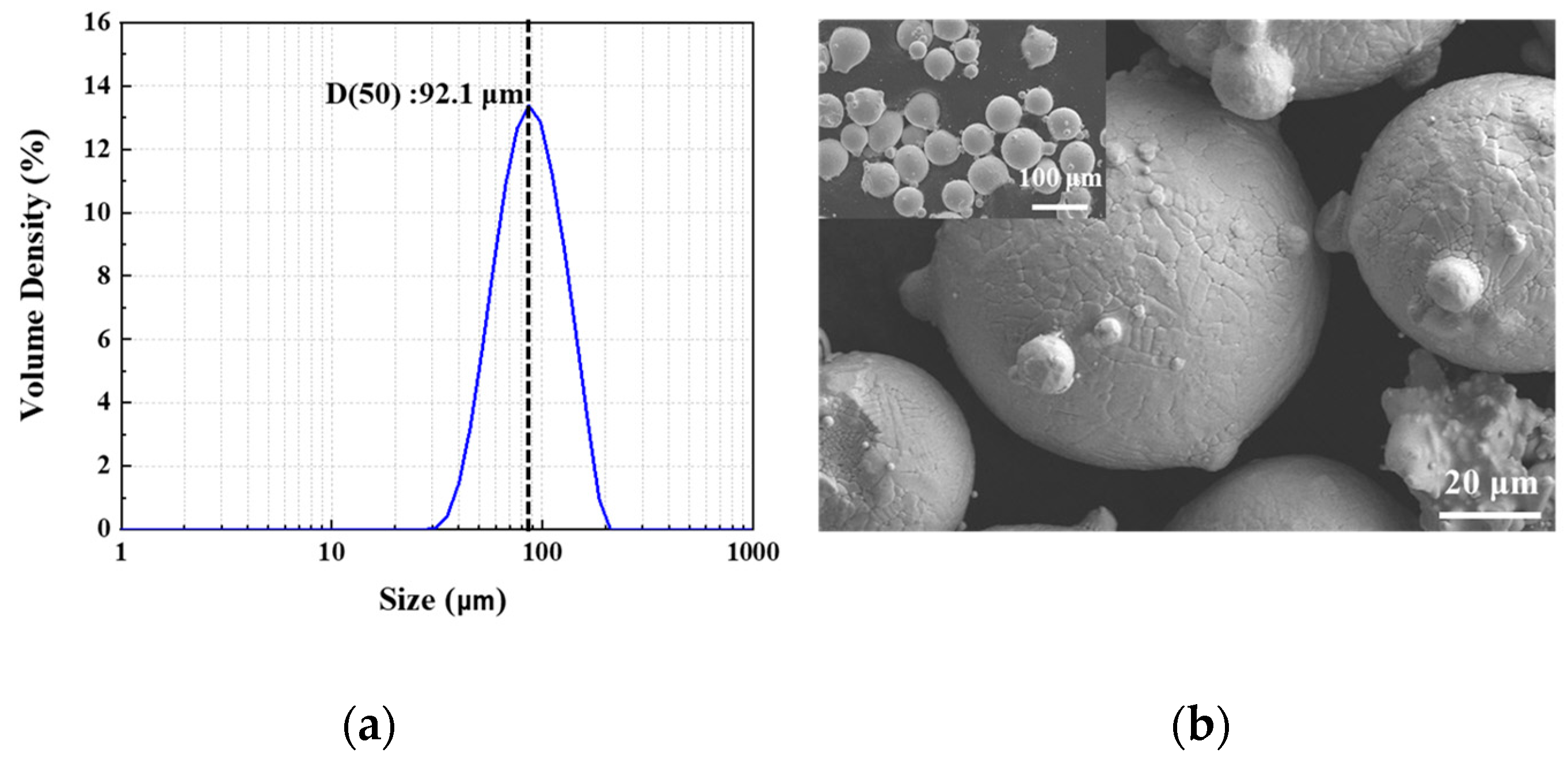
2.1. Powder Properties

In this study, a commercial gas-atomized HX powder (AMC Powders Co. Ltd., Beijing, China) was used, with the alloy composition shown in Table 1. Particle size analysis was conducted using Matersizer 3000 (Malvern Panalytical, Malvern, UK), and the morphology of the powder was observed using scanning electron microscopy (FE-SEM, Hitachi, Tokyo, Japan). It had a spherical morphology, with a particle size range of approximately 57–145 µm (Figure 1). The mean D50 diameter was 92.1 µm. However, some powders had irregular shapes, with small satellites attached to them.

2.2. Direct Energy Deposition (DED) Process

The DED process involves deposition in real time during which a high-power laser beam is directed onto a metal surface, and metal powders are simultaneously fed with the generation of a molten pool. Thus, a metal layer with a dense structure is formed through a rapid melting and cooling process.
The equipment used in this study was a metal DED-type three-dimensional (3D) printer (MX-3, Insstek Inc., Daejeon, Republic of Korea). The laser of the used equipment was 2 kW Yb: YAG (IPG, Oxford, MA, USA), and the laser beam size was set to 1 mm. Powders were supplied through three powder hoppers, and argon was used for coaxial and powder carrier gases to prevent oxidation during the process. Figure 2 shows the DED system used for the deposition of the HX material.
The process experiment was performed with square specimens (10 mm × 10 mm × 5 mm) that were cut in the building direction and used in the microstructure analysis. The optimized process parameters are shown in Table 2.
Tensile and creep specimens were prepared to evaluate their mechanical properties. Furthermore, vertical and horizontal deposition directions were used to verify the differences in mechanical properties according to the building direction. Furthermore, heat treatment was performed to improve porosity and mechanical properties. Three different sample conditions (Table 3) were used: as-built treatment, heat treatment 1 (HT1), and heat treatment 2 (HT2). In the HT1 condition, hot isostatic pressing (HIP) was performed to improve porosity under the following conditions: 1150 °C, 4 h, and 100 MPa. In the HT2 condition, after HIP, solution heat treatment was additionally performed at 1177 °C for 30 min (solution heat treatment, SHT) in specimens to improve their properties.

2.3. Microstructure Evaluation

For microstructure evaluation, the samples were ground and polished with 3 and 0.25 µm diamond suspensions. Thereafter, the prepared sample surface was immediately etched with a mixed solution consisting of 5 g CuCl2 in 100 mL HCl and 100 mL CH3CH2OH (Kalling’s No.2 reagent). Finally, the microstructure was observed using optical microscopy (OM, Axio Observer. D1m, Carl Zeiss, Oberkochen, Germany) and scanning electron microscopy (SEM, JXA-8530F, JEOL, Tokyo, Japan). X-ray diffraction (XRD) was performed using an X-ray diffractometer (SmartLab, RIGAKU, Tokyo, Japan), in which Cu Kα1 radiation was used, and the 2θ range was set from 20° to 100°. Electron backscattered diffraction (EBSD) analyses were performed using an FEI Quattro ESEM system (Thermo Fisher, Waltham, MA, USA) equipped with a Bruker QUANTAX EBSD detector at an acceleration voltage of 20 kV, a step size of 0.12 μm, and a working distance of 19.5 mm.

2.4. Evaluation of Mechanical Properties

As shown in Figure 3a, specimens for tensile and high-temperature creep tests were fabricated under the proposed optimal conditions of DED. The cube-shaped specimens were manufactured in vertical and horizontal directions to confirm anisotropy. The deposited specimens were processed into tensile and creep specimens using wire cutting. Tensile tests were conducted at room temperature (24 °C) with a strain rate of 8.0 × 10⁻⁴/s for the as-built, HT1, and HT2 specimens fabricated in accordance with the ASTM E8 standard, as shown in Figure 3b (Z60, Zwick Roell, Ulm, Germany). Furthermore, tensile tests were conducted at a high temperature (816 °C) with a strain rate of 8.0 × 10⁻⁴/s using the specimens fabricated in the same way. The high-temperature creep test specimens were fabricated in accordance with the ASTM E8 standard, as shown in Figure 3c, and tests were conducted under the conditions of 816 °C, 103 MPa, and an Ar environment according to the ASTM E139-11 test standard (RB 305, R&B, Daejeon, Republic of Korea).

3. Results and Discussion

3.1. Microstructure

As shown in Figure 4, the OM was used to detect the vertical cross-sectional porosity of the as-built and heat-treated specimens manufactured under optimal process conditions. Furthermore, the porosity was reduced after heat treatment, compared with the as-built specimen. The results of the cross-sectional porosity, maximum pore size, and pore number of the samples for each condition are summarized in Table 4. The cross-sectional porosity of the as-built specimens was 0.043%, whereas those of HT1 and HT2 specimens were 0.004% and 0.003%, respectively. The as-built specimens had spherical pores, which were assumed to have been generated from the gas trapped during the process. However, it was confirmed that the residual pores of the as-built specimens were significantly reduced after both heat treatments (HT1 and HT2), and the maximum pore size also decreased.
The cast HX alloy solidified relatively slowly, exhibiting a typical dendritic structure and coarse precipitates [25]. However, during the DED process, a complex microstructure was formed owing to the rapid melting and solidification process. The microstructures of the HX specimens fabricated through the DED process were observed, as shown in Figure 5. The microstructure of the as-built specimen exhibited a boundary of the molten pool (Figure 5a), which was generated due to the laser scan path during deposition. Additionally, the SEM images show the fine cell/columnar structure inside molten pool boundaries. The 3D structure of the cellular structure was similar to a honeycomb and was found to have different shapes depending on the direction of observation [26]. When observed transversely to the cell growth direction, an equiaxed cell structure was observed, and when observed in parallel to the cell growth direction, an elongated rod-type columnar structure was observed.
In the HT1 specimen, almost all the residual pores and dendrite structure disappeared, and recrystallized grains were formed through heat treatment, while film-shaped carbides were formed along the grain boundary, as shown in Figure 5b,e. In the case of the HT1 specimen subjected to isostatic pressure for a relatively long time, Cr-rich M23C6 carbide precipitated in the form of a film along the grain boundary. Conversely, in the HT2 specimen, with the addition of SHT, equiaxed grains were formed, and globular and square inter-/intragranular carbides were generated in the HT2 specimen, as shown in Figure 5c,f. Even after heat treatment, the molten pool boundary did not completely disappear. The existence of the molten pool boundary caused mechanical property anisotropy along the vertical/horizontal building direction.
SEM and EDS analyses confirmed the formation of Cr-rich M23C6 carbide at the grain boundary and inside the grains of the HT-1 and HT2 specimens, which underwent post-heat treatment. According to the literature, the secondary phases that can be generated in HX are carbides (M6C and M23C6), σ, and μ phases [1,27]. However, the only precipitates inside the γ matrix of HX are carbides, unless aging is performed for an extended period [28]. Figure 6 shows the XRD patterns of the HX alloy’s cross-sectional surface in the as-built and heat-treated samples. In the XRD patterns, the characteristic peaks of (1 1 1), (2 0 0), (2 2 0), (3 1 1), and (2 2 2) of γ phase nickel alloy with an FCC (face-centered cubic) crystal structure were detected. Low-intensity peaks associated with the carbide phase were also observed. These peaks can be attributed to M23C6 carbide dispersed in the γ matrix, as mentioned previously.
To confirm the grain size for each specimen, EBSD analysis was performed, and the results are shown in Figure 7. The grain size of the HT2 specimen was determined to be 217 µm based on the EBSD analysis. The grains of the as-built specimens were formed in a direction parallel to the building direction, which was the temperature-gradient direction. In the case of HT1 specimens subjected to isostatic pressure at a high temperature, recrystallization occurred, and it was confirmed that equiaxed grains were formed in HT2 specimens after SHT. This difference in grain shape caused variation in the mechanical properties depending on the building direction. The average grain size of each specimen was as follows: as-built (184 µm), HT1 (125 µm), and HT2 (217 µm). The grain size of the HT2 specimen was coarser than that of the HT1 specimen, at 125 µm. This indicates that, although the exposure to heat at 1177 °C for 30 min was sufficient for grain formation, it was not adequate to completely eliminate the molten pool boundary (MPB). Therefore, the heat treatment time was significantly short.

3.2. Tensile Properties

Figure 8 shows the results of tensile tests at room and high temperatures in as-built, HT1, and HT2 conditions with a vertical direction. In the room temperature test, the as-built specimen had a tensile stress of approximately 693 MPa and a uniform elongation of approximately 52.4%. After heat treatment, the tensile strength values of HT1 and HT2 were similar, but the yield strength significantly decreased (by approximately 228 MPa). However, elongation did not increase significantly.
Moreover, the high-temperature tensile test results revealed that the as-built specimen and the post-heat-treated specimen had similar tensile strength, but the yield strength decreased significantly (by approximately 90 MPa) after heat treatment (HT1 and HT2). However, although the elongation of the as-built specimen at a high temperature significantly decreased to 19%, elongation in HT1 and HT2 specimens significantly increased to 49% and 89%, respectively.
In contrast to the raw material, the HX specimen fabricated using AM had an MPB (Figure 5). Epitaxial growth caused a strong morphological texture in the building direction. Consequently, grains were formed and elongated in the vertical direction in the cross-sectional microstructure of the deposited specimen, as shown in Figure 7a. Moreover, cellular subgrains appeared in the grains. This cellular structure consists of high-density dislocation walls that act as dislocation barriers, significantly increasing the yield strength and hardness of the materials [11,24]. According to the literature, Mo-rich carbides appear in additively manufactured HX specimens [29]. However, in this study, Mo-rich carbides did not appear, and only Cr-rich carbides were observed after heat treatment.
As-built, HT1, and HT2 conditions affected the mechanical properties according to microstructural differences. As shown in Table 5, as-built specimens had a higher yield strength at room temperature. This is caused by high-density dislocation at subgrain boundaries. Conversely, HT1 and HT2 specimens revealed lower yield strength values than as-built specimens owing to the lower dislocation density resulting from the formation of recrystallized grains during heat treatment. The presence of Cr-rich M23C6 carbides along the grain boundaries and within the grains was also confirmed. After heat treatment, tensile strength and elongation values were similar to those of the raw material.
The high-temperature tensile test results indicated that yield strength (YS) and ultimate tensile strength (UTS) decreased. According to the literature, this can be attributed to the decrease in the dislocation density as the sample is exposed to a higher temperature during testing [11]. In high-temperature tensile strength testing, grain boundary sliding (GBS) acts as a major factor causing fracture owing to the dislocation motion near grain boundaries [30]. Therefore, the larger the grain size, the higher the high-temperature strength. However, the as-built specimen showed the highest yield strength owing to the high dislocation density within the grain boundaries, even though the grain size was smaller than that of the HT2 specimen. Comparing the elongation of the different conditions, the HT2 specimen showed the highest elongation value. As shown in Figure 5f, discontinuous carbides were formed at the grain boundary, which suppressed dislocation movement along the grain boundary, resulting in high elongation.
Table 5 summarizes the tensile test results at room and high temperatures in vertical and horizontal directions. The anisotropy of mechanical properties according to the building direction appeared in all three conditions (as-built, HT1, and HT2). This anisotropy according to the building direction was caused by the molten pool boundaries generated in the microstructure of the as-built specimen (Figure 5). When fabricated in the vertical direction, the MPB was in the vertical direction at which the tensile force was applied, as shown in Figure 3a. The MPB of the vertical AM specimen also acted as a crack-propagation path because the cracks causing the fracturing of the specimen were formed in the vertical direction at which the tensile force was applied. In contrast, the horizontal AM specimen interfered with the propagation of cracks because the MPB was formed in the horizontal direction at which the tensile force was applied [31,32,33,34]. The strength of the horizontal specimen was higher than that of the vertical specimen, whereas the elongation showed the opposite result. In the case of the HT1 specimen, recrystallization commenced as the cell/columnar structures were removed, but the recrystallization process remained incomplete. In the case of the HT2 specimen, anisotropy according to the building direction was eliminated because, despite the remaining molten pool boundaries, equiaxed grains were uniformly generated throughout the specimen as recrystallization proceeded. When the results were compared based on the building direction, the HT2 specimen showed the lowest anisotropy effect, and the tensile properties of the HT2 specimens were the most similar to those of the raw material.

3.3. Analysis of High-Temperature (816 °C) Creep Rupture Behavior

Figure 9 shows the high-temperature creep test results according to the building direction for as-built, HT1, and HT2 conditions. The result of the high-temperature creep test showed different creep properties according to the building direction and heat treatment. With respect to the creep property, the rupture time of the vertical direction in the as-built condition was 33 h, approximately 83% larger than that of the horizontal direction (18 h).
Regarding the high-temperature creep property, GBS was the primary cause of the rupture. For the as-built specimens, grains were formed parallel to the building direction as a result of which heat was released. The specimen fabricated in the vertical direction exhibited a higher creep life than that built in the horizontal direction because the area of GBS was minimized by the vertically elongated grains. The columnar grain morphology caused the anisotropy of the creep properties in both specimens. In the horizontal specimen, the grain boundary was aligned normally to the loading axis, reducing the creep life [35]. In addition, as no carbide was present at the grain boundary, the voids adhered to each other when deformed at high temperatures, resulting in excessive GBS. Consequently, the as-built creep life was low.
After heat treatment, the dendritic structure began to disappear, and equiaxed grains and carbides appeared. This study confirmed that the specimen of HT2 with a large grain size had the best creep properties after heat treatment (V: 91 h, H: 114 h). The grain formation due to heat treatment minimized the area of the grain boundary. Moreover, as carbide was unevenly distributed at the grain boundary, the grain boundary was strengthened, and the creep life improved [36,37,38]. However, as mentioned in Section 3.1, the homogenization of the microstructure was not sufficiently advanced; thus, the creep property still had anisotropy.
Figure 10 shows the fracture surface observed through SEM after the creep test. In the as-built specimen, a fracture along the dendritic structure was observed, as shown in Figure 10a. The fracture occurred in the “track–track” MPB region because the interdendritic fracture surface sloped into a structure resembling a “valley.” In contrast, dimples, a typical ductile fracture mode, were observed in the heat-treated specimens.
From the high-temperature creep test results, the HT2 specimen exhibited the best creep properties among the as-built, HT1, and HT2 conditions.

4. Conclusions

In this study, the optimized processing conditions for Hastelloy X alloy using the DED process were proposed, and changes in the microstructure and mechanical properties before and after heat treatment were compared. The results of this study are as follows:
(1) In the as-built specimens, spherical pores were generated owing to the trapped gas during the DED process. However, the residual pores significantly decreased after heat treatment. As-built specimens had a fine cell/columnar structure. After heat treatment, recrystallization occurred as the temperature increased, equiaxed grains were formed, and Cr-rich M23C6 carbides were generated in the γ matrix.
(2) At room temperature, the as-built specimens exhibited a high tensile strength because of the high-density dislocation at subgrain boundaries. Conversely, HT1 and HT2 specimens showed a lower yield strength than as-built specimens because of a lower dislocation density as recrystallized grains were formed because of heat treatment. The high-temperature tensile tests indicated that YS and UTS decreased.
(3) The anisotropy of mechanical properties according to the building direction appeared in all three conditions (as-built, HT1, and HT2). The strength of the horizontal specimen was higher than that of the vertical specimen, and elongation showed the opposite result. When the results were compared according to the building direction, the HT2 specimen showed the lowest anisotropy effect, and the tensile properties of the HT2 specimen were the most similar to those of the raw material.
(4) GBS is the main cause of failure in high-temperature creep properties. For the as-built specimen, grains were formed parallel to the building direction as a result of which heat was released. The specimen fabricated in the vertical direction exhibited a higher creep life than that built in the horizontal direction because the area of GBS was minimized by the vertically elongated grains. After heat treatment, the dendritic structure began to disappear, and equiaxed grains and carbides appeared. This study confirmed that the HT2 specimen with a large grain size had the best creep properties after heat treatment.
(5) The MPB did not completely disappear even after HT2, because a temperature of 1177 °C for 30 min for SHT was not sufficient. Furthermore, anisotropy did not completely disappear in the high-temperature creep results.
(6) These research results highlight the superior high-temperature properties of Hastelloy X material that can be obtained using the DED process. However, further research is needed to completely eliminate anisotropy.

Author Contributions

Conceptualization, Y.-S.L. and J.-H.S.; methodology Y.-S.L. and J.-H.S.; validation, J.-H.S.; investigation, Y.-S.L. and J.-H.S.; data curation, Y.-S.L.; writing—original draft preparation, Y.-S.L.; writing—review and editing, Y.-S.L. and J.-H.S.; visualization, Y.-S.L.; supervision, J.-H.S.; project administration, J.-H.S. All authors have read and agreed to the published version of the manuscript.

Funding

This work was supported by the Korea Institute of Energy Technology Evaluation and Planning (KETEP) and the Ministry of Trade, Industry, and Energy (MOTIE) of the Republic of Korea (No. 20206700000010).

Institutional Review Board Statement

Not applicable.

Informed Consent Statement

Not applicable.

Data Availability Statement

Not applicable.

Conflicts of Interest

The authors declare no conflict of interest.

References

  1. Zhao, J.C.; Larsen, M.; Ravikumar, V. Phase precipitation and time–temperature-transformation diagram of Hastelloy X. Mater. Sci. Eng. A 2000, 293, 112–119. [Google Scholar] [CrossRef]
  2. Haynes-International. Hastelloy X Alloy; Haynes-International: Kokomo, IN, USA, 1997; Volume 16. [Google Scholar]
  3. Hong, H.U.; Kim, I.S.; Choi, B.G.; Jeong, H.W.; Jo, C.Y. Effects of temperature and strain range on fatigue cracking behavior in Hastelloy X. Mater. Lett. 2008, 62, 4351–4353. [Google Scholar] [CrossRef]
  4. Harrison, N.J.; Todd, I.; Mumtaz, K. Reduction of micro-cracking in nickel superalloys processed by selective laser melting: A fundamental alloy design approach. Acta Mater. 2015, 94, 59–68. [Google Scholar] [CrossRef]
  5. Wilson, J.M.; Piya, C.; Shin, Y.C.; Zhao, F.; Ramani, K. Remanufacturing of turbine blades by laser direct deposition with its energy and environmental impact analysis. J. Clean. 2014, 80, 170–178. [Google Scholar] [CrossRef]
  6. Trojan, K.; Ocelík, V.; Capek, J.; Cech, J.; Canelo-Yubero, D.; Ganev, N.; Kolarík, K.; De Hosson, J.T.M. Microstructure and Mechanical Properties of Laser Additive Manufactured H13 Tool Steel. Metals 2022, 12, 243. [Google Scholar] [CrossRef]
  7. Cao, L.; Zhang, L.; Bi, G. Feasibility Study on Deposition of Tribaloy T800 on Cobalt-Based L605 Using Micro-Laser-Aided Additive Manufacturing. Metals 2022, 12, 586. [Google Scholar] [CrossRef]
  8. Vu, H.M.; Meiniger, S.; Ringel, B.; Hoche, H.C.; Oechsner, M.; Weigold, M.; Schmitt, M.; Schlick, G. Investigation of Material Properties of Wall Structure from Stainless Steel 316L Manufactured by Laser Powder Bed Fusion. Metals 2022, 12, 285. [Google Scholar] [CrossRef]
  9. Aversa, A.; Marchese, G.; Bassini, E. Directed Energy Deposition of AISI 316L Stainless Steel Powder: Effect of Process Parameters. Metals 2021, 11, 932. [Google Scholar] [CrossRef]
  10. Wang, F. Mechanical property study on rapid additive layer manufacturing Hastelloy X alloy by selective laser melting technology. Int. J. Adv. Manuf. Technol. 2012, 58, 545–551. [Google Scholar] [CrossRef]
  11. Montero-Sisroaga, M.L.; Liu, Z.; Bautmans, L.; Nardone, S.; Ji, G.; Kruth, J.-P.; Van Humbeeck, J.; Vanmeensel, K. Effect of temperature on the microstructure and tensile properties of micro-crack free hastelloy X produced by selective laser melting. Addit. Manuf. 2020, 31, 100995. [Google Scholar] [CrossRef]
  12. Marchese, G.; Bassini, E.; Aversa, A.; Lombardi, M.; Ugues, D.; Fino, P.; Biamino, S. Microstructural Evolution of Post-Processed Hastelloy X Alloy Fabricated by Laser Powder Bed Fusion. Materials 2019, 12, 486. [Google Scholar] [CrossRef] [PubMed]
  13. Li, Y.; Qi, H.; Hou, H.; Lei, L. Effects of Hot Isostatic Pressing on Microstructure and Mechanical Properties of Hastelloy X Samples Produced by Selective Laser Melting. Adv. Eng. Res. 2017, 102, 31–40. [Google Scholar] [CrossRef]
  14. Zhang, S.; Liu, J.; Lin, X.; Huang, Y.; Zhang, Y.; Guo, P.; Li, J.; Huang, W. Microstructure and anodic electrochemical behavior of additive manufactured Hastelloy X alloy via directed energy deposition. Addit. Manuf. 2021, 39, 101824. [Google Scholar] [CrossRef]
  15. Xu, L.; Gao, Y.; Zhao, L.; Han, Y.; Jing, H. Ultrasonic micro-forging post-treatment assisted laser directed energy deposition approach to manufacture high-strength Hastelloy X superalloy. J. Mater. Process. Technol. 2022, 299, 117324. [Google Scholar] [CrossRef]
  16. Mahamood, R.M.; Akinlabi, E.T.; Shukla, M.; Pityana, S. Laser Metal Deposition of Ti6Al4V: A Study on the Effect of Laser Power on Microstructure and Microhardness. In Proceedings of the International MultiConference of Engineering and Computer Scientists (ICMCS 2013), Hong Kong, China, 13–15 March 2013. [Google Scholar]
  17. Kim, J.S.; Kang, B.J.; Lee, S.W. An experimental study microstructure characteristics and mechanical properties of stainless-steel 316L parts using directed energy deposition (DED) process. J. Mech. Sci. Technol. 2019, 33, 5731–5737. [Google Scholar] [CrossRef]
  18. Mathoho, I.; Akinlabi, E.T.; Arthur, N.; Tlotleng, M. Impact of DED process parameters on the metallurgical characteristics of 17-4PH SS deposited using DED. CIRP J. Manuf. Sci. Technol. 2020, 31, 450–458. [Google Scholar] [CrossRef]
  19. Jinoop, A.N.; Paul, C.P.; Bindra, K.S. Laser assisted direct energy deposition of Hastelloy X. Opt. Laser Technol. 2019, 109, 14–19. [Google Scholar] [CrossRef]
  20. Woo, I.Y.; Lyu, M.Y. Variations in the Impact strength of material extrusion-type 3D printed specimens depending on tool path and building direction. Polym. Korea 2020, 44, 471–478. [Google Scholar] [CrossRef]
  21. Carroll, B.E.; Palmer, T.A.; Beese, A.M. Anisotropic tensile behavior of Ti-6Al-4V components fabricated with directed energy deposition additive manufacturing. Acta Mater. 2015, 87, 309–320. [Google Scholar] [CrossRef]
  22. Hrabe, N.; Gnäupel-Herold, T.; Quinn, T. Fatigue properties of a titanium alloy (Ti–6Al–4V) fabricated via electron beam melting (EBM): Effects of internal defects and residual stress. Int. J. Fatigue 2017, 94, 202–210. [Google Scholar] [CrossRef]
  23. Qiu, C.; Adkins, N.J.E.; Attallah, M.M. Microstructure and tensile properties of selectively laser-melted and of HIPed laser-melted Ti–6Al–4V. Mater. Sci. Eng. A 2013, 578, 230–239. [Google Scholar] [CrossRef]
  24. Tomus, D.; Tian, Y.; Rometsch, P.A.; Heilmaier, M.; Wu, X. Influence of post heat treatment on anisotropy of mechanical behavior and microstructure of Hastelloy-X parts produced by selective laser melting. Mater. Sci. Eng. A 2016, 667, 42–53. [Google Scholar] [CrossRef]
  25. Choi, B.G.; Kim, I.S.; Do, J.H.; Jung, J.E.; Jung, I.Y.; Hong, H.U.; Jo, C.Y. The Effect of Thermal Exposure on the Microstructural Evolution and Tensile Properties in Cast Hastelloy X. J. Korea Foundry Soc. 2017, 37, 139–147. [Google Scholar] [CrossRef]
  26. Kong, D.; Dong, C.; Wei, S.; Ni, X.; Zhang, L.; Li, R.; Wang, L.; Man, C.; Li, X. About metastable cellular structure in additively manufactured austenitic stainless steels. Addit. Manuf. 2021, 28, 101804. [Google Scholar] [CrossRef]
  27. Jiang, L.; Hu, R.; Kou, H.; Li, J.; Bai, G.; Fu, H. The effect of M23C6 carbides on the formation of grain boundary serration in a wrought Ni-based superalloy. Mater. Sci. Eng. A 2012, 536, 37–44. [Google Scholar] [CrossRef]
  28. Tawancy, H.M. Long-term ageing characteristics of Hastelloy alloy X. J. Mater. 1983, 18, 2976–2986. [Google Scholar] [CrossRef]
  29. Marchese, G.; Basile, G.; Bassini, E.; Aversa, A.; Lombardi, M.; Ugues, D.; Fino, P.; Biamino, S. Study of the microstructure and cracking mechanisms of hastelloy X Produced by laser powder bed fusion. Materials 2018, 11, 106. [Google Scholar] [CrossRef]
  30. Jang, J.E.; Kim, Y.S.; Sung, J.H.; Kim, Y.J.; Park, S.H.; Kim, D.H. Microstructural control strategy based on optimizing laser powder bed fusion for different Hastelloy X powder size. Materials 2022, 15, 6191. [Google Scholar] [CrossRef]
  31. Syed, A.K.; Ahmad, B.; Guo, H.; Machry, T.; Eatock, D.; Meyer, J.; Fitzpatrick, M.E.; Zhang, X. An experimental study of residual stress and direction-dependence of fatigue crack growth behaviour in as-built and stress-relieved selective-laser-melted Ti6Al4V. Mater. Sci. Eng. A 2019, 755, 246–257. [Google Scholar] [CrossRef]
  32. Wauthle, R.; Vrancken, B.; Beynaerts, B.; Jorissen, K.; Schrooten, J.; Kruth, J.-P.; Van Humbeeck, J. Effects of build orientation and heat treatment on the microstructure and mechanical properties of selective laser melted Ti6Al4V lattice structures. Addit. Manuf. 2015, 5, 77–84. [Google Scholar] [CrossRef]
  33. Tao, P.; Li, H.-X.; Huang, B.-Y.; Hu, Q.-D.; Gong, S.-L.; Xu, Q.-Y. Tensile behavior of Ti-6Al-4V alloy fabricated by selective laser melting: Effects of microstructures and as-built surface quality. China Foundry 2018, 15, 243–252. [Google Scholar] [CrossRef]
  34. Mahmud, A.; Huynh, T.; Zhou, L.; Hyer, H.; Mehta, A.; Imholte, D.D.; Woolstenhulme, N.E.; Wachs, D.M.; Sohn, Y. Mechanical Behavior Assessment of Ti-6Al-4V ELI Alloy Produced by Laser Powder Bed Fusion. Metals 2021, 11, 1671. [Google Scholar] [CrossRef]
  35. Banoth, S.; Palleda, T.N.; Saito, T.; Murakami, H.; Kakehi, K. Effect of yttrium and silicon contents in Hastelloy-X built by selective laser melting process. J. Alloys Compd. 2022, 896, 163050. [Google Scholar] [CrossRef]
  36. Thébaud, L.; Villechaise, P.; Crozet, C.; Devaux, A.; Béchet, D.; Franchet, J.M.; Rouffie, A.L.; Mills, M.; Cormier, J. Is there an optimal grain size for creep resistance in Ni-based disk superalloys? Mater. Sci. Eng. A 2018, 716, 274–283. [Google Scholar] [CrossRef]
  37. Bang, J.H.; Kang, Y.J.; Kim, N.K.; Seo, S.M.; Lee, S.H.; Song, S.W.; Kang, N.H. Effect of aging heat treatment conditions on the mechanical properties and microstructure of base and weld metal of alloy 282 superalloy. Korean J. Met. Mater. 2020, 8, 540–549. [Google Scholar] [CrossRef]
  38. Wang, L.; Wang, D.; Liu, T.; Li, X.W.; Jiang, W.G.; Zhang, G.; Lou, L.H. Effect of minor carbon additions on the high-temperature creep behavior of a single-crystal nickel-based superalloy. Mater. Char. 2015, 104, 81–85. [Google Scholar] [CrossRef]
Figure 1. Hastelloy X (HX) powder for direct energy deposition (DED): (a) particle size distribution HX powder; (b) SEM image of gas-atomized HX powder showing spherical shapes.
Metals 13 00885 g001
Figure 2. DED system used for the deposition of Hastelloy X alloy.
Metals 13 00885 g002
Figure 3. Specimens for testing mechanical properties: (a) schematics of the HX samples according to the building direction and scanning strategy; (b) tensile test specimen specification; (c) creep test specimen specification.
Metals 13 00885 g003aMetals 13 00885 g003b
Figure 4. Cross-sectional porosity results of Hastelloy X in the building direction plane: (a) as-built, (b) HT1, and (c) HT2.
Metals 13 00885 g004
Figure 5. Optical micrographs and SEM images of HX specimens in the building direction plane: (a,d) as-built; (b,e) HT1; (c,f) HT2.
Metals 13 00885 g005
Figure 6. X-ray diffraction (XRD) patterns of as-built, HT1, and HT2 samples.
Metals 13 00885 g006
Figure 7. Electron backscatter diffraction (EBSD) results of HX specimens in the building direction plane (vertical): (a,d) as-built; (b,e) HT1; (c,f) HT2.
Metals 13 00885 g007
Figure 8. Stress–strain curves of the Hastelloy X alloy post-heat treatment in comparison to the as-built sample (vertical direction): (a) room temperature (24 °C); (b) high temperature (816 °C).
Metals 13 00885 g008
Figure 9. Creep test results according to the building direction: (a) as-built; (b) heat treatment.
Metals 13 00885 g009
Figure 10. Creep fracture surface morphology of Hastelloy X specimens at various magnifications: (a,b) as-built; (c,d) HT1.
Metals 13 00885 g010
Table 1. Chemical composition of Hastelloy X.
Element (wt%)NiCrFeMoWCoCSiMn
Powder HXBal.21.319.18.60.650.960.070.160.54
Table 2. DED process parameters for Hastelloy X alloy.
Power
(W)
Scanning Speed
(m/min)
Powder Feeding Rate
(g/min)
Overlap
Ratio
(%)
Layer Thickness
(mm)
4500.853.5600.25
Table 3. Summary of the three testing conditions.
SpecimenAs-BuiltHT1HT2
ConditionsAs-built1150 °C, 4 h, 100 MPa
(Furnace cooling)
1150 °C, 4 h, 100 MPa
+
1177 °C, 30 min
(N2 gas cooling)
Table 4. Porosity measurement results of cross-sectional specimens.
SpecimenAs-BuiltHT1HT2
Cross-sectional porosity (%)0.0430.0040.003
Maximum pore size (μm)93.62627.56311.666
Tracked Pore number711219
Table 5. Tensile test results of the as-built, HT1, and HT2 Hastelloy X specimens with different building directions: horizontal direction (H) and vertical direction (V).
SpecimenR.T. (24 °C)H.T. (816 °C)
Y.S
(MPa)
UTS
(MPa)
Elongation
(%)
Y.S
(MPa)
UTS
(MPa)
Elongation
(%)
Raw324 ± 1.4739.5 ± 4.953.3 ± 2.8210.5 ± 21.9343 ± 1.467.2 ± 0.4
As
-built
H508 ± 0.0566 ± 1.45.75 ± 1.1244 ± 0.0312.5 ± 2.13.5 ± 3.5
V524.5 ± 27.6693 ± 26.952.4 ± 2.1259.5 ± 3.5328 ± 1.419.4 ± 2.3
HT1H361.5 ± 9.2796.5 ± 4.930 ± 1.4214.5 ± 0.7348 ± 2.828.5 ± 3.5
V296.5 ± 46.0672.5 ± 43.150.3 ± 0.7166.5 ± 2.1305.5 ± 0.749.2 ± 1.5
HT2H311 ± 9.9758 ± 4.248.7 ± 7.2197 ± 1.4333.5 ± 3.596.6 ± 11.3
V294.5 ± 0.7695.5 ± 50.257 ± 7.3185 ± 0.0309 ± 4.288.9 ± 37.3
Disclaimer/Publisher’s Note: The statements, opinions and data contained in all publications are solely those of the individual author(s) and contributor(s) and not of MDPI and/or the editor(s). MDPI and/or the editor(s) disclaim responsibility for any injury to people or property resulting from any ideas, methods, instructions or products referred to in the content.

