Abstract
Currently, additive manufacturing technologies for materials and products are being implemented and improved. This is due to the possibility of creating workpieces with complex geometric shapes and specified functional gradient properties. The materials with the most complex functional properties demanded by the military–energy industry include bimetals of the “low-alloyed carbon steel—stainless chromium-nickel steel” type. One of the promising ways to obtain bimetallic products is the WAAM (Wire Arc Additive Manufacturing) technology. Despite the large scientific groundwork, the composition, structure, and properties of bimetallic composites produced by WAAM have not been sufficiently studied. The aim of the current work is to study the effect of WAAM parameters and the subsequent heat treatment on the composition, structure, and physical and mechanical properties of the bimetallic composite “ER70S-6-R309LSI”. Spectral, metallographic, and X-ray diffraction studies were carried out, as were mechanical tests of the samples obtained under various WAAM modes. In order to improve the composites’ properties, various types of heat treatments were applied. It is shown that the WAAM modes, the building strategy, and heat treatment determine the structure of layers and transition zones, as well as the mechanical characteristics of the composite. The structure of ER70S-6 in the composite is represented by the ferrite and the ferrite–cementite mixture (pearlite), and ER309LSI is represented by different ratios of austenite, δ-ferrite, carbide, and intermetallic phases. From the point of view of the mechanical properties, the most promising mode of surfacing is “Double Pulse”, followed by heat treatment by way of austenitization and normalization annealing. In this case, there is a decrease in the content of the δ-ferrite, a leveling of microhardness values, and a 40% increase in the tensile strength of the composite.
1. Introduction
Currently, experimental and industrial additive technologies for the production of materials and products are being actively developed. It happens due to the unique technological possibilities for obtaining workpieces with complex shapes, including ones made of polymetallic composite materials with specified functional gradient properties.
For this reason, there are more and more studies devoted to both the physical and technological aspects of products’ additive growth and the evaluation of the obtained materials’ properties [1,2,3,4,5,6,7,8,9]. Thus, in [1], the fundamentals of laser beam melting, electron beam melting, and laser metal deposition are described, and publicly available materials for various processes are also presented. The results stated in [2,3] show the superiority of the corrosion-fatigue characteristics of alloys obtained using additive technologies in comparison with casting.
The authors in the work [4] show that for each layer of deposition, the Marangoni force plays the most important role in affecting fluid flow, and conduction is the dominant method of heat dissipation compared with convection and radiation to the air. As the layer number increases, the length and width of the molten pool and the width of the deposited bead increase, while the layer height decreases.
Moreover, the use of additive technologies is accompanied by the formation of various defects, such as deformation, porosity, and cracking. In the manuscripts [5,6,8], methods for improving the quality of manufacturing parts and assemblies using WAAM are discussed. The authors conclude that the widespread use of WAAM is still associated with many problems, and they may need to be solved in specific ways for different materials in order to create a workable system in an acceptable time frame. Integration of materials and manufacturing processes to produce defect-free and structurally reliable welded parts remains the most important challenge for the future.
The authors in the work [7] propose the use of “replicative” structures in different sizes and orders of magnitude to manufacture parts with the minimum weight while achieving the required mechanical properties.
The work [9] is devoted to the effect of heat treatment on the structure and physico-mechanical properties of various steels obtained by the method of additive technologies. The authors show that the properties of steels obtained using additive technologies are superior to those of traditional steels or, conversely, that their properties are lagging behind.
Traditionally, two additive manufacturing technologies that differ in the way the material is resupplied into the shaping zone are distinguished [10]: powder bed fusion (PBF) and directed deposition (DED). The first technology is based on the stage-by-stage melting of the powder located on the surface of the table by a focused energy source. This technology assumes complete filling of the chamber with protective gas before fusion [8,10,11,12,13]. The second technology (DED) is implemented with the direct supply of material to the printing zone and the simultaneous formation of a melt [6,8,10,11] in a protective atmosphere.
Among the existing PBF technologies, the method of selective laser melting (SLM) has gained particular popularity [13,14,15,16]. This method is distinguished by the high geometric accuracy of the obtained workpieces, which provides a small allowance for machining and increases the material utilization factor. The main disadvantages of SLM technology include low productivity, relatively small dimensions of the resulting workpieces, and the high cost of the produced products [8,10,17].
The DED technologies allow for the elimination of the disadvantages described above for SLM; however, the shape of the workpieces performed by DED requires significant allowances to obtain the required geometry parameters by machining. The most popular DED technologies include laser alloying with wire or powder feeding, electric arc cladding (WAAM), and electric beam cladding with wire [18,19,20,21,22,23,24,25,26,27]. When implementing these methods, it is technologically necessary to apply the operations of mechanical and heat treatment to obtain the final product.
In [18], the authors fabricated walls from 304L stainless steel alloy using WAAM. The obtained samples were subjected to mechanical tests to determine the properties that depend on the orientation of the deposit, as well as microstructural studies to identify features that affect the growth of cracks.
A study of the influence of free and active cooling on the surface roughness of the material of SS308L walls fabricated by the WAAM method is shown in [19].
The authors experimentally determined that walls built with active cooling have a lower surface roughness and a greater layer thickness compared with walls built with free cooling.
The work [21] considers how the gas-electric arc additive manufacturing (GMA-AM) method affects the microstructure and tensile properties of steel 316 L.
In [22], the authors carried out experiments with 316L stainless steel at various arc modes and a constant deposition rate and presented the results, reflecting the mechanism and influence of the arc mode on the stability of the production process, structural integrity, microstructures, and mechanical properties.
A study of the effect of gas tungsten arc welding (GTAW-AM) on the corrosion resistance and microstructure of 316L steel is shown in [23]. The authors concluded that the use of this technology reduces the corrosion resistance of 316L steel and that its use is limited to the manufacture of products from non-rusting steels.
The works [24,25,27] show the features of products obtained by layer-by-layer electron-beam additive manufacturing (EBAM), as well as extensive studies of the physical and mechanical properties of steels obtained by the above method. The authors of [26] obtained interesting results reflecting the effect of heat treatment on the structure and properties of steels obtained by the EBAM method.
From the point of view of industrial implementation and the organization of manufacturing, WAAM technology has significant advantages. This is due to the relatively low cost of equipment and deposited material (compared with laser or electron beam equipment), as well as a sufficient level of understanding of welding processes [28]. In addition, the WAAM technology makes it possible to obtain large-sized workpieces, which is an urgent issue for heavy and power engineering. In [29,30], the advantages of WAAM technology over powder methods are indicated, which consist of the possibility of producing products with the smallest number of defects. The general advantages of DED methods also include the technological possibility of quick replacement of the deposited material, which makes it possible to perform cladding of corrosion-prone areas of products and produce composite materials with functionally graded properties.
Among the surfacing materials used for metal 3D printing, chromium-nickel and low-alloy steels, titanium alloys, and a number of INCONEL-type heat-resistant alloys are the most widely used. However, considering the specifics of complex structural and shaping processes in the implementation of additive manufacturing, there is a need for additional studies of the resulting materials’ composition, structure, and properties.
For example, in [31], the microstructure, mechanical properties, and corrosion resistance of low-alloy steel ER70S-6 samples obtained by the WAAM method were studied. It is shown that the corrosion resistance gained by the WAAM technology samples is not lower than that of samples produced by traditional production methods. An analysis of the microstructure made it possible to reveal the typical structure of low-carbon steel with a low content of the pearlite phase.
A large number of scientific works are devoted to the study of the chromium-nickel steels’ properties obtained by the WAAM method. The structure and phase composition of ASI 300 Group’s steels are researched in [32]. It is shown that the phase composition of steels obtained by additive technologies differs significantly from steels produced by traditional production methods. Depending on the technology used, its parameters, and the chemical composition of the starting material, 3D-printed steels can be characterized by both single-phase and multi-phase structures: austenite, ferrite, carbides, and intermetallic compounds.
The Creq/Nieq ratio has a significant effect on the phase composition of chromium-nickel steels. In this case, the presence of the δ-ferrite phase in the structure of the material is considered a negative factor affecting the mechanical properties and the alloy’s corrosion resistance. The study [33,34] also indicates the presence of structural inhomogeneity along the height of the grown workpieces. This is attributed to the uneven distribution of thermal fields and the solidification process during the cooling of the layers. In this case, a gradient of structure and mechanical properties is formed in the material. The long exposures in the temperature range of the annealing process, which are typical for the lower layers of the deposited workpiece, can improve their mechanical properties.
The specified inhomogeneities of the structure and mechanical properties of the products’ material, obtained by additive technologies such as three-dimensional printing, determine the use of additional deformation and/or heat treatment. In [35], the authors studied the effect of additional rolling of samples produced using the WAAM technology with rollers. It is shown that the use of plastic deformation made it possible to significantly reduce the grain size and residual stresses. In [36,37,38,39], the authors researched the effect of heat treatment on the steel structure after WAAM. It is illustrated that the additional heat treatment can significantly reduce residual stresses in the workpiece, reduce cracking, and homogenize the structure of the material. It is revealed in [40] that the exposure of a workpiece made of austenitic steel at a temperature of 1050 °C caused a twofold decrease in the content of the ferrite phase.
As it was mentioned earlier, the use of additive technologies makes it possible to obtain unique products from multilayer polymetallic compositions of various metals and alloys. The most common and well-studied are compositions consisting of two metallic materials with different structural and physical natures—bimetals. Such composites have a set of properties characteristic of each material and are widely used in the military, energy, and aerospace industries [41,42,43]. The classical technologies for producing polymetallic composite materials include friction stir welding [44,45,46], electron beam welding [47], plasma spraying [48], pressing [49], and diffusion welding [50].
The production of multilayer polymetallic materials from various combinations of materials is known. However, the most common systems are steel, copper, aluminum, nickel, titanium, and magnesium in various mass combinations [51]. Particular attention is paid in these studies to the need to ensure a strong connection between two materials without internal macrodefects (cracks, pores, etc.). The main reasons for that type of defect occurrence include the difference in the physical properties of the joined materials: thermal conductivity, melting temperature, linear expansion coefficient, phase transitions, and various types of crystal lattices. As a rule, during production, a distinctive boundary of materials with a structure, phase composition, and properties different from the base metals is formed in the workpiece [52,53,54,55]. Such a boundary can be considered a significant structural macrodefect in a layered bimetallic composite.
The bimetallic systems based on low-carbon and chromium-nickel steels represent considerable industrial interest. The surface cladding of low-carbon steels with expensive chromium-nickel steels of the AISI 308, 309, and 316 types makes it possible to obtain complex-shaped products with a set corrosion resistance, ductility, and optimal cost. In classical industrial technologies, products with geometrically complex shapes made of stainless chromium-nickel steels are produced by casting or long-term machining of monolithic blanks.
In [56,57,58,59,60], the technology for obtaining such bimetallic composites by the WAAM method was considered. An analysis of the structure made it possible to reveal the mixing of materials at the interface and the emergence of new intermetallic structural components from the side of low-alloy steel. That led to a change in the microhardness of the transition zone and its plastic properties. The studies also indicate the presence of a mutual migration of chemical elements near the transition zone. In particular, the redistribution of Ni and its migration across the boundary into the near-boundary zone of low-carbon steel were noted. Mechanical tests carried out as a part of the following research showed the averaged values of the strength and plastic characteristics for layered bimetallic composites in relation to the properties of the materials included in the system.
Despite the presence of a large number of studies on WAAM production technologies, the structure and physical and mechanical properties of the bimetallic composite ER70S-6-ER309LSI (low-alloy carbon steel—stainless chromium-nickel steel) have not been researched enough. In particular, there is no reliable information about the effect of heat treatment on the structure and mechanical properties of the resulting bimetal. The choice of this material system is associated with the wide use of ER70S-6 and ER309LSI alloys in mechanical engineering [61,62,63,64,65,66,67,68,69].
Taking into account the current scientific groundwork, the purpose of the following study is to research the effect of the WAAM’s technological parameters and subsequent heat treatment on the composition, structure, physical, and mechanical properties of the layered bimetallic composite “ER70S-6-ER309LSI”. The scientific novelty of the work consists in obtaining and substantiating the results of metallographic, X-ray diffraction, and spectral studies of a bimetallic composite’s various zones, as well as determining the values of the tensile strength, relative elongation, and microhardness of this alloy system.
2. Materials and Methods
2.1. Experimental Stand and Materials
The experimental samples from layered composite (bimetal) ER70S-6-R309LS were obtained using a laboratory experimental WAAM machine. The setup included IVCNC STL three-axis CNC machine (Ivanovo, Russia), Alloy 275 ME Pulse welding current source, fume hood, welding table, and welding torch. The stand allows the CNC program to perform 3D printing in automatic mode with the necessary shutter speeds to ensure a set thermal pause between layers. The appearance of the WAAM setup is shown in Figure 1.
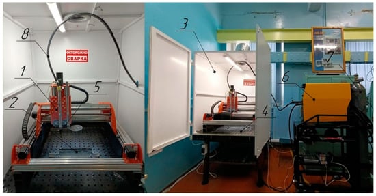
Figure 1.
WAAM setup: 1—CNC portal machine, 2—workpiece during surfacing, 3—fume hood, 4—welding table, 5—extruder, 6—welding machine, 7—cylinder with protective gas, 8—welding channel.
The welding wires ESAB ER70S-6 and ESAB OK AUTROD ER309LSI (ESAB, Saint Petersburg, Russia) with a diameter of 0.8 mm were chosen as the source material for the researched composite. The surfacing was carried out on a substrate made of 09Mn2Si steel (Nizhny Novgorod, Russia) with a thickness of 6 mm. The chemical composition of the used wires and the substrate material is shown in Table 1. The main mechanical characteristics of the welding wires are given in Table 2.

Table 1.
Chemical composition of ER70S-6 and ER309LSI welding wires and substrates.
Table 2.
Mechanical characteristics of the used welding wires.
As a protective atmosphere, a welding mixture of CO2—80% and Ar—20% was used for surfacing with ER70S-6 welding wire, and a mixture of Ar—98% and CO2—2% was used when surfacing with ER309LSI welding wire.
2.2. Modes and Strategy WAAM
The samples for metallographic studies, chemical analysis, and X-ray diffraction analysis were fabricated using a unified printing strategy for various surfacing modes. At the first stage, the surfacing of the walls with welding wire ER70S-6 was carried out according to the shuttle construction scheme. The walls were printed in groups of 8 pieces. The “Double Pulse” mode was chosen as mode of welding power source’s operation because it provides minimal spattering of the weld pool, the lowest heat input, and stability of the deposited layers’ resulting geometry parameters. The following settings were used: the average value of the electric arc current I = 120 A, the average voltage U = 25 V, the pulse frequency of the modulation of the welding current F = 120 Hz, the wire feed speed V = 12.2 m/min, and the speed of the torch relative to the substrate S = 350 mm/min.
The thermal interlayer exposure was used during surfacing. Each subsequent layer was deposited on the previous one and cooled down to 80° Clayer. To control the interlayer temperature, a Guide PS610 thermal imager (Guide Sensmart, Wuchan, China) with automatic filter switching was used: −40–50 °C; 100–800 °C. The achieved measurement accuracy is ±2%. Upon completion of the layer’s formation, the average temperature of the controlled area was measured. When the required value was reached, the printing of the next layer started. The temperature of the layers was controlled using a Guide PS610 thermal imager. Each printed wall consisted of 10 deposited layers.
At the next stage, a group of workpieces was dismantled from the WAAM machine welding table and placed on the table of a CNC GF2171 vertical milling machine (Nizhny Novgorod, Russia) (Figure 2). The mechanical processing of the upper end of the walls was carried out on a milling machine with an end milling cutter in order to form a base surface for further depositing layers of ER309LSI welding wire. Additional machining also made it possible to conduct a preliminary visual inspection of the obtained walls for the presence of macrodefects that can form during surfacing. Upon completion of the milling stage, the wall group was fixed again in the working area of the WAAM machine.
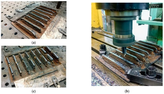
Figure 2.
Technology for manufacturing a layered bimetallic composite ER70S-6-ER309LSI: (a)—wall surfacing with ER70S-6 welding wire; (b)—milling of base surfaces; (c)—surfacing on base surfaces with ER309LSI welding wire.
The subsequent surfacing of layers from ER309LSI welding wire was performed in different modes with different specific surfacing energies (Q), interlayer holding temperatures (Tc), and types of deposited material transfer. In total, a set of 6 unique bimetallic samples was obtained. The deposition modes used for each sample are presented in Table 3. The samples A and B were printed by transferring the electrode material into the weld pool by short circuits at specific energies QA = 0.5 kJ/mm and QB = 0.86 kJ/mm. The samples C and D were printed using the “Double Pulse” mode using small-drop transfer of the electrode material into the weld pool and interlayer thermal modes Tc = 350 °C and Tc = 750 °C. The samples were cooled by forced air convection using the vent system of the WAAM setup. The cooling time of the sample depended on the specific energy of the surfacing, the serial number of the layer, and the type of deposited metal. Average cooling times for ER309LSI layers were: 10 min to 80 °C, 3 min to 350 °C, and 40 s to 750 °C. The countdown started at the beginning of the surfacing process. The sample E was welded using the “Double Pulse” mode and Tc = 80 °C. The walls for subsequent heat treatment were deposited in the "Double Pulse" mode with the previous layer cooling down to 80 °C.
Table 3.
Surfacing modes with ER309LSI welding wire.
After the surfacing of the bimetallic composite ER70S-6-ER309LSI walls, longitudinal and transverse cutting was performed on a band saw machine for the final formation of the researched samples. When cutting samples, an abundant supply of lubricating coolant was used in the cutting zone in order to prevent the effect of the temperature factor on the structure of the fabricated sample.
2.3. Metallographic Studies
At the next stage, the samples for metallographic studies were ground on a special grinding and polishing machine. Step by step, abrasive paper with different grain sizes was used: 120, 240, 400, 600, 800, and 1200. To exclude structural changes due to overheating of the samples, a coolant (water) was used during mechanical grinding. Then the samples were polished using felt polishing discs and special diamond pastes with grits of 3000 and 5000. The final polishing was performed by hand using a velvet cloth and a diamond paste with a grit of 10,000. After polishing, the samples were subjected to a two-stage etching. A 4% alcohol solution of HNO3 was used to etch steel ER70S-6. The process was performed by immersing the polished sample surface in the solution for 10–20 s. After that, a protective composition (clear varnish) was applied to the etched surface of ER70S-6 steel. After drying the protective varnish, the process of electrolytic etching of the polished 309LSI steel surface took place. For that purpose, a 10% aqueous solution of oxalic acid was used in the following modes: 5V, 2A, 30–60 s. After completion of all stages of etching, the protective layer (lacquer) was removed from the surface of ER70S-6 steel using a cotton pad and ethyl alcohol. The study of the microstructure of the samples’ surface (a diagram showing the analyzed zones is shown in Figure 3) was performed on an optical metallographic microscope, “KEYENCE VHX-1000” (KEYENCE, Osaka, Japan).
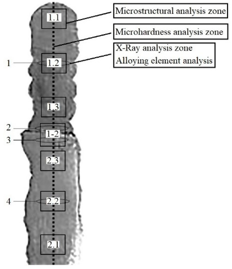
Figure 3.
The scheme of vertical walls in the studies: 1.1—upper zone ER309LSI; 1.2—middle zone ER309LSI; 1.3—boundary zone ER309LSI; 2.1—lower zone ER70S-6; 2.2—middle zone ER70S-6; 2.3—boundary zone ER70S-6.
2.4. Spectral, Ferrite, and X-ray Analysis
A spectral analysis of the bimetallic composite’s chemical structure was carried out on an MSA II V5 desktop spark spectrometer (Spectral Laboratory, Saint Petersburg, Russia) in the zones indicated in Figure 3: 1—the main material ER309LSI, 2—the border zone ER309LSI, 3—the border zone ER70S-6, 4—the main material ER70S-6. In each researched area, 3 measurements were performed, with further statistical processing of the results. X-ray diffraction analysis was conducted on a DRON-7 diffractometer (Saint Petersburg, Russia). The zones indicated in Figure 3 were studied. To measure microhardness (Vickers) of the obtained samples’ surfaces, ITV-1-AM microhardness tester (Metrotest LLC, Neftekamsk, Russia) was used at a load of 1 kgf. The content of the magnetic (ferrite) phase in the researched samples was controlled using a portable ferritometer, KROPUS MVP-2M (Kropus, Noginsk, Russia), with an F480 sensor.
2.5. Mechanical Testing
Microhardness was measured over the entire cross section of the sample (Figure 3) to gain curves for the distribution of microhardness values depending on the printing mode and further heat treatment.
The experimental flat tensile samples were additionally made according to GOST 1497-84 for studying mechanical characteristics of the obtained bimetallic composite ER70S-6-ER309LSI. To fabricate the samples, two 3D printing strategies, providing different orientations of the layers in the layered composite, were used. Both strategies were implemented in the “Double Pulse” semi-automatic welding mode for both ER70S-6 and ER309LSI welding wires. The energy parameters of the arc correspond to pattern E in Table 3.
When implementing the first strategy (Figure 4), a wall 250 mm long, 14 mm wide, and 103 mm high was grown on a steel substrate (08Mn2Si) from ER70S-6 welding wire. At the second stage, the end surface of the wall was milled with a hard-alloy end mill in order to obtain a base plane. At the third stage, 3D printing was performed on the prepared wall plane with ER309LSI wire. The total height of the obtained wall was 200 ± 5 mm. Then the resulting sample was cut off from the substrate, and end milling of the side surfaces was carried out. At the final technological stage of workpiece production, the contour cutting of experimental samples was performed on a waterjet cutting machine. In total, 4 types of samples were made using the first 3D printing strategy. For sample 1 (Figure 4), the boundary between the two materials was perpendicular to the test part of the sample. The boundary for sample 2 was located along the test part of the sample. Samples 3 and 4 consisted entirely of the same material (ER309LSI and ER70S-6, respectively). These samples were taken as standards of material properties for the purpose of subsequent comparative analysis with a layered bimetallic composite.
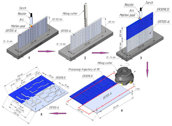
Figure 4.
The scheme of tensile samples’ 3D printing by WAAM using the first strategy: 1—printing ER70S-6; 2—milling; 3—printing ER309LSI; 4—milling; 5—waterjet cutting.
The second WAAM 3D printing strategy (Figure 5) differs basically in that surfacing with ER309LSI welding wire was carried out on the side surface of a pre-machined ER70S-6 wall. In this case, the deposited layers of ER70S-6 and ER309LSI steels were located at an angle of 90° relative to each other. Then, the final machining of the workpiece and its contour waterjet cutting were performed. Using this strategy, sample 5 (Figure 5) was obtained with a boundary between two materials along the thickness of the sample.
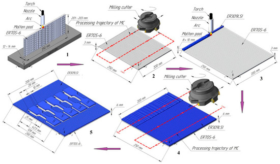
Figure 5.
The scheme of tensile samples’ 3D printing using the second strategy: 1—printing ER70S-6; 2—milling; 3—printing ER309LSI; 4—milling; 5—waterjet cutting.
During the manufacture of samples for mechanical testing, the balance of 50/50 alloys was maintained. This value was achieved by controlling the average layer thickness and performing additional machining.
Tensile tests were carried out on a Tinius Olsen 600SL tensile testing machine (Tinius Olsen, Redhill, UK) at a loading rate of 5 mm/min and a temperature of 20 °C.
2.6. Heat Treatment Modes
Some of the samples obtained by different surfacing strategies were subjected to additional heat treatment in an EKPS-10 electric muffle furnace of the SNOL type (Novosibirsk, Russia). The following heat treatment modes were chosen for further research of the material’s structure and mechanical properties:
- Austenization—heating the sample to a temperature of 1100 °C, holding at this temperature for 1 h, and subsequent cooling in water.
- Austenization + Normalization (normalization annealing): heating the sample to a temperature of 930 °C, holding at this temperature for 1 h, and then cooling in still air.
3. Results and Discussion
3.1. Geometry
One of the most significant criteria for the successful implementation of additive manufacturing of materials and structures (including the WAAM method) is a high level of material utilization. Considering the WAAM method, the factor largely determines the geometry parameters and surface contour of the printed samples, particularly the percentage of the wire amount used in the printing process going into chips when implementing a hybrid technology (WAAM + end mill finish machining).
The geometry parameters of the workpiece after WAAM depend on the technological modes of printing that are set by the option of transferring the surfacing material to the weld pool (short circuit or pulse, in which controlled droplet transfer of the material is performed), as well as the temperature of the thermal interlayer cycle (Tc) and the composition of the protective atmosphere. Figure 6 shows a general view of the vertical walls made of ER 70S-6 and ER 309LSi steels, while for the ER70S-6 wire, the pulsed mode was applied, and for the ER309LSI wire, various WAAM technological modes were applied.
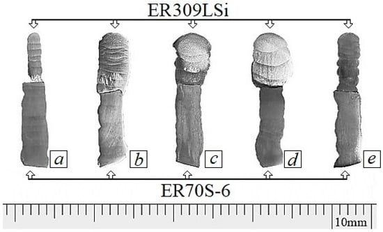
Figure 6.
The geometry of the samples obtained by the WAAM method: (a,b)—short circuit mode with Q = 0.5 kJ/mm (a) and Q = 0.86 kJ/mm (b) and thermal cycle temperature (Tc) of 80 °C; (c–e)—pulse drip mode (Q = 0.6 kJ/mm) with Tc = 350 °C (c), 750 °C (d), and 80 °C (e) (Table 3).
Figure 6 shows the shaping of a layered bimetallic workpiece at various specific energies (heat input) (Figure 6a,b), various interlayer thermal cycles Tc (Figure 6c–e), as well as at various modes of the surfacing material’s transfer into the weld pool (Figure 6b,e).
The formation of a wall in a short circuit mode Q = 0.5 kJ/mm (Figure 6a) accelerates the cooling process and reduces heat input into the previous layers, which leads to the production of a workpiece with a sufficiently smooth surface contour. However, the desired thickness of the workpiece was not achieved, and the accelerated heat removal of the first layer led to rapid solidification and an additional reduction in the residence time in the liquid phase, which further reduced the thickness of the obtained workpiece. Increasing the input energy to Q = 0.86 kJ/mm (Figure 6b) causes an increase in the consumption of surfacing material, an increase in the residence time of ER309LSi steel in the liquid state, and a workpiece thickness exceeding the thickness of the less expensive ER70S-6 welding wire workpiece. It should be noted that at this energy value, the edge deposition of subsequent layers on previous layers and the formation of a large amount of embrittling intermetallic chromium phases are possible.
Comparing the modes with different thermal cycle temperatures (Tc) (Figure 6c–e), it can be said that the best sample geometry parameters were obtained only in the mode with complete cooling of the deposited layer to 80 °C. At Tc = 350 °C (Figure 6d), as the number of layers increases, the thickness of the sample increases, and in the case of Tc = 750 °C (Figure 6e), the thickness decreases as the number of deposited layers increases. This is due to the long stay of the molten alloy in the liquid phase, the transfer of a large amount of heat to the lower layer, and its spreading. A similar effect is discussed in the article [70] and is associated with a change in the viscosity of the metal due to the accumulated temperature in the upper layers.
Thus, in order to obtain samples with the most correct geometric shape, it is recommended to use the "Double Pulse" mode with the layer cooling down to 80 °C.
3.2. Alloying Element Analysis
A spectral analysis of the fabricated vertical walls’ central zones and areas adjacent to the fusion zone of ER70S-6 and ER309LSI steels (Figure 3) was carried out. The obtained distribution of the researched bimetals’ main alloying elements depending on the WAAM modes and the subsequent heat treatment is presented in Table 4.
Table 4.
The results of analysis of the alloying elements’ content in samples obtained at various WAAM parameters.
Assessing the effect of the surfacing process’ Q (modes A, B) specific energy on the alloying composition of the ER70S-6 and ER309LSI composites, the fact of a significant decrease in the concentration of silicon and manganese in the near-boundary and central zones with an increase in the energy spent on surfacing should be noted. The content of chromium and nickel in the border areas of ER309LSI steel remains at the same level. However, the mass fraction of carbon in the near-boundary zone of the sample obtained by mode B is slightly reduced.
Comparing the chemical composition of the samples’ studied zones (Figure 3), obtained at comparable levels of the specific energy of surfacing and interlayer thermal cycles but different in the type of transfer of the deposited material into the weld pool (A and E), it can be stated that, in contrast to the transfer of substance by a short circuit, during pulsed droplet transfer of material, no changes in the content of silicon and manganese are observed, and the distribution of carbon in the near-boundary and researched central zones remains uniform. However, when analyzing the sample obtained according to mode E, the fact of a decrease in the concentration of chromium and nickel in the border zone was established, while the iron content was increased.
During an analysis of the results stated in Table 4, the effect of interlayer soaking temperatures (Tc) on the distribution of the chemical composition in the central and near-boundary zones (WAAM C, D, and E modes) was established. It was observed that an increase in the interlayer holding temperature leads to an increase in the gradient of the mass fraction of silicon and manganese between the central and near-boundary zones of ER309LSI steel. The distribution of chromium and nickel content in samples E and D is different. When implementing the mode with Tc = 750 °C, the distribution of chromium and nickel between the central and near-boundary zones of ER309LSI steel (zones 1 and 2 in Figure 3) remains uniform, and the mass fraction of carbon in the near-boundary area is reduced. Mode E with Tc = 80 °C is characterized by a decrease in the content of chromium (by 2%) and nickel (by 1%) in the border zone, while the carbon content in zones 1 and 2 remains equivalent.
An analysis of heat treatment’s effect after 3D printing according to mode E (Table 3) shows that the austenitization operation followed by normalization annealing leads to a slight decrease in the mass fraction of carbon at the composite boundary (zone 2), and the austenitization process is accompanied by a decrease in the chromium content (by 1.5%) and nickel (by 1%) in the border area. Such an effect for heat treatment in the form of austenization and normalization annealing was not found.
The conducted studies illustrate that the distribution of chemical elements in different parts of the ER70S-6 steel included in the bimetallic composite is stable or does not depend on the WAAM parameters for ER309LSI steel and the type of further heat treatment. For steel ER309LSI, the distribution of chemical elements significantly depends on the WAAM mode and the type of heat treatment. The most uniform chemical composition is exhibited by samples obtained according to mode E (Table 3), as well as samples after heat treatment by way of austenitization and subsequent normalization annealing.
3.3. Microstructure
The study of the layered bimetallic composite samples’ microstructures made of ER70S-6 and ER309LSI steels after WAAM-printing and the subsequent heat treatment (austenization, austenization + normalization annealing) was carried out according to the scheme in Figure 3.
For chromium-nickel steels with a high content of chromium and nickel, the formation of phase composition is related to the Creq/Nieq ratio and is shown in Figure 7 [71]. To calculate Creq and Nieq, the following formulas are used:
Creq = wt.%Cr + wt.%Mo + 1.5wt.%Si + 0.5wt.%Nb
Nieq = wt.%Ni + 0.5wt.%Mn + 30wt.%C + 30wt.%N
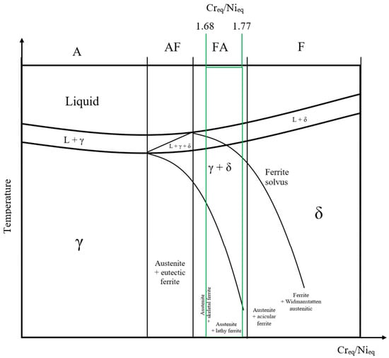
Figure 7.
Ratio of the solidification type and the pseudo-binary phase diagram for austenitic stainless steel.
Calculated Creq/Nieq ratios for different zones of the bimetallic samples printed in different modes and after thermal treatment are presented in Table 4. The values of Creq/Nieq for ER309LSI steel after WAAM range from 1.68 to 1.77, while the researched material should be related to the ferritic–austenitic structural zone (Figure 7). According to the diagram in Figure 7, the formation of phase composition proceeds according to the following scheme:
Based on the foregoing, when cooling steel ER309LSI after deposition of a layer, the formation of austenite + skeletal and lathy ferrite phases should be expected, and also, according to the Scheffler diagram, intermetallic chromium phases (σ-phase) should be formed, which decompose into two Cr-rich and Cr-low solid solutions [32] at the state of cooling. It should be noted that the formation of the Ϭ-phase takes place in the temperature range of 500–900 °C; therefore, staying in the mentioned range of temperatures should increase the amount of intermetallic chromium phases after complete cooling.
The obtained microstructures of the researched bimetallic samples, fabricated by modes with different specific energies and different types of transfer of the deposited material into the weld pool (A, B, and E), are shown in Figure 8. The microstructures of the samples produced by different modes of interlayer thermal exposure (C, D) are shown in Figure 9. The microstructures of the samples manufactured by mode E (Table 3) followed by heat treatment (austenization, austenization + normalization annealing) are shown in Figure 10.
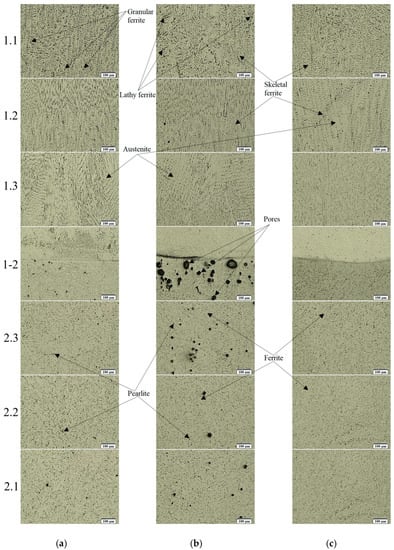
Figure 8.
Microstructures of the bimetallic composite samples’ from ER70S-6-ER309LSI, obtained by different modes of WAAM: (a)—mode A (Table 3); (b)—mode B; (c)—mode E.
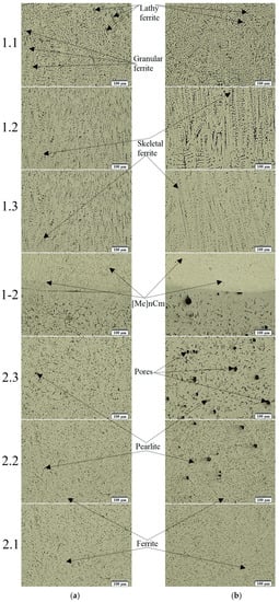
Figure 9.
Microstructures of the bimetallic composite samples’ from ER70S-6-ER309LSI, obtained by different modes of WAAM: (a)—mode C (Table 3); (b)—mode D.
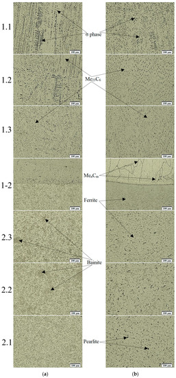
Figure 10.
Microstructures of the bimetallic composite samples’ from ER70S-6-ER309LSI, obtained by E mode followed by heat treatment: (a)—austenization; (b)—austenization + normalization annealing.
The formation of each zone of the bimetallic composite material’s structure in the WAAM process is determined by its chemical composition, the process of melt solidification, and the time of the subsequent stay of the layer in the temperature range of annealing and resolidification.
The phase components of the ER309LSI steel structure are determined by the scheme (3), and the amount of δ-ferrite formed during solidification is determined by the Creq/Nieq ratio. An increase in this ratio leads to an increase in the amount of δ-ferrite, and vice versa, a decrease in the Creq/Nieq ratio increases the amount of austenite in the structure.
Table 4 shows the Creq/Nieq values for the researched zones of ER309LSI steel and ranges from 1.68 to 1.77, which indicates a significant presence of the δ-ferrite phase in the alloy structure. According to the Scheffler diagram, the presence of δ-ferrite in the structure of a material containing 22–24% chromium and 11–13% nickel can reach 10%.
An analysis of the obtained samples’ microstructures, stated in Figure 8, Figure 9, and Figure 10, with different specific energy expended during surfacing, different types of transfer of the surfacing material into the weld pool, and different interlayer thermal exposure shows that, depending on the WAAM mode, the equidistant from the boundary zones of materials made of ER309LSI steels have a different ratio of austenite and δ-ferrite, which, in turn, has a different morphological structure (lathy ferrite, granular ferrite, and skeletal ferrite) and intermetallic phase ratio.
The samples obtained by the WAAM modes A and B (Figure 8a,b) have a similar structure during solidification. The microstructure of steel ER309LSI, which is part of the bimetallic composite, is represented by austenite and δ-ferrite of various morphological structures; carbides and σ-phase (chromium intermetallic compounds) are also present. The weld layers of ER309LSI steel contain lathy ferrite, granular ferrite, and skeletal ferrite.
The structure of samples’ zone 1.1 (Figure 3) obtained by the WAAM modes A–D contains three morphological types of δ-ferrite. It should be noted that the structure of the transition zone of samples A and B (Figure 8) is represented by distinctive zones of austenite grains formed in the direction of heat removal.
As for the samples obtained according to the WAAM E mode (Figure 8), their structure in the researched zones 1.1, 1.2, and 1.3 is similar to the structures obtained on the samples according to the C and D modes (Figure 9). The structure of ER309LSI steel, as mentioned above, consists of austenite and δ-ferrite phases of various morphologies with dispersed inclusions of carbides (Me23C6) and a σ-phase located along the austenitic-ferrite boundary zones [32].
In the structure of the samples made of ER309LSI steel, obtained according to mode E with the subsequent heat treatment (Figure 10a,b), the crushing of dendritic structural components and a decrease in the amount of the δ-ferrite phase are observed. The structure of the boundary zone (1.3) is represented by an austenitic phase with dispersed inclusions of the σ-phase and carbides (Me23C6) of various morphology and composition.
The transition zones (1-2, Figure 3) of the studied bimetallic composite materials are of particular interest, as the structural components and internal stress fields formed at the boundary between two materials mainly determine the mechanical characteristics of layered composites. The structure of the boundary zones (1-2) of ER309LSI steel is a zone of reduced etchability that is related to the formation of Cr-rich and Cr-low zones with accelerated heat removal during the formation of the first deposited layer. It should be noted that during the implementation of the WAAM E mode with droplet transfer of material and interlayer temperature exposure of 80 °C, Cr-rich zones are formed at the boundary between two materials (1-2), represented by near-boundary light areas in Figure 8c.
The influence of a long stay in the boundary zone of ER309LSI steel (modes C, D, and E followed by austenitization and normalization annealing) contributes to the growth of austenite grains and the migration of [Me]23C6 carbides to grain boundaries.
The structure of steel ER70S-6, formed in various WAAM modes, is represented by ferrite and a ferrite–cementite mixture (pearlite). During heat treatment by way of austenitization, the structure of ER70S-6 steel is represented by ferrite and bainite areas. It is noted that in all samples in the boundary zones (1-2) of ER70S-6 steel, the presence of a decarburized layer is observed that is characterized by reduced hardness and can reach about 100 μm when the mode is implemented with an interlayer holding temperature Tc = 750 °C. Additionally, a long stay at a temperature above the resolidification temperature leads to a noticeable growth of the ferrite grain. The modes with increased values of specific deposition energy and temperature of interlaminar exposure contribute to the formation of pores located along the vertical axis of the sample from the steel ER70S-6 (Figure 8b and Figure 9b). These modes are distinguished by an increased temperature of the weld pool during the implementation of WAAM with the transfer of the deposited material by means of a short circuit and the mode with Tc = 750 °C, while the residence time of the deposited metal in the liquid phase is increased. The highest concentration and size of pores are observed in the border areas 1-2 (Figure 3) on the side of steel ER70S-6. The pores are spherical and vary in diameter. So, in steel ER70S-6 of a bimetallic sample made according to mode A, the formed pores have a diameter that does not exceed 15 µm, and in a sample obtained according to mode B, the formed pores have a diameter that can reach 70 µm. In the sample produced according to mode D, the pore diameter has a range of 30–50 µm.
Most likely, during the implementation of WAAM modes A, B, and D (Table 3), the formation of keyhole-type pores occurs [72]. This type of pore appears when the temperature of the weld pool is high enough to cause metal evaporation, and further voids form at the root of the weld pool that are filled with process gas. Due to the high thermal conductivity of ER70S-6 steel, there is not enough time to complete the degassing of the weld pool during melt crystallization. This leads to the blocking of process gases in the material and the formation of keyhole pores.
Summing up the study of the microstructure of the obtained bimetallic composite ER70S-6-ER309LSI, in order to obtain high values of the mechanical properties of the composite, the E printing mode should be used, followed by heat treatment by way of austenization and normalization annealing, which provides fragmentation of the dendritic component of the structure and a decrease of the amount of the δ-ferrite phase.
3.4. Ferrite Phase Analysis
An analysis of the magnetic (δ-ferrite) phase’s content in the produced samples was carried out in various technological modes of WAAM (Figure 6). The measurement was taken along the vertical axis of the samples in the center with a step of ~2 mm. The results are shown in Figure 11.
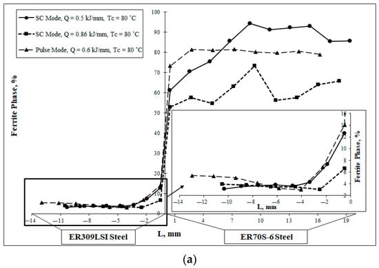
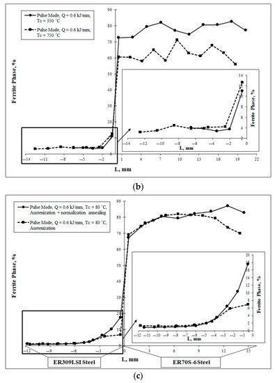
Figure 11.
The distribution of the ferrite phase in layered bimetallic composite samples (WAAM) depending on: (a)—specific energy and method of substance transfer into the weld pool; (b)—interlayer thermal cycle mode; (c)—heat treatment mode after WAAM.
Comparing the δ-ferrite phase’s content in the samples obtained by the WAAM method in modes A and B (Table 3), it was found that the resulting amount of the δ-ferrite phase is ~3%. At the same time, the content of the ferrite phase in the border zones is different. For the mode with Q = 0.5 kJ/mm, the content of magnetic δ-ferrite phase is much higher and reaches ~13% (for the characteristic zone obtained according to the mode Q = 0.86 kJ/mm, ~7%), which is consistent with the structures of the near-boundary zones in Figure 8a,b. Mode E is characterized by an increased content of the δ-ferrite phase in the near-boundary zone and in the zone of the extreme (upper) deposited layer. Both areas considered are characterized by high cooling rates during solidification. Thus, with an increase in the velocity of steels ER309LSI solidification after melting, an increase in the residual magnetic δ-ferrite phase occurs.
Assessing the effect of interlayer thermal exposure’s temperature during the implementation of modes C and D (Table 3), it should be noted that the average content of the δ-ferrite phase in steel ER309LSI increased to ~4%. At the same time, the border zone with a high content of the δ-ferrite phase was reduced to 2 mm (in the case of Tc = 80 °C with a similar pulse mode E, this zone is ~4 mm). From the values obtained in Figure 11b, it follows that an increase in the interlayer exposure temperature leads to an increase in the near-boundary content of the δ-ferrite phase in the ER309LSI steel, which is part of the layered bimetallic composite.
Applying heat treatment in the form of austenization and austenization followed by normalization of the ER70S-6—ER309LSI composite (Figure 11c), it was possible to reduce the average content of the δ-ferrite phase in ER309LSI steel to 1.5%. However, a long stay of the composite at temperatures above 900 °C (during the implementation of heat treatment by way of austenitization and subsequent normalization) leads to a significant increase in the content of the δ-ferrite phase in the near-boundary zone of ER309LSI steel.
Summarizing the obtained results of the study, it can be concluded that the use of heat treatment after WAAM by way of austenitization and subsequent normalization leads to a significant decrease in the average content of the δ-ferrite phase in the ER309LSI steel of the researched composite. However, when performing normalization annealing, it is necessary to reduce the residence time of the bimetallic composite at temperatures above 900 °C, which reduces the content of the δ-ferrite phase in the near-boundary zone.
It is possible to distinguish the different nature of δ-ferrite depending on when it was formed, how much it managed to dissolve when interacting with liquid steel during the peritectic reaction, as well as when the temperature of solid steel decreases below the solidus temperature or after austenitization. For chromium-nickel steels of the ferritic-austenitic class with Creq/Nieq = 1.48–1.95, several important temperature ranges can be picked out, limited by the corresponding critical points:
- -
- A range of 1400–1325 °C, in which the δ-ferrite formed during crystallization interacts with liquid steel with the formation of austenite by the peritectic reaction.
- -
- A range of 1325–1075 °C, in which δ-ferrite dissolves in austenite when the temperature of solid steel drops below the solidus temperature. With rapid cooling of solid steel, kinetic limitations of dissolution are possible.
- -
- A range of 1075–925 °C, in which, with sufficient exposure time, δ-ferrite, which remained after crystallization and solidification and did not have time to dissolve when solid steel is cooled in the temperature range of 1325–1075 °C, should completely dissolve in austenite.
The austenitization temperature for steel of this chemical composition is selected in the range of 1075–925 °C and should be high enough to ensure the diffusion mobility of alloying elements in the steel but not so high as to reach the temperature of the onset of δ-ferrite formation.
- -
- Below 925 °C, ferrite precipitates from austenite, which participates in the eutectoid reaction of the formation of the σ-phase; however, the development of this process is kinetically retarded and can be ignored.
An increase in the nickel concentration in steel with a simultaneous decrease in the chromium concentration naturally leads to a decrease in the amount of δ-ferrite formed in the temperature range 1400–1325 °C, an expansion of the temperature range 1075–925 °C, and a narrowing of the interval 1325–1075 °C.
The ratio of austenitic and δ-ferritic phases affects the mechanical properties of ER309LSI steel made by the WAAM method. An increase in the volume content of ferrite leads to hardening and a decrease in the plasticity and corrosion resistance of steels [25].
3.5. X-ray Diffraction
The X-ray patterns obtained during the study of the layered bimetallic composite’s ER70S-6-ER309LSI researched zones (Figure 3) are presented in Figure 12.
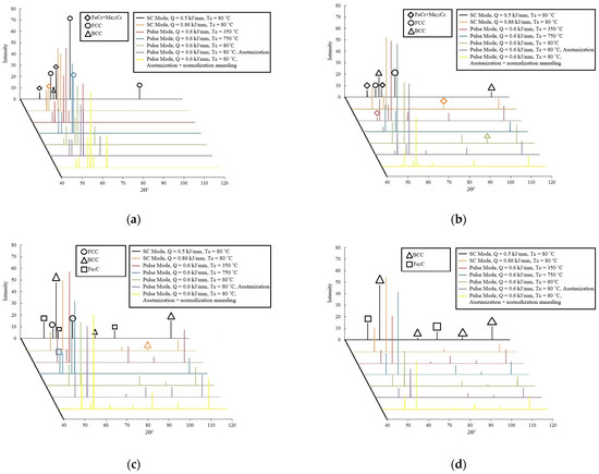
Figure 12.
The X-ray patterns of the layered bimetallic composite’s ER70S-6—ER309LSI researched zones (Figure 3): (a)—zone 1; (b)—zone 2; (c)—zone 3; (d)—zone 4.
Zones 1 and 2 (ER309LSI steel, Figure 3), in accordance with Creq/Nieq~1.70 (Table 4), are represented by a ferrite–austenitic structure (Figure 8, Figure 9 and Figure 10) that is shown in Figure 12a,b as a significant intensity of FCC (γ) and BCC (α-Fe, Cr) crystal lattices. Moreover, on the X-ray patterns of the studied zones 1 and 2, lines characteristic of chromium intermetallic compounds and chromium carbides of the Me23C6 type were found.
The structures of the studied zones 3 and 4 (steel ER70S-6, Figure 3) are represented by ferrite and ferrite–carbide (pearlite) mixtures (Figure 8, Figure 9 and Figure 10). On the obtained X-ray diffraction patterns of the considered zones (Figure 12c,d), there are lines characteristic of ferrite (α-Fe, BCC) and cementite (Fe3C), which correspond to the resulting structures of ER70S-6 steel. However, on the X-ray diffraction pattern of zone 3 (Figure 12c) of the sample obtained by the WAAM D mode (Table 3), lines characteristic of FCC were found, which indicate partial mixing of materials in the border zone due to the high temperature of the interlayer exposure (an increase in the values of diffusion coefficients) and a long-stay deposited layer in the liquid phase.
Based on the obtained X-ray diffraction patterns, phase analysis of the samples’ studied zones obtained in various technological modes of WAAM was carried out. The results of the phase distribution in the resulting bimetallic composite are presented in Figure 13, Figure 14 and Figure 15.
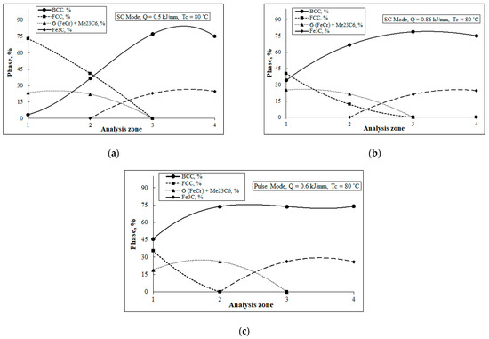
Figure 13.
The distribution of phase composition in layered bimetallic composite samples (WAAM) depending on the specific energy and method of transferring the substance to the weld pool: (a)—sample A (Table 3); (b)—sample B; (c)—sample E.
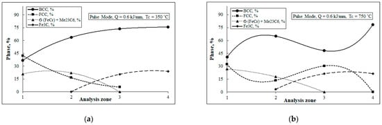
Figure 14.
The distribution of phase composition in layered bimetallic composite samples (WAAM) depending on the specific energy and method of transferring the substance to the weld pool: (a)—sample C (Table 3); (b)—sample D.
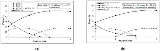
Figure 15.
The distribution of phase composition in layered bimetallic composite samples (WAAM) depending on the specific energy and the method of transferring the substance to the weld pool: (a)—sample E, austenization; (b)—sample E, austenization + normalization annealing.
A phase analysis of the central and boundary zones of composite samples’s ER309LSI steel, the WAAM modes of which are different in terms of the specific deposition energy, allows us to state that the implementation of mode A with Q = 0.5 kJ/mm (Figure 13a) contributes to an increase in the amount of the crystal lattice’s FCC in the central and boundary zones, which is consistent with microstructural studies (Figure 8a,b), wherein the distribution of phases in the researched zones of FeCr and Me23C6 has a similar nature.
It should be noted that the amount of BCC (Fe and Cr) component during the printing in modes A and B increases in the border area. A feature of the phase distribution in the sample, obtained by the pulse mode E, is the complete absence of the FCC (γ) component in the near-boundary zone, while the proportion of BCC phases is significant. These results are consistent with the results of structural studies (Figure 8c) and the content of δ-ferrite phase in Figure 11a.
The feature of the distribution of the samples’ phase composition, obtained according to mode D with an interlayer exposure temperature Tc = 750 °C (Figure 14b), is an increased content of FCC (γ) in the border zone (3, Figure 3), while the amount of the BCC component is reduced.
This may indicate partial boundary mixing of the structural components of the ER309LSI and ER70S-6 steels in the composite during a long stay of the materials in the liquid phase. During the implementation of the mode with Tc = 750 °C, an increase in the content of FeCr and Me23C6 components in the central zone (zone 1 in Figure 3) of ER309LSI steel is also observed.
An analysis of the phase distribution in the samples, obtained according to mode E with further heat treatment (Figure 15), shows that heat treatment in the form of austenitization increased the content of FCC (γ) in the central and border zones (zones 1 and 2 in Figure 3), while the BCC ratio is significantly reduced. When implementing heat treatment in the form of austenization followed by normalization annealing, a decrease in the BCC component is also observed in all researched zones of ER309LSI steel, as well as an increase in the FCC (γ) component in the near-boundary zone.
Thus, using heat treatment of bimetallic composites obtained by the WAAM method, it is possible to significantly change the phase composition of the ER309LSI steel included in the composite, reducing the level of BCC structural components and near-boundary Cr-rich intermetallic components.
3.6. Microhardness
According to the scheme stated in Figure 3, the microhardness measurements were carried out for bimetallic composite samples from ER70S-6-ER309LSI steel, obtained in various WAAM modes (Figure 6). The results of the distribution of microhardness along the vertical axis of the workpiece are shown in Figure 16.
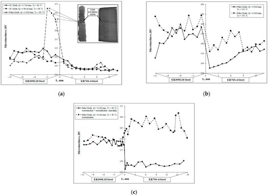
Figure 16.
The distribution of microhardness in the bimetallic composite ER70S-6—ER309LSI (WAAM) depending on: (a)—specific energy and method of substance transfer into the weld pool; (b)—interlayer thermal cycle mode; (c)—heat treatment mode after WAAM.
Analyzing the microhardness’ distribution of the samples shown in Figure 16a, the high similarity of the graph correlation of the samples produced in the short circuit mode but with different specific deposition energies (Q = 0.5 and Q = 0.86) should be noted. At the same time, the dependences obtained in the short circuit mode do not have sharp boundary gradients of microhardness values. However, the overall near-boundary zone microhardness’ level of the sample obtained by the mode with a higher specific energy is reduced. The following effect is associated with a large heat input into the deposited and preceding layers, which leads to an increase in the duration of the layers’ stay in the annealing temperature zone. The distribution of microhardness in the sample obtained by the pulse mode with drop transfer of the surfacing material into the melting zone has a different character. As a result of accelerated heat removal during the formation of the first (lower) layer of ER309LSI steel, a 4 mm zone with significantly higher microhardness values is formed. The stated data are consistent with the results of structural (Figure 8c) and X-ray diffraction (Figure 13c) studies, indicating the formation of a Cr-rich border zone on the sample obtained by mode E.
The thermal treatment in the form of austenization and subsequent normalization annealing of the bimetallic composite produced by the WAAM method in mode E (Table 3) made it possible to obtain a uniform distribution of microhardness along the vertical axis of the sample in each material used in the manufacture of the ER70S-6—ER309LSI composite. In the case of applying only the operation of austenization to a sample obtained by the same mode E, the distribution of microhardness becomes uneven, while the values of microhardness are jumpy.
Summing up the analysis of the microhardness of the composite ER70S-6—ER309LSI, a significant positive effect of the heat treatment in the form of austenitization followed by normalization annealing should be noted. Such processing made it possible to significantly increase the stability of microhardness values along the vertical axis for each material included in the composite. However, the workpieces obtained by the WAAM A and B modes also have sufficient stability for the obtained microhardness values (Table 3). In our opinion, such an effect occurs during the deposition of subsequent layers according to the mode of transfer of the surfacing material by means of a short circuit, which leads to cyclic heating of the underlying layers of the workpiece to the annealing temperature range.
3.7. Mechanical Properties
As a result of mechanical tensile tests of flat samples (Figure 4 and Figure 5) cut from the initial WAAM samples (mode E in Table 3) made of steels ER70S-6 and ER309LSI, as well as from a layered bimetallic composite ER70S-6-ER309LSI, the tension diagrams (Figure 17, Figure 18, Figure 19, Figure 20 and Figure 21) were obtained, and the main mechanical characteristics of the bimetallic composite and its constituent materials were determined (Table 5). To study the effect of heat treatment on the mechanical properties and nature of fracture during uniaxial tension of the layered composite, as well as the materials forming it, some of the samples obtained according to the schemes in Figure 4 and Figure 5 were exposed to heat treatment by way of austenization and austenization followed by normalization annealing. To clarify the statistical indicators, a total of five experimental samples of each type with different types of heat treatments were studied.
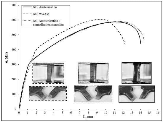
Figure 17.
Tensile diagrams of samples No. 3 made of steel ER309LSI obtained by the WAAM.
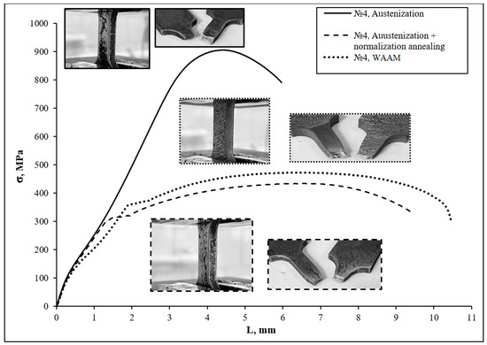
Figure 18.
Tensile diagrams of samples No. 4 made of steel ER70S-6 obtained by WAAM technology.
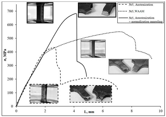
Figure 19.
Tensile diagrams of bimetallic samples No. 5 obtained by the WAAM method.
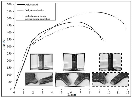
Figure 20.
Tensile diagrams of bimetallic samples No. 1 obtained by the WAAM method.
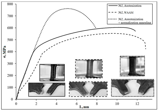
Figure 21.
Tensile diagrams of bimetallic samples No. 2 obtained by the WAAM method.
Table 5.
Mechanical properties of the ER70S-6—ER309LSI bimetallic composite and its constituent materials obtained by the WAAM method.
The results of uniaxial tensile tests of samples made of ER309LSI steel (Figure 17) obtained by the WAAM method according to the E mode (Table 3) and samples with subsequent heat treatment showed that the samples after WAAM had increased fluidity strength and tensile strength while maintaining high plasticity. Heat treatment by way of austenization contributes to a significant (up to 25%) decrease in yield strength and increases the relative extension from 37.4% to 43.6%. Heat treatment, consisting of austenization followed by normalization, contributes to a further increase in the plasticity of the samples while maintaining the values of strength characteristics at the level of the samples after austenitization. Based on the obtained results, it can be concluded that the structure of ER309LSI steel formed during WAAM (E mode) provides an optimal ratio of strength and plasticity; however, the fatigue strength and impact toughness characteristics of such samples will be reduced.
The tensile diagrams and fracture morphology of ER70S-6 steel samples are shown in Figure 18. The samples after WAAM according to mode E (Table 3) have an optimal combination of strength and plasticity (the relative extension of the sample is 34%). Heat treatment by way of austenization (in fact, the process of hardening) contributes to an increase in the yield strength and strength up to 2.5 times; however, the formation of a bainitic structure (Figure 10a) in the steel under consideration contributes to a significant decrease in plasticity (the relative extension of the sample is 13.7%), which limits the use of ER70S-6 steel as a component of a layered bimetallic composite. Heat treatment by way of austenitization followed by normalization led to a decrease in yield strength of 16%, while the values of plasticity characteristics are comparable to the sample after WAAM without heat treatment. During heat treatment of ER70S-6 steel, phase transformations occur. Thus, heat treatment of a bimetallic composite in the form of ER70S-6 steel’s austenization results in partial hardening, and as a result, the structure of ER70-S6 steel is transformed from ferrite–pearlitic (after WAAM) to ferrite–bainitic. It is known that the presence of a bainite component in the structure contributes to a significant increase in fluidity and strength, while the plasticity of the steel decreases. The subsequent operation of ER70-S6 steel’s normalization annealing leads to diffusion decomposition of the bainite component and the formation of a ferrite–pearlite structure. However, long-term high-temperature exposures (over 900 °C) accelerate the processes of collective recrystallization, while an increase in the average diameter of ferrite grains from 15–20 µm (after WAAM according to mode E) to 50–55 µm is observed. Such an increase in grain size leads to a decrease in the strength and plastic characteristics of ER70S-6 steel.
Tests of samples No. 5 (Figure 5), obtained by surfacing misoriented at an angle of 90° layers made of steel ER70S-6 and ER309LSI, showed a reduced level of plasticity and toughness characteristics (Figure 19). It has been found that with this strategy of building a composite, uniaxial tensile fracture always starts on the side of ER70S-6 steel, since the plasticity of this steel after WAAM is lower. A significant contribution to the reduction in the plasticity of steel ER70S-6 during implementation of the above strategy for constructing a composite is made by residual stresses at the boundary as well as the anisotropy of material properties, depending on the direction of the formed layers. The highest plasticity (relative extension of the sample is 29.5%) among the samples obtained by the considered strategy of constructing the composite is shown by the samples after WAAM without the subsequent heat treatment. Heat treatment most likely contributes to the emergence of a high level of internal stress at the boundary between two materials.
The conducted experiment of bimetallic samples No. 1 (Figure 5) with a perpendicular boundary between two materials in the tested part of the sample showed that the samples after WAAM had the maximum value of yield strength and the minimum value of relative extension 28.2%. Heat treatment by way of austenitization made it possible to significantly increase the tensile strength and plasticity characteristics (relative to sample elongation, 36.7%). At the same time, the values of yield strength are slightly reduced. Heat treatment by way of austenization and subsequent normalization annealing contributed to a decrease in strength properties, while a significant increase in plasticity was not found (Figure 19).
It should be noted that during the implementation of the following strategy, the sample obtained by the WAAM method without subsequent heat treatment has tear zones that are not typical for other samples (Figure 22). So, the first tear is observed on the section of steel ER70S-6 in the capture zone. The second tear is localized at the boundary between the two materials. However, despite the resulting tears, the sample did not collapse and continued to deform. A similar tear at the boundary between two materials was observed during deformation of sample No. 1 after heat treatment by way of austenization and subsequent normalization.
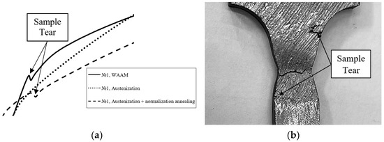
Figure 22.
The “step” in the tensile diagram (a) and the corresponding tears of sample No. 1 after WAAM (b).
The tensile diagrams of bimetallic sample No. 2, in which the boundary between the two materials was located along the tested part of the sample, are shown in Figure 21. The layered bimetallic composite ER70S-6—ER309LSI, obtained using the stated above construction strategy and the WAAM E mode (Table 3), has high values of plasticity (relative extension of the sample 40%), yield strength 380 MPa, and tensile strength 553 MPa. The tension diagram does not contain steps, which indicates uniform joint flow of the materials being a part of the composite during deformation and the absence of tears. Heat treatment of the bimetal by way of austenitization contributed to an increase in the tensile strength of the composite by 9%, while the level of yield strength remains practically unchanged and the plasticity decreases slightly. Heat treatment by way of austenization followed by normalization annealing leads to a significant increase in all strength characteristics. The values of strength increased by 39% and tensile strength by 28%, while the plasticity of the layered bimetallic composite was reduced (the relative extension of the sample was 22.8%).
It should be noted that there are non-linear sections of elastic zones in Figure 18 and Figure 21. We suppose that the irregularity of the samples’ elastic zone after WAAM is primarily associated with the presence of micropores in the ER70S-6 steel and the thermo-structural stresses that arise in materials obtained by the WAAM method due to the irregularity of crystallization and further cooling. It is known that the areas adjacent to the pores are characterized by a high level of compressive stress. Deformation of samples containing micropores leads to their collapse as the degree of deformation increases, the cross section of the working zone changes, and the processes of microfluidity of the material take place. The results of testing samples after heat treatment show that heat treatment in the form of austenization and austenization with normalization makes it possible to eliminate the effect of nonlinearity in the elastic area of tension diagrams (Figure 18 and Figure 22) that is associated with structural recrystallization, leading to annihilations of micropores and redistribution of field internal stresses in the sample.
Thus, the mechanical properties of the bimetallic composite ER70S-6-ER309LSI significantly depend on the strategy of construction during surfacing and the modes of subsequent heat treatment. The values of the strength properties of the composite after WAAM without subsequent heat treatment are formed in the zone of average values of the used materials’ strength characteristics. It should be noted that the construction strategy, in which the boundary between the two materials was located along the test part of the sample, showed the highest values of strength and plasticity characteristics. By applying heat treatment by way of austenitization followed by normalization annealing, it is possible to significantly (up to 30–40%) increase the strength characteristics of the composite while the plasticity characteristics remain at a sufficiently high level from an operational point of view. Other strategies for constructing a composite considered in this study can be limitedly applied, and the approaches to the heat treatment of such workpieces require further study.
4. Conclusions
- In the production of the layered bimetallic composite material “ER70S-6-ER309LSI” by the WAAM method, the synergistic approach to setting the operating mode of the equipment is preferable. It has been established that the WAAM parameters, consisting of the implementation of the welding mode “Double Pulse”, followed by the cooling of a single printed layer to 80 °C, provide the most uniform workpiece geometry with minimal allowances for subsequent machining.
- The distributions of the chemical elements, obtained in the process of the study, in the central and border areas of the ER70S-6 steel, which is a part of the bimetallic composite, are stable and practically do not depend on the WAAM parameters or the type of subsequent heat treatment. For ER309LSI steel, the distribution of the chemical elements in the workpiece is largely determined by the surfacing mode and the type of subsequent heat treatment. Based on the results, it can be argued that the samples produced in welding equipment using the “Double Pulse” operating mode with specific energy consumed during surfacing Q = 0.6 kJ/mm, as well as the samples manufactured using the above WAAM mode with heat treatment in the form of austenitization and subsequent normalization annealing, have the most uniform chemical composition.
- An analysis of the ER70S-6-ER309LSI bimetallic composite’s structure showed that the structure of the ER70S-6 steel, formed in different WAAM modes, is represented by ferrite and a ferrite–cementite mixture (pearlite). It is determined that the structure of steel ER309LSI, depending on the WAAM mode and the zone under consideration, has a different ratio of austenite, δ-ferrite of different morphological structures (lathy ferrite, granular ferrite, skeletal ferrite), carbide, and intermetallic chromium phases. In order to improve the structure of the ER309LSI steel included in the composite, the “Double Pulse” mode should be used with the cooling of a single printed layer to 80 °C and subsequent heat treatment in the form of austenization and normalization annealing of the resulting workpiece. This mode provides grinding of the structure’s dendritic component and reduces the amount of δ-ferrite phase in the structure. However, it should be taken into account that during normalization annealing, the presence of the workpiece at temperatures above 900 °C contributes to an increase in the near-boundary content of δ-ferrite phase, so the exposure time during such heat treatment should be reduced.
- The WAAM mode and the type of subsequent heat treatment have a significant impact on the phase composition of the main layers and the near-boundary zones of the layered bimetallic composite ER70S-6-ER309LSI. Applying heat treatment in the form of austenization and austenization followed by normalization, a decrease in the average content of the δ-ferrite phase in ER309LSI steel to 1.5% is observed. However, as mentioned earlier, in order to reduce the content of the δ-ferrite phase in the near-boundary zone of ER309LSI steel, the sample exposure time during normalization annealing should be reduced.
- An analysis of the microhardness of the bimetallic composite ER70S-6-ER309LSI, obtained using various WAAM and heat treatment modes, showed that heat treatment by way of austenitization followed by normalization annealing has an essential positive effect. Such heat treatment made it possible to significantly increase the stability of microhardness values along the vertical axis for each material included in the composite.
- In the process of the research, it was found that the mechanical properties of the bimetallic composite ER70S-6-ER309LSI depend on the strategy for constructing the composite during the surfacing and modes of subsequent heat treatment, while the values of the strength properties of the composite after WAAM without subsequent heat treatment are formed in the zone of strength characteristics’ averaged values of the materials included in the composite. It should be noted that during the experiment with the ER70S-6-ER309LSI bimetallic composite’s uniaxial tension, the zone of fracture localization was not the boundary between the two materials. Heat treatment by way of austenization followed by normalization annealing made it possible to significantly (up to 30–40%) increase the strength characteristics of the bimetallic composite while maintaining plasticity characteristics at a sufficiently high level from an operational point of view.
- Based on the presented results of the work conducted, it can be concluded that when creating products using the WAAM method from the bimetallic composite “ER70S-6-ER309LSI”, it is necessary to maintain the technological conditions of surfacing to ensure a defect-free structure. At the same time, in the first approximation, the mechanical properties of this system of alloys can be considered a superposition of the properties of the starting materials. To reduce the heterogeneity of the structure, reduce porosity, and improve mechanical properties, it is necessary to carry out additional heat treatment (austenization followed by normalization). As further ways to study this system of alloys, one can note the need for additional mechanical tests (impact strength, fatigue strength, corrosion resistance) in a wide temperature range, as well as the development of additional measures to improve the properties of the transition zone (use of additional filler wires, alloying powders, etc.).
Author Contributions
Conceptualization, D.S. and Y.K.; funding acquisition and investigation, D.S., D.R. and A.S.; writing—original draft, D.S.; writing—review and editing, D.R. and A.S.; methodology, verification, formal analysis, and resources, Y.K. and A.K.; project administration, D.S.; visualization, A.S. All authors have read and agreed to the published version of the manuscript.
Funding
The research was supported by RSF (Project No. 22-79-10204).
Institutional Review Board Statement
Not applicable.
Informed Consent Statement
Not applicable.
Data Availability Statement
Results data can be obtained upon request from the corresponding author.
Conflicts of Interest
The authors declare no conflict of interest.
References
- Herzog, D.; Seyda, V.; Wycisk, E.; Emmelmann, C. Additive manufacturing of metals. Acta Mater. 2016, 117, 371–392. [Google Scholar] [CrossRef]
- Zakay, A.; Aghion, E. Effect of Post-Heat Treatment on the Corrosion Behavior of AlSi10Mg Alloy Produced by Additive Manufacturing. JOM J. Miner. Met. Mater. Soc. 2019, 71, 1150–1157. [Google Scholar] [CrossRef]
- Leon, A.; Shirizly, A.; Aghion, E. Corrosion Behavior of AlSi10Mg Alloy Produced by Additive Manufacturing (AM) vs. Its Counterpart Gravity Cast Alloy. Metals 2016, 6, 148. [Google Scholar] [CrossRef]
- Bai, X.; Colegrove, P.; Ding, J.; Zhou, X.; Diao, C.; Bridgeman, P.; roman Hönnige, J.; Zhang, H.; Williams, S. Numerical analysis of heat transfer and fluid flow in multilayer deposition of PAW-based wire and arc additive manufacturing. Int. J. Heat Mass Transf. 2018, 124, 504–516. [Google Scholar] [CrossRef]
- Wu, B.; Pan, Z.; Ding, D.; Cuiuri, D.; Li, H.; Xu, J.; Norrish, J. A review of the wire arc additive manufacturing of metals: Properties, defects and quality improvement. J. Manuf. Process. 2018, 35, 127–139. [Google Scholar] [CrossRef]
- Ding, D.; Pan, Z.; Cuiuri, D.; Li, H. Wire-feed additive manufacturing of metal components: Technologies, developments and future interests. Int. J. Adv. Manuf. Technol. 2015, 81, 465–481. [Google Scholar] [CrossRef]
- Calleja-Ochoa, A.; Gonzalez-Barrio, H.; López de Lacalle, N.; Martínez, S.; Albizuri, J.; Lamikiz, A. A new approach in the design of microstructured ultrulight components to achieve maximum functional performance. Materials 2021, 14, 1588. [Google Scholar] [CrossRef] [PubMed]
- Li, N.; Huang, S.; Zhang, G.; Qin, R.; Liu, W.; Xiong, H.; Shi, G.; Blackburn, J. Progress in additive manufacturing on new materials: A review. J. Mater. Sci. Technol. 2019, 35, 242–269. [Google Scholar] [CrossRef]
- Bajaj, P.; Hariharan, A.; Kini, A.; Kürnsteiner, P.; Raabe, D.; Jägle, E.A. Steels in additive manufacturing: A review of their microstructure and properties. Mater. Sci. Eng. A 2020, 772, 138633. [Google Scholar] [CrossRef]
- DebRoy, T.; Wei, H.L.; Zuback, J.S.; Mukherjee, T.; Elmer, J.W.; Milewski, J.O.; Beese, A.M.; Wilson-Heid, A.; De, A.; Zhang, W. Additive manufacturing of metallic components–Process, structure and properties. Prog. Mater. Sci. 2018, 92, 112–224. [Google Scholar] [CrossRef]
- Frazier, W.E. Metal additive manufacturing: A review. J. Mater. Eng. Perform. 2014, 23, 1917–1928. [Google Scholar] [CrossRef]
- Yu, H.; Yang, J.; Yin, J.; Wang, Z.; Zeng, X. Comparison on mechanical anisotropies of selective laser melted Ti-6Al-4V alloy and 304 stainless steel. Mater. Sci. Eng. A 2017, 695, 92–100. [Google Scholar] [CrossRef]
- Hou, J.; Chen, W.; Chen, Z.; Zhang, K.; Huang, A. Microstructure, tensile properties and mechanical anisotropy of selective laser melted 304 L stainless steel. J. Mater. Sci. Technol. 2020, 48, 63–71. [Google Scholar] [CrossRef]
- Zhang, Y.; Huang, W. Comparisons of 304 austenitic stainless steel manufactured by laser metal deposition and selective laser melting. J. Manuf. Proc. 2020, 57, 324–333. [Google Scholar] [CrossRef]
- Kurzynowski, T.; Gruber, K.; Stopyra, W.; Kuźnicka, B.; Chlebus, E. Correlation between process parameters, microstructure and properties of 316 L stainless steel processed by selective laser melting. Mater. Sci. Eng. A 2018, 718, 64–73. [Google Scholar] [CrossRef]
- Salman, O.O.; Brenne, F.; Niendorf, T.; Eckert, J.; Prashanth, K.G.; He, T.; Scudino, S. Impact of the scanning strategy on the mechanical behavior of 316L steel synthesized by selective laser melting. J. Manuf. Process. 2019, 45, 255–261. [Google Scholar] [CrossRef]
- Kruth, J.-P.; Levy, G.; Klocke, F.; Childs, T.H.C. Consolidation phenomena in laser and powder-bed based layered manufacturing. CIRP Ann. 2007, 56, 730–759. [Google Scholar] [CrossRef]
- Gordon, J.V.; Haden, C.V.; Nied, H.F.; Vinci, R.P.; Harlow, D.G. Fatigue crack growth anisotropy, texture and residual stress in austenitic steel made by wire and arc additive manufacturing. Mater. Sci. Eng. A 2018, 724, 431–438. [Google Scholar] [CrossRef]
- Le, V.T.; Mai, D.S.; Hoang, Q.H. Effects of cooling conditions on the shape, microstructures, and material properties of SS308L thin walls built by wire arc additive manufacturing. Mater. Lett. 2020, 280, 128580. [Google Scholar] [CrossRef]
- Li, Y.; Luo, Y.; Li, J.; Song, D.; Xu, B.; Chen, X. Ferrite formation and its effect on deformation mechanism of wire arc additive manufactured 308 L stainless steel. J. Nuclear Mater. 2021, 550, 152933. [Google Scholar] [CrossRef]
- Chen, X.; Li, J.; Cheng, X.; He, B.; Wang, H.; Huang, Z. Microstructure and mechanical properties of the austenitic stainless steel 316L fabricated by gas metal arc additive manufacturing. Mater. Sci. Eng. A 2017, 703, 567–577. [Google Scholar] [CrossRef]
- Wang, L.; Xue, J.; Wang, Q. Correlation between arc mode, microstructure, and mechanical properties during wire arc additive manufacturing of 316L stainless steel. Mater. Sci. Eng. A 2019, 751, 183–190. [Google Scholar] [CrossRef]
- Yang, K.; Wang, Q.; Qu, Y.; Jiang, Y.; Bao, Y. Microstructure and corrosion resistance of arc additive manufactured 316L stainless steel. J. Wuhan Univ. Technol. Mater. Sci. Ed. 2020, 35, 930–936. [Google Scholar] [CrossRef]
- Astafurova, E.G.; Panchenko, M.Y.; Moskvina, V.A.; Maier, G.G.; Astafurov, S.V.; Melnikov, E.V.; Fortuna, A.S.; Reunova, K.A.; Rubtsov, V.E.; Kolubaev, E.A. Microstructure and grain growth inhomogeneity in austenitic steel produced by wire-feed electron beam melting: The effect of post-building solid-solution treatment. J. Mater. Sci. 2020, 55, 9211–9224. [Google Scholar] [CrossRef]
- Tarasov, S.Y.; Filippov, A.V.; Savchenko, N.L.; Fortuna, S.V.; Rubtsov, V.E.; Kolubaev, E.A.; Psakhie, S.G. Effect of heat input on phase content, crystalline lattice parameter, and residual strain in wire-feed electron beam additive manufactured 304 stainless steel. Int. J. Adv. Manuf. Technol. 2018, 99, 2353–2363. [Google Scholar] [CrossRef]
- Panchenko, M.Y.; Maier, G.G.; Moskvina, V.A.; Melnikov, E.V.; Astafurov, S.V.; Rubtsov, V.E.; Kolubaev, E.A.; Astafurova, E.G. Microstructural inhomogeneity of phase composition and grain structure in electron beam wire-feed additive manufactured AISI 304 stainless steel. AIP Conf. Proc. 2019, 2167, 020261. [Google Scholar]
- Moskvina, V.A.; Panchenko, M.Y.; Astafurov, S.V.; Maier, G.G.; Melnikov, E.V.; Rubtsov, V.E.; Kolubaev, E.A.; Astafurova, E.G. A comparative study of the macroscopical and microscopical fracture mechanisms in cast and additively manufactured austenitic stainless steels. AIP Conf. Proc. 2019, 2167, 020234. [Google Scholar]
- Ziętala, M.; Durejko, T.; Polański, M.; Kunce, I.; Płociński, T.; Zieliński, W.; Łazińska, M.; Stępniowski, W.; Czujko, T.; Kurzydłowski, K.J. Microstructure, mechanical properties and corrosion resistance of 316 L stainless steel fabricated using laser engineered net shaping. Mater. Sci. Eng. A 2016, 677, 1–10. [Google Scholar] [CrossRef]
- Biswal, R.; Zhang, X.; Syed, A.K.; Awd, M.; Ding, J.; Walther, F.; Williams, S. Criticality of porosity defects on the fatigue performance of wire+ arc additive manufactured titanium alloy. Int. J. Fatigue 2019, 122, 208–217. [Google Scholar] [CrossRef]
- Szost, B.A.; Terzi, S.; Martina, F.; Boisselier, D.; Prytuliak, A.; Pirling, T.; Hofmann, M.; Jarvis, D.J. A comparative study of additive manufacturing techniques: Residual stress and microstructural analysis of CLAD and WAAM printed Ti–6Al–4V components. Mater. Des. 2016, 89, 559–567. [Google Scholar] [CrossRef]
- Ron, T.; Levy, G.K.; Dolev, O.; Leon, A.; Shirizly, A.; Aghion, E. Environmental behavior of low carbon steel produced by a wire arc additive manufacturing process. Metals 2019, 9, 888. [Google Scholar] [CrossRef]
- Astafurov, S.; Astafurova, E. Phase composition of austenitic stainless steels in additive manufacturing: A review. Metals 2021, 11, 1052. [Google Scholar] [CrossRef]
- Wu, B.; Pan, Z.; Ding, D.; Cuiuri, D.; Li, H. Effects of heat accumulation on microstructure and mechanical properties of Ti6Al4V alloy deposited by wire arc additive manufacturing. Addit. Manuf. 2018, 23, 151–160. [Google Scholar] [CrossRef]
- Ge, J.; Lin, J.; Lei, Y.; Fu, H. Location-related thermal history, microstructure, and mechanical properties of arc additively manufactured 2Cr13 steel using cold metal transfer welding. Mater. Sci. Eng. A 2018, 715, 144–153. [Google Scholar] [CrossRef]
- Donoghue, J.; Antonysamy, A.A.; Martina, F.; Colegrove, P.A.; Williams, S.W.; Prangnell, P.B. The effectiveness of combining rolling deformation with Wire–Arc Additive Manufacture on β-grain refinement and texture modification in Ti–6Al–4V. Mater. Charact. 2016, 114, 103–114. [Google Scholar] [CrossRef]
- Maamoun, A.H.; Elbestawi, M.; Dosbaeva, G.K.; Veldhuis, S.C. Thermal post-processing of AlSi10Mg parts produced by Selective Laser Melting using recycled powder. Addit. Manuf. 2018, 21, 234–247. [Google Scholar] [CrossRef]
- Ma, P.; Prashanth, K.G.; Scudino, S.; Jia, Y.; Wang, H.; Zou, C.; Wei, Z.; Eckert, J. Influence of annealing on mechanical properties of al-20si processed by selective laser melting. Metals 2014, 4, 28–36. [Google Scholar] [CrossRef]
- Bermingham, M.; Nicastro, L.; Kent, D.; Chen, Y.; Dargusch, M. Optimising the mechanical properties of Ti-6Al-4V components produced by wire + arc additive manufacturing with post-process heat treatments. J. Alloys Compd. 2018, 753, 247–255. [Google Scholar] [CrossRef]
- Bai, Y.; Wang, D.; Yang, Y.; Wang, H. Effect of heat treatment on microstructure and mechanical properties of maraging steel by selective laser melting. Mater. Sci. Eng. A 2019, 760, 105–117. [Google Scholar] [CrossRef]
- Chen, X.; Li, J.; Cheng, X.; Wang, H.; Huang, Z. Effect of heat treatment on microstructure, mechanical and corrosion properties of austenitic stainless steel 316L using arc additive manufacturing. Mater. Sci. Eng. A 2018, 715, 307–314. [Google Scholar] [CrossRef]
- Kumar, N.; Yuan, W.; Mishra, R.S. Friction stir welding of dissimilar alloys. In Friction Stir Welding of Dissimilar Alloys and Materials; Elsevier: Amsterdam, The Netherlands, 2015; pp. 43–69. [Google Scholar]
- Martinsen, K.; Hu, S.J.; Carlson, B.E. Joining of dissimilar materials. CIRP Ann. Manuf. Technol. 2015, 64, 679–699. [Google Scholar] [CrossRef]
- Gladkovsky, S.V.; Kuteneva, S.V.; Sergeev, S.N. Microstructure and mechanical properties of sandwich copper/steel composites produced by explosive welding. Mater. Charact. 2019, 154, 294–303. [Google Scholar] [CrossRef]
- Xue, P.; Ni, D.R.; Wang, D.; Xiao, B.L.; Ma, Z.Y. Effect of friction stir welding parameters on microstructure and mechanical properties of the dissimilar al–cu joints. Mater. Sci. Eng. A 2011, 528, 4683–4689. [Google Scholar] [CrossRef]
- Fazel-Najafabadi, M.; Kashani-Bozorg, S.F.; Zarei-Hanzaki, A. Joining of cp-ti to 304 stainless steel using friction stir welding technique. Mater. Des. 2010, 31, 4800–4807. [Google Scholar] [CrossRef]
- Mironov, S.; Sato, Y.S.; Kokawa, H. Grain structure evolution during friction-stir welding. Phys. Mesomech. 2020, 23, 21–31. [Google Scholar] [CrossRef]
- Saluja, R.; Moeed, K. Formation, quantification and significance of delta ferrite for 300 series stainless steel weldments. Int. J. Eng. Technol. Manag. Appl. Sci. 2015, 3, 23–36. [Google Scholar]
- Wang, F.; Luo, G.N.; Huang, J.; Liu, Y. Properties improvement of atmospheric plasma sprayed tungsten coating by annealing. Surf. Coat. Technol. 2019, 358, 276–281. [Google Scholar] [CrossRef]
- Chen, X.; Sun, W.; Li, X.; Wang, X.; Yan, H.; Li, K. Experimental and numerical studies on W–Cu functionally graded materials produced by explosive compaction–welding sintering. Fusion Eng. Des. 2018, 137, 349–357. [Google Scholar] [CrossRef]
- Sarkar, S.; Srivastava, C.; Chattopadhyay, K. Development of a new class of high strength copper alloy using immiscibility route in Cu-Fe-Si system: Evolution of hierarchical multi-scale microstructure. Mater. Sci. Eng. A 2018, 723, 38–47. [Google Scholar] [CrossRef]
- Gao, H.T.; Liu, X.H.; Qi, J.L.; Ai, Z.R.; Liu, L.Z. Microstructure and mechanical properties of Cu/Al/Cu Clad strip processed by the powder-in-tube method. J. Mater. Process. Technol. 2018, 251, 1–11. [Google Scholar] [CrossRef]
- Shu, X.; Chen, G.; Liu, J.; Zhang, B.; Feng, J. Microstructure evolution of copper/steel gradient deposition prepared using electron beam freeform fabrication. Mater. Lett. 2018, 213, 374–377. [Google Scholar] [CrossRef]
- Chen, S.; Huang, J.; Xia, J.; Zhang, H.; Zhao, X. Microstructural characteristics of a stainless steel/copper dissimilar joint made by laser welding. Metall. Mater. Trans. A Phys. Metall. Mater. Sci. 2013, 44, 3690–3696. [Google Scholar] [CrossRef]
- Tan, C.; Zhou, K.; Ma, W.; Min, L. Interfacial characteristic and mechanical performance of maraging steel-copper functional bimetal produced by selective laser melting based hybrid manufacture. Mater. Des. 2018, 155, 77–85. [Google Scholar] [CrossRef]
- Imran, M.K.; Masood, S.H.; Brandt, M. Direct metal deposition of H13 tool steel on copper alloy substrate: Parametric investigation. Lasers Manuf. Mater. Process. 2015, 2, 242–260. [Google Scholar] [CrossRef]
- Chandrasekaran, S.; Hari, S.; Amirthalingam, M. Wire arc additive manufacturing of functionally graded material for marine risers. Mater. Sci. Eng. A 2020, 792, 139530. [Google Scholar] [CrossRef]
- Kum, D.; Oyama, T.; Wadsworth, J.; Sherby, O. The impact properties of laminated composites containing ultrahigh carbon (UHC) steels. J. Mech. Phys. Solids 1983, 31, 173–186. [Google Scholar] [CrossRef]
- Carreño, F.; Chao, J.; Pozuelo, M.; Ruano, O. Microstructure and fracture properties of an ultrahigh carbon steel–mild steel laminated composite. Scr. Mater. 2003, 48, 1135–1140. [Google Scholar] [CrossRef]
- LeSuer, D.R.; Syn, C.K.; Sherby, O.D.; Wadsworth, J.; Lewandowski, J.J.; Hunt, W.H. Mechanical behaviour of laminated metal composites. Int. Mater. Rev. 1996, 41, 169–197. [Google Scholar] [CrossRef]
- Spalek, N.; Brunow, J.; Braun, M.; Rutner, M. WAAM-fabricated laminated metal composites. Metals 2021, 11, 1948. [Google Scholar] [CrossRef]
- Lo, K.H.; Shek, C.H.; Lai, J.K.L. Recent developments in stainless steels. Mat. Sci. Eng. R 2009, 65, 39–104. [Google Scholar] [CrossRef]
- Bhadeshia, H.; Honeykombe, R. Steels: Microstructure and Properties; Elsevier: Amsterdam, The Netherlands, 2006. [Google Scholar]
- Olshanskaya, T.; Trushnikov, D.; Dushina, A.; Ganeev, A.; Polyakov, A.; Semenova, I. Microstructure and properties of the 308LSI austenitic steel produced by plasma-MIG deposition welding with layer-by-layer peening. Metals 2022, 12, 82. [Google Scholar] [CrossRef]
- Chinakhov, D.A.; Akimov, K.O. Formation of the structure and properties of deposited multilayer specimens from austenitic steel under various heat removal conditions. Metals 2022, 12, 1527. [Google Scholar] [CrossRef]
- Sarafan, S.; Wanjara, P.; Gholipour, J.; Bernier, F.; Osman, M.; Sikan, F.; Soost, J.; Amos, R.; Patnaik, P.; Brochu, M. Benchmarking of 316L stainless steel manufactured by a hybrid additive/subtractive technology. J. Manuf. Mater. Process. 2022, 6, 30. [Google Scholar] [CrossRef]
- Zatkalíková, V.; Halanda, J.; Vaňa, D.; Uhríčik, M.; Markovičová, L.; Štrbák, M.; Kuchariková, L. Corrosion resistance of AISI 316L stainless steel biomaterial after plasma immersion ion implantation of nitrogen. Materials 2021, 14, 6790. [Google Scholar] [CrossRef] [PubMed]
- Natesh, C.P.; Shashidhara, Y.M.; Amarendra, H.J.; Shetty, R.; Harisha, S.R.; Shenoy, P.V.; Nayak, M.; Hegde, A.; Shetty, D.; Umesh, U. Tribological and morphological study of AISI 316L stainless steel during turning under different lubrication conditions. Lubricants 2023, 11, 52. [Google Scholar] [CrossRef]
- Elsokaty, A.; Oraby, O.; Sadek, S.; Salem, H.G. Influence of wire arc additive manufacturing beads’ geometry and building strategy: Mechanical and structural behavior of ER70S-6 prismatic blocks. J. Manuf. Mater. Process. 2023, 7, 3. [Google Scholar] [CrossRef]
- Liu, Q.; Tian, Y.; Zhai, J.; Tian, L.; Chen, L.; Chen, L. Prediction of surface wrinkle defect of welding wire steel ER70S-6 in hot bar rolling process using finite element method and experiments. Metals 2020, 10, 1559. [Google Scholar] [CrossRef]
- Seung, H. CMT-based wire arc additive manufacturing using 316L stainless steel: Effect of heat accumulation on the multi-layer deposits. Metalls 2020, 10, 278. [Google Scholar]
- Lippold, J.C.; Kotecki, D.J. Welding Metallurgy and Weldability of Stainless Steels; Wiley: Hoboken, NJ, USA, 2005. [Google Scholar]
- Natan, N.; Peter, M. A novel classification method for pores in laser powder bed fusion. Metalls 2021, 11, 1912. [Google Scholar]


Disclaimer/Publisher’s Note: The statements, opinions and data contained in all publications are solely those of the individual author(s) and contributor(s) and not of MDPI and/or the editor(s). MDPI and/or the editor(s) disclaim responsibility for any injury to people or property resulting from any ideas, methods, instructions or products referred to in the content. |
© 2023 by the authors. Licensee MDPI, Basel, Switzerland. This article is an open access article distributed under the terms and conditions of the Creative Commons Attribution (CC BY) license (https://creativecommons.org/licenses/by/4.0/).