Abstract
The use of bioabsorbable metals as temporary medical implants has attracted considerable research interest as they do not require a second surgical operation for removal after the healing process is completed. However, magnesium (Mg) and its alloys have a degradation rate that is too high in biological environments. Therefore, it must be controlled using various strategies. In this study, an AZ31-Mg-based alloy coated with CeO2 is investigated to analyse the effect of the coating on its corrosion protection and biocompatibility. The AZ31 alloy is anodised with NaOH solution, before coating to stabilise the alloy surface. The CeO2 coating is deposited on anodised AZ31 by chemical conversion treatment. The electrochemical properties of samples are evaluated using electrochemical impedance spectroscopy and cyclic polarisation curves using Hank’s solution. Structural and morphological characterisation of the samples are performed using X-ray diffraction and scanning electron microscopy–energy dispersive X-ray spectroscopy. Additionally, biocompatibility is determined by live/dead assay using MC3T3-E1 pre-osteoblasts. The preliminary results indicate that CeO2 coatings exhibit higher electrochemical properties. Additionally, an increase in the ratio of live/dead cells of the AZ31OH-CeO2 surface is detected, in contrast with AZ31, thus indicating improvement in biocompatibility upon CeO2 coating.
1. Introduction
Metal implants have been used for bone surgery over the last 100 years owing to their good mechanical properties based on their crystal structure []. Degradable metal implants are a new research area in biomaterial science for bone repair and regeneration because these materials can avoid secondary surgical operations during their extraction []. Mg is the fourth most abundant cation in the human body and is an essential element (240–420 mg day−1) because it is involved in numerous mechanisms, such as human metabolism, protein synthesis, and osteogenesis; further, it is present in bone tissues. In addition, Mg has good biocompatibility owing to its low toxicity, and the elastic modulus of Mg (41–45 GPa) is closer to that of natural bones (3–20 GPa), with a density of 1.75 g cm−3 []; thus, Mg alloys are new candidates for degradable implants. The potential applications of Mg and its alloys include coronary stents, screws, wires, and plates in bones []. Orthopaedic devices have constantly been improved to enhance the quality of life of patients; however, corrosion (an electrochemical process due to oxidation and reduction reactions) can potentially produce an inflammatory response induced by the degradability and production of ions and particles []. The most common forms of corrosion after implantation are general, pitting, crevice, fretting, and galvanic corrosion []. The uncontrolled release of metal ions from alloys can affect the health of the patient because the human body contains aggressive ions, such as phosphates, carbonates, chlorides, and sulphates []. The general corrosion reactions for Mg and its alloys involve Mg dissolution and hydrogen evolution [,]. While Mg has the advantages of mechanical performances close to bone and the best biocompatibility among biodegradable metals [,], the high corrosion rate in the human body greatly hinders its development and application. There are two methods for controlling the corrosion behaviour of Mg alloys. One is to rearrangehe composition of Mg alloys through high purification or alloying, and the other is to change the microstructure of the metal surface or form a protective coating on the surface [,]. In this regard, the alloying elements most commonly added to pure Mg are aluminium and zinc to increase the mechanical (hardness, strength, and castability) and electrochemical (low current density and more noble potential) properties []. On the other hand, several studies showed that surface modification to form a homogeneous passive film (barrier layer) or coating enhanced the corrosion resistance [,,]. Surface modification can be classified into three categories: chemical modification, physical modification, and a combination of these. Chemical modification is one of the most effective methods; therefore, it is widely used to provide a barrier between the metal and its environment. Currently, surface modification methods use chemical conversion treatments based on rare earth (RE) elements (Ce, Sm, Eu, Gd, Dy, Y, Er, and Yb) [,], which can improve the corrosion resistance of xpure Mg. Conversion coatings are oxide-based coatings that have been utilised to replace the native oxide film on metal surfaces, such as aluminium, zinc, or magnesium, to provide higher corrosion resistance [].
Lanthanum and cerium oxide nanoparticles are considered candidates for medical applications owing to their biocompatibility, lower toxicity, and similar chemical properties [,]. Moreover, rare earth oxides (REOs) have been applied as corrosion protectors and coatings due to their chemical and thermal stability. Additionally, the lower reactivity of REOs with water has led to their success as hydrophobic coatings [,,,,]. Recent studies have emphasised that cerium-based salts and cerium-based conversion coatings are the most effective in terms of corrosion inhibition compared with other lanthanide-based conversion coatings [,]. Additionally, Ce-based conversion coatings have been shown to possess self-healing properties under specific conditions [].
In this study, a cerium oxide coating was deposited at different concentrations on the AZ31 alloy, which was previously anodised with NaOH, through chemical conversion treatment (CCT). The coated alloy was evaluated for anticorrosive performance in the simulated Hank’s solution, and its structural properties and biocompatibility with pre-osteoblasts cultures were evaluated.
2. Materials and Methods
2.1. Materials
Mg alloy disks (AZ31, Magnesium ELEKTRON, Hadco Metal Trading Co., LLC, Bensalem, PA, USA) were cut from a cylindrical bar with a diameter and thickness of 13 and 3 mm, respectively. All samples were polished with SiC sheets from 320 to 1200 grit. The disks were washed with distilled water following an acetone washing step to clean the surface and dried in air at room temperature. The specimens were fixed using copper wire to stabilise the contact current. The samples were anodised using a 1 M NaOH solution (reagent grade; Fermont) as the electrolyte to achieve a stable surface. CCT was performed using CeCl3·7H2O (Sigma-Aldrich, St. Louis, MO, USA; particle size of 25 nm) with different concentrations (0.1, 0.01, and 0.001 M) to achieve the CeO2 coating. Further, 3% H2O2 from Sigma-Aldrich was used as an oxidant.
2.2. Anodisation Process
AZ31 alloy samples were anodised to observe their effect on surface stability. The anodising process was performed at room temperature after the polishing and cleaning steps in a two-electrode cell separated by 1 cm. The anode was AZ31, whereas the cathode was graphite. Next, 1 M NaOH solution was used as the electrolyte by applying an external polarization constant of 3 V at two different times (30 and 60 min), summarized in Table 1. Distilled water was used to wash the specimens.

Table 1.
Summary of anodised samples.
2.3. Cerium Chemical Conversion Coating
Cerium oxide was deposited onto AZ31 anodised surfaces at different concentrations of Ce3+/Ce4+ ions by CCT (Table 2). A single cell was used to fix the sample in CeCl3·7H2O; the sample solution was held for 5 min, and then, the oxidant agent was added. Next, 3% solution of H2O2 was added to increase the solubility limit of Ce ions and induce precipitation on the metallic surface. All samples were washed with distilled water to remove undeposited ions.
Table 2.
Synthesis parameters of CeCC coatings on AZ31-Mg alloy.
2.4. Characterisation Techniques
2.4.1. Electrochemical Characterisation
Electrochemical testing was performed at room temperature, using potentiostat–galvanostat BioLogic SP150 equipment and Hank’s buffered salt solution (HBSS), considered to be a human-simulated fluid, as presented in Table 3. A three-electrode cell was used, with the AZ31 anodised alloy coated with cerium oxide as the working electrode, a graphite bar as the counter electrode, and Ag/AgCl as the reference electrode. The corrosion potential (Ecorr) was monitored as a function of time for 10 min. Electrochemical impedance spectroscopy (EIS) was performed in a frequency range from 100,000 to 0.1 Hz, with 10 points per frequency and an amplitude of 10 mV. Polarisation resistance curves were obtained by applying a potential scan ranging from −100 to +700 mV at a scan rate of 0.5 mV s−1.
Table 3.
Chemical composition of HBSS at pH = 7.4.
2.4.2. Structural and Surface Characterisation
The samples were characterised using X-ray diffraction (XRD) to determine the crystalline structure of the CeO2 coating on the surface. Bruker D8 advance equipment was used by applying a voltage of 40 kV and filament current of 40 mA with Cu radiation (d = 1.5406 Å). Angular scanning was performed from 20° to 80° with a step size of 0.02°.
2.4.3. SEM–EDS Characterisation
AZ31, AZ31OH, and AZ31OHCeO2 were analysed using scanning electron microscopy (SEM) with Carl Zeiss SUPRA 55 VP equipment at 10 kV. The surface chemical analysis of AZ31 modified by the coating was performed using energy-dispersive X-ray spectroscopy (EDS). The accelerating voltage used for the EDS analysis was 15 kV.
2.4.4. Cell Viability
The mouse calvaria pre-osteoblast cell line MC3T3-E1 used for in vitro cell culture assays was provided by the DSMZ Human and Animal Cell Bank (DSMZ, Braunschweig, Germany). This cell line was used as a bone cell model [].
The pre-osteoblast cells MC3T3-E1 were seeded on AZ31 and AZ31 anodised discs at a cell density of 133,000 total cells in a volume of 200 μL (100,000 cells/cm2 cell density) in the complete cell culture medium DMEM without phenol red (Dulbecco’s Modified Eagle Medium, DMEM 21063) and supplemented with sodium pyruvate, 10% heat-inactivated foetal bovine serum, and a mixture of antibiotics (penicillin at 100 units/mL and streptomycin at 100 μg/mL, Gibco, BRL) and incubated for 30 min to allow cell attachment. Next, 1 mL of complete cell culture medium was added to the cell well. In the case of AZ31OH-CeO2, as the coated assayed surface was smaller, cells were added in a volume of 95 μL to conserve the cell density of cells/cm2.
Cell viability was evaluated using calcein–AM/Hoechst double staining as described previously []. Calcein–AM dye (C3100MP, Invitrogen, Waltham, MA, USA; Ex/Em 494/515 nm) stained the intact and viable cells green. Hoechst (2,7-Hoechst 33258, Sigma Aldrich; Ex/Em 350/461 nm) is a fluorescent dye used to label DNA and stain the nuclei of dead cells because its permeability in live cells is very low. A fluorescence microscope (Leica DMIL LED Inverted Routine Fluorescence Microscope with 3-plate stage) was used to observe the morphology of cells after assay.
3. Results and Discussion
3.1. Electrochemical Characterisation
3.1.1. Anodisation
AZ31 was anodised as a pre-treatment to reduce the reactivity that characterises the Mg-based alloys and promotes cerium coating formation.
Figure 1 shows the open circuit potential (OCP) behaviour during AZ31 anodisation using NaOH (1 M) as the electrolyte and a 3 V polarization for 0.5 and 1 h. A shift of the Mg characteristic potential of −0.45 and −0.75 V to approximately +2.5 V, respectively, as a consequence of the applied polarization (3 V) was observed. However, after approximately 500–600 s, the potential stabilised close to 2 V. This behaviour is associated with the rapid formation of the Mg(OH)2 film (anodising) in approximately 10 min owing to surface reactivity. The mechanism of Mg(OH)2 film formation can be described by Mg reactions using Equations (1)–(3) [], as follows:
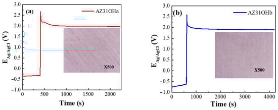
Figure 1.
OCP behaviour for the AZ31 anodising samples using NaOH 1 M as the electrolyte, 3 V polarization to (a) 0.5 and (b) 1 h, respectively.
The naturally formed oxide or passive film present on AZ31 can exhibit high corrosion resistance up to a certain exposure period. However, it may undergo fast corrosion beyond the critical exposure period at which galvanic corrosion is initiated. Therefore, the oxide film formed during the anodising process is more stable, thicker, and reduces the surface reactivity, thereby increasing its corrosion resistance.
The sanding lines (Figure 1a) of AZ31OHa were detected by recording the optical images of the sample surface (inset in Figure 1) because the passive film was thinner. Evidently, the sanding lines of AZ31OHb were smoother than those of AZ31OHa. This behaviour can be attributed to the presence of a thicker Mg(OH)2 passive layer than that of AZ31OHa because of the long anodisation time.
3.1.2. EIS Results (Anodisation)
EIS analysis was performed to investigate the resistive, capacitive, and inductive contributions of each system. All samples were evaluated electrochemically using Hank’s solution, which simulates the biological fluids of the human body. First, the OCP was measured for 10 min before performing the electrochemical impedance test to allow the system to stabilise for AZ31, AZ31OHa, and AZ31OHb. The Nyquist diagrams obtained from the bare sample and those anodised at 0.5 and 1 h polarization time (AZ31, AZ31OHa, and AZ31OHb, respectively) are shown in Figure 2. Evidently, AZ31 exhibited an inductive loop characteristic of magnesium-based alloys at low frequencies; this was associated with its high surface reactivity []. The most widely reported corrosion mechanism [,] involves AZ31 dissolution as a consequence of the oxidation reaction and hydrogen evolution due to the reduction reaction. Additionally, the redox rate reactions were very high and aggressive, and occasionally, the bubbling of hydrogen gas was observed. Nevertheless, the appearance of a low-frequency inductive loop is related to the relaxation of adsorbed anions on the metal surface [,]. Based on this, the presence of Cl ions in the Hank’s solution can increase their adsorption of AZ31.
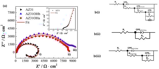
Figure 2.
(a) EIS results for the AZ31 and anodised sample, polarizing 0.5 (AZ31OHa) and 1 h (AZ31OHb), respectively, using HBSS and (b) the equivalent circuits applied in the fitting.
Figure 2 shows the impedance response of AZ31OH at 0.5 and 1 h, where one and two constant times were observed at low frequencies, respectively. AZ31OHa exhibited a single time constant associated with the passive film [Mg (OH)2] obtained by anodising; according to the constant phase element (CPE) values (6 × 10⁻⁶ Ω−1 sn/cm2) from the simulation, this constant time adds resistive contributions, passive film, and charge transfer resistance. By contrast, two constant times were distinguished for AZ31OHb: one was well defined at high frequencies and associated with the passive film [Mg(OH)2], whereas the other was not well defined at low frequencies and corresponded to the electrochemical double-layer resistance (the resistance to charge transfer). Notably, no significant difference was observed in the total impedance values of the system between anodised samples. However, AZ31OHb was more stable and exhibited larger CPE values (8 × 10⁻⁷ Ω−1 sn/cm2) compared with AZ31OHa.
To understand the corrosion behaviour of AZ31, AZ31OHa, and AZ31OHb in the presence of the HBSS, Nyquist plots were analysed using EC-Lab software and fitted using an equivalent circuit to determine the values for each contribution. The equivalent circuits comprising a corrosion environment Rs (electrolyte), resistance of the passive film (Rfilm), and resistance of charge transfer (Rct) were estimated. AZ31 exhibited an inductance (L) associated with the redox reaction owing to the high reactivity of Mg. The CPE was used instead of a capacitive element, (ΥCPE (ω) = 1/ZCPE = Q(jω)n) the Υ admittance of the CPE, where ω is the angular frequency, Q is the modulus, and n is the phase deviation from ideal electrical component behaviour that provides information about surface inhomogeneity. Table 4 lists the fitting parameters of EIS spectra.
Table 4.
Fitting parameters related to EIS spectra are shown in Figure 2.
AZ31 exhibited inductive behaviour, as shown in Figure 2a. The inductive loop was correlated with the high surface reactivity of AZ31, and the presence of Cl− ions in HBSS increased their adsorption by AZ31 (increasing metal oxidation), which consumed electrons from adsorption sites [,]. The inductive loop exhibited characteristic CPE values associated with AZ31 (−5 × 10⁻⁶ Ω−1 sn/cm2) but was negative as presented in Table 4. By contrast, the time constant associated with AZ31OHa (passive film) obtained by anodising exhibited CPE values (6 × 10⁶ Ω−6 sn/cm2) was close to those of AZ31 (2 × 10⁻⁶ Ω−1 sn/cm2). Therefore, this behaviour can be attributed to the addition of the resistive contribution (the passive film and charge–transfer resistance). Additionally, two constant times were identified for AZ31OHb. The first is associated with the passive film [Mg(OH)2] with 8 × 10⁻⁷ Ω−1 sn/cm2 CPE values, whereas the second corresponds to electrochemical double-layer resistance (2 × 10⁻⁷ Ω−1 sn/cm2). This behaviour suggests that the passive film obtained after polarisation for 1 h (AZ31OHb) decreases AZ31 surface reactivity more efficiently, thus increasing its corrosion resistance. This allows subsequent coatings to be obtained more easily.
3.1.3. Polarisation Curve Results (Anodisation)
Polarisation curves were recorded in a potential range (−0.1 to 0.7 V) and are shown in Figure 3. AZ31, AZ31OHa, and AZ31OHb exhibited significant differences, which were reflected primarily in the pitting potential (Epitt) and passivation zone amplitude (ΔEpass).
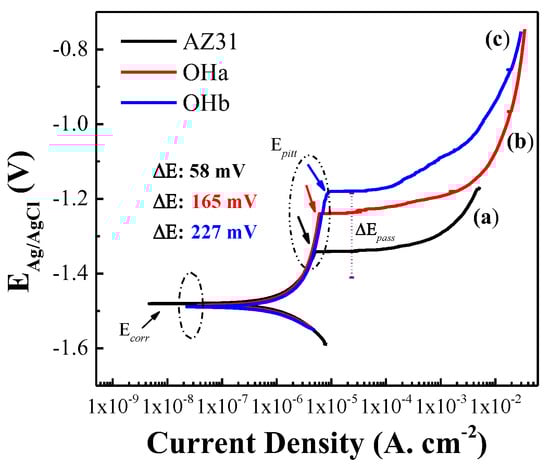
Figure 3.
(CP results for the (a) bare and (b,c) anodized sample, polarizing 0.5 (AZ31OHa) and 1 h (AZ31OHb), respectively, using HBSS.
Taking these variables as a reference, evidently the Epitt shifted toward more positive or noble values, essentially moving from 1.34 V (AZ31) to 1.24 V (AZ31OHa) and 1.16 V (AZ31OHb) in the anodic branch. This behaviour is associated with passive film formation [Mg(OH)2], which provides higher resistance to the pitting corrosion of AZ31OHb compared with AZ31OHa and AZ31. Following the same analysis but considering the passivation zone amplitude (ΔEpass), an increase from 0.058 V (AZ31) to 0.165 V (AZ31OHa) and 0.227 V (AZ31OHb) was observed. Therefore, the obtained passive film on AZ31OHb was more stable and resistant to localised corrosion (pitting).
3.2. Cerium Chemical Conversion Coatings
3.2.1. EIS Results
Figure 4 shows the EIS results of AZ31 anodised to AZ31OHb and the subsequent cerium coating obtained at different concentrations of 0.1, 0.01, and 0.001 M (AZ31OH-CeO2 a, b, and c) in comparison with the reference sample (AZ31). The improvement in the corrosion resistance by CeO2 coating was analysed by EIS (Figure 4a). The Nyquist diagram of AZ31OH-CeO2b exhibited the highest total impedance (30,000 Ω·cm2) compared with the reference sample (3730 Ω·cm2). This behaviour is closely related to the presence of the cerium coating, which sealed the passive film (AZ31OHb), thereby increasing the total impedance of the anodised reference sample.
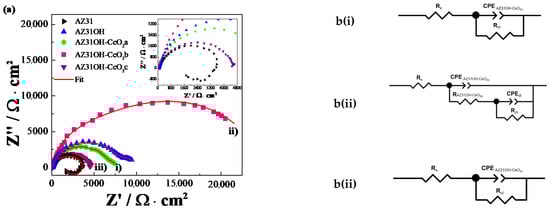
Figure 4.
(a) EIS results for AZ31, anodised sample (AZ31OH), and CeCC coating at 0.1, 0.01, and 0.001 M (AZ31OH-CeO2a, AZ31OH-CeO2b, and AZ31OH-CeO2c), respectively, in Hank’s solution and (b) the equivalent circuits applied in the fitting.
By contrast, the impedances of AZ31OH-CeO2a and AZ31OH-CeO2c were lower than that of AZ31OHb but greater than that of AZ31. The lower impedance of the 0.001 M cerium-coated sample might be due to the lack of cerium ions (i.e., the ions are insufficient to form cerium coatings) or coating defects, such as cracks and pores, whereby the electrolyte can easily pass through the coating and reach the base metal surface, thereby leading to corrosion.
The coating formed on the material of the 0.1 M cerium-coated sample was highly dense and lost surface adhesion. Additionally, previous studies have reported that when cerium coatings are extremely dense, the drying is superficial; thus, the film continues to store moisture inside, and, when it dries, it generates water vapor which induces cracks in the coating, thus weakening it []. This behaviour reduces the coating resistance and allows the easy access of water or aggressive ions. Data from EIS assays were analysed by fitting, and the behaviour of coating with the Hank’s solution was simulated using equivalent circuits. The results are presented in Table 5.
Table 5.
Electrochemical data obtained from equivalent circuit fitting of EIS graphs in Figure 4.
3.2.2. Polarisation Curves Results
Polarisation curves were recorded in a potential range from −0.1 to 0.7 V to determine the electrochemical behaviour of cerium coatings. The polarisation curves of AZ31OH-CeO2 revealed that the layer of hydroxides (OH−) formed on the surface increased the corrosion resistance (Figure 5). However, the contribution of CeO2 was not observed in the form of a potential shift toward a positive direction, in contrast to the OH− coating, thus indicating that more noble corrosion potentials were obtained. This is associated with the solubility of cerium oxides in Hank’s solution. However, it may also be associated with the cathodic character of the CeO2 coating as a corrosion inhibitor [].
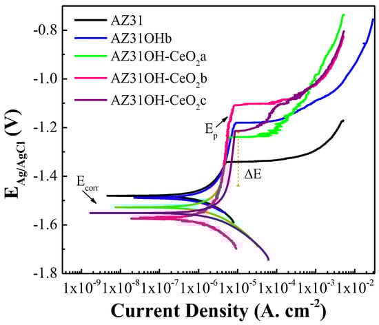
Figure 5.
Polarisation curves of AZ31 and AZ31OHb (1 h anodised time) modified at different concentrations of CeCl2 after being anodised to form AZ31OH-CeO2a, AZ31OH-CeO2b, and AZ31OH-CeO2c, at 0.001 M, 0.01 M, and 0.1 M, respectively.
Nevertheless, the main contribution of cerium coating obtained in the anodic branch was reflected by a greater amplitude of the passive zone (ΔEpass) and a displacement of the pitting potential (Epitt) toward more positive values, as presented in Table 6. The increase in the passive zone of the CeO2 coating can be attributed to the self-healing mechanism. The and Ca groups in the Hank’s solution precipitate until a corrosion product forms on the substrate, primarily generating hydroxyapatite (HA) [].
Table 6.
Electrochemical parameter related to the polarisation curve of AZ31 anodised and modified at different concentrations of Ce2+ ions.
Subsequently, cerium precipitates in the oxide layer through microcracks generated by corrosion reactions [].
In this mechanism, CeO2 is reduced to Ce2O3 by releasing Ce3+ ions; subsequently, these ions diffuse to AZ31, whose surface allows the oxidation of Ce3+ to Ce4+, which is attributed to the passive layer formed on the substrate []. Evidently, AZ31OHb-CeO2b exhibited the most positive pitting potential (−1.11 V) as well as a larger passivation zone (0.386 V) compared with the anodised sample (0.227 V) and reference (0.058 V).
Note that a larger passivation zone is associated with the presence of more stable cerium oxides, such as CeO2, whereas a noble or positive pitting potential indicates that the passive film is more resistant to pitting corrosion [].
Table 6 presents a summary of the behaviour of the samples treated with cerium, the shift in pitting potentials (Epitt), and the amplitude of the passivation zone (ΔEpass) described earlier. Evidently, the results of the polarization curves agreed well with the EIS results obtained.
3.3. Morphology
SEM images were obtained to study the surface morphology and elemental distribution of the AZ31, AZ31OH, and AZ31OH-CeO2b. Figure 6a shows the morphology of the AZ31 bare sample with #1200 polishing. Sanding lines oriented uniformly along a single direction were detected. The elemental distribution in the bare sample through EDS revealed the presence of 86.2 wt% Mg, 2.3% Al, and 0.6% Zn in the alloy. Additionally, the presence of O was detected as a result of the spontaneous oxidation of Mg in the surrounding environment. For the AZ31OH (anodized) sample (Figure 6b), the incorporation of a passive OH layer increased the O content to 46.9 wt%, whereas the Mg content decreased to 41 wt%; further, the presence of Al and Zn was confirmed.
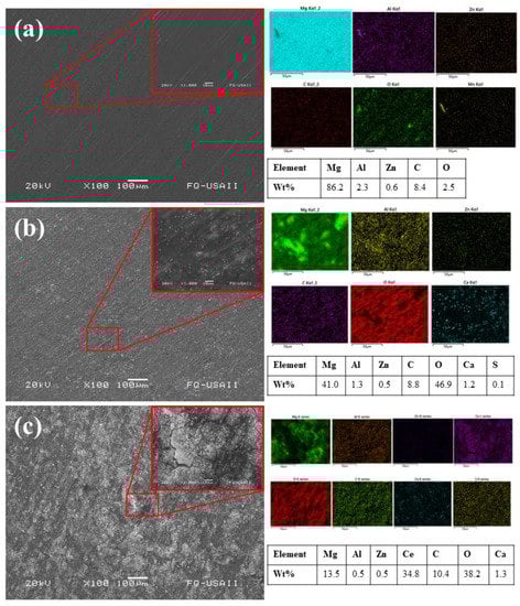
Figure 6.
SEM micrography of (a) AZ31, (b) anodised AZ31OH, and (c) AZ31OH-CeO2.
The micrograph corresponding to the modified sample AZ31OH-CeO2b (Figure 6c) revealed a cracked surface with considerably more cracks compared with the anodised sample, which were probably caused by cerium oxide nucleation at the grain boundaries of the first Mg layer of oxide/hydroxides. This can be due to the reactions involved in the coating process with the precursor CeCl3·7H2O and the presence of H2O2, which causes dehydration or stress in the passive layer. H2O2 was added to the conversion solution as an oxidising agent to produce a more homogenous deposit. The presence of H2O2 increased the deposition rate and conversion layer thickness with a cracked mud structure owing to the stress induced in coating during the drying step. Some heterogeneities such as sanding lines (surface preparation) were still visible as a consequence of the presence of more active sites covered by a thinner coating. EDS mapping indicates that the coating was composed of cerium oxide with 34.8 wt% Ce and 38.2 wt% O; however, Mg was shielded and its content was estimated to be 13.5 wt% on the surface.
3.4. Crystal Structure of Passive Film and CeO2 on AZ31
The XRD patterns of AZ31, AZ31OH, and modified AZ31OH-CeO2b are shown in Figure 7. The Mg characteristic peaks of AZ31 were located at 2θ values of 32.18°, 34.39°, 36.61°, 47.81°, 57.37°, 68.63°, and 70.01°, associated with the (100), (002), (101), (102), (110), (112), and (201) crystallographic planes, respectively (JCPDS 01-089-7195). These peaks have been identified and are related to the specific presence of the α-Mg phase [].
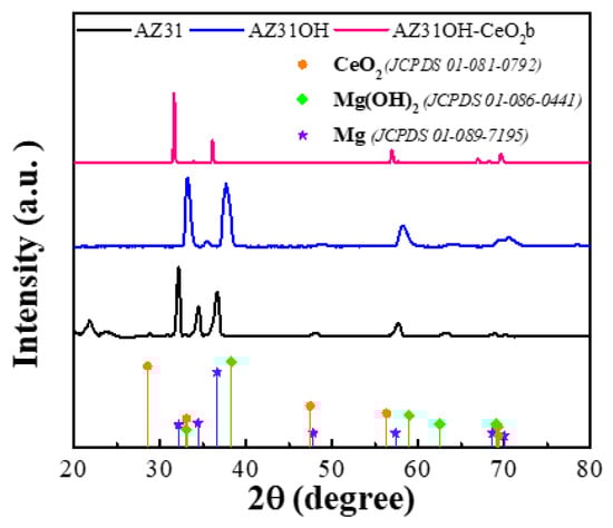
Figure 7.
XRD pattern of AZ31 (substrate), AZ31OH anodised [Mg(OH)2 film], and AZ31OH-CeO2, cerium coating.
The AZ31OH diffractogram exhibited two peaks at 33.01 (100) and 38.28 (011) of Mg(OH)2. However, a specific and characteristic peak reported for Mg(OH)2 at approximately 18.82° did not appear, probably because the passive film [Mg(OH)2] had a smaller thickness. Therefore, the Mg peaks of the substrate were stronger.
Note that determining the characteristic thin peaks of the CeO2 coating was challenging owing to the X-ray diffraction equipment configuration (grazing incidence). This behaviour might be owing to strong peroxide bonds in Ce(O2)(OH)2 in solution, which hinder the precipitation of large CeO2 crystals and impede growth owing to the presence of mixed oxide/hydroxide phase(s) of Ce and Mg at the coating/metal interface [], thus preventing the growth of the CeO2 film. Therefore, detecting CeO2 peaks via XRD was challenging. Nevertheless, the XRD pattern of AZ31OH-CeO2b exhibited peaks with a smaller breadth compared with those of AZ31 and AZ31OH, thus indicating a finite CeO2 crystal size. Minor peaks associated with the CeO2 coating appeared at 2θ values of 33.07°, 56.33°, and 79.06°, assigned to the (200), (311), and (420) crystal planes, respectively (JCDPS 01-081-0792). These peaks have already been identified and are related primarily to the presence of CeO2 [].
3.5. Biocompatibility
MC3T3-E1 pre-osteoblasts’ cell viability and morphology on AZ31, AZ31OH, and AZ31OH-CeO2b modified discs were evaluated by staining the cells cultured on each metallic surface with calcein–AM and Hoecht reagents (Figure 8), which stain live and dead cells, respectively. The calcein–AM dye stains intact and viable cells as the ester groups in the dye molecule are removed by intracellular esterases and converted into a fluorescent green compound. Hoechst is a fluorescent dye that labels DNA and is used to stain the nuclei of dead cells as its permeability in live cells is very low [].
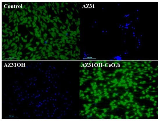
Figure 8.
Fluorescence microscopy of MC3T3-E1 cell viability determined by calcein–AM/Hoechst staining after 24 h on AZ31, AZ31OH, and AZ31OHCeO2b discs.
Figure 8 shows a comparative live/dead study of pre-osteoblast cultures on different materials, analysing the results at 24 h incubation time. MC3T3-E1 cells cultured in the absence of any material were used as the control. The pre-osteoblasts culture in the control assays exhibited a culture in good conditions as almost no dead cells (blue colour) were observed. Cells in the control exhibited the characteristic morphology of pre-osteoblasts, with elongated cells shaped with typical extensions called filopodia []. When the pre-osteoblasts culture was exposed to AZ31, a dramatic change was observed in the behaviour of the culture as no live cells were observed. Essentially, the few cells that were on the metal surface appeared as clumps of dead cells. This is probably owing to the high reactivity of Mg with the cell culture medium, which produced CaCO3, MgCl2, Mg(CO3)2, Mg3(PO4)2, and H2 gas degradation products that affect cell viability due to pH alkalinisation and corrosion [,]. The anodisation of AZ31 produced a clear change in cell distribution on the metallic surface as pre-osteoblasts cells cultured on this surface (AZ31OH) exhibited a dispersed and more uniform cell distribution on the metallic surface compared with AZ31. This suggests an improvement in surface passivation, probably due to the enhancement of hydrophilic character that can affect cell adhesion to the metal surface []. However, no live cells (green) were detected on AZ31OH and only dead cells (blue) were observed, thus indicating the lack of biocompatibility of this material. Nevertheless, significant and completely different results were observed when AZ31OH was coated with cerium oxide (AZ31OH-CeO2b); essentially, pre-osteoblast cells were all live cells, as indicated by the high green fluorescence, and only a few dead cells were observed. Thus, these results were comparable to those of the control (in the absence of any material). This confirms the good biocompatibility of AZ31 anodised by modification with cerium oxide.
4. Conclusions
In this study, the AZ31-Mg-based alloy was coated with CeO2 to determine the effect of coating on corrosion protection and biocompatibility. To reduce the surface activity of the AZ31 bare sample and promote CeO2 coating formation, a Mg(OH)2 layer was deposited through anodisation. EIS and CP electrochemical results demonstrated that the Mg(OH)2 passive film obtained by applying 3 V at 1 h using NaOH 1 M produced a more homogenous, thicker, and electrochemically more stable passive film, which increased its corrosion resistance by approximately one order of magnitude.
The SEM–EDS results corroborated the contribution of the polarisation time in the anodising process; AZ31OHb exhibited fainter sanding lines, which could be associated with the formation of a more homogenous and thicker passive film of Mg(OH)2.
Furthermore, EIS and CP revealed that the CeO2 coating obtained at 0.01 M exhibited better electrochemical behaviour in Hank’s solution. Cerium coating sealed the passive film (AZ31OH), thus increasing the total corrosion resistance compared with AZ31. SEM/EDS revealed that cerium coating had a cracked-mud surface owing to the induced stress in the coating during the drying step.
Finally, the analysis of live cells/dead cells show that the incorporation of CeO2 conferred biocompatibility to AZ31OH-CeO2b. This property could be related to the fact that CeO2 mimics the activity of metalloenzymes, such as superoxide dismutase (SOD) or catalase (CAT), which decrease reactive oxygen species due to the structural configuration (Ce3+/Ce4+), thus favouring the osteoblast proliferation necessary for bone repair.
Author Contributions
S.E.B.-S.: conceptualization, writing—original draft, investigation, and methodology; R.M.L.-P.: funding acquisition, supervision, analysis, and writing—review and editing; and E.O.-B.: funding acquisition, project administration, supervision, and writing—review and editing. All authors have read and agreed to the published version of the manuscript.
Funding
This work was financed by a Consejo Nacional de Ciencia y Tecnología (CONACYT) Science Grant. SIP project 20221194 through the Instituto Politécnico Nacional. Financial support from ICOOP 2021 Ref COOPA20479 of the Consejo Superior de Investigaciones Científicas (CSIC) and from the Spanish Ministry of Science, Innovation and Universities (RTI2018-101506-B-C31C33) is gratefully acknowledged.
Data Availability Statement
Not applicable.
Acknowledgments
Instituto Politécnico Nacional; Consejo Nacional de Ciencia y Tecnología (CONACYT); Consejo Superior de Investigaciones Científicas (CSIC) and the Spanish Ministry of Science, Innovation and Universities is gratefully acknowledged.
Conflicts of Interest
The authors declare no conflict of interest.
References
- Nakano, T. Mechanical properties of metallic biomaterials. In Metals for Biomedical Devices; Elsevier: Amsterdam, The Netherlands, 2010; pp. 71–98. [Google Scholar] [CrossRef]
- Sheikh, Z.; Najeeb, S.; Khurshid, Z.; Verma, V.; Rashid, H.; Glogauer, M. Biodegradable Materials for Bone Repair and Tissue Engineering Applications. Materials 2015, 8, 5744–5794. [Google Scholar] [CrossRef] [PubMed]
- Chen, Y.; Xu, Z.; Smith, C.; Sankar, J. Recent advances on the development of magnesium alloys for biodegradable implants. Acta Biomater. 2014, 10, 4561–4573. [Google Scholar] [CrossRef] [PubMed]
- Henderson, S.E.; Verdelis, K.; Maiti, S.; Pal, S.; Chung, W.L.; Chou, D.-T.; Kumta, P.N.; Almarza, A.J. Magnesium alloys as a biomaterial for degradable craniofacial screws. Acta Biomater. 2014, 10, 2323–2332. [Google Scholar] [CrossRef] [PubMed]
- Salehi, G.; Behnamghader, A.; Mozafari, M. Cellular response to metal implants. In Handbook of Biomaterials Biocompatibility; Elsevier: Amsterdam, The Netherlands, 2020; pp. 453–471. [Google Scholar] [CrossRef]
- Eliaz, N. Corrosion of Metallic Biomaterials: A Review. Materials 2019, 12, 407. [Google Scholar] [CrossRef] [PubMed]
- Xin, Y.; Huo, K.; Tao, H.; Tang, G.; Chu, P.K. Influence of aggressive ions on the degradation behavior of biomedical magnesium alloy in physiological environment. Acta Biomater. 2008, 4, 2008–2015. [Google Scholar] [CrossRef] [PubMed]
- Prasad, S.V.S.; Singh, S.; Prasad, S.B. A review on the corrosion process in magnesium. AIP Conf. Proc. 2021, 2341, 040008. [Google Scholar] [CrossRef]
- Esmaily, M.; Svensson, J.E.; Fajardo, S.; Birbilis, N.; Frankel, G.S.; Virtanen, S.; Arrabal, R.; Thomas, S.; Johansson, L.G. Fundamentals and advances in magnesium alloy corrosion. Prog. Mater. Sci. 2017, 89, 92–193. [Google Scholar] [CrossRef]
- Chen, J.; Tan, L.; Yu, X.; Etim, I.P.; Ibrahim, M.; Yang, K. Mechanical properties of magnesium alloys for medical application: A review. J. Mech. Behav. Biomed. Mater. 2018, 87, 68–79. [Google Scholar] [CrossRef]
- Qin, Y.; Wen, P.; Guo, H.; Xia, D.; Zheng, Y.; Jauer, L.; Poprawe, R.; Voshage, M.; Schleifenbaum, J.H. Additive manufacturing of biodegradable metals: Current research status and future perspectives. Acta Biomater. 2019, 98, 3–22. [Google Scholar] [CrossRef]
- Echeverry-Rendon, M.; Allain, J.P.; Robledo, S.M.; Echeverria, F.; Harmsen, M.C. Coatings for biodegradable magnesium-based supports for therapy of vascular disease: A general view. Mater. Sci. Eng. C 2019, 102, 150–163. [Google Scholar] [CrossRef]
- Amukarimi, S.; Mozafari, M. Biodegradable magnesium-based biomaterials: An overview of challenges and opportunities. MedComm 2021, 2, 123–144. [Google Scholar] [CrossRef] [PubMed]
- Zhang, T.; Wang, W.; Liu, J.; Wang, L.; Tang, Y.; Wang, K. A review on magnesium alloys for biomedical applications. Front. Bioeng. Biotechnol. 2022, 10, 106. [Google Scholar] [CrossRef] [PubMed]
- Cuartas-Marulanda, D.; Cardozo, L.F.; Restrepo-Osorio, A.; Fernández-Morales, P. Natural Coatings and Surface Modifications on Magnesium Alloys for Biomedical Applications. Polymers 2022, 14, 5297. [Google Scholar] [CrossRef] [PubMed]
- Lorenz, C.; Brunner, J.G.; Kollmannsberger, P.; Jaafar, L.; Fabry, B.; Virtanen, S. Effect of surface pre-treatments on biocompatibility of magnesium. Acta Biomater. 2009, 5, 2783–2789. [Google Scholar] [CrossRef]
- Li, L.; Gao, J.; Wang, Y. Evaluation of cyto-toxicity and corrosion behavior of alkali-heat-treated magnesium in simulated body fluid. Surf. Coat. Technol. 2004, 185, 92–98. [Google Scholar] [CrossRef]
- Rahman, M.; Dutta, N.K.; Choudhury, N.R. Magnesium Alloys With Tunable Interfaces as Bone Implant Materials. Front. Bioeng. Biotechnol. 2020, 8, 564. [Google Scholar] [CrossRef]
- Loukil, N. Alloying Elements of Magnesium Alloys: A Literature Review. In Magnesium Alloys Structure and Properties; IntechOpen: London, UK, 2022. [Google Scholar] [CrossRef]
- Hughes, A.E.; Gorman, J.D.; Paterson, P.J.K. The characterisation of Ce-Mo-based conversion coatings on Al-alloys: Part I. Corros. Sci. 1996, 38, 1957–1976. [Google Scholar] [CrossRef]
- Lu, V.M.; McDonald, K.L. Lanthanum nanoparticles to target the brain: Proof of biodistribution and biocompatibility with adjuvant therapies. Nanomedicine 2020, 15, 2107–2117. [Google Scholar] [CrossRef]
- Brabu, B.; Haribabu, S.; Revathy, M.; Anitha, S.; Thangapandiyan, M.; Navaneethakrishnan, K.R.; Gopalakrishnan, C.; Murugan, S.S.; Kumaravel, T.S. Biocompatibility studies on lanthanum oxide nanoparticles. Toxicol. Res. 2015, 4, 1037–1044. [Google Scholar] [CrossRef]
- Zhang, Q.; Xia, X.; Chen, P.; Xiao, P.; Zhou, W.; Li, Y. Current research art of rare earth compound modified SiC-CMCs for enhanced wet-oxygen corrosion resistance. Ceram. Int. 2022, 48, 24131–24143. [Google Scholar] [CrossRef]
- Huang, P.; Zou, B.; Zhang, Y.; Niu, X.; Wang, Y. Synthesis of rare earth silicate thermal barrier coating materials (YxYb2-xSiO5) and application on the surface of titanium alloy. Inorg. Chem. Commun. 2022, 135, 109129. [Google Scholar] [CrossRef]
- Mousavi, B.; Farvizi, M.; Rahimipour, M.R.; Pan, W. Comparison of the hot corrosion behavior of the LZ, CSZ and LZ/CSZ composite thermal barrier coating. Surf. Coat. Technol. 2022, 437, 128324. [Google Scholar] [CrossRef]
- El Shafei, K.; Al Nasiri, N. Corrosion behaviour of rare-earth monosilicates in CMAS exposure. Corros. Sci. 2022, 202, 110312. [Google Scholar] [CrossRef]
- Haider, S.K.; Kim, D.; Kang, Y.S. Four-step eco-friendly energy efficient recycling of contaminated Nd2Fe14B sludge and coercivity enhancement by reducing oxygen content. Sci. Rep. 2021, 11, 22255. [Google Scholar] [CrossRef]
- Hinton, B.R.W. Corrosion inhibition with rare earth metal salts. J. Alloys. Compd. 1992, 180, 15–25. [Google Scholar] [CrossRef]
- Olivier, M.; Lanzutti, A.; Motte, C.; Fedrizzi, L. Influence of oxidizing ability of the medium on the growth of lanthanide layers on galvanized steel. Corros. Sci. 2010, 52, 1428–1439. [Google Scholar] [CrossRef]
- Buchheit, R.G.; Mamidipally, S.B.; Schmutz, P.; Guan, H. Active Corrosion Protection in Ce-Modified Hydrotalcite Conversion Coatings. Corrosion 2002, 58, 3–14. [Google Scholar] [CrossRef]
- Czekanska, E.; Stoddart, M.; Richards, R.; Hayes, J. In search of an osteoblast cell model for in vitro research. Eur. Cell. Mater. 2012, 24, 1–17. [Google Scholar] [CrossRef]
- Fagali, N.S.; Madrid, M.A.; Maceda, B.T.P.; Fernández, M.E.L.; Puerto, R.M.L.; de Mele, M.F.L. Effect of degradation products of iron-bioresorbable implants on the physiological behavior of macrophages in vitro. Metallomics 2020, 12, 1841–1850. [Google Scholar] [CrossRef]
- Salman, S.A.; Mori, R.; Ichino, R.; Okido, M. Effect of Anodizing Potential on the Surface Morphology and Corrosion Property of AZ31 Magnesium Alloy. Mater. Trans. 2010, 51, 1109–1113. [Google Scholar] [CrossRef]
- Feliu, S. Electrochemical Impedance Spectroscopy for the Measurement of the Corrosion Rate of Magnesium Alloys: Brief Review and Challenges. Metals 2020, 10, 775. [Google Scholar] [CrossRef]
- Jang, Y.; Collins, B.; Sankar, J.; Yun, Y. Effect of biologically relevant ions on the corrosion products formed on alloy AZ31B: An improved understanding of magnesium corrosion. Acta Biomater. 2013, 9, 8761–8770. [Google Scholar] [CrossRef] [PubMed]
- Tkacz, J.; Slouková, K.; Minda, J.; Drábiková, J.; Fintová, S.; Doležal, P.; Wasserbauer, J. Influence of the Composition of the Hank’s Balanced Salt Solution on the Corrosion Behavior of AZ31 and AZ61 Magnesium Alloys. Metals 2017, 7, 465. [Google Scholar] [CrossRef]
- Ruhi, G.; Modi, O.P.; Singh, I.B. Corrosion behaviour of nano structured sol-gel alumina coated 9Cr–1Mo ferritic steel in chloride bearing environments. Surf. Coat. Technol. 2009, 204, 359–365. [Google Scholar] [CrossRef]
- Tomcsányi, L.; Varga, K.; Bartik, I.; Horányi, H.; Maleczki, E. Electrochemical study of the pitting corrosion of aluminium and its alloys—II. Study of the interaction of chloride ions with a passive film on aluminium and initiation of pitting corrosion. Electrochim. Acta 1989, 34, 855–859. [Google Scholar] [CrossRef]
- Han, L.; Zhang, Z.; Dai, J.; Li, X.; Bai, J.; Huang, Z.; Guo, C.; Xue, F.; Chu, C. The influence of alternating cyclic dynamic loads with different low frequencies on the bio-corrosion behaviors of AZ31B magnesium alloy in vitro. Bioact. Mater. 2022, 7, 263–274. [Google Scholar] [CrossRef]
- Chelliah, N.M.; Padaikathan, P.; Kumar, R. Evaluation of electrochemical impedance and biocorrosion characteristics of as-cast and T4 heat treated AZ91 Mg-alloys in Ringer’s solution. J. Magnes. Alloy. 2019, 7, 134–143. [Google Scholar] [CrossRef]
- Jayaraj, J.; Rajesh, K.R.; Raj, S.A.; Srinivasan, A.; Ananthakumar, S.; Dhaipule, N.G.K.; Kalpathy, S.K.; Pillai, U.T.S.; Mudali, U.K. Investigation on the corrosion behavior of lanthanum phosphate coatings on AZ31 Mg alloy obtained through chemical conversion technique. J. Alloys. Compd. 2019, 784, 1162–1174. [Google Scholar] [CrossRef]
- Chaudry, U.M.; Farooq, A.; Tayyab, K.B.; Malik, A.; Kamran, M.; Kim, J.-G.; Li, C.; Hamad, K.; Jun, T.-S. Corrosion behavior of AZ31 magnesium alloy with calcium addition. Corros. Sci. 2022, 199, 110205. [Google Scholar] [CrossRef]
- Pham, D.N.; Hiromoto, S.; Kobayashi, E.M.O. Influence of substrate microstructure on hydroxyapatite coating and corrosion behavior of coated Mg Zn alloys. Surf. Coat. Technol. 2021, 421, 127414. [Google Scholar] [CrossRef]
- Yao, Q.-S.; Zhang, F.; Song, L.; Zeng, R.-C.; Cui, L.-Y.; Li, S.-Q.; Wang, Z.-L.; Han, E.-H. Corrosion resistance of a ceria/polymethyltrimethoxysilane modified Mg-Al-layered double hydroxide on AZ31 magnesium alloy. J. Alloys. Compd. 2018, 764, 913–928. [Google Scholar] [CrossRef]
- Zhao, Y.; Zhang, Z.; Shi, L.; Zhang, F.; Li, S.; Zeng, R. Corrosion resistance of a self-healing multilayer film based on SiO2 and CeO2 nanoparticles layer-by-layer assembly on Mg alloys. Mater. Lett. 2019, 237, 14–18. [Google Scholar] [CrossRef]
- Poinern, G.E.J.; Brundavanam, S.; Fawcett, D. Biomedical Magnesium Alloys: A Review of Material Properties, Surface Modifications and Potential as a Biodegradable Orthopaedic Implant. Am. J. Biomed. Eng. 2013, 2, 218–240. [Google Scholar] [CrossRef]
- Kamde, M.A.; Mahton, Y.; Ohodnicki, J.; Roy, M.; Saha, P. Effect of cerium-based conversion coating on corrosion behavior of squeeze cast Mg-4 wt% Y alloy in 0.1 M NaCl solution. Surf. Coat. Technol. 2021, 421, 127451. [Google Scholar] [CrossRef]
- Scholes, F.H.; Soste, C.; Hughes, A.E.; Hardin, S.G.; Curtis, P.R. The role of hydrogen peroxide in the deposition of cerium-based conversion coatings. Appl. Surf. Sci. 2006, 253, 1770–1780. [Google Scholar] [CrossRef]
- Payandeh, M. Rheocasting of Aluminium Alloys: Slurry Formation, Microstructure, and Properties; Jönköping University, School of Engineering: Jönköping, Sweden, 2015. [Google Scholar]
- Carter, S.-S.D.; Barbe, L.; Tenje, M.; Mestres, G. Exploring microfluidics as a tool to evaluate the biological properties of a titanium alloy under dynamic conditions. Biomater. Sci. 2020, 8, 6309–6321. [Google Scholar] [CrossRef]
- Sammons, R. Biological responses to hydroxyapatite. In Hydroxyapatite (Hap) for Biomedical Applications; Elsevier: Amsterdam, The Netherlands, 2015; pp. 53–83. [Google Scholar] [CrossRef]
- Peron, M.; Skaret, P.C.; Fabrizi, A.; Varone, A.; Montanari, R.; Roven, H.J.; Ferro, P.; Berto, F.; Torgersen, J. The effect of Equal Channel Angular Pressing on the stress corrosion cracking susceptibility of AZ31 alloy in simulated body fluid. J. Mech. Behav. Biomed. Mater. 2020, 106, 103724. [Google Scholar] [CrossRef]
- Gonzalez, J.; Lamaka, S.V.; Mei, D.; Scharnagl, N.; Feyerabend, F.; Zheludkevich, M.L.; Willumeit-Römer, R. Mg Biodegradation Mechanism Deduced from the Local Surface Environment under Simulated Physiological Conditions. Adv. Healthc. Mater. 2021, 10, 2100053. [Google Scholar] [CrossRef]
- Hsu, C.; Nazari, M.H.; Li, Q.; Shi, X. Enhancing degradation and corrosion resistance of AZ31 magnesium alloy through hydrophobic coating. Mater. Chem. Phys. 2019, 225, 426–432. [Google Scholar] [CrossRef]
Disclaimer/Publisher’s Note: The statements, opinions and data contained in all publications are solely those of the individual author(s) and contributor(s) and not of MDPI and/or the editor(s). MDPI and/or the editor(s) disclaim responsibility for any injury to people or property resulting from any ideas, methods, instructions or products referred to in the content. |
© 2023 by the authors. Licensee MDPI, Basel, Switzerland. This article is an open access article distributed under the terms and conditions of the Creative Commons Attribution (CC BY) license (https://creativecommons.org/licenses/by/4.0/).