Article

Robot-Assisted Cold and Warm Incremental Sheet Forming of Aluminum Alloy 6061: A Comparative Study

1
Department of Mechanical Engineering, IIT (BHU), Varanasi 221005, India
2
Department of Mechanical Engineering, Marwadi University, Rajkot 360003, India
3
Department of Mechanical Engineering, Vel-Tech Rangarajan Dr Sagunthala R&D Institute of Science and Technology, Avadi, Chennai 600062, India
4
Department of Industrial Engineering, College of Engineering, King Saud University, P.O. Box 800, Riyadh 11421, Saudi Arabia
5
Department of Mechanical Engineering, Campus Santiago, University of Aveiro, 3810-193 Aveiro, Portugal
*
Author to whom correspondence should be addressed.
Metals 2023, 13(3), 568; https://doi.org/10.3390/met13030568
Submission received: 9 January 2023 / Revised: 4 March 2023 / Accepted: 6 March 2023 / Published: 11 March 2023
(This article belongs to the Special Issue Innovative and Flexible Sheet Forming Technologies)

Abstract

:
Incremental sheet forming (ISF) requires no or partial dies for sheet metal fabrication and is widely used for small batch production. In this process, necking is either suppressed or delayed due to the localized nature of tool–sheet contact; hence, more strains than conventional stamping and deep drawing are obtained. In the present study, two variations of ISF, namely cold ISF (CISF) and warm ISF (WISF), are compared. First, FEA modeling is carried out on ABAQUS to reach the forming forces involved in the process. It is found that WISF reduces the forming forces. The temperature for WISF is maintained at 180 °C. Following the simulation analysis, tests are carried out. The forming force in WISF is 55.77% less than that in CISF. The part fabricated by CISF is slightly more substantial than that by WISF; however, more forming depth can be achieved by WISF. There is a more uniform thickness distribution in the case of CISF than in WISF. However, the surface quality of the CISF product is inferior to that of WISF. It is observed that there is reduced forming force, increased formability, and better strain distribution in WISF compared to CISF. However, post-processing heat treatment and surface polishing of the formed parts is required to restore their mechanical properties.

1. Introduction

Incremental sheet forming is a non-conventional process of sheet forming in which no dedicated dies are used for sheet forming. This process is specifically helpful for small batch production of complex three-dimensional shapes. The concept of this process is directly based on additive manufacturing and 3D printing, which are widely used globally. In this process, a sheet is formed in a stepwise manner without using any dedicated dies; there are only partial dies. This process is also called dieless forming. The sheet is deformed in a stepwise incremental way where a small area undergoes deformation at a time, and the deformation moves over the entire product. Deformation in ISF is gradual, localized, and incremental, which are found to be responsible for increased limiting strain.
Additionally, due to localized contact between the sheet and tool, the friction is also less, and more strain is induced before the onset of necking. This process has attracted the aerospace, automotive, and biomedical sectors to manufacturing complex sheet metal components [1,2]. This process was used by Iseki et al. [3] for small batch production of non-symmetrical shallow shells using path-controlled spherical rollers [4] in the last two decades. In this process, necking is either suppressed or delayed, resulting in higher strains than in conventional stamping, deep drawing, and stretching processes [5]. In addition to this, there are other advantages over traditional forming methods:
(a) The process does not require dedicated dies, and the setup cost can be vastly reduced.
(b) The degree of flexibility of the process is relatively high as different shapes are formed by changing the tool path. New profiles are quickly produced by changing the programming for the tool path.
(c) The deformation zone in ISF is confined, due to which stress becomes localized and enhanced formability is achieved. The uniformity of thickness throughout the deformed region is one of the critical factors in improving the formability of sheet metal forming processes. Kim and Park demonstrated that shear deformation is one factor for improved product formability [6,7].
(d) The process of ISF forms the basis for rapid prototyping because of its stepwise deforming nature.
(e) The process is energy-efficient, and the products can be recycled. Therefore, it becomes a robust process for small batch production in the automotive, aerospace, and biomedical sectors.
Researchers claim that in the ISF process, more formability in the sheet is observed due to the complex nature of the stress state involving shearing, stretching, bending under tension, and cyclic straining, which leads to uniform strain distribution in the sheet undergoing deformation. Emmens and Boogaard [8] found strains in ISF much higher than in conventional processes such as deep drawing, stretching, and stamping. The enhancement of formability is due to the localized nature of deformation because of the small tool–sheet contact area, which leads to the suppression or delay of necking. Emmens and Boogard also concluded that formability is enhanced in ISF due to the stresses’ complex nature. There were six factors: contact stress, bending under tension, shear, cyclic straining, the geometrical inability of the neck to grow, and hydrostatic pressure related to ISF. Among these, contact stress, bending-under-tension, and shear localize the deformation, whereas shear, cyclic straining, and the geometrical inability of neck growth postpone the unstable development of a neck [8,9].
To assess the formability of the sheet in ISF, the straight groove test proposed by Kim and Park has been used [10]. Shim and Park [11] used a straightforward groove test for formability analysis in ISF. A straight groove was made on the sheet marked with circular grid patterns, and the forming limit curve (FLC) was plotted for the same; a straight line with a negative slope in the region of positive minor strain was observed. The FLC for ISF was found to be above the FLC for conventional sheet metal forming processes. In the early years of ISF, the process was carried out using a 5/6 axis CNC machine; the tool path program was fed to the CNC machine drive, and the sheet was deformed to the shape according to the provided schedule. However, in the recent past, industrial robotic arms have been used to perform ISF, and the process is termed as Robot-Assisted Incremental Sheet Forming (RAISF). The process was patented by Tuominen [12] in 2004. Since then, the use of Industrial Robotic arms has been frequently reported. Robotic arms offer various advantages over CNC machines in terms of better speed control, higher accuracy, and a larger workspace. Mohanty et al. [13] used RAISF for forming steeper wall angles, providing tilt and rotation to the part, and found that giving a slant to the amount to be fabricated leads to a higher forming grade [13,14,15].
Numerous attempts have been made to improve the quality of the product formed by ISF. Various factors affect ISF such as forming force, formability, spring back, and surface finish. Gatea et al. [9] presented a detailed review of the effect of process parameters in ISF. They analyzed the impact of various parameters, temperature, number of stages in forming, tool diameter, step size, and feed rate, on the formability, accuracy, and spring back in the formed product. Temperature plays a very significant role in ISF, and generally, temperature positively affects formability in the ISF process. Several works have been carried out to deform sheets in warm and hot conditions. The setup is provided with an additional heating arrangement to achieve better formability. Duflou et al. [16] developed a laser-assisted ISF machine in which arrangements were made for the local heating of the sheet using a 500 W ND-YAG laser. It was discovered that both forming force and spring back were reduced. In addition to these, the residual stress was also found to be reduced in the case of laser-assisted ISF.
Similarly, Gottmann et al. [17] used a 10 kW fiber-coupled diode laser emitting laser light coaxially aligned with the forming tool, and the deformation was performed with simultaneous heating of the sheet. The sheet of Ti-6Al-4V was deformed, and the final depth was more than that of cold forming. Fan et al. [18] used an electric current heating system to deform magnesium alloy. They observed a maximum formability of 64.30 at a present value of 500 A and a feed rate of 1000 mm/min. Too low a feed rate causes sheet burning, whereas, at too fast a feed rate, there is not enough time to soften the sheet. It was also found that with a small tool diameter (<6 mm), the heat causes localized burning of the sheet, and with a giant tool diameter, heat becomes spread, and proper heating of the sheet does not occur. Palumbo and Brandizzi [19] used static heating with high spindle speeds to deform Ti sheets. High spindle speed is found to stabilize the neck. They deformed a Ti sheet at a temperature of 400 °C and used it for manufacturing the car doors.
Similarly, Najafabady and Ghaei [20] used hot incremental forming (HISF) to deform the Ti-6Al-4V sheet to a basic conical and pyramidal shape, and observed the effect of different process parameters on the dimensional accuracy, surface quality, and work hardening of the fabricated workpieces. There was a deviation from the ideal geometry, which was found to be maximum at the tip and considerably decreased a few millimeters away from the tip. The roughness of the inner surface, where the tool contacted the workpiece, was greater than that of the outer surface. Micro-hardness showed that the hardness increased from the flange to the vertex of the workpiece, where more considerable plastic deformation and, hence, more work hardening is expected to occur.
Similarly, Al-Obaidi et al. [21] used the setup with induction heating to deform DP 980 sheet, DC04 steel sheet, and 22MnB5 steel to achieve a high degree of deformation. Ambrogio et al. [22] used HISF on aluminum AA2024-T3, magnesium AZ31B-O, and titanium Ti6Al4V alloys. The molybdenum disulfide MoS2 was used as a lubricant in all the experiments. They noticed an increase in the formability by local heating of the sheet. As a result, the formability of the aluminum AA2024-T3 increased from 300 to 600, the final formability of magnesium AZ31B-O was found to be 400, and the formability of Ti6Al4V rose from 200 to 450. The surface finish was found to be reduced with the increase in wall angle. Singh et al. used radiation heating to locally heat the Al 1050 sheet. They found a delay in fracture and intensification of the formability with the elevated-temperature incremental forming process compared to that of the incremental forming process at room temperature [23]. Wankhede et al. [24] fabricated an Al 2016-T6 sheet at an elevated temperature of 250 °C using a coil for local heating and found a 956% rise in sheet formability. Kumar et al. [25] used radiation heating to perform ISF on CP titanium grade 2 sheet, and an FE simulation and experimental work were used to investigate the process capabilities of a CP-Ti Grade-2 sheet formed through warm incremental sheet forming (WISF) in terms of thickness distribution, forming forces, geometrical accuracy, and surface roughness. They found increased formability, reduced forming forces, and better thickness distribution in the case of ISF at an elevated temperature of 100 °C [26].
HISF has advantages over cold ISF in terms of reduced force and better formability. It can be used for Ti and Mg sheets whose formability at room temperature is less. However, performing ISF at high temperatures has some associated drawbacks; hot ISF requires sophisticated arrangements to be mounted on the ISF setup. Performing ISF at high temperatures can affect the surface qualities of the formed product. While forming sheets of lower strength, it can be helpful to perform WISF to take advantage of both cold and hot ISF. Recently, WISF has been used to exploit its full potential. Ghiotti and Bruschi [27] used WISF to fabricate Mg alloy AZ31B at 1500 and 2500 and found that fabricated parts had better formability. Azpen et al. [28] used friction stir ISF on 6061-T6 aluminum alloy sheets and concluded that tool diameter influences surface roughness. Zhang et al. [29,30] used oil bath heating to perform WISF on the AZ31B sheet. They found that the most significant factors affecting the formability are forming temperature, step depth, and sheet thickness in decreasing order. Bouhamed et al. also discussed the formability of functionally graded materials formed by single-point incremental forming [31]. Said et al. [32] discussed the numerical simulation and their single-point tool path generation incrementally formed shapes.
In contrast, tool diameter is a non-significant factor in WISF. The same trend was observed for spring back as well. Recently, Mohanraj et al. [33] performed WISF on magnesium AZ31 and aluminum 6061 alloys and achieved better formability and an exact shape at 300 °C.
From the above literature survey, it is clear that temperature plays a significant role in ISF. It positively affects ISF in terms of improved formability, decreased force, and better accuracy of the formed product. The current work compares cold incremental sheet forming (CISF) and WISF using a simulation on ABAQUS. After successfully simulating both processes on Abaqus, incremental cold sheet forming (CISF) and WISF are performed using a six-axis industrial robotic arm. They are named robot-assisted cold incremental sheet forming (RACISF) and robot-assisted warm incremental sheet forming (RAWISF). The path planning is performed by online programming using a teach pendant. Several shapes are made, and the initiating force, mechanical properties using the uniaxial tensile test, microhardness, and surface finish are compared. It is found that RAWISF shows better process capabilities than RACISF does.
2. Simulation Study

Before experimentation, both WISF and CISF were simulated using Abaqus. The simulation analysis was carried out on a conical shape formed on the Abaqus platform. Three-part instances were created: (a) the forming tool, (b) a plate made of aluminum alloy, and (c) a flange to hold the plate. The material properties of aluminum alloy are given in Table 1.
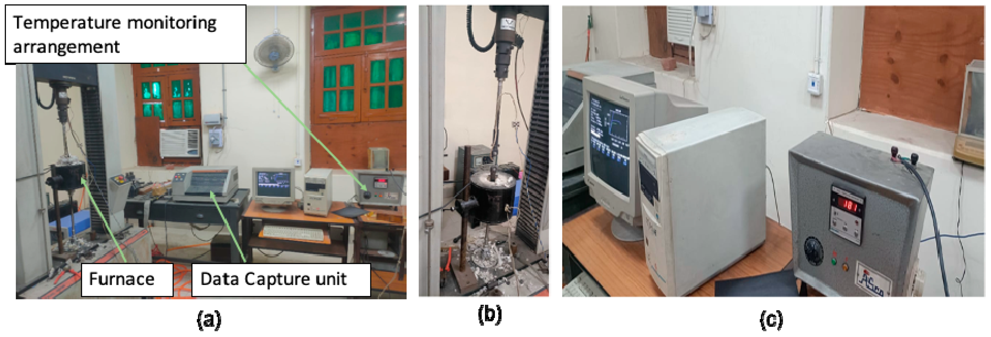
The data for stress–plastic-strain were obtained from the uniaxial tensile test. As tensile properties at different temperature can be different, the tensile test was carried out on a machine, which was equipped with a furnace for heating the sample. The setup for testing is shown in Figure 1.
The stress–strain curve of the samples in the undeformed condition is given in Figure 2a.
Once the tensile properties had been obtained using the tensile test, the respective data for true-stress–true-plastic-strain were used for simulation of CISF and WISF until the maximum load at which necking occurred. The log–log plot of true stress and true strain was extended up to a strain of 1.0, as shown in Figure 2b. The value of the work hardening exponent post-necking was obtained by finding the slope of this segment of the plot.
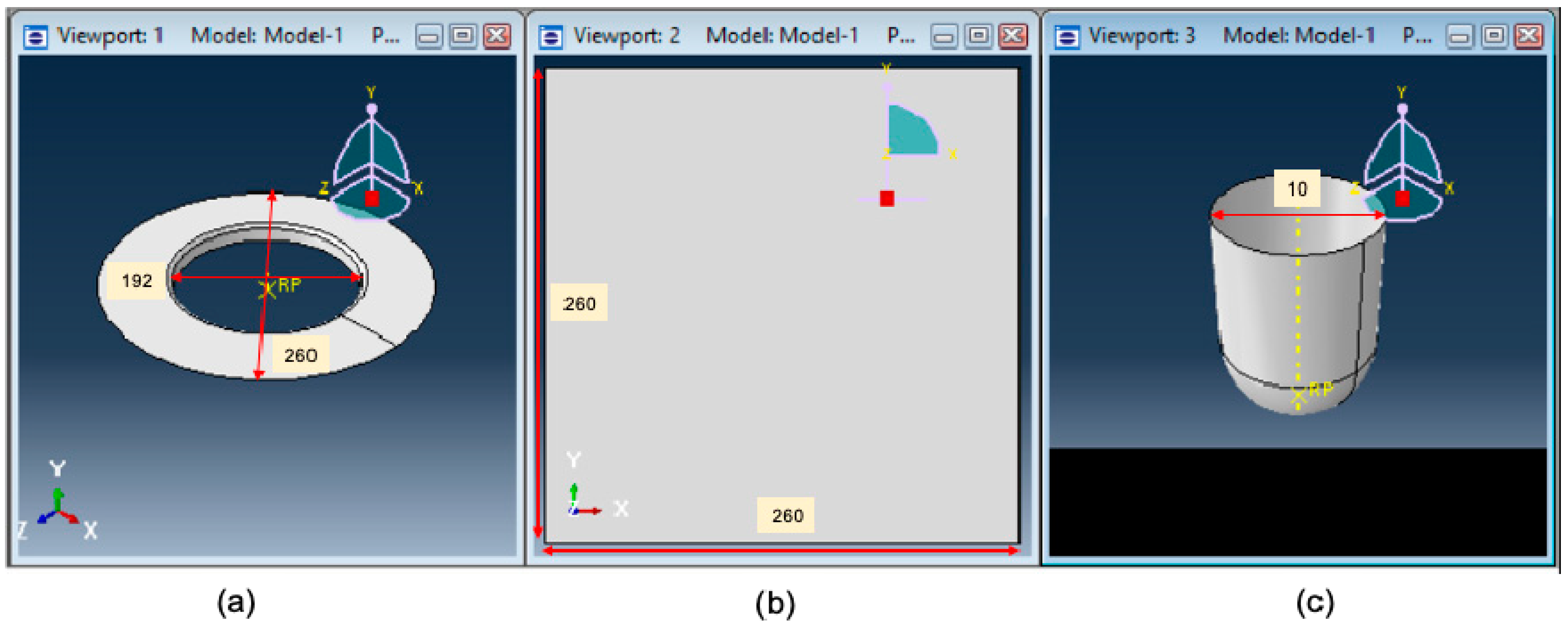
For analysis purposes, isotropic hardening and penalty contact between the tool and sheet were taken. The friction coefficient was taken as 0.2, obtained from the wear test. Square meshing was conducted on the plate with an average mesh size of 6.96 mm. For analysis, the square blank of thickness 1.5 mm was taken. The rigid tool was made, the tool diameter of which was taken as 10 mm. The geometries used with the Abaqus simulation including dimensions of the part are given in Figure 3.
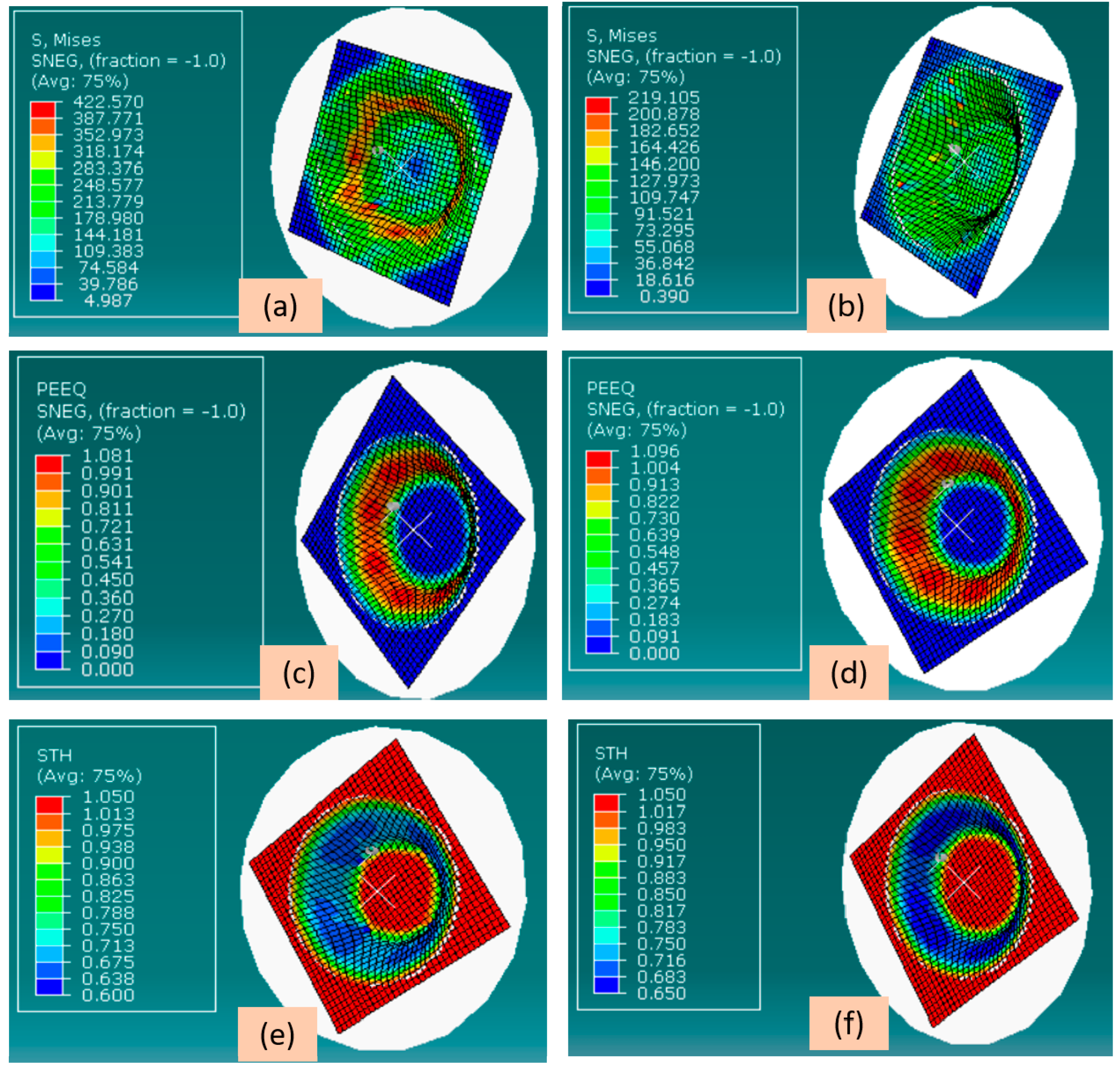
The temperature in the case of WISF forming was maintained at 180 °C. The tool path for both CISF and WISF was generated on MATLAB, and the position coordinates obtained were fed in Abaqus to obtain the conical shape. The simulation was run, and dynamic analysis was carried out for stresses, strains, and tool forces arising during the tool motion, the results of which are given in Figure 4.
It can be seen from Figure 4a,b that the von-Mises stress was most significant in direct contact between the undeformed sheet and the tool for both CISF and WISF. The stress distribution in both cases followed the same trend; however, the von-Mises stress arising in CISF was more than that arising in WISF, which can lower forming forces in the case of WISF. Figure 4c,d illustrate that the most prominent strain occurred in the cone’s middle. In WISF, the strain obtained was slightly more than that in CISF. Further, it can be revealed from Figure 4e,f that the central section of the cone had the minimum thickness, indicating that this region underwent the most outstanding amount of thinning, affirming the distribution shown in Figure 4a–d.

3. Materials and Methodology

After successful FEA analysis of the process on ABAQUS, the experiments were conducted for which sheets of aluminum alloy 6061 with a thickness of 1.05 mm were chosen, as this is the most widely used material in the sheet metal industry. Sheets of the alloy 6061 were solution-heat-treated for 2 h at 415 °C, cooled in a furnace until 260 °C, held for one hour, and finally cooled in the air [34]. The mechanical parameters were obtained from the uniaxial tensile test and the Erichsen ductility test. The composition of the aluminum alloy 6061 was determined by an optical emission spectrometer and is presented in Table 2.
Tensile tests were conducted before the forming to evaluate the tensile properties of the two alloys. ASTM/E8 standard was followed in preparing the samples for the tensile test. Following ASTM/E643/15 standards, specimens for the Erichsen ductility test were prepared.

3.1. Tensile Test

Tensile properties of the sheet of the alloy 6061, before forming into various shapes, are listed in Table 3.

3.2. Erichsen Ductility Test

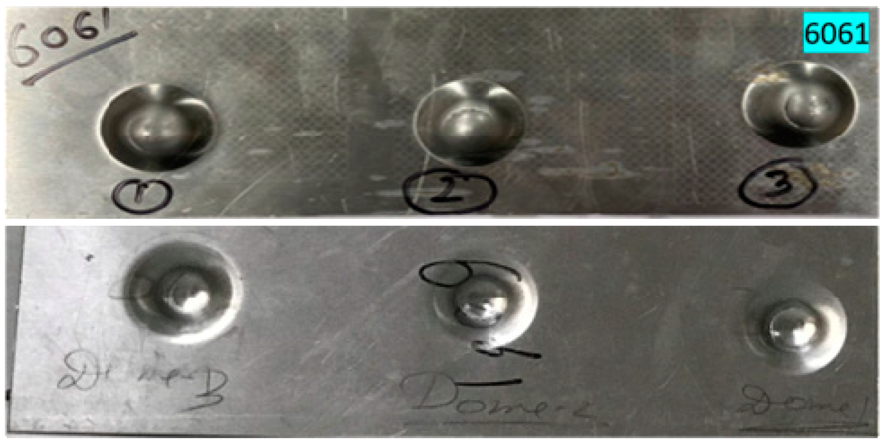
Before selecting a material, it is very crucial to have an idea of its formability. Additionally, as the sheet may undergo strain release once the tool leaves the instantaneous tool–sheet interface, it will spring back, so it is equally important to have an idea of spring back behavior. For the formability prediction of the used sheet, the Erichsen cup test was used at IITBHU. The indenter diameter was 20 mm, the main scale division was 1 mm, and the circular scale division was 50/5MSD. The domes made after the Erichsen ductility test are shown in Figure 5. The Erichsen no (IE) for all the domes was measured, which is given in Table 4. Subsequently, the dome height (Hd) after the samples were released was also measured, the difference was calculated as Δ, and the % change in dome height was calculated, which gives an idea about the spring action of the sheet.

3.3. Experimental Setup

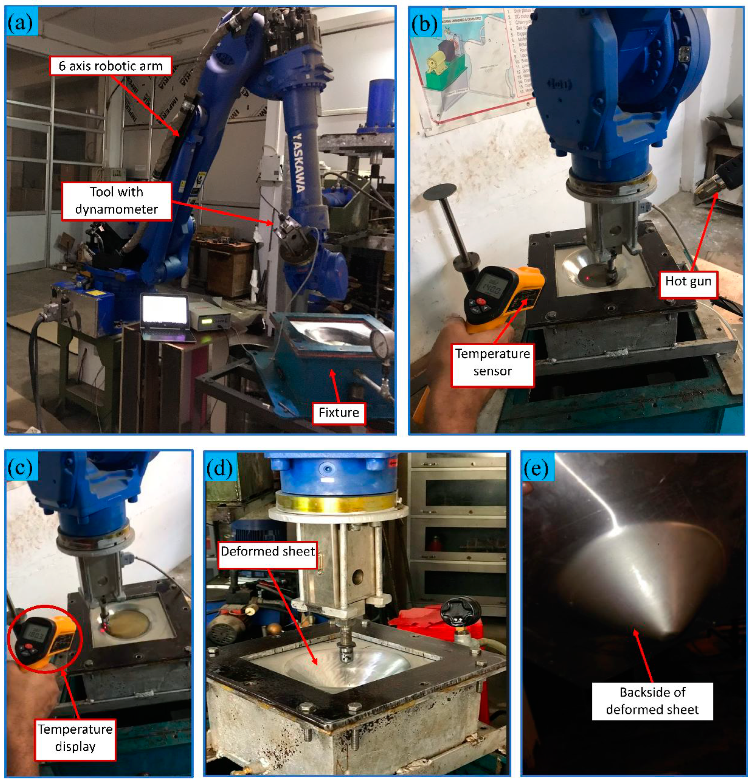
The experimental setup of robot-assisted incremental sheet forming (RAISF) was established from scratch, at the IIT (BHU), in the production engineering lab. The main parts of the setup were (a) a six-axis industrial robot provided by M/s Yaskawa having a payload capacity of 180 kN with a controller and teach pendant; (b) the clamping arrangement; (c) a tool dynamometer for measurement of forming forces; (e) the addition of forming tool(s) for performing RAWISF heating arrangement, which consisted of a heating gun and temperature-measuring infrared thermometer. The sheet was heated to a warm condition using the heating gun, and the infrared thermometer measured the temperature. The schematic diagram for the experimental setup is shown in Figure 6.

3.4. Tool Path Planning

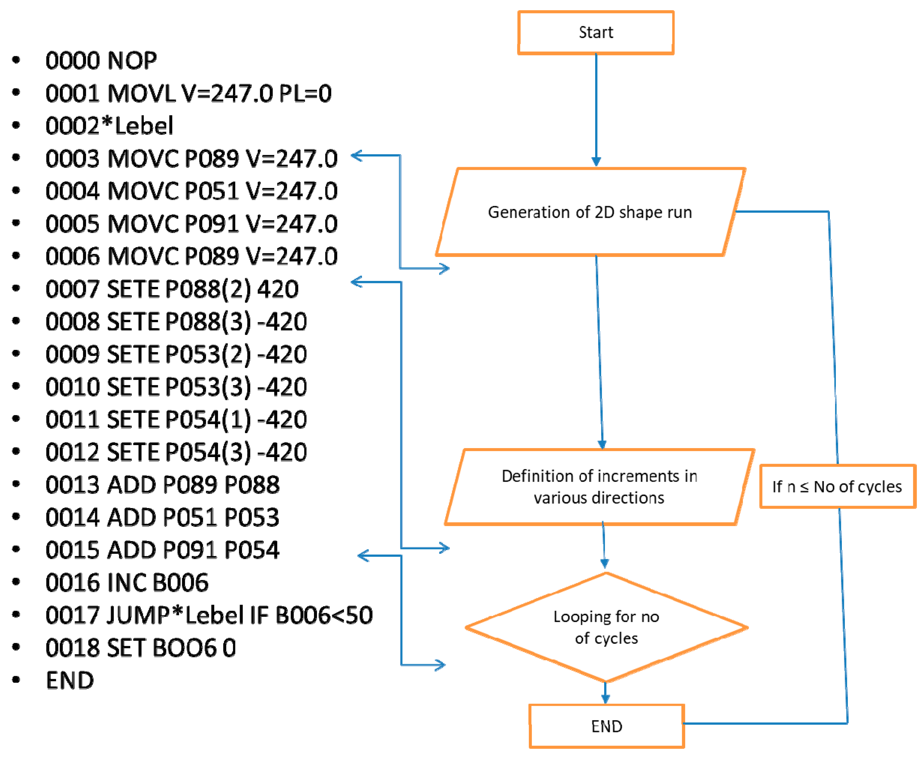
The tool path planning was performed using the online planning method by a teach pendant. The path planning was conducted to make axis-symmetric and non-axis-symmetric shapes. The path planning strategy is given in Figure 7.
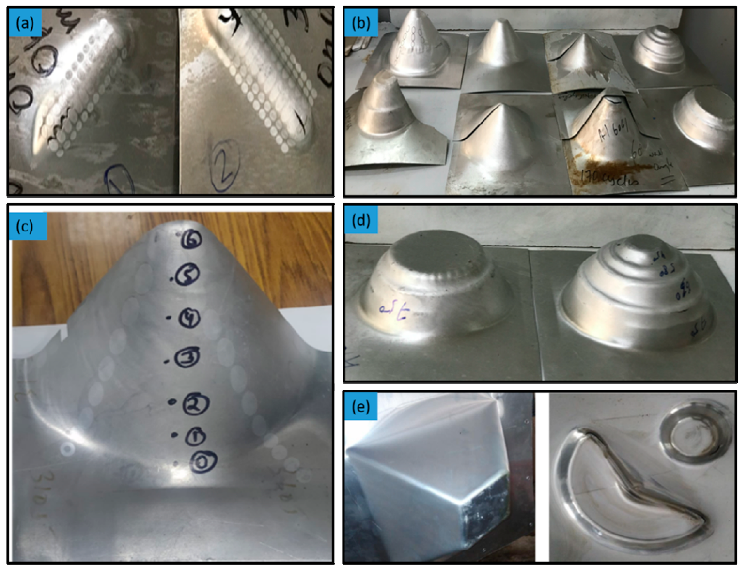
After the sheet was clamped tightly, an online tool path was generated by a teach pendant mounted on a robotic arm for fabricating the sheet into the desired shape. After the tool path was generated, it was tested by giving the tool a dry run. The tool can execute playback of the programmed tool path to fabricate the sheet. Hydraulic oil was used as a lubricant for smooth forming in both processes. In the current work, a fixed ball tool was used as it gives rise to kinetic friction due to localized heating at the tool–sheet contact area, which can soften the sheet, and more considerable deformation can be obtained. A straight groove test was conducted to finalize the input parameters of tool speed, tool diameter, and step depth. A straight groove with a length of 60 mm was made until the onset of fracture by providing linear forward and backward motion to the tool and allowing the tool to travel downward, providing vertical increments at the start and end of each pass. The samples after the straight groove test are shown in Figure 8a. After regression analysis of the outputs obtained from the straight groove test, the input parameters of tool speed, tool diameter, and step depth were chosen and were 247 mm/s, 10 mm, and 0.42 mm, respectively. For RAWISF, a temperature of 180 °C can be conveniently achieved by a hot air gun without needing any sophisticated arrangement to be mounted on a conventional RAISF setup. Once the setup was established, experiments were conducted to form various shapes, shown in Figure 8b–e.
For comparison of formability, a fixed wall angle cone was formed until the onset of fracture. The maximum wall angle achieved in the case of CISF was 68° in single-stage forming and 76° for WISF in single-stage forming. The details of the geometry along with the experimental conditions are summarized in Table 5.
It can be concluded that WISF can achieve more deformation than CISF. Additionally, it was also observed that spring back was reduced in the case of WISF. This may be because of the softening of the sheet at elevated temperatures. However, a 45° wall angle cone was selected for comparison of both processes. Both processes successfully made the cone using the optimized input parameters by the straight groove test, and a tool dynamometer was used to measure the forming force appearing during forming operation.

4. Results and Discussion

4.1. Forming Force

The forming forces appearing in both RACISF and RAWISF were measured using a drill tool dynamometer, and the setup is shown in Figure 6. The capacity of the dynamometer was 500 kgf having a strain-gauge-based 350 Ω bridge sensor. The force was measured in X, Y, and Z directions, and the result of all three components was calculated. The forces measured from experiments and evaluated from simulation analysis were compared by plotting graphs of various force components vs. time.

4.1.1. Comparison of Forces in X Direction (Fx)

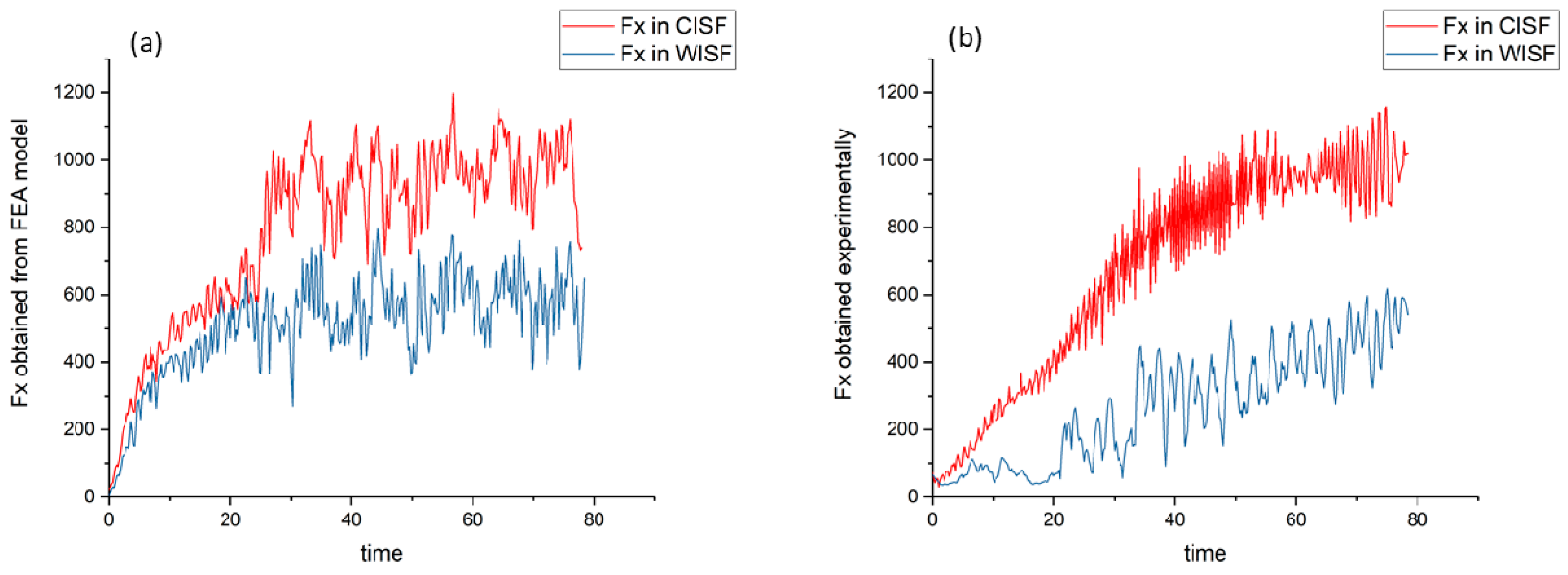
The force in the X direction was evaluated from Abaqus analysis of both CISF and WISF; the force component was measured for both cases experimentally. It was found that the average force in the X direction, in the case of warm forming obtained experimentally, was reduced by 37.05%. The average and peak values of Fx in various cases are given in Table 6.
The variation in Fx in CISF and WISF with time obtained in the FEA model and experimentally is shown in Figure 9a,b, respectively.

4.1.2. Comparison of Forces in Y Direction (Fy)

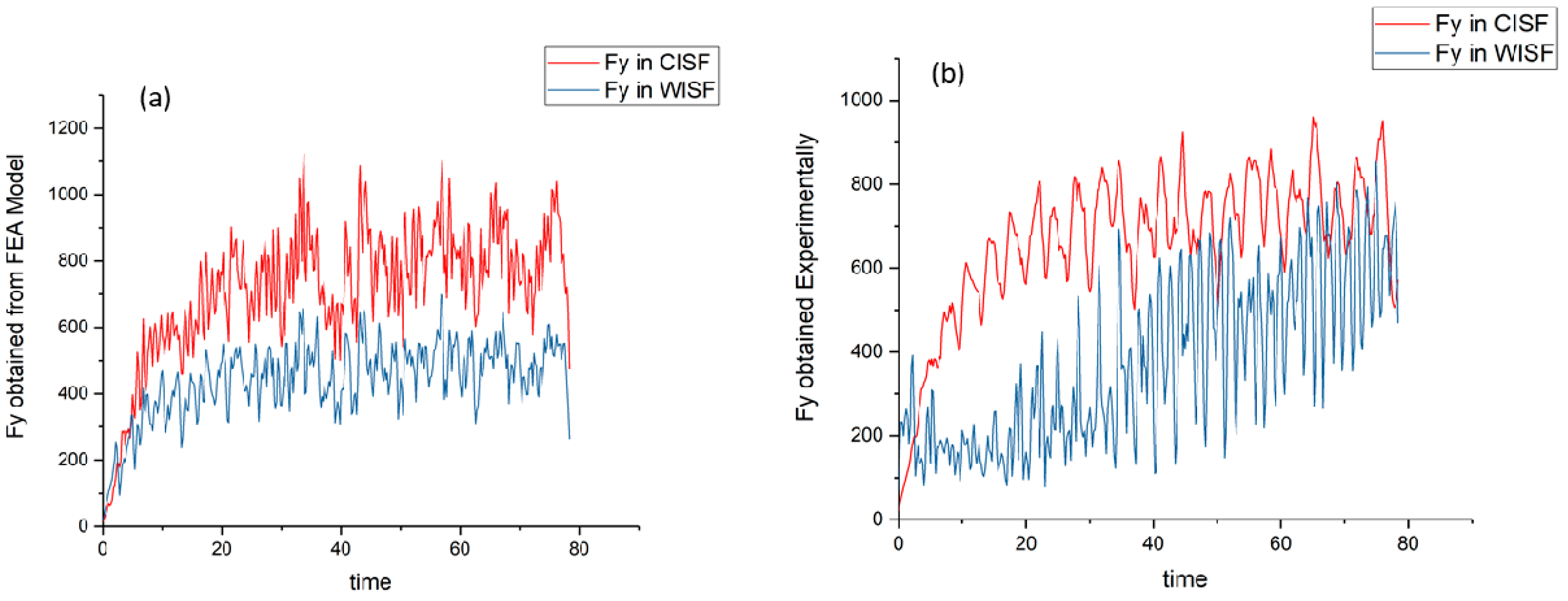
The average force and peak force in the Y direction, obtained in the FEA model and experimentally, are given in Table 7.
As can be seen from Table 6, the average force in the Y direction obtained experimentally decreased by 42.45%, which was also approximately predicted by the FEA model. The variation in Fy in the FEA model and experiments for CISF and WISF with time is shown in Figure 10.

4.1.3. Comparison of Forces in Z Direction (FZ)

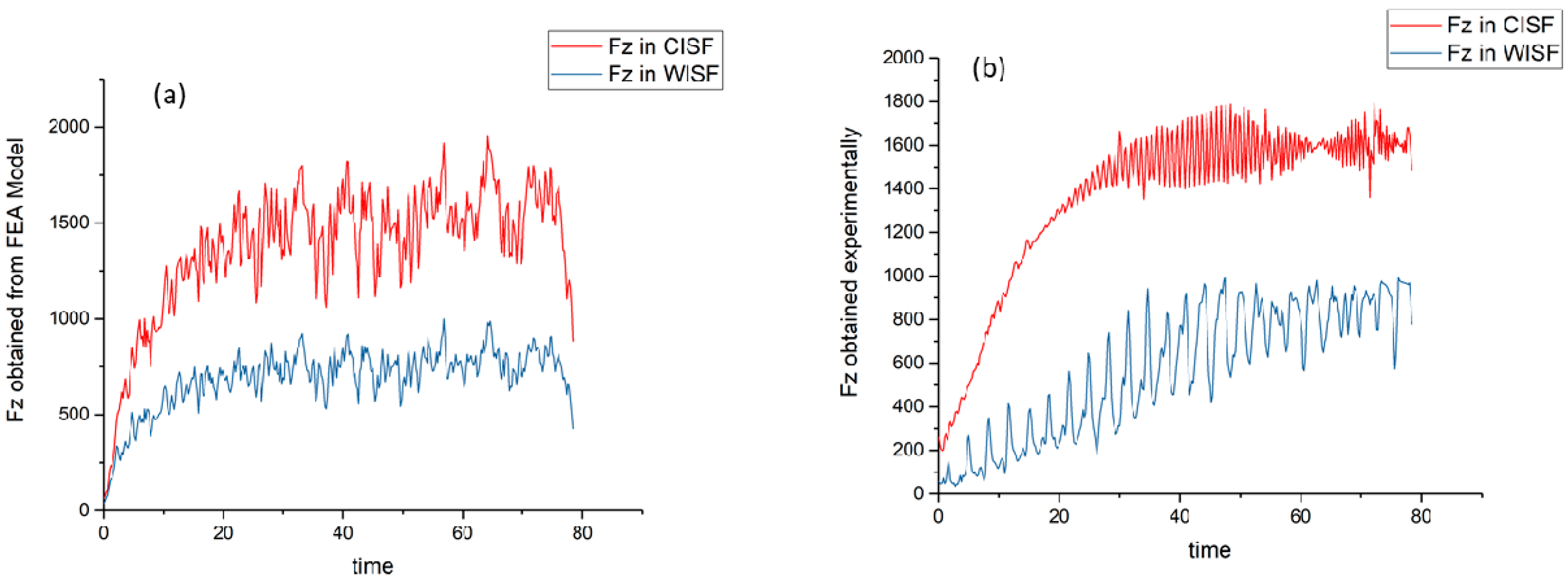
The average force and peak force in the Z direction obtained by the FEA model and experimentally are given in Table 8.
As seen from Table 6, Table 7 and Table 8, the Z-component of the forming force was largest in magnitude. The Z-component of forming force obtained in experiments in the case of warm forming was found to reduce by 53.32%. The variation in FZ in the FEA model and experiments with time is shown in Figure 11.

4.1.4. Comparison of Total Force in CISF and WISF (Ft)

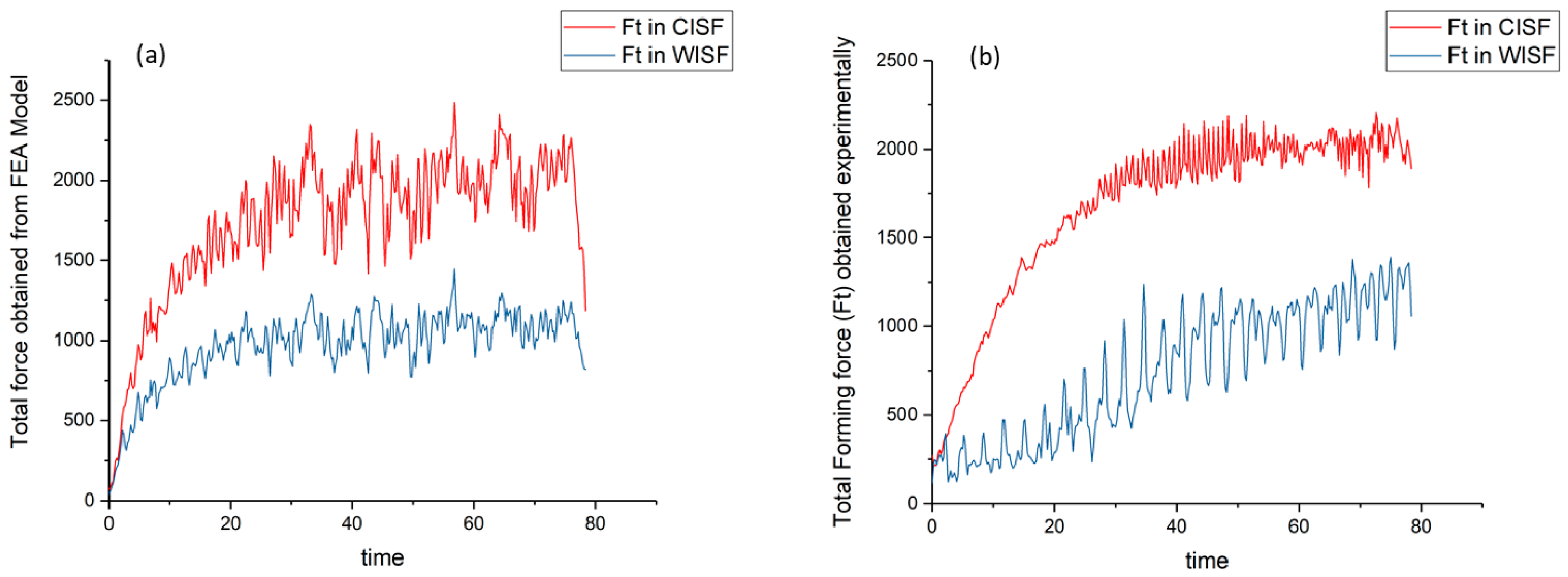
The total forming force was found to decrease in the case of WISF. The loads on drives used in incremental sheet forming can be reduced. The average and peak values of the total forming force (Ft) in FEA and experimental analysis are given in Table 9.
As can be seen from Table 8, the average force obtained in experiments was reduced by 55.77%. The variation in total forming force for CISF and WISF in the case of the FEA model and experiments with time is shown in Figure 12.
It can be observed from Figure 13 that the forming force in the case of cold forming increased steeply at the beginning of the process and then increased at a slower rate and finally stabilized. Almost the same trend was followed in the case of warm forming. The surface plot of all force components Fx, Fy, and Fz in CISF and WISF is shown in Figure 13. It can be seen from Figure 13 that all the components of forces increased during the fabrication of the cone in CISF and WISF. However, the force components in WISF were smaller than those in CISF.

4.2. Tensile Test

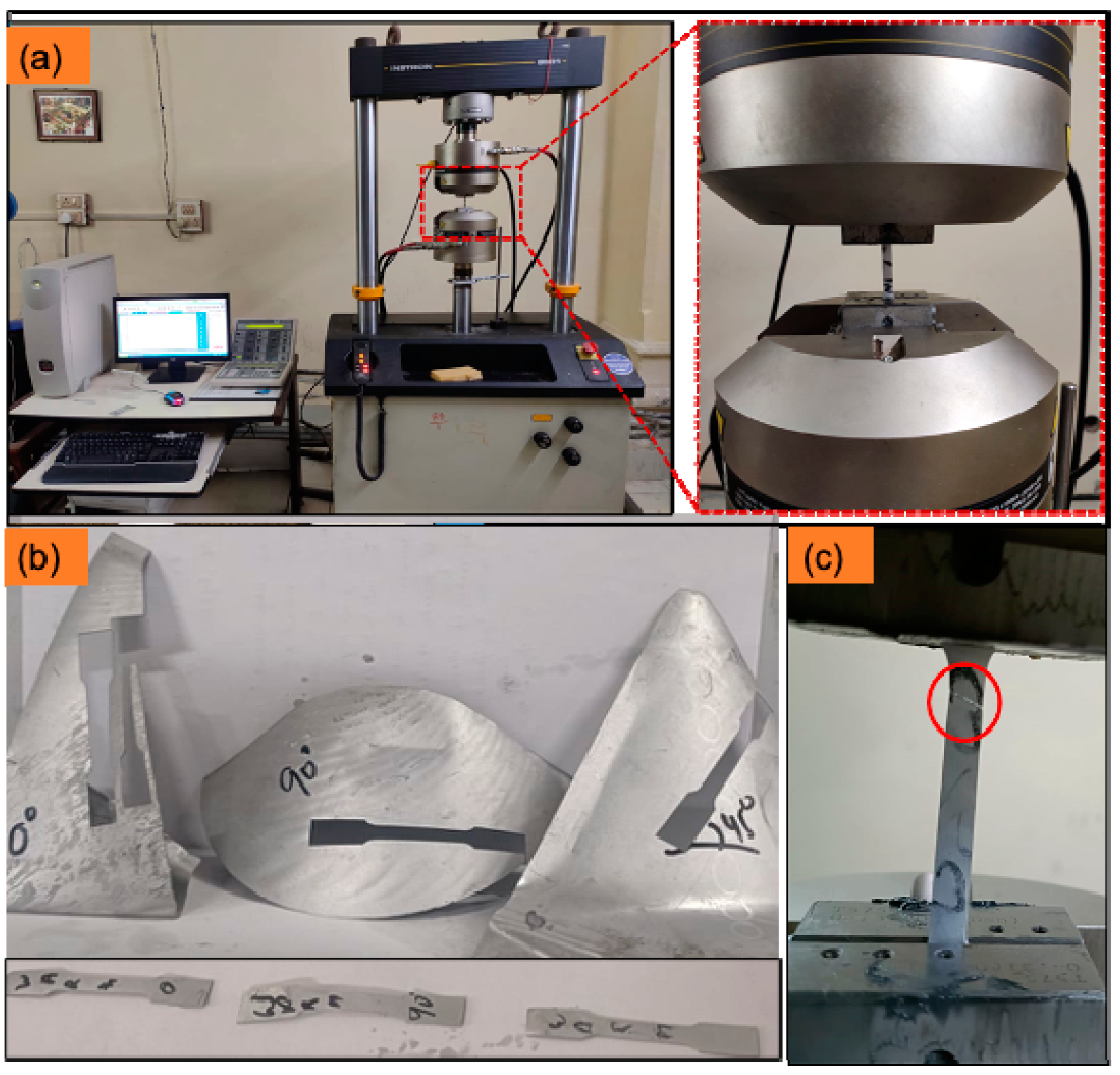
Uniaxial tensile tests were performed using a 100 kN INSTRON (MODEL 8801) universal tensile machine on the samples made from undeformed sheets (Table 2) and the cones formed by the CISF and WISF. The samples were prepared as per the ASTM/E8 standard [35]. The samples from the formed cones were cut in three different directions to examine the anisotropic effect on the formed component, namely (a) along the length of the cone wall to evaluate tensile properties in the meridional directional; (b) along the circumferential direction of tool motion to evaluate the tensile properties in the transverse direction; (c) in a direction 45° to the longitudinal direction along the surface of the cone. The tensile samples cut from the formed cone is illustrated in Figure 14b. Tensile testing was carried out at a crosshead speed of 1 mm/s. Figure 14a displays the specimens mounted on the uniaxial tensile testing and Figure 14c shows the specimen after breakage.
Engineering tensile stress–strain curves and true-stress–true-strain curves of samples are shown in Figure 15. The true stress is shown until UTS in all cases.
The tensile properties evaluated from the tensile test in all three directions are given in Table 10.
It can be observed from Table 10 that the tensile properties were affected by the orientation of test sample. There was a variation in the tensile strength as well ductility of the formed cones with the change in orientation; thus, there was an anisotropic effect in the formed cones and the effect of anisotropy on different parameters was different on the cones formed by CISF and WISF. However, properties obtained for the undeformed, CISF, and WISF sample followed some common trends. It was found out that of the three, the sample from the cone formed by CISF showed the maximum tensile strength. This was due to the higher strain hardening induced in the sheet during cold forming. The strength of the cone formed by WISF exhibited higher ductility than the cone formed by CISF, which can be due to softening of the sheet at elevated temperature. It can be seen from the tensile test that there was a decrease in strength after warm working. Some controlled heat treatments can be given to fabricated parts to restore their strength.

4.3. Microhardness Test

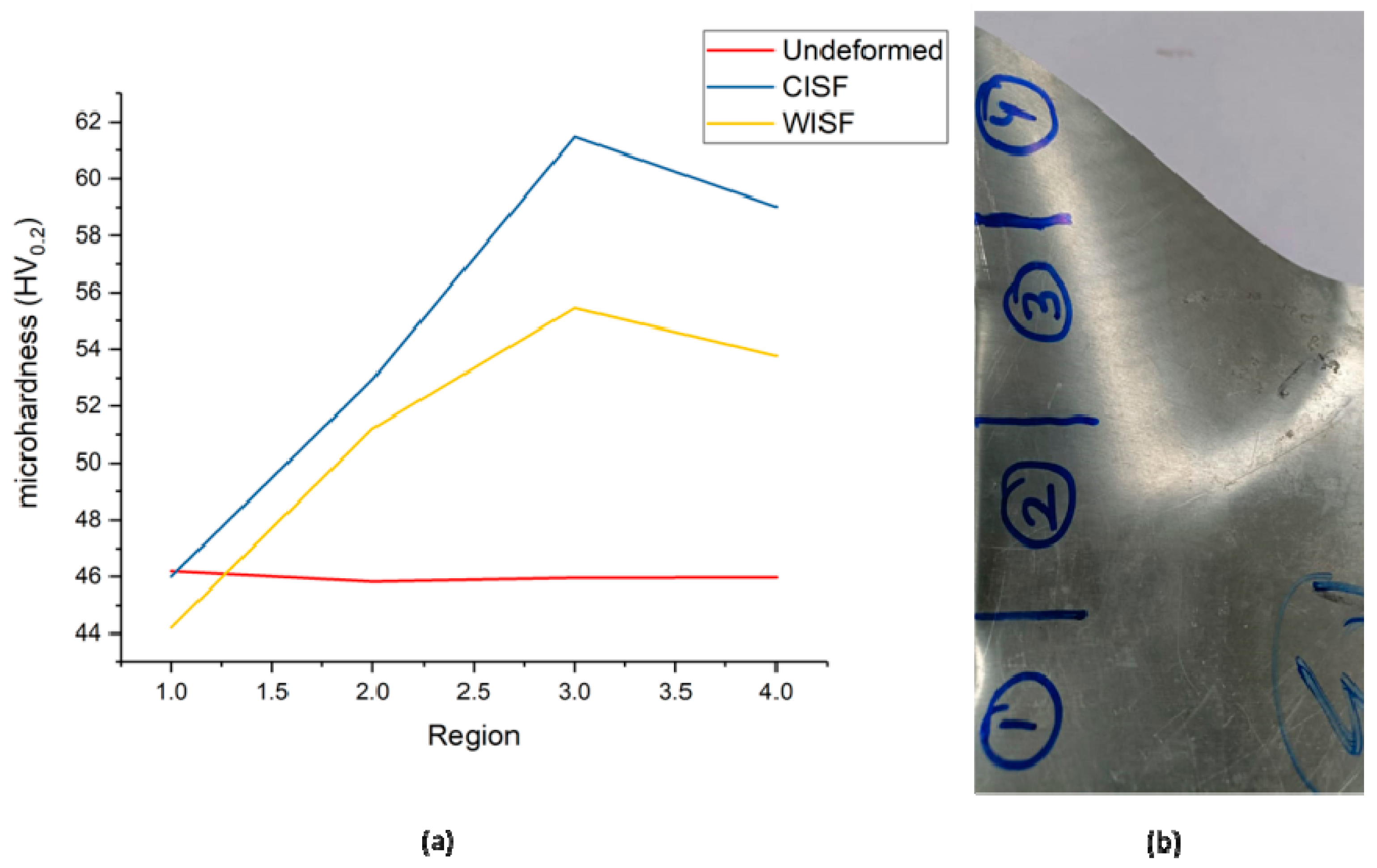
It is crucial for sheet-metal-fabricated items to be solid and rigid. Therefore, the hardness of the sheet following CISF and WISF needs to be evaluated. The microhardness test was conducted using the OMNITECH microhardness testing machine to compare the hardness of the sheet before and after forming the cone. Once the cone was fabricated, the cone was divided into 4 regions, namely 1, 2, 3, and 4. Region 1 was the region of the upper undeformed region of the cone. Region 2, region 3, and region 4 were the cone’s upper, middle, and lower regions, respectively, as shown in Figure 16b. For each region, four microhardness measurements were made at different points on the samples, and an average of the four values was taken as the microhardness of that region. The respective microhardness values of the cones of the aluminum alloy 6061 formed by CISF and WISF are recorded in Table 11, and their graphical representation is given in Figure 16.
It can be revealed from the microhardness test that the microhardness in the CISF formed cone was maximum due to strain hardening because of cold working. Hardness was found to be highest in the middle region of the cone, suggesting that this region had undergone maximum strain and strain hardening. The sample from the cone formed by WISF showed that the microhardness in different regions was less than that in CISF. This test suggests that there can be a loss of hardness of the product formed by WISF, and suitable heat treatment should be given to the fabricated part to increase the strength.

4.4. Thickness Distribution

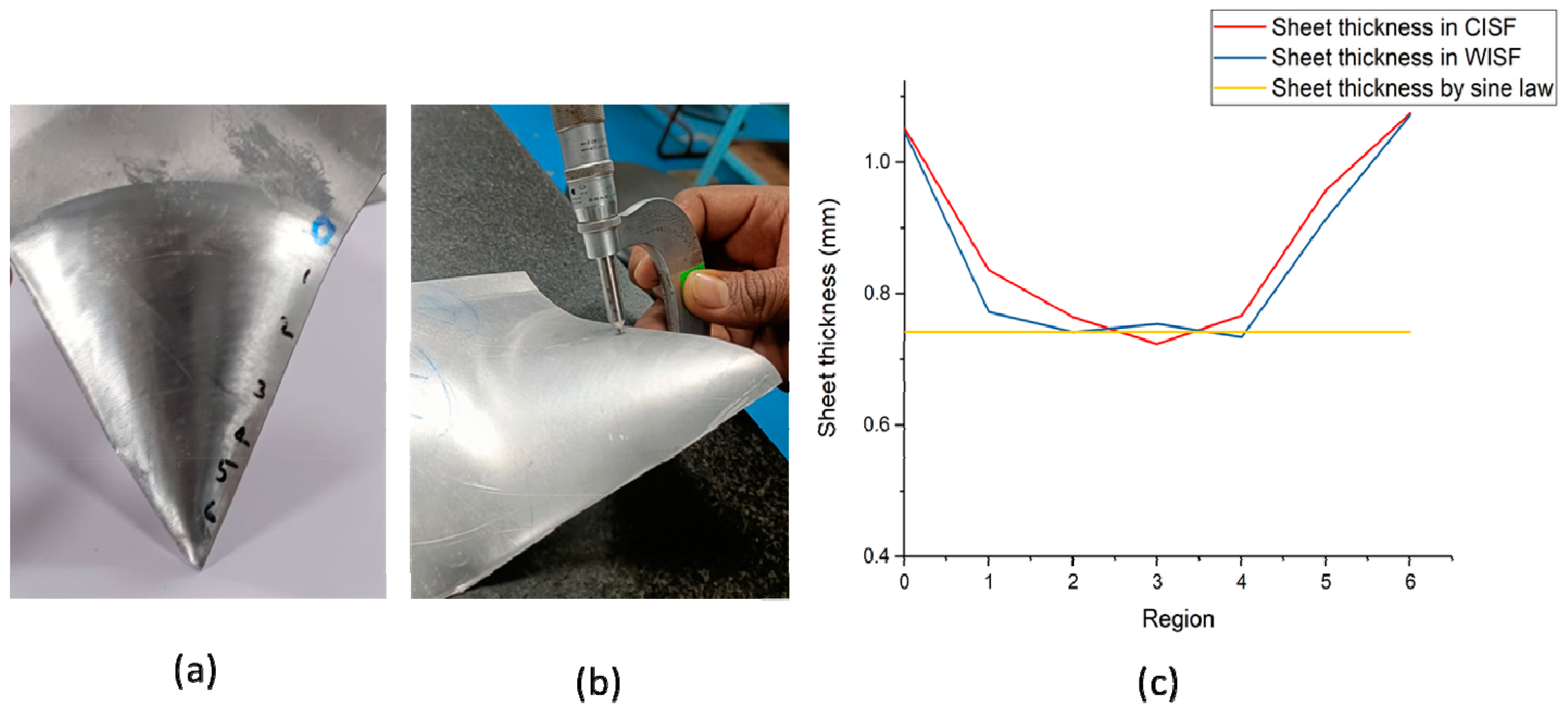
A certain amount of sheet thinning is always associated with the ISF process. The thinning during the ISF process is attributed to thickness strain along the thickness direction. Sheet thickness in the formed cone can be roughly predicted by the famous sine law t = t0 sin θ. Ambrogio et al. [36] showed that the thickness prediction by the sine law is most accurate in the middle region of the formed cone. They further showed that in the region near the sheet surface, the sheet thickness is more than that predicted by the sine law due to the presence of the clamps near the deformation region, and in the region close to the last spire of the sheet, the thickness is less than that predicted by the sine law. To examine the sheet thickness along the wall of the formed cone, the formed region was divided into 7 sub-regions (0–6), as shown in Figure 17a, and the thickness in different regions was measured by a micrometer with a pointed tip (Figure 17b) and with a minor count of 0.001 mm. Region-0 was the undeformed region where the thickness was 1.05 mm, and region-6 was the lower undeformed region where the material accumulates as the tool drags the materials with it. Hence, the sheet thickness exceeded the original sheet thickness. However, regions 1–5 were where sheet thinning occurs. The average sheet thickness tavg (average of thickness in regions 1–5 in both the processes is given in Table 12). The thickness plot for CISF and WISF is given in Figure 17c. The green line shows the thickness predicted by the sine law for spinning (t = t0 sin θ) [37].
It can be seen from Table 9 that the average sheet thickness in the case of CISF was more than that in WISF; however, the distribution of sheet thickness in the middle region of the cone was more uniform in the case of WISF. Hence, warm ISF can provide higher formability to the sheet, and there can be a more uniform thickness distribution in the formed sheet.

4.5. Surface Finish

The roughness of the cones produced by the CISF and WISF methods was measured. An essential component of sheet metal forming operations is a surface finish; hence, the impact of the forming process on the surface finish was examined. To assess the surface quality before and after forming, the surface finish of the inner side and outer side of the cone was measured and compared. As the inner side of the cone remains in direct of the forming tool, this side is likely to be rougher than that of the outer surface. For comparison, the surface that underwent maximum thinning was chosen, and, hence, the sample was taken from region 4, as mentioned in Section 4.3. The test was carried out on the Mitutoyo Surftest SV-2100 machine. The sampling length was 0.8 mm, the number of samplings was 5, and the travel length was 4.8 mm. The surface roughness of the undeformed and deformed sheet was examined by Ra, Rz, and Rq values. The corresponding values were measured by moving the stylus knob over the sample. The measured values are given in Table 13.
It can be seen from Table 10 that the surface finish in the case of CISF was better than that in WISF. However, the variation was not much and can be accepted because of other benefits of WISF over CISF. To verify the same, the contact surface was examined by an atomic force microscope. The AFM surface profile is shown in Figure 18.
It can also be seen from the AFM analysis of the surface shown in Figure 18 that the surface obtained by WISF was of the most inferior quality. WISF affects the surface quality of the formed component; however, the surface is likely to be better than that achieved by hot forming, which can be the subject of further research.

5. Conclusions

In this work, CISF and WISF were performed on aluminum alloy 6061, and the effect of warm forming in ISF was analyzed. FEA analysis was carried out for both processes, and forming forces were calculated using FEA analysis on Abaqus. Experiments were carried out to compare the two processes. Tensile and Erichsen ductility tests were performed to evaluate the tensile properties and formability of the sheets before deformation. Several shapes were made using the two processes, and their properties were compared. Experiments with parameters optimized by a straight groove test were performed, and the following conclusions were drawn.
Warm forming significantly reduced the forming forces.
Warm forming enhanced the formability of the sheet, as evident from the larger wall angle of the cone formed by WISF.
The strength of the product formed by CISF was higher than that formed by WISF; however, ductility increased in WISF, and WISF can achieve a higher formability than CISF.
The uniformity of sheet thickness was found to be better in WISF than in CISF.
The measurement of Ra, Rz, and Rq values revealed that WISF adversely affected the surface quality of the formed component; hence, some post-processing can be required.
WISF can be beneficial as it does not require the addition of any sophisticated mounting, and the product’s properties are enhanced.

Author Contributions

Conceptualization, R.P.S.; Software, R.P.S. and M.M.; Formal analysis, R.P.S. and P.K.S.; Investigation, S.K. and S.P.; Resources, S.S. and A.E.R.; Writing—original draft, R.P.S.; Writing—review & editing, R.P.S., S.K., S.P., S.S., A.E.R., P.K.S., M.M. and J.P.D.; Visualization, R.P.S.; Supervision, S.K.; Project administration, S.K. and J.P.D.; Funding acquisition, S.S. and A.E.R. All authors have read and agreed to the published version of the manuscript.

Funding

This research was funded by DST-SERB through project with grant no. MMER/2014/0068 titled ‘Design, Development and Fabrication of an Incremental sheet hydroforming machine setup’ and the APC was funded by King Saud University through Researchers Supporting Project number (RSPD2023R711), King Saud University, Riyadh, Saudi Arabia.

Data Availability Statement

The data for undertaken study is already presented in the article.

Acknowledgments

The authors are grateful to DST-SERB for sponsoring the work through project MMER/2014/0068 titled ‘Design, Development and Fabrication of an Incremental sheet hydroforming machine setup’. The authors extend their appreciation to King Saud University for funding this work through Researchers Supporting Project number (RSPD2023R711), King Saud University, Riyadh, Saudi Arabia.

Conflicts of Interest

The authors declare no conflict of interest.

References

  1. Edward, L. Apparatus and Process for Incremental Dieless Forming. U.S. Patent US3342051A, 19 September 1967. [Google Scholar]
  2. Jeswiet, J.; Micari, F.; Hirt, G.; Bramley, A.; Duflou, J.; Allwood, J. Asymmetric single point incremental forming of sheet metal. CIRP Ann. 2005, 54, 88–114. [Google Scholar] [CrossRef]
  3. Iseki, H. Flexible and incremental sheet metal bulging using a few spherical rollers. Trans. Jpn. Soc. Mech. Eng. 1993, 59, 2849. [Google Scholar] [CrossRef]
  4. Iseki, H. An approximate deformation analysis and FEM analysis for the incremental bulging of sheet metal using a spherical roller. J. Mater. Process. Technol. 2001, 111, 150–154. [Google Scholar] [CrossRef]
  5. Kim, T.; Yang, D.-Y. Improvement of formability for the incremental sheet metal forming process. Int. J. Mech. Sci. 2000, 42, 1271–1286. [Google Scholar] [CrossRef]
  6. Park, J.-J.; Kim, Y.-H. Fundamental studies on the incremental sheet metal forming technique. J. Mater. Process. Technol. 2003, 140, 447–453. [Google Scholar] [CrossRef]
  7. Kim, J.H.; Park, J.H.; Kim, C. A study on the mechanics of shear spinning of cones. J. Mech. Sci. Technol. 2006, 20, 806–818. [Google Scholar] [CrossRef]
  8. Emmens, W.; van den Boogaard, A.H. An overview of stabilizing deformation mechanisms in incremental sheet forming. J. Mater. Process. Technol. 2009, 209, 3688–3695. [Google Scholar] [CrossRef] [Green Version]
  9. Gatea, S.; Ou, H.; McCartney, G. Review on the influence of process parameters in incremental sheet forming. Int. J. Adv. Manuf. Technol. 2016, 87, 479–499. [Google Scholar] [CrossRef] [Green Version]
  10. Kim, Y.; Park, J. Effect of process parameters on formability in incremental forming of sheet metal. J. Mater. Process. Technol. 2002, 130, 42–46. [Google Scholar] [CrossRef]
  11. Shim, M.-S.; Park, J.-J. The formability of aluminum sheet in incremental forming. J. Mater. Process. Technol. 2001, 113, 654–658. [Google Scholar] [CrossRef]
  12. Tuominen, T. Method and Apparatus for Forming Three-Dimensional Shapes in a Sheet Metal. WIPO Patent WO2004030843A1, 15 April 2004. [Google Scholar]
  13. Mohanty, S.; Regalla, S.P.; YV, D.R. Investigation of influence of part inclination and rotation on surface quality in robot assisted incremental sheet metal forming (RAISF). CIRP J. Manuf. Sci. Technol. 2018, 22, 37–48. [Google Scholar] [CrossRef]
  14. Mohanty, S.; Regalla, S.P.; Rao, Y.D. Effect of inclination and rotation of the sheet on sheet thinning and formability in robot assisted incremental sheet metal forming. Mater. Today Proc. 2021, 46, 1039–1049. [Google Scholar] [CrossRef]
  15. Mohanty, S.; Regalla, S.P.; Daseswara Rao, Y. Robot-assisted incremental sheet metal forming under the different forming condition. J. Braz. Soc. Mech. Sci. Eng. 2019, 41, 74. [Google Scholar] [CrossRef]
  16. Duflou, J.; Callebaut, B.; Verbert, J.; De Baerdemaeker, H. Laser assisted incremental forming: Formability and accuracy improvement. CIRP Ann. 2007, 56, 273–276. [Google Scholar] [CrossRef]
  17. Göttmann, A.; Diettrich, J.; Bergweiler, G.; Bambach, M.; Hirt, G.; Loosen, P.; Poprawe, R. Laser-assisted asymmetric incremental sheet forming of titanium sheet metal parts. Prod. Eng. 2011, 5, 263–271. [Google Scholar] [CrossRef]
  18. Fan, G.; Gao, L.; Hussain, G.; Wu, Z. Electric hot incremental forming: A novel technique. Int. J. Mach. Tools Manuf. 2008, 48, 1688–1692. [Google Scholar] [CrossRef]
  19. Palumbo, G.; Brandizzi, M. Experimental investigations on the single point incremental forming of a titanium alloy component combining static heating with high tool rotation speed. Mater. Des. 2012, 40, 43–51. [Google Scholar] [CrossRef]
  20. Najafabady, S.A.; Ghaei, A. An experimental study on dimensional accuracy, surface quality, and hardness of Ti-6Al-4 V titanium alloy sheet in hot incremental forming. Int. J. Adv. Manuf. Technol. 2016, 87, 3579–3588. [Google Scholar] [CrossRef]
  21. Al-Obaidi, A.; Kräusel, V.; Landgrebe, D. Hot single-point incremental forming assisted by induction heating. Int. J. Adv. Manuf. Technol. 2016, 82, 1163–1171. [Google Scholar] [CrossRef]
  22. Ambrogio, G.; Filice, L.; Gagliardi, F. Formability of lightweight alloys by hot incremental sheet forming. Mater. Des. 2012, 34, 501–508. [Google Scholar] [CrossRef]
  23. Singh, S.A.; Priyadarshi, S.; Tandon, P. Comparative study of incremental forming and elevated temperature incremental forming through experimental investigations on AA 1050 sheet. J. Manuf. Sci. Eng. 2021, 143, 064501. [Google Scholar] [CrossRef]
  24. Wankhede, P.; Kurra, S.; Singh, S.K. Heat treatment and temperature effects on formability of AA2014-T6 in incremental forming. Mater. Manuf. Process. 2021, 37, 1384–1392. [Google Scholar] [CrossRef]
  25. Kumar, P.; Tandon, P. Process capabilities of commercially pure titanium grade 2 formed through warm incremental sheet forming. Proc. Inst. Mech. Eng. Part B J. Eng. Manuf. 2021, 235, 1779–1789. [Google Scholar] [CrossRef]
  26. Bouhamed, A.; Jrad, H.; Said, L.B.; Wali, M.; Dammak, F. A non-associated anisotropic plasticity model with mixed isotropic–kinematic hardening for finite element simulation of incremental sheet metal forming process. Int. J. Adv. Manuf. Technol. 2019, 100, 929–940. [Google Scholar] [CrossRef]
  27. Ghiotti, A.; Bruschi, S. A Novel Experimental Set-Up for Warm Incremental Forming of AZ31B Magnesium Alloy Sheets. Steel Res. Int. 2010, 81, 950–953. [Google Scholar]
  28. Azpen, Q.; Baharudin, H.; Sulaiman, S.; Mustapha, F. Effect of process parameters on the surface roughness of aluminum alloy AA 6061-T6 sheets in frictional stir incremental forming. Adv. Prod. Eng. Manag. 2018, 13, 405. [Google Scholar] [CrossRef]
  29. Zhang, S.; Tang, G.; Wang, W.; Jiang, X. Evaluation and optimization on the formability of an AZ31B Mg alloy during warm incremental sheet forming assisted with oil bath heating. Measurement 2020, 157, 107673. [Google Scholar] [CrossRef]
  30. Zhang, S.; Tang, G.; Li, Z.; Jiang, X.; Li, K. Experimental investigation on the springback of AZ31B Mg alloys in warm incremental sheet forming assisted with oil bath heating. Int. J. Adv. Manuf. Technol. 2020, 109, 535–551. [Google Scholar] [CrossRef]
  31. Bouhamed, A.; Jrad, H.; Mars, J.; Wali, M.; Gamaoun, F.; Dammak, F. Homogenization of elasto-plastic functionally graded material based on representative volume element: Application to incremental forming process. Int. J. Mech. Sci. 2019, 160, 412–420. [Google Scholar] [CrossRef]
  32. Said, L.B.; Mars, J.; Wali, M.; Dammak, F. Effects of the tool path strategies on incremental sheet metal forming process. Mech. Ind. 2016, 17, 411. [Google Scholar] [CrossRef]
  33. Mohanraj, R.; Elangovan, S.; Pratheesh Kumar, S. Experimental investigations of warm incremental sheet forming process on magnesium AZ31 and aluminium 6061 alloy. Proc. Inst. Mech. Eng. Part L J. Mater. Des. Appl. 2022, 237, 283–300. [Google Scholar] [CrossRef]
  34. Naronikar, A.H.; Jamadagni, H.A.; Simha, A.; Saikiran, B. Optimizing the heat treatment parameters of Al-6061 required for better formability. Mater. Today Proc. 2018, 5, 24240–24247. [Google Scholar] [CrossRef]
  35. Jeong, Y.; Shin, G.; Woong, C.; Kim, J.H.; Yoon, J. Dissimilar Materials Welding with a Standoff-Free Vaporizing Foil Actuator between TRIP 1180 Steel Sheets and AA5052 Alloy. Materials 2021, 14, 4969. [Google Scholar] [CrossRef]
  36. Ambrogio, G.; Filice, L.; Gagliardi, F.; Micari, F. Sheet thinning prediction in single point incremental forming. In Proceedings of the Advanced Materials Research; Trans Tech Publications Ltd.: Baech, Switzerland, 2005; pp. 479–486. [Google Scholar]
  37. Singh, R.P.; Gupta, S.K.; Singh, P.K.; Kumar, S. Robot assisted incremental sheet forming of Al6061 under static pressure: Preliminary study of thickness distribution within the deformation region. Mater. Today Proc. 2021, 47, 2737–2741. [Google Scholar] [CrossRef]
Figure 1. (a) Setup for tensile testing with heating furnace; (b) Sample with furnace; (c) Temperature monitoring system.
Metals 13 00568 g001
Figure 2. (a) Engineering and true-stress–strain curve for undeformed AA6061 sheet at room temperature and 180 °C, and (b) log–log plot for true-stress–true-strain up to strain = 1.0.
Metals 13 00568 g002
Figure 3. Parts used in ABAQUS with dimensions (All dimensions are in mm): (a) Tool holder; (b) Sheet; (c) Forming tool.
Metals 13 00568 g003
Figure 4. Simulation results of analysis on ABAQUS: (a) stress distribution in fabricated cone by CISF, (b) stress distribution in fabricated cone with CISF, (c) strain distribution in fabricated cone by CISF, (d) strain distribution in fabricated cone in WISF, (e) thickness variation along the wall of the formed cone in CISF, and (f) thickness variation along the wall of the formed cone in WISF.
Metals 13 00568 g004
Figure 5. Domes made in Erichsen ductility test.
Metals 13 00568 g005
Figure 6. Robot-assisted incremental sheet hydroforming setup: (a) labeled diagram of existing setup, (b) setup with temperature measurement and hot gun, (c) temperature display, (d) experimentally formed cone showing inner surface along with tool, and (e) experimentally formed cone showing outer surface of the cone.
Metals 13 00568 g006
Figure 7. Tool path planning for generation of conical shape on 6-axis industrial robot.
Metals 13 00568 g007
Figure 8. Various successfully made shapes on the existing machine of RAISF: (a) straight groove, (b) conical shape, (c) multi-stage conical shape, (d) square pyramid, and (e) multi feature shape.
Metals 13 00568 g008
Figure 9. Comparison of X-component of forming force: (a) comparison of Fx in FEA modeling and (b) comparison of Fx obtained experimentally.
Metals 13 00568 g009
Figure 10. Comparison of Y-component of forming force: (a) comparison of Fy in FEA modeling and (b) comparison of Fy obtained experimentally.
Metals 13 00568 g010
Figure 11. Comparison of Z-component of forming force: (a) comparison of Fy in FEA modeling and (b) comparison of Fy obtained experimentally.
Metals 13 00568 g011
Figure 12. Comparison of total forming force: (a) comparison of Ft in FEA modeling and (b) comparison of Ft obtained experimentally.
Metals 13 00568 g012
Figure 13. Three-dimensional surface plots of various force components during forming: (a) for CISF in FEA, (b) for WISF in FEA, (c) for experimental CISF, and (d) for experimental WISF.
Metals 13 00568 g013
Figure 14. (a) UTM setup for tensile testing with mounted sample; (b) slots made after cutting of tensile samples in three directions: along the length of cone in the direction of tool (circumferential direction), and in the direction of 45° to the tool direction along the surface of the cone and respective samples after cutting; (c) fractured tensile tested samples marked in red circle.
Metals 13 00568 g014
Figure 15. Comparison of tensile properties in the undeformed, CISF, and WISF conditions: (a) Along the length of cone; (b) Along the circumferential direction; (c) In the 45° orientation.
Metals 13 00568 g015
Figure 16. (a) Microhardness plot for various regions in undeformed sheet and (b) cones formed by CISF and WISF.
Metals 13 00568 g016
Figure 17. (a) Different regions for thickness measurement in formed cone, (b) measurement of sheet thickness by pointed-tip micrometer, and (c) thickness variation in different regions in CISF, WISF, and by sine law prediction.
Metals 13 00568 g017
Figure 18. AFM surface profile of the sheet: (a) undeformed, (b) cone formed by CISF, and (c) cone formed by WISF.
Metals 13 00568 g018
Table 1. Details of parameters used in simulation.
Properties Used in SimulationValues
Density 2.7 g/cc
Young’s modulus70 GPa
Poisson’s ratio 0.33
Yield strength 249 Mpa
Coefficient of friction between tool and blank0.2
Hardening model usedIsotropic
Mesh size6.96 mm
Mesh type Square
Table 2. Chemical composition of the alloy 6061.
ElementsAlTiSiMgFeMnZnCrCu
Composition (wt%)97.3500.0500.5100.9500.4100.0200.0600.1510.490
Table 3. Tensile Properties of the Al alloy 6061 in heat-treated condition, before deformation.
Mechanical Properties Values
0.2% offset yield strength (MPa)249.30
UTS (MPa)274.56
Elongation (%)14.50
Table 4. Erichsen ductility test of 6061 sheets.
ParametersAl6061 at Room TemperatureAl6061 at 180°
Dome 1Dome 2Dome 3Dome 1Dome 2Dome 3
IE9.349.128.9211.0210.9410.98
Dome height (Hd)9.028.828.6110.9710.8510.71
IEavg9.13 10.98
(Hd)avg8.81 10.84
Δ0.32 0.14
% Spring Back3.5% 1.2%
Table 5. Experimental details for CISF and WISF.
Experimental ParametersCISFWISF
Sheet thickness1.05 mm1.05 mm
Tool type Non revolving Non revolving
Tool diameter12.5 mm12.5 mm
Tool speed100 mm/s100 mm/s
Initial circle diameter240 mm240 mm
Step depth0.5 mm 0.5 mm
Max Wall angle of cone 68°76°
No of cycles Run160160
Expected depth of cone 80 mm80 mm
Achieved depth of cone 72.2 mm74.6 mm
%Spring back 9.75%6.75%
Table 6. Average and peak values of Fx obtained from FEA model and experimentally.
ModelAverage Force in CISF (N)Average Force in WISF (N)Peak Force in CISF (N)Peak Force in WISF (N)
FEA Model850.32513.251213.79962.43
Experimental791.27498.101316.661049.62
Table 7. Average and peak values of FY obtained from FEA model and experimentally.
ModelAverage Force in CISF (N)Average Force in WISF (N)Peak Force in CISF (N)Peak Force in WISF (N)
FEA Model710.20441.831402.79838.48.43
Experimental662.14381.101038.66930.62
Table 8. Average and peak values of FZ obtained from FEA model and experimentally.
ModelAverage Force in CISF (N)Average Force in WISF (N)Peak Force in CISF (N)Peak Force in WISF (N)
FEA Model1371.82690.452016.51007.31
Experimental 1362.65635.921991.65999.56
Table 9. Average and peak values of Ft obtained from FEA model and experimentally.
ModelAverage Force in CISFAverage Force in WISFPeak Force in CISFPeak Force in WISF
FEA Model1741.16 N969.17 N2484.96 N1444.73
Experimental1672.84 N739.75 N2204.01 N1388.69
Table 10. Effect of orientation on tensile properties of the cone formed by CISF and WISF.
Tensile properties along the length of the cone (meridional direction)
ParametersAs receivedCISFWISF
0.2% offset Yield Strength (MPa)249.30192.31183.26
UTS (MPa)274. 54289.06244.39
Uniform elongation (%)8.354.15 4.06
Elongation (%)14.55.235.94
Tensile properties along circumference of cone
0.2% offset Yield Strength (MPa)249.30213.65201.98
UTS (MPa)274. 54279.51216.65
Uniform elongation (%)8.353.94 4.36
Elongation (%)14.54.235.54
Tensile properties of the cone along 45 degrees
0.2% offset yield strength (MPa)249.30206.12197.36
UTS (MPa)274. 54281.83224.26
Uniform elongation (%)8.353.94 4.36
Elongation (%)14.54.235.54
Table 11. Average microhardness obtained in different regions of the formed cones.
RegionMicrohardness (HV)
UndeformedCISFWISF
146.24644.2
245.8252.9551.22
345.9661.4755.45
445.9759.0253.77
Table 12. Thickness distribution in the fabricated sheet of 6061 aluminum alloy in CISF and WISF.
Process UsedAverage Sheet Thickness in the Region 1–5 (tavg) (mm)
CISF0.809
WISF0.783
Table 13. Two-dimensional surface roughness of both surfaces of the cone, measured by surface roughness tester.
ComponentTool Contact SurfaceFree Surface
Ra (µm)Rz (µm)Rq (µm)Ra (µm)Rz (µm)Rq (µm)
Un-deformed0.785.351.030.785.351.03
Cold1.498.011.930.674.930.87
Warm1.5210.202.000.895.761.14
Disclaimer/Publisher’s Note: The statements, opinions and data contained in all publications are solely those of the individual author(s) and contributor(s) and not of MDPI and/or the editor(s). MDPI and/or the editor(s) disclaim responsibility for any injury to people or property resulting from any ideas, methods, instructions or products referred to in the content.