Article

Effect of Active Deflection on the Forming of Tubes Manufactured by 3D Free Bending Technology

1
College of Material Science and Technology, Nanjing University of Aeronautics and Astronautics, Nanjing 211100, China
2
Department of Materials Science and Engineering & RIAM, Seoul National University, 1-Gwanak-ro, Gwanak-gu, Seoul 08826, Korea
3
Mechanical Engineering Department, Faculty of Engineering-Helwan, Helwan University, Cairo 11795, Egypt
*
Author to whom correspondence should be addressed.
Metals 2022, 12(10), 1621; https://doi.org/10.3390/met12101621
Submission received: 4 August 2022 / Revised: 19 September 2022 / Accepted: 21 September 2022 / Published: 27 September 2022
(This article belongs to the Special Issue Innovative and Flexible Sheet Forming Technologies)

Abstract

:
The formed parts of tubes easily interfere with the equipment when forming complex tubes in 3D free bending forming technology. Consequently, to solve the interferential phenomenon, an active deflection method (ADM) to avoid interference was proposed to drive the deformed tube around its axis by controlling the bending die. The method extended the activity freedom of the equipment without installing the additional motion shafting. However, severe section distortion, surface scratches and other forming defects frequently occurred during the implementation of ADM, which reduced the structural strength and pressure resistance of the tubes. A mechanical model was developed to analyze the force state of the tube, and the results showed that the driving force of active deflection was mainly determined by the trajectory radius. The curve of the adopted bell-shaped transition structure was closer to the bending curvature of the tube than the rounded structure, which transformed the guider and the tube from linear contact to surface contact. The simulation and experiment results indicated that adding the trajectory radius could strengthen the rotation torque. The stress concentration in the tube was alleviated after applying the bell-shaped transition structure.

1. Introduction

Driven by the development trend of lightweight, compact and green industrial products, metal tubular components are often used as critical components in several applications such as energy transportation, heat exchange and structural protection [1]. Three-dimensional free bending forming (3D-FBF) technology, as a new type of flexible bending technology for metal tubes or profiles, has unique advantages in the bending of complex space bending characteristics and special-shaped cross-section structures, especially for the small-batch tubes. It has extensive application in the green manufacturing of complex tube systems and reinforced structures in aerospace, automotive and shipbuilding, medical and health, energy engineering and large venues [2,3].
The 3D-FBF is a one-time integral forming technology used to manufacture thin-walled complex-shaped metal tubes with different cross-sectional shapes and curvature combinations by controlling the eccentricity, the spatial attitude of the bending die and the axial feed movement [4,5]. Compared with the traditional forming techniques (i.e., rotary-draw bending, stretch bending, roll forming, press bend forming and pushing bend), the 3D-FBF can be used to manufacture tubes with multi-curvature and continuous variable curvature composite tubes without the need to replace the mold to adapt to different section shapes, and the radius and spatial structure of the component [6,7].
For a tube with a complicated spatial structure, the formed tube often collides with the mechanism during the forming process [8]. A method was proposed to avoid the collision between the formed tube and the mechanism by controlling the movement of the bending die to actively avoid the interference. Yet, the strong interaction between the bending die and the tube may cause severe damage to the tube and make the tube ineffective. Therefore, the 3D-FBF technology cannot form the tube with a complex spatial multi-bending structure, which limits the free bending forming equipment’s ability and production efficiency.
The 3D-FBF technology was initiated by Makoto Murata, Shinji Ohashi and Hideo Suzuki, who expounded on the major forming principle and named it MOS Bending [9]. However, they have not made a profound study on the material deformation under fewer constraints and an axis analysis of complex components. In recent years, relevant researches have been conducted for extensive investigations on the forming mechanism of hollow metal tube bending and the influence of different bending process conditions on the forming quality of the tubes manufactured by 3D-FBF technology. For instance, Li Tao et al. studied the forming of planar or spatial involute components by 3D-FBF technology and established a motion analysis measure for space complex components [10]. The problem of computing the forming parameters of continuous variable curvature components was solved. To explore the min bend radius of the tube, Hya B et al. established a 3D thermal–mechanical coupled FEM based on the neutral layer displacement reconstruction theory and designed a new rotational tensile bending method (HD-RDB), which effectively suppressed the damage of various bending defects and broke through the bending forming limits of hard-to-deform materials [11]. Moreover, Huang Tao et al. established a CSR-E NC bending finite element model considering the Hill48 anisotropic yield criterion [12]. The influence of material performance parameters such as compression strain ratio and Young’s modulus were discussed in section flattening of the tube.
As the stress inside the material does not completely disappear after unloading, it may continuously drive the tube to produce some uncontrollable deformation, and the effect is more pronounced in the fewer constraint forming conditions. Consequently, S.P. Chiewa et al. studied the influence of residual stress on the cross-section distortion of rectangular cross-section tubes in roll-bending forming [13]. The trend of residual stress was characterized by drawing a normalized residual stress curve. By comparing the slope of the normalized residual stress curve, the influence of different process conditions on residual stress was distinguished, and the stress distribution model of the rectangular cross-section was established. Moreover, the residual stress was characterized by Daniel Maier et al. using the HV 10 Hardness Measurement and the splitting method in 3D-FBF, which reflected the influence of bending die process parameters on bending forming quality [14]. Furthermore, in the field of hot forming, Ma J et al. analyzed the influence of different heat treatment processes on the wall thickness distribution, section distortion and spring-back of the bending tube, which provided a reliable reference for hot bending of hard-to-deform materials [15].
From the aforementioned discussions, it is indicated that investigations on the 3D-FBF and other bending fields have mainly focused on the analysis of forming mechanisms and the improvement of forming limits [16]. Up to now, there have been relatively few studies on the active deflection and interference avoidance methods by using the original mechanical structure and the resulting defects. For example, the interference issue also exists in the NC rotary-draw bending technology. The CNC bending process avoids the interference with a spin motion generated by the propulsion mechanism, yet an additional drive mechanism is required [17,18,19]. Conversely, 3D-FBF technology is a continuous process, and the propulsion shaft needs to bear a large load in the forming process. As a result, it is difficult to apply the self-rotation propulsion mechanism in 3D-FBF.
This investigation proposed an active deflection method (ADM) for avoiding interference, which expanded the freedom of movement of the free bending forming equipment without adding additional motion shafting and solved the interference between the formed tube segment and the forming equipment in the 3D-FBF process. However, the large-scale axial rotation motion was performed under no feeding. The deformation area inside the tube bending was deeply affected by various force systems simultaneously, which further resulted in the formation of cross-section distortion, scratch, torsion and other defects in the contact area between the tube and the guider structure. These defects significantly reduce the bending forming accuracy and surface quality of the tube, and affect the normal use of the tube.
In this article, the effect of the active deflection process on the 3D-FBF was investigated in terms of the trajectory and structure of the bending tool. At first, the principle of active deflection was analyzed. Then a theoretical model of ADM and an analytical method of bending mold trajectory were proposed to explore the mechanics. The distributions of the stress and strain in the bending process of the tubes were derived. Finally, the effects of bending die trajectory and structure on active deflection forming were investigated by experiments and simulation.

2. Theoretical Analysis

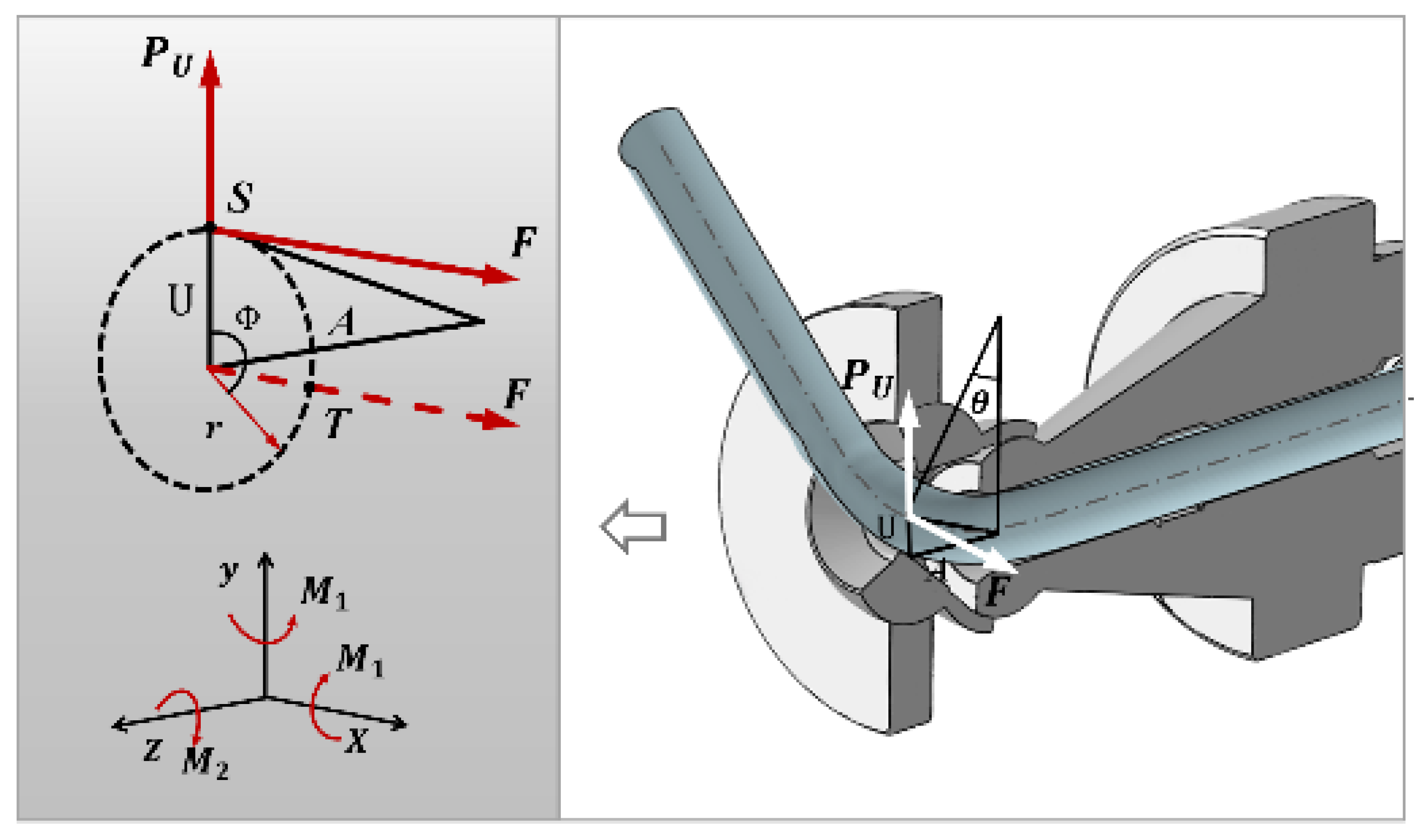
2.1. Principle of Active Deflection

In order to have a deeper understanding of the influence of ADM on the 3D-FBF, it is necessary to analyze in detail the interaction between the forming mechanism and the tube during the active deflection process and the distribution of the stress–strain state inside the bent tube. Meanwhile, the distinctions between the different mold structures used are also analyzed in this section.
If the formed tube faces a risk of collision with the machine, changing the bending direction of the tube is a simple and effective method. As depicted in Figure 1, when pausing the feed movement of the tube, the tube is bent to the target bending radius (R) and angle (θ). The bending die rotates around the equilibrium position (O) to the target position (T) from the current position (S), and the trajectory radius r is equal to the eccentricity (U). By controlling the deflection angle (φ) and eccentricity (U), the formed tube can be deflected to any bending direction to avoid interference phenomenon. Since the curve radius (R) of the tube remains constant during the deflection process, the trajectory of the bending die is uniquely determined by the eccentric distance (U), the deflection angle (φ) and the bending die rotation radius r = U.
The bending die imposes a force F perpendicular to the current bending plane and a force PU parallel to the current bending plane on the tube. At the same time, the contact position between the tube and the guider structure generates the corresponding reaction force due to friction and other factors. The force PU forms the bending moment M1 in the Z–Y plane (Cartesian coordinate system) to maintain the current bending state of the tube. The force (F) and eccentricity (U) form a rotation torque M2 in the X–Y plane, which promotes the tube to rotate around the central axis of the unformed section. Torque M3 formed in the Z–X plane by the force (F) of the bending die on the tube and the length (A) of the bending deformation zone may cause additional bending deformation of the tube in the Z–X plane.
Under ideal conditions, the torque M2 drives the deformed tube to rotate around the axis at a certain angle (φ) so as to gradually deviate from the potential crash location where it interferes with the forming mechanism and achieves the effect of avoiding interference. Since the eccentricity (U) remains unchanged and only transforms the bending direction, the bending quality of the tube is not affected. However, the active deflection in practice tends to cause severe forming defects such as cross-sectional collapse and scratches in the tube and impedes the rotation of the tube.
M 1 = P U R cos θ sin θ
M 2 = F × U
M 3 = F × A

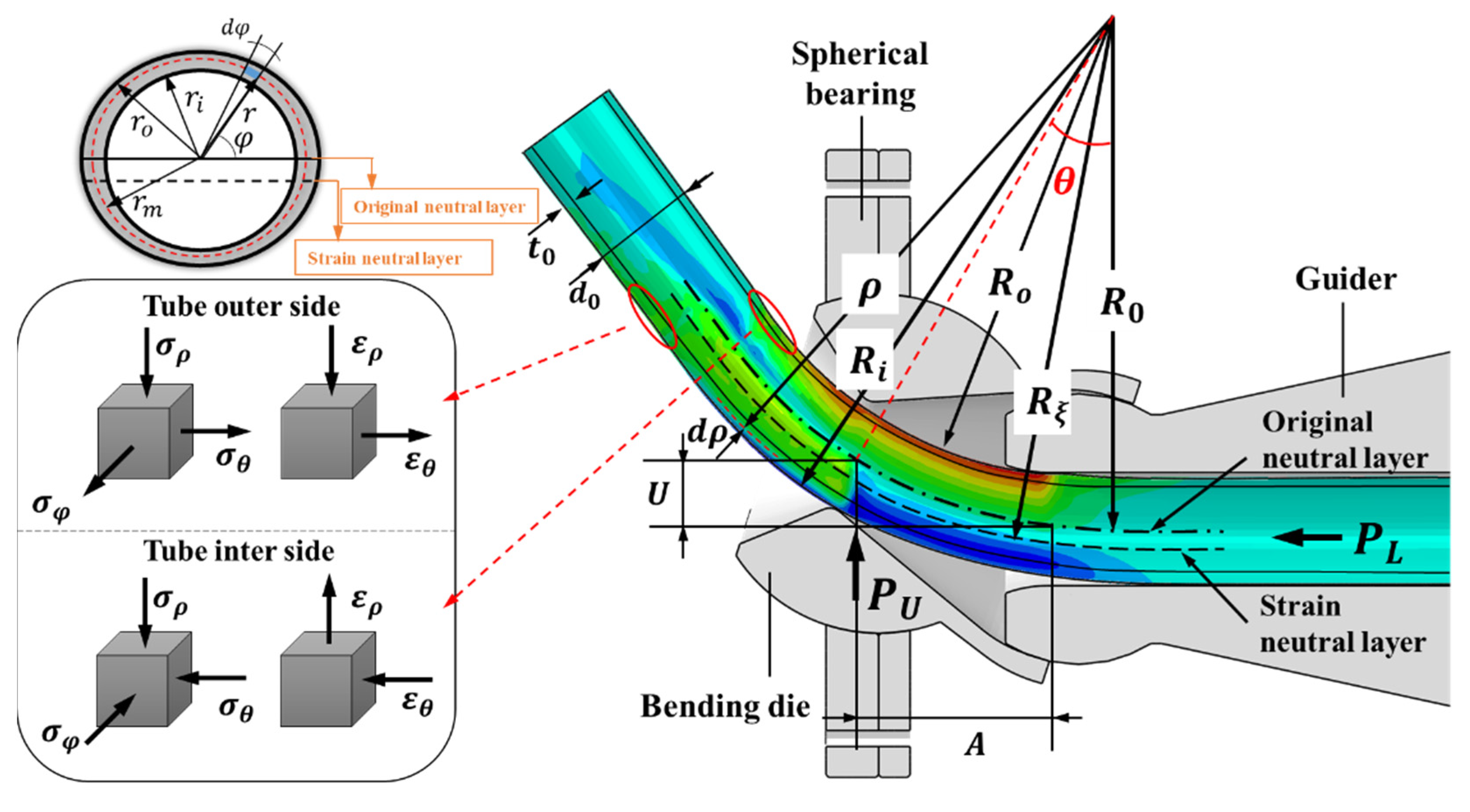
2.2. Theoretical Analysis of 3D Free Bending

Although the tube no longer has noticeable bending deformation in the deflection process, it still shows a tendency to bend deformation. Therefore, it is necessary to analyze the stress–strain state of the hollow metal tube. As shown in Figure 2, to simplify the analysis, the three-dimensional deformation state of the tube was simplified as a plane deformation state, where the tangential strain εθ along the axis direction of the tube, the radial strain ερ along the bending radius and the circumferential strain εφ around the circular direction of the tube are the principal strains. The analysis of the tube’s bending stress and strain state observes the following basic assumptions: (a) the deformed tube is an ideal rigid plastic material; (b) neglecting the flattening distortion caused by circumferential material flow in the cross-section of the tube, ε φ = 0 ; (c) the bend deformation of the tube conforms to a volume incompressible condition [20].
According to the basic assumptions, the plane stress–strain equilibrium equation of the tube can be expressed as
τ θ ρ ρ + 1 ρ σ θ θ + 2 τ ρ θ ρ = 0 σ ρ ρ + 1 ρ τ ρ θ θ + σ ρ σ θ ρ = 0 }
where σ ρ is the radial stress and σ θ is the tangential stress; τ ρ θ , τ θ ρ are the shear stresses of the bending radial and bending tangential planes, respectively. Depending on the distribution law of principal stress and shear stress, τ ρ θ , τ θ ρ are both zero, and the stress equilibrium equation can be simplified as follows
d σ ρ d ρ + σ ρ σ θ ρ = 0
In plane strain state
σ φ = σ θ + σ ρ 2
Therefore, the equivalent stress may be expressed as
σ ¯ = 2 2 [ ( σ ρ σ θ ) 2 + ( σ θ σ φ ) 2 + ( σ φ σ ρ ) 2 ] 1 / 2 = 3 2 | σ θ σ ρ |
Substituting ε φ = 0 into the equivalent strain expression, then
ε ¯ = 3 3 2 ( ε ρ 2 + ε θ 2 + ε φ 2 ) = 3 3 ( 2 | ε θ | )
due to
ε θ = ε ρ = ln ( R + r m sin φ R ζ ) = ln ( ρ R ζ )
The mean of r m is the radius on the cross-section of the tube and R ζ is the radius of the strain neutral layer described in Figure 2. The Hollomon material hardening model formula σ ¯ = k ε ¯ n is introduced into Equations (7)–(9)
| σ θ σ ρ | = 2 3 σ ¯ = ( 2 3 ) 1 + n k | ln ( ρ R ζ ) | n
When ρ R ζ , the bending tube has lateral tangential tension; when ρ < R ζ , the bending tube is compressed tangentially inside. Replacing Equation (10) with stress equilibrium Equation (5) and integrating the two sides of the equation, the inner and outer radial stresses of tube bending can be obtained
σ ρ i = ( 2 3 ) 1 + n [ k 1 + n ] ( ln ( ρ R ζ ) ) 1 + n + C i
σ ρ o = ( 2 3 ) 1 + n [ k 1 + n ] ( ln ( ρ R ζ ) ) 1 + n + C o
where σ ρ i is the internal radial stress, σ ρ o is the lateral radial stress, and Ci and Co are lateral and medial integral constants, respectively, at the inner and outer side surfaces ρ = R 0 r i , ρ = R 0 + r i , in the bending section σ ρ = 0 . Inserting σ ρ = 0 into Equations (11) and (12), then
C i = ( 2 3 ) 1 + n [ k 1 + n ] [ ln ( R 0 r i R ζ ) ] 1 + n
C o = ( 2 3 ) 1 + n [ k 1 + n ] [ ln ( R 0 + r o R ζ ) ] 1 + n
Substituting Equations (13) and (14) with Equations (11) and (12) obtains the distribution of the radial stress of the bending tube, as shown in Equations (15) and (16)
σ ρ i = ( 2 3 ) 1 + n [ k 1 + n ] [ ln ( ρ R ζ ) ] 1 + n ( 2 3 ) 1 + n [ k 1 + n ] [ ln ( R 0 r i R ζ ) ] 1 + n
σ ρ o = ( 2 3 ) 1 + n [ k 1 + n ] [ ln ( ρ R ζ ) ] 1 + n ( 2 3 ) 1 + n [ k 1 + n ] [ ln ( R 0 + r o R ζ ) ] 1 + n

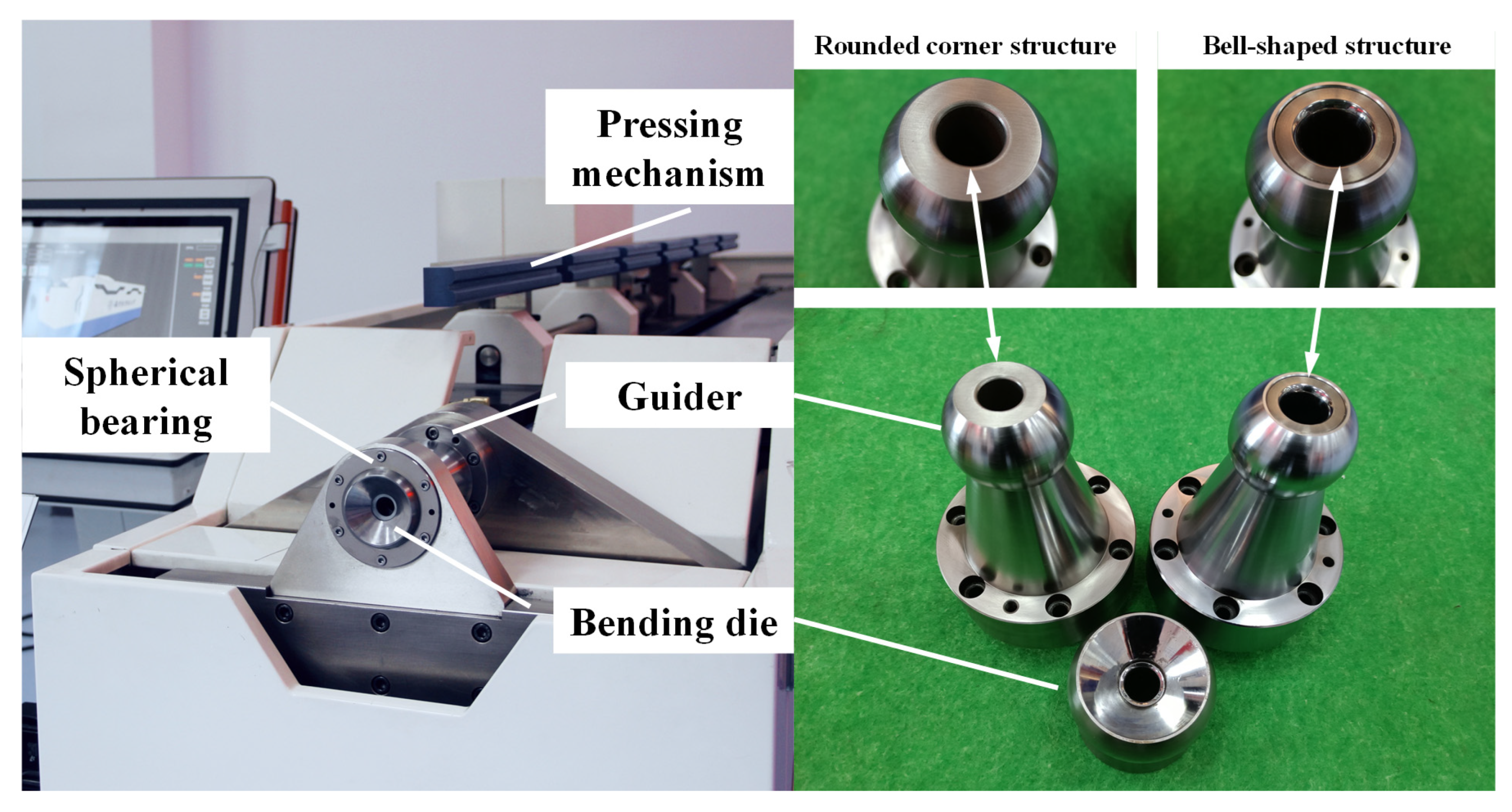
2.3. Mold Structure Design

In the bending process, the tube is pushed out from the guide mechanism and deformed under the action of the bending die. Since the front end of the guider is the initial position of the tube bending deformation, its structural design directly affects the stress state of the deformed tube. The two kinds of structure are used to optimize the stress state in the contact area between the tube and the guider in Figure 3. The front end of the first transition structure is connected directly through a common fillet of R = 1 mm, which is the widest application form at present. Another transition structure is a bell-shaped surface with the maximum curvature radius R = 18.22 mm so that the main contact position of the tube and the guide structure is as smooth as possible. To ensure the reliability of the test results, the structural parameters of other parts of the mold remain uniform, and the specific parameter design is shown in Table 1.

3. Simulation of 3D Free Bending Active Deflection to Avoid Interference

To more accurately reflect the deformation of the tube, this section primarily investigates the active deflection process with both simulation and experimental phases. The mechanical property of the stainless steel (SUS304) tube was obtained by uniaxial tensile tests. Then, the reliability of the finite element model was verified based on the simulation and test comparison under different trajectory radius conditions.

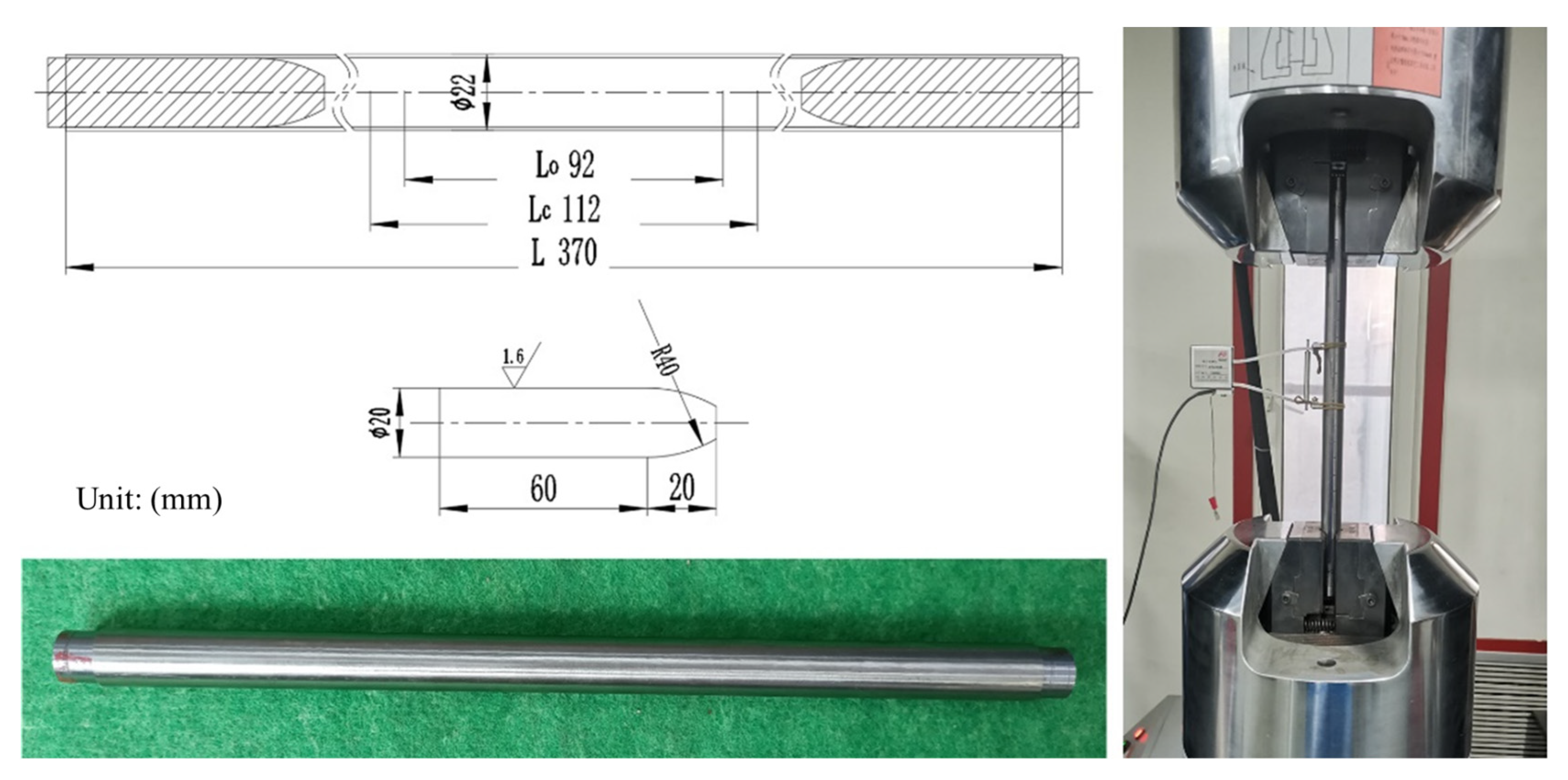
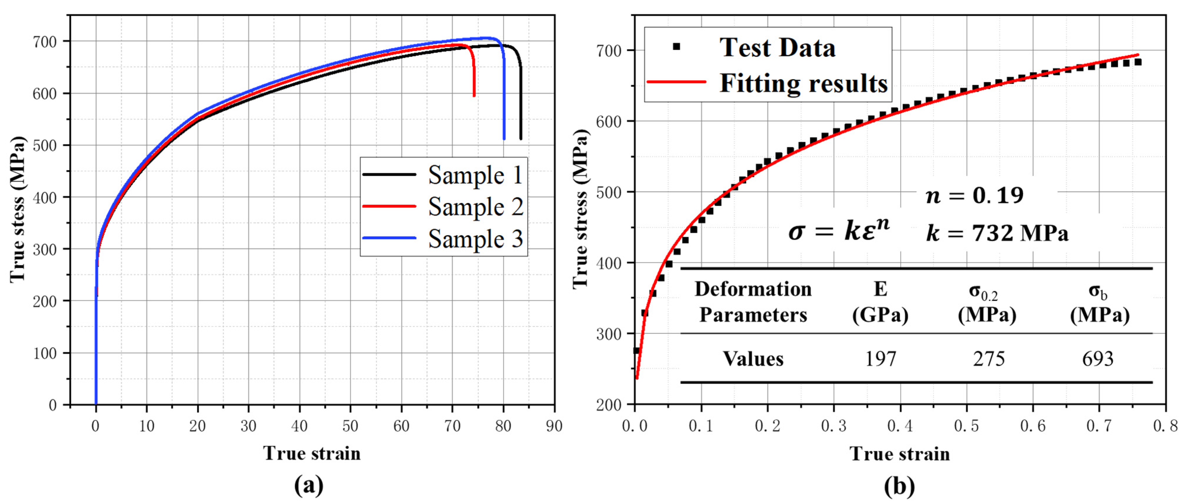
3.1. Mechanical Characterization

The mechanical properties of the material such as the elastic modulus and yield strength are important factors affecting the deformability of the material and the bending limit of the tube under less constrained conditions. The SUS304 stainless steel tube, with wide application and good ductility, was used for simulation modelling and active deflection experiments in this paper. As shown in Figure 4, the diameter of the tube was d0 = 22 mm and the thickness t0 = 1 mm. The chemical composition of SUS304 stainless steel is presented in Table 2.
The uniaxial tensile test was performed at room temperature according to the HB 5145-1996 standard. For a small size tube less than 30 mm in diameter, the whole tube tensile specimen was used to reduce the test error. The true stress–strain curves of the tensile samples in the elastic phase coincided exactly, as shown in Figure 5a, and there were only minor errors in the strengthening phase, which indicates that this tensile data have sufficient reliability. The material model of the SUS304 stainless steel tube based on the Hollomon hardening model was obtained by processing the tensile data of sample 3 depicted in Figure 5b.

3.2. Finite Element Modelling

As depicted in Figure 6, a finite element model was established to study the influence of the deflection avoidance process on the forming of the tubes, and the simulations were carried out under different trajectory radii and different guider structures. The FEM mainly included the bending die, spherical bearing, guider, tube, pressing mechanism, propulsion device and other components. The bending die, guide structure and other mold parts without deformation were set to a rigid entity type, and the grid type was selected as the C3D10M format [21]. The tube blank was defined as a shell type with five integral nodes and the S4R format was selected for the mesh type [22]. The mid surface of the tube was used for modeling, allowing the extraction of data such as stress–strain, location coordinates and wall thickness. The 3D-FBF mechanism and the contact relationship between the tube blank made a setting for the general contact. According to Coulomb’s theory, the friction coefficient between the tool and the tube was described as 0.05 [23]. The mass scaling factor was set to 1000, and the target time increment was adopted to obtain a more stable bending condition and sufficient computational efficiency concurrently for the dynamic effect of the ABAQUS/Explicit module. The specific motion parameters of the finite element model are shown in Table 3 [12,24,25].

3.3. Comparison of Theoretical and Experimental Results of Free Bending

Figure 7 and Figure 8 show the numerical simulations and experiments (U = 12 mm) to investigate the effect of the active deflection processes on the tube. The radial stresses at the primary deformation zone (S11, the normal stress in X, Unit: MPa) were compressed inside and outside of the bending section, which is consistent with the theoretical analysis of Equations (15) and (16). The deflection angle of the finite element simulation was φ = 78.60° and the actual deflection angle was φ = 43.64°. Moreover, elliptical distortions were produced in the cross-section at the location where the tube was in contact with the guide structure. The actual cross-section distortion at the contact position before deflection was Δ = 7.23%, as illustrated in Figure 7, while the finite element simulation was 8.40%, with an error of 16.18%.
During the deflection process, the amplitude of the radial stress increased, and resulted in a large radial deformation of the tube. In Figure 9, the cross-sectional shape was redistributed during the deflection process, and the wall of the tube on the deflected side produced severe concavity and upward convexity, which was referred to as a goose-head defect, as depicted in Figure 8, whereas for M3 and the friction resistance in Equation (3), defects such as the additional bending and the torsion were also generated during active deflection. The simulation showed that the finite element model developed in this paper had sufficient accuracy in predicting the bending deformation state and active deflection defects of the tubes.

4. Discussion

The tube deflection angle and section profile are the main factors affecting the forming accuracy and working ability, making this paper adopt the section distortion rate and deflection angle as the main indexes to evaluate the active deflection performance. Previous theoretical analyses have shown that the radius of the eccentricity of the bending die determines the active deflection torque and that different designs of the die structure can change the distribution of the stress state. Therefore, the simulation experiment of active deflection was carried out based on the five groups of eccentricity (U = 6 mm, 8 mm, 10 mm, 12 mm, 14 mm), rounded corners and bell-shaped transition forms of the guider in this paper. The influence of eccentricity (or trajectory radius) and the transition structure of the guider on the deflection quality was analyzed as follows.

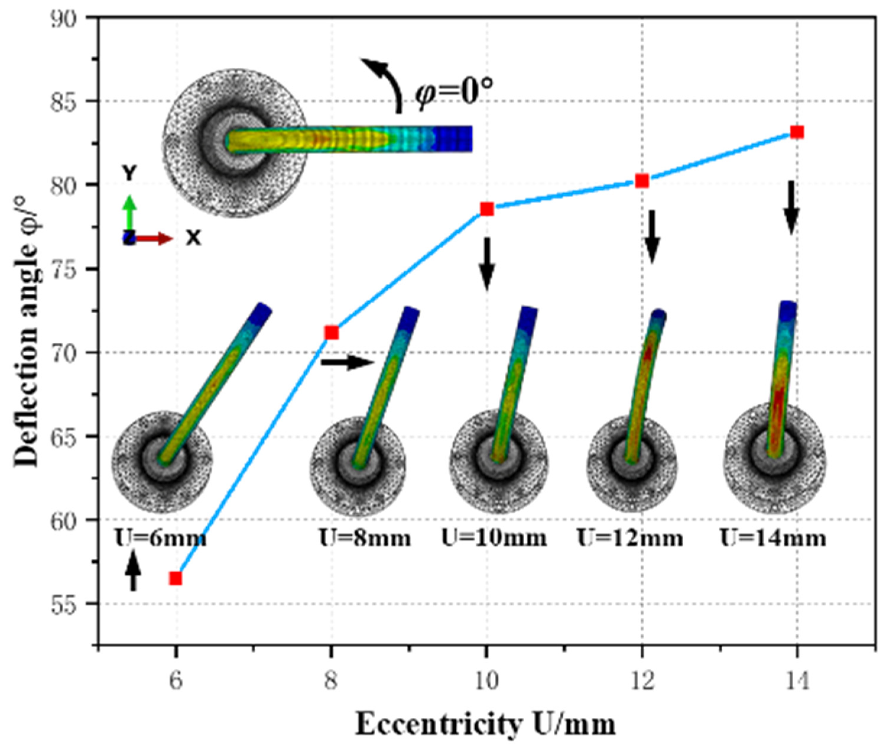
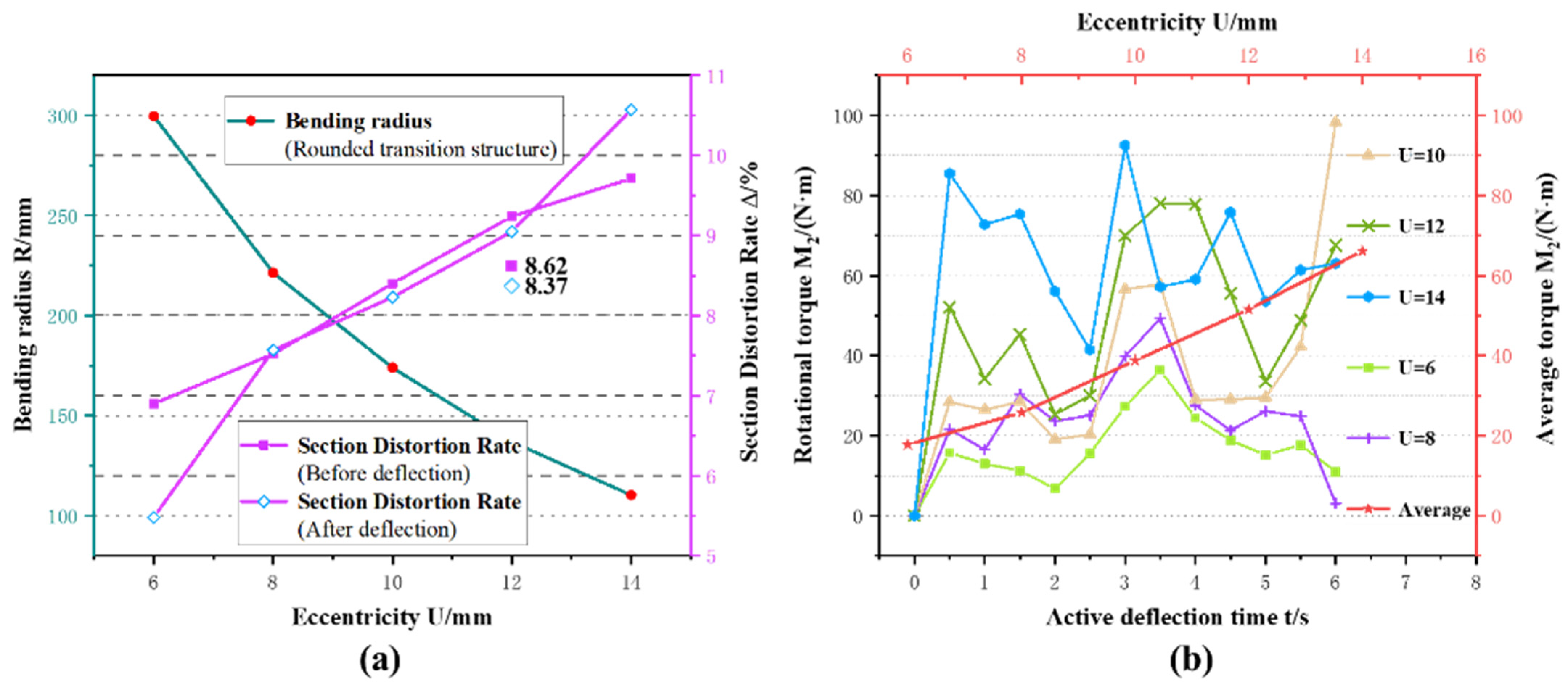
4.1. Effect of Eccentricity on the Active Deflection Method

The active deflection simulation experiment was implemented in the rounded corner transition guider and with U = 6, 8, 10, 12 and 14 mm (eccentricity) to study the influence of eccentricity on the active deflection effect. The independent variables are consistent with Table 2. Figure 10 and Figure 11 show that both the deflection angle and section distortion rate increase with the enlargement of the eccentricity. When U = 14 mm, the deflection angle φ = 83.00°, and the section distortion Δ = 9.71%. By extracting the reaction force on the guider according to Equation (2), the distribution of the torque exerted by the bending die on the tube during active deflection can be calculated, as shown in Figure 11b. According to the rotational moment curve, the rotating torque expanded with the gradual expansion of the eccentric distance. Therefore, the larger angular deflection of the tube could be produced with the movement of the bending die and the accuracy of the active deflection angle also improved simultaneously with the increase in the torque. Moreover, the active deflection angle was more sensitive to changes in eccentricity because the bending die could not exert sufficient driving force on the tube when the eccentricity was small.
The variation in cross-section distortion with eccentricity is depicted in Figure 11a. In general, the cross-section distortion rate front–back of the deflection increased with the eccentricity. When U = 14, the cross-section distortion rate reached the maximum values of 9.71% and 10.57%, respectively. The transverse section aberration rate had a small increase after deflection and only slightly expanded at U = 6 mm and U = 14 mm, reaching 1.42%. The main reason is that before the active deflection, the bending radius decreases gradually with higher eccentricity, and the degree of bending keeps deepening. The radial stress amplitude grows with the deepening of the bending degree, which enhances the radial deformation of the tube wall and intensifies the deformation of the section. As the deflection only changes the tube direction and not the bending radius, the active deflection process has a small effect on the distortion extent of the tube cross-section and only causes redistribution of the section shape. Nevertheless, since the hindering effect of the tube segment deformation increases with eccentricity, the target deflection angle cannot be achieved even when deflection is performed at a larger eccentricity. This phenomenon explains why the growth rate of the deflection angle slows down with the expansion of eccentricity. Therefore, the eccentricity (or trajectory radius) of the bending die is the majority factor in determining the deflection angle, with other conditions remaining constant.

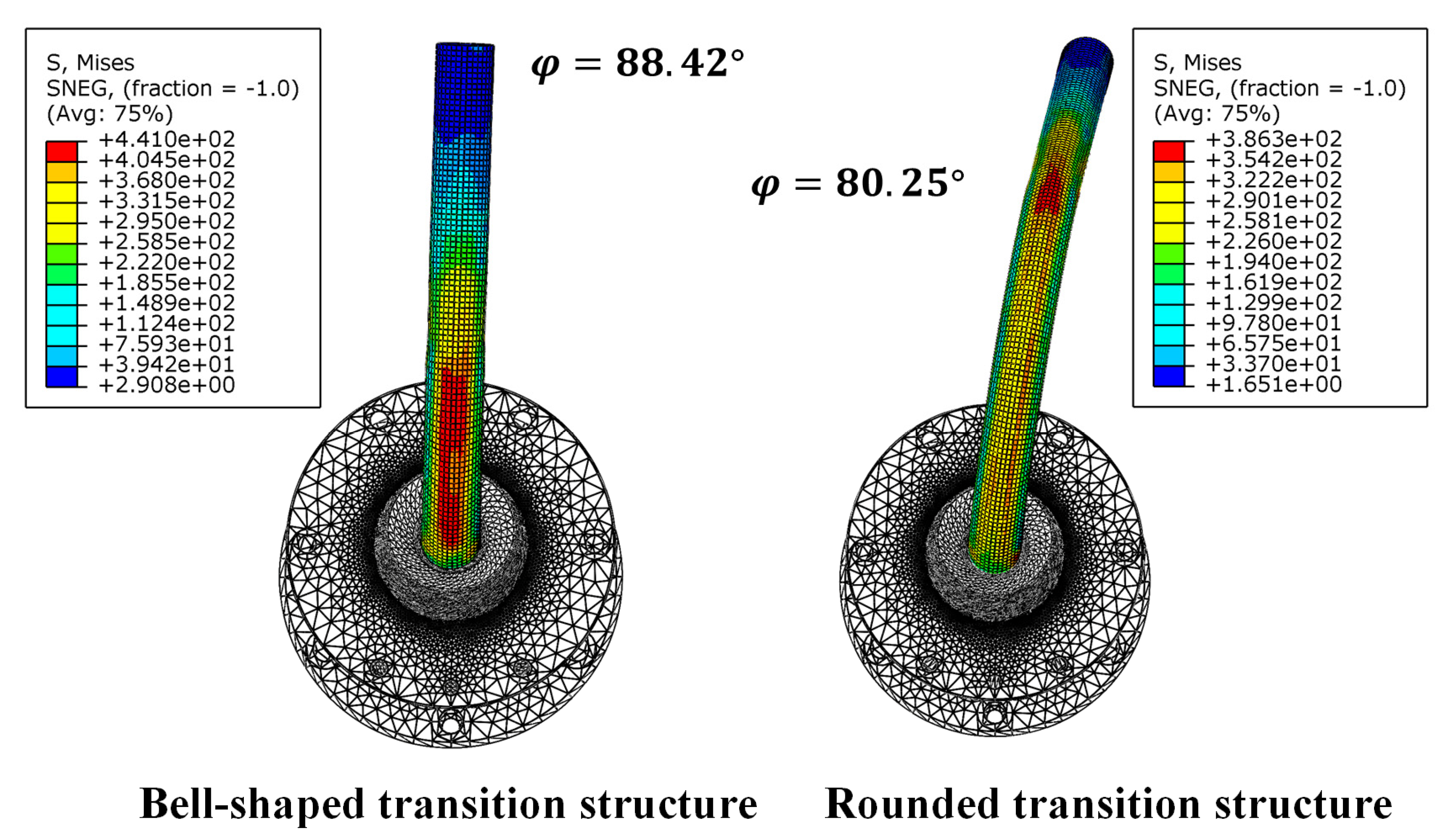
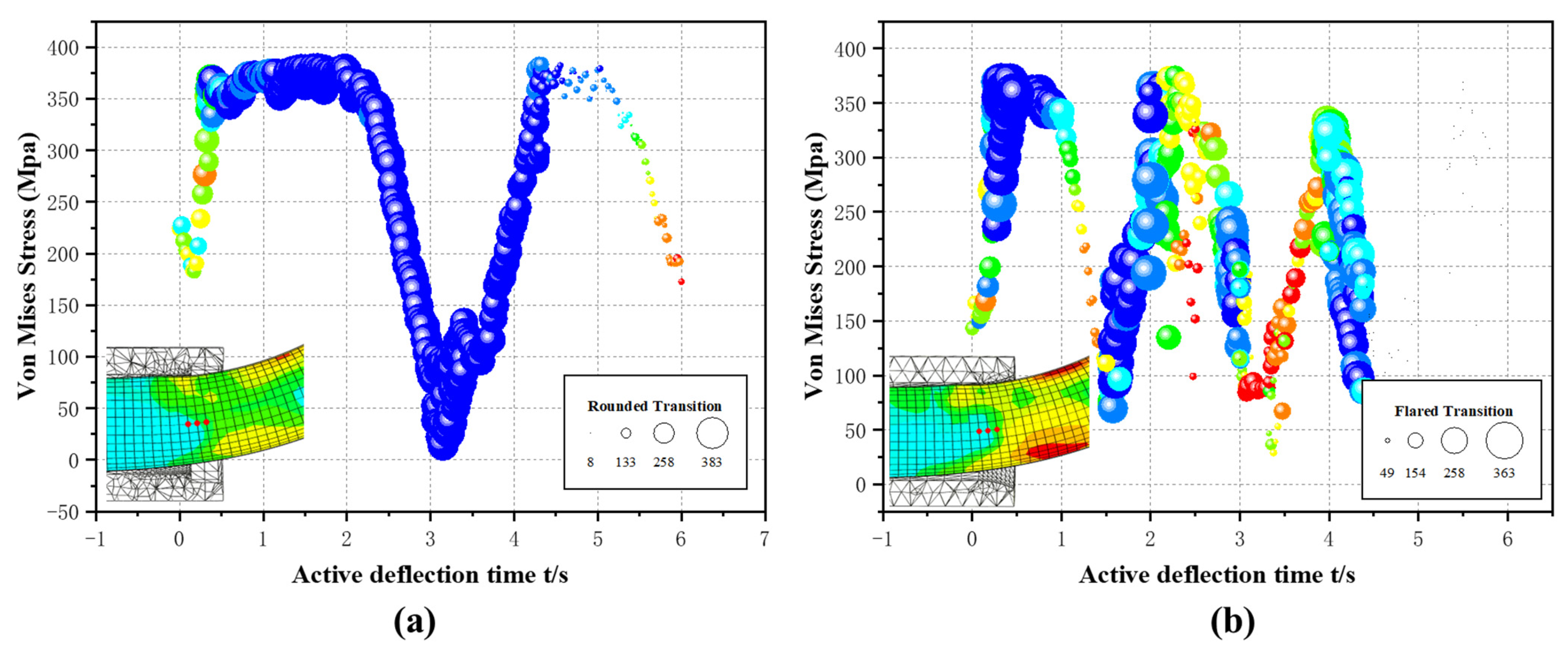
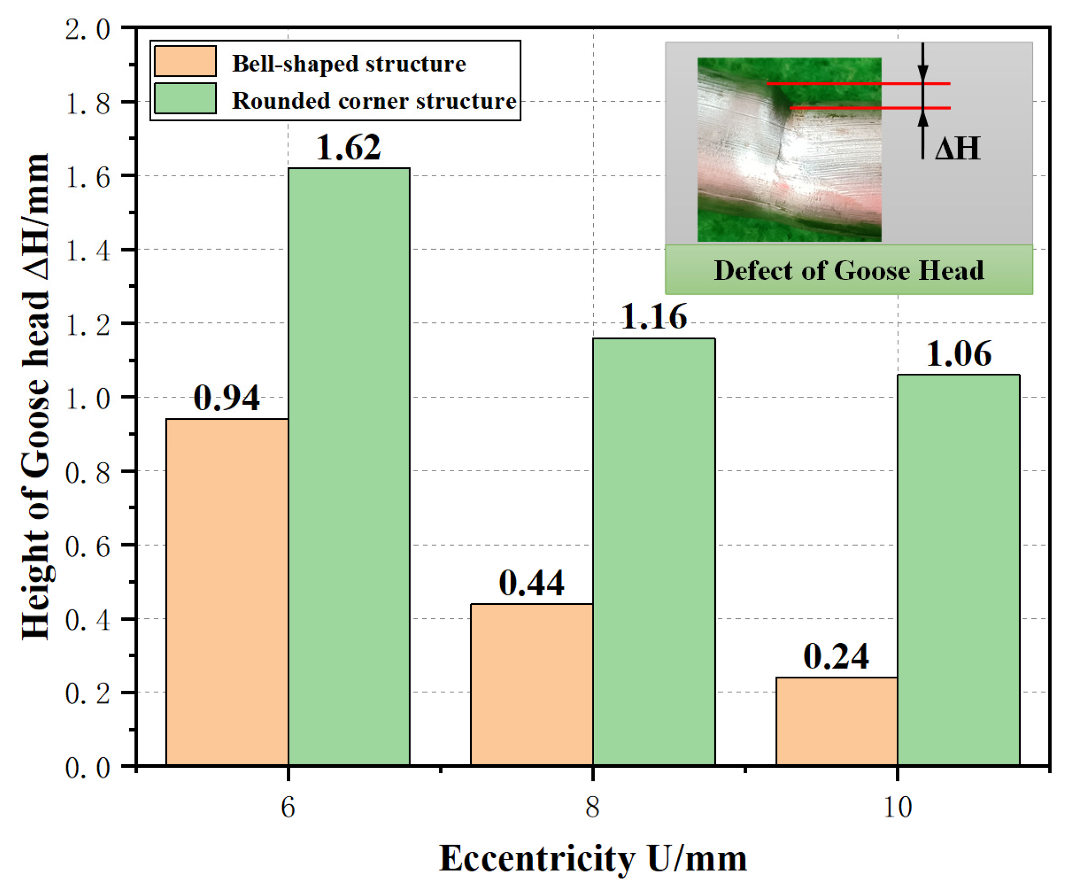
4.2. Effect of Transition Structure on Active Deflection Method

In accordance with the research on the formation of section distortion in Section 3.3, radial stress and stress concentration are among the main reasons for section distortion. Although radial stresses are primarily determined by the degree of tube bending, the uniformity of stress distribution can still have an important effect on section deformation. To study the influence of the front transition structure of the guider on the active deflection, the comparative simulation of the common fillet transition structure and the bell-shaped transition structure were developed. Experimental eccentricity was U = 12 mm, and mold structure parameters were as shown in Table 1.
As shown in Figure 12, the active deflection angle with the rounded transition structure φ = 80.25°. With the bell-shaped transition structure, the active deflection angle reached 88.42°, which was only 1.58° different than the target deflection angle. In addition, the cross-section distortion rate of the tubes with a bell-shaped transition structure was also lower than that of the ordinary fillet transition structure as depicted in Figure 11a. To characterize the influence of different transition structures on the stress concentration, the Von Mises stress distribution of the tube integration node during the location of contact with the transition structure was extracted, respectively, as depicted in Figure 13. A synthesis of the Von Mises stress data was performed to eliminate the influence of fluctuation effects on the results.
The research found that the peak Von Mises stresses for active deflection simulations with different transition structures were almost the same, about 375 MPa (>σs). This shows that the maximum stress in the tube mainly depends on the chosen material and the bending state. However, when the rounded transition structure was used for deflection, the tube remained in a high stress state for a longer period compared to the bell-shaped transition structure. As mentioned above, the higher stress state is one of the principal factors causing excessive distortion of the cross-section. It disrupted the radial force balance achieved in the bending phase of the tube and resulted in further local collapse by causing radial stresses in the local cross-section to exceed the material yield strength. Therefore, during the actual forming process, the higher stress concentration further enhanced the friction between the tube and the mold and caused more severe defects such as section deformation, goose-head and surface scratches.
The stress values showed a fluctuating trend similar to a sinusoidal function when the bell-shaped transition structure was used, as shown in Figure 13b. However, the overall distribution of the Von Mises stress state was more uniform and, in particular, the residence time in the high stress range was shorter compared to the active deflection process with the rounded corner transition structure. As a result, the tube interacted more gently with the front of the guider during the active deflection and the stress was more evenly distributed. The intermittent stress distribution also allowed for a smooth redistribution process of the tube cross-section. Meanwhile, the cross-sectional deformation was reduced to a much lesser extent and had fewer effects on the rotation of the tube. Therefore, the bell-shaped transition structure allowed for a larger rotation angle.

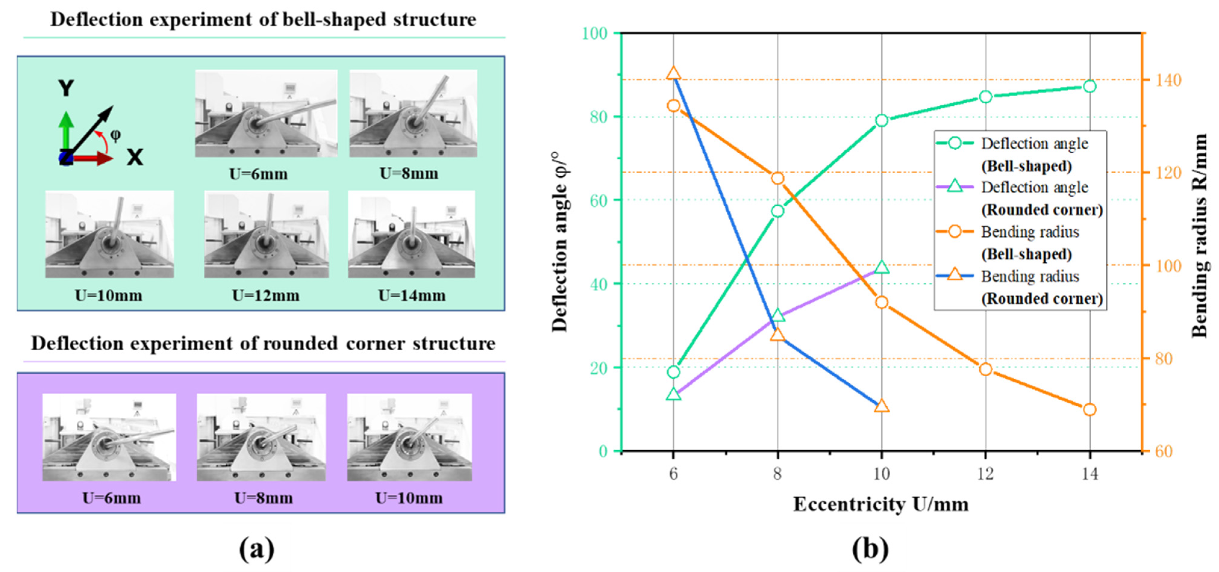
4.3. Experiment of Active Deflection

To verify the results of the theoretical analysis and simulation, active deflection experiments were conducted with the same process parameters. As shown in Figure 14, the active deflection experiment was implemented by three-axis free bending forming equipment (NUAA-G30: designed and manufactured by Nanjing University of Aeronautics and Astronautics, Nanjing, China). The bending forming and active deflection experiments under different transition structure conditions were carried out by replacing the guide structure. With the exception of this, the other forming mechanisms maintained full consistency.
The experimental results of active deflection using the rounded corner and the bell-shaped transition structure are illustrated, respectively, in Figure 15. When U = 10 mm, the tube was close to the bending limit owing to the ordinary fillet transition structure. When the eccentric distance (U) was greater than 10 mm, the use of an ordinary rounded transition structure for bending made the tube exceed the bending limit and an instability phenomenon happened. Therefore, the active deflection experiment was only performed under the eccentricity values U = 6, 8 and 10 mm. As shown in Figure 16, the ultimate deflection angle of the rounded transition structure was only 43.64°, while the ultimate deflection angle of the bell-shaped transition structure reached 87.23°, far greater than the former.
The active deflection with the fillet transition structure produced a more severe section distortion, and the position of the distortion corresponded to the location of the stress concentration in the simulation as depicted in Figure 15. This phenomenon proves that the local stress concentration is the major factor inducing the section distortion, affecting the section shape redistribution and further hindering the active deflection process. As shown in Figure 17, due to the curvature of the bell-shaped transition being more similar to the curvature of the tube and the larger contact area with the tube, the stresses were distributed more evenly, which had little effect on the redistribution process of cross-section distortion. In the case of small eccentricity, only a slight goose-head phenomenon was formed, which had a weak hindering effect on the deflection process, and therefore a large deflection angle was obtained.
The cross-section distortion maintains the same positive correlation trend with the eccentricity before and after the deflection, as shown in Figure 18 for the active deflection experiment by adopting the bell-shaped transition structure. It further proved that the value of the cross-section distortion was mainly determined by the bending degree of the tube. Compared with the rounded transition structure in Figure 15a, the goose-head phenomenon was apparent only at small eccentricities, as shown in Figure 15b when the bell-shaped transition structure was employed. The small eccentric distance did not provide enough deflection torque to drive the pipe through large angles; hence the work performed by the bending die on the pipe was consumed by additional bending. However, the goose-head phenomenon still disappeared gradually as the eccentricity increased as shown in Figure 17. Due to the expanding deflection moment, active deflection of the tube was more easily achieved. Simultaneously, stress concentrations continuously moved along the circumferential direction of the tube in deflection and were uniformly distributed throughout the cross-section, thus reducing severe deformation of the cross-section.
In addition, the deviation of the cross-sectional distortion rate gradually grew larger in the experiment as shown in Figure 16, which was different from the simulation shown in Figure 11a. The isotropic material model that ignored the effect of material inhomogeneity on plastic deformation and the dynamic simulation error were the major reasons for the large deviation between the simulation and experimental results. Therefore, the established finite element model only reflected the change in section distortion values but could not accurately predict the redistribution of section morphology and the development of section morphology to a goose-head shape. Goose-head is a more violent form of material flow during the actual forming process. When the goose-head phenomenon develops to a certain extent, it will create destructive damage to the tubes. As a result, the friction between the damaged tube and the mold became even more intense, and the resulting mechanical resistance was more severe than the ovalization distortion.

5. Conclusions

A method for actively deflecting the tube was proposed to achieve interference avoidance by controlling the motion of the bending die. Theoretical analysis and experiments investigated the active deflection principle and the effect on free bending forming. The results are as follows:
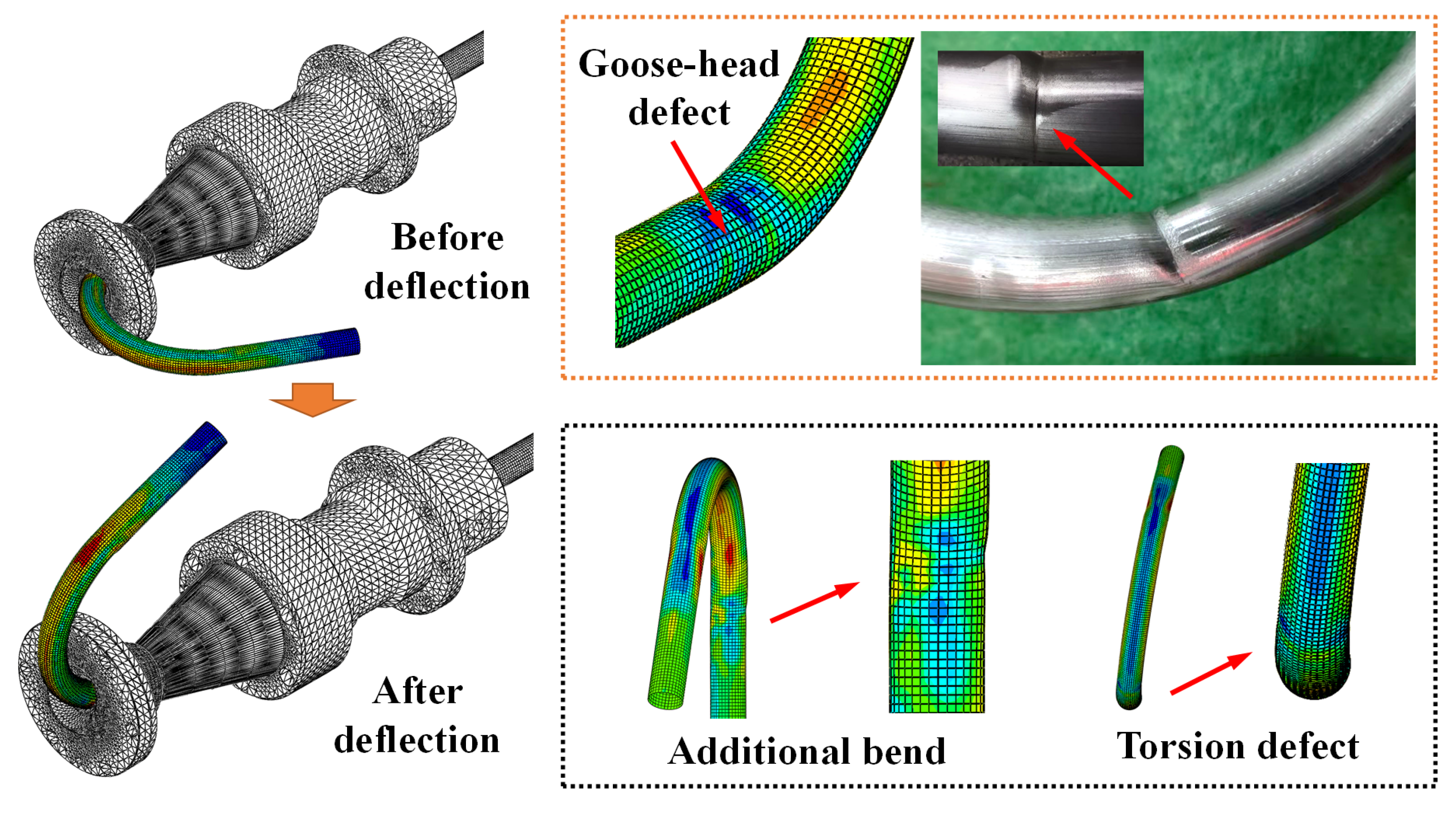
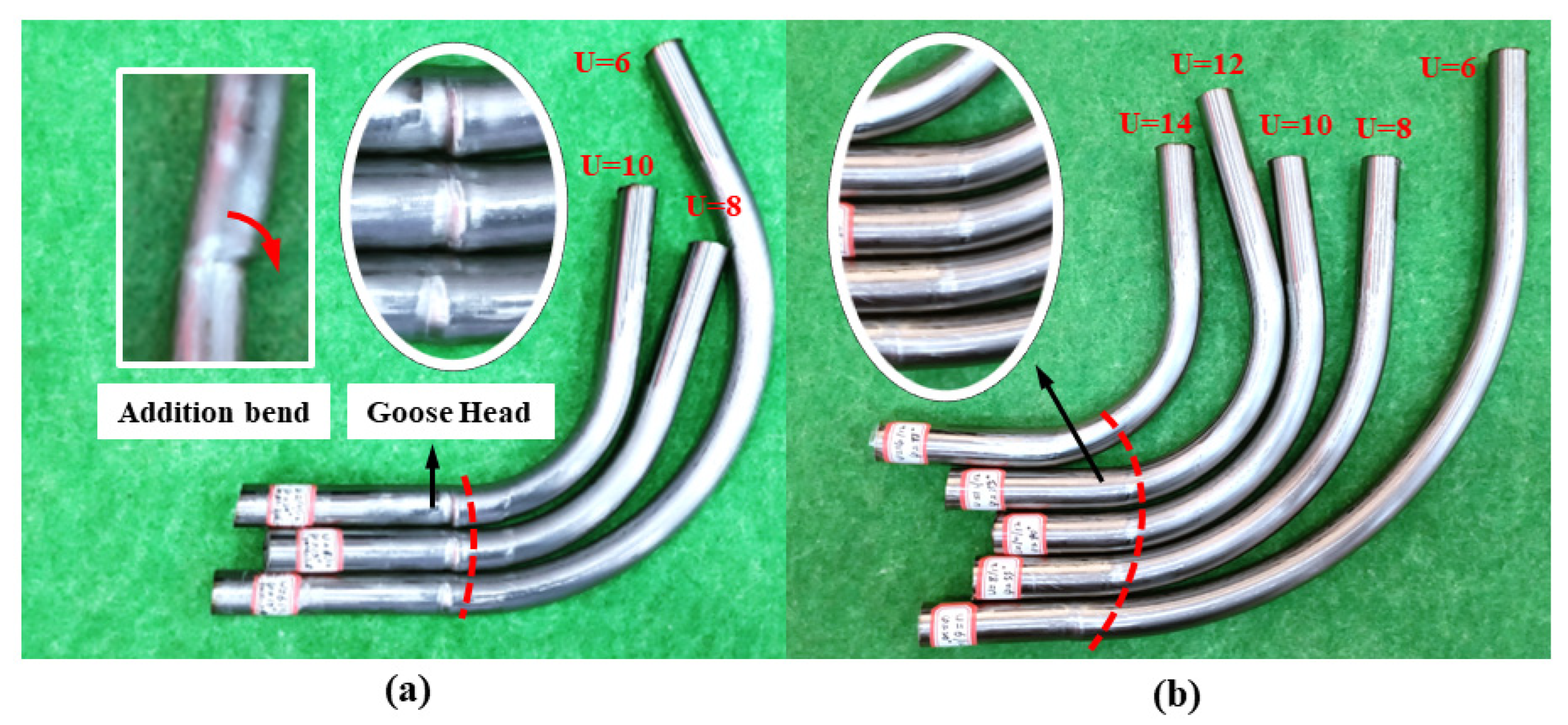
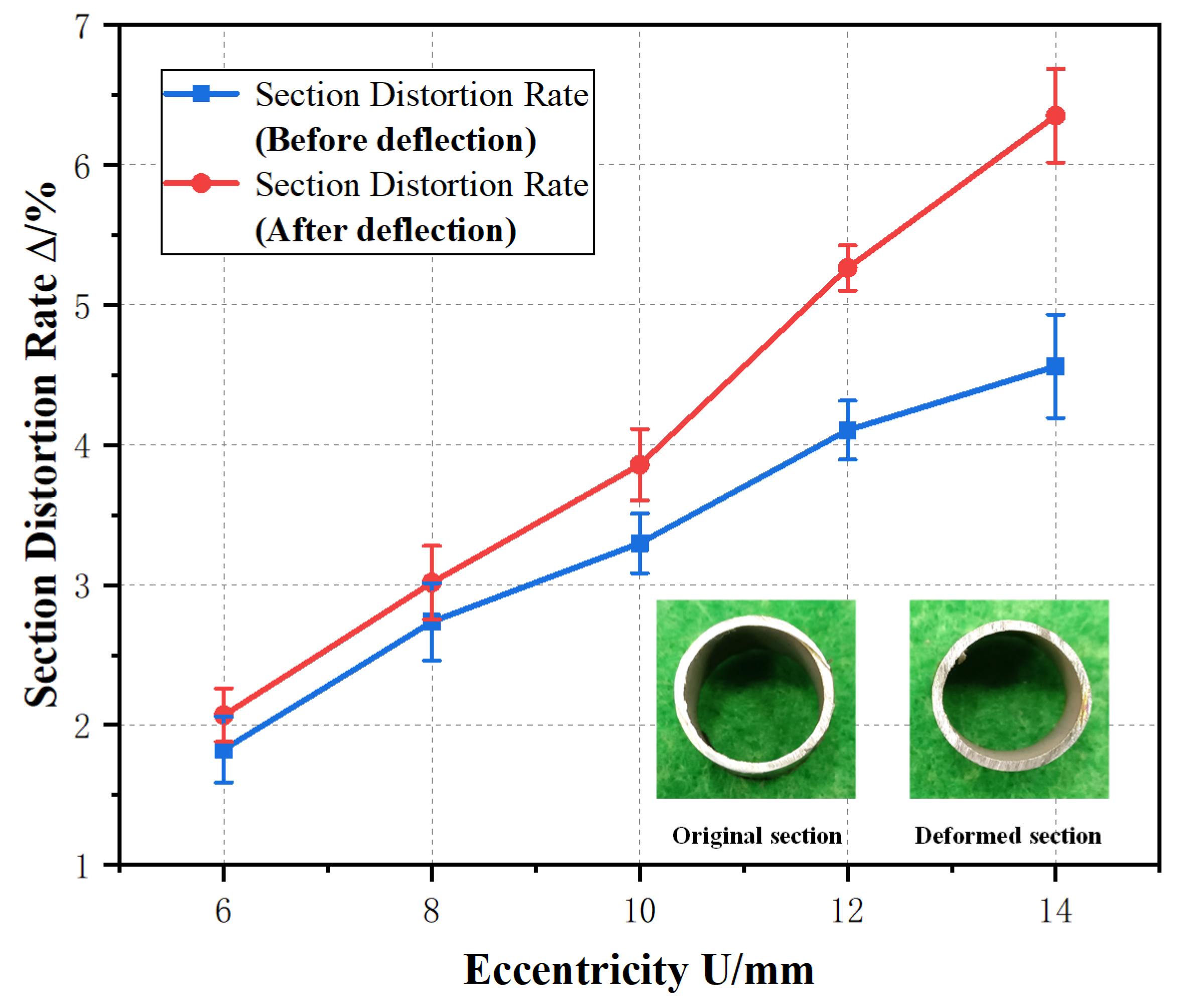
  • The active deflection method led to the redistribution of the tube’s section distortion, and the stress concentration exacerbated the section distortion degree and even caused more serious forming defects such as goose-head. In addition, the greater deviation of the angle is one of the primary problems of the active deflection method.
  • The active deflection angle has been found to rise with the growth of the trajectory radius. A greater deflection angle could be obtained with a small bending radius due to the enlargement of the torque with an increasing trajectory radius. The maximum deflection angle reached 87.23° under the experimental environment presented in this paper. Yet the maximum deflection angle with the rounded transition structure failed to reach the target angle, φ = 90°.
  • The bell-shaped transition structure provided a larger support area for the deformed tube and allowed for a more uniform stress distribution between the tube and guide contact position. As a result, the distortion rate of the cross-section was reduced by 7.31 percent under the same conditions and severe section distortions such as goose-head were essentially eliminated.

Author Contributions

Conceptualization, H.Z. and X.G.; methodology, C.C.; formal analysis, X.G.; investigation, H.Z.; resources, C.C.; data curation, H.Z.; writing—original draft preparation, H.Z.; writing—review and editing, H.Z., A.A.E.-A., S.Z. and other authors together; supervision, J.T.; project administration, C.C.; funding acquisition, C.C. All authors have read and agreed to the published version of the manuscript.

Funding

This research was funded by the National Natural Science Foundation of China (Nos: U1937206, 52175328, 52105360, 5201101342), the Opening Project of State Key Lab of Digital Manufacturing Equipment & Technology (No. DMETKF2021004), the Jiangsu Province Key Research and Development Project (No. BE2019007-2), the Fundamental Research Funds for the Central Universities (No. NS2022061), the Open Fund of Jiangsu Industrial Perception and Intelligent Manufacturing Equipment Engineering Research Center (No: 2021-04), 2021 Jiangsu Shuangchuang Talent Program (No. JSSCBS20210157), Jiangsu Province Science and Technology Project (No. BK20200453), Ningbo “science and technology innovation 2025” major special project (No. 2020Z078) and the Nanjing University of Aeronautics and Astronautics graduate research and practice innovation program (No. xcxjh20210610).

Data Availability Statement

In the current publication, all data are contained in the paper either as numbers or in graphical form.

Acknowledgments

The authors are also grateful for the support from Flexible Forming Laboratory in Nanjing University of Aeronautics and Astronautics in this research. The authors would like to thank Yangtze Delta Region Institute of Advanced Materials for its assistance with material properties’ testing.

Conflicts of Interest

The authors declare no conflict of interest. The funders had no role in the design of the study; in the collection, analyses, or interpretation of data; in the writing of the manuscript; or in the decision to publish the results.

Nomenclature

φdeflection anglerbending die rotation radius
PLaxial thrust of tube r m radius of cross-section
PUforce of bending die thrustRtheoretical bending radius
Ueccentricity R ζ radius of the strain neutral layer
Adeformation zone length ρ bending radius
M1, M2, M3bending moment ρ 0 outer bending radius
τ ρ θ ,   τ θ ρ shear stress ρ i inter bending radius
σ ¯ ,   ε ¯ equivalent stress\stress C i ,   C i integral constants
σ ρ 0 lateral radial stressΔcross-section distortion rate
σ ρ i internal radial stress
ε r ,   ε θ ,   ε φ radius\tangential\circumferential strain
σ r ,   σ θ ,   σ φ radius\tangential\circumferential stress

References

  1. Ma, J.; Li, H.; Fu, M. Modelling of Springback in Tube Bending: A Generalized Analytical Approach. Int. J. Mech. Sci. 2021, 204, 106516. [Google Scholar] [CrossRef]
  2. Ahn, K.; Lee, K.-H.; Lee, J.-S.; Won, C.; Yoon, J. Analytic springback prediction in cylindrical tube bending for helical tube steam generator. Nucl. Eng. Technol. 2020, 52, 2100–2106. [Google Scholar] [CrossRef]
  3. Huang, T.; Wang, K.; Zhan, M.; Guo, J.; Chen, X.; Chen, F.; Song, K. Wall Thinning Characteristics of Ti-3Al-2.5V Tube in Numerical Control Bending Process. J. Shanghai Jiaotong Univ. 2019, 24, 647–653. [Google Scholar] [CrossRef]
  4. Goto, H.; Tanaka, Y.; Ichiryu, K. 3D. Tube Forming and Applications of a New Bending Machine with Hydraulic Parallel Kinematics. Int. J. Autom. Technol. 2013, 49, 92–98. [Google Scholar] [CrossRef]
  5. Tao, J.; Xiong, H.; Wan, B. 3D Free-bending Forming Equipment and Key Technology. Precis. Form. Eng. 2018, 4, 1–13. [Google Scholar] [CrossRef]
  6. Chen, H.; Wang, H.; El-Aty, A.A.; Qin, Y.; Li, J.; Zhang, Y.; Li, T.; Guo, X. Impact of bending dies with different friction forms on forming force and quality of tubes manufactured by free bending technology. Chin. J. Aeronaut. 2021, 34, 253–264. [Google Scholar] [CrossRef]
  7. Li, Y.; Li, A.; Yue, Z.; Qiu, L.; Badreddine, H.; Gao, J.; Wang, Y. Springback prediction of AL6061 pipe in free bending process based on finite element and analytic methods. Int. J. Adv. Manuf. Technol. 2020, 109, 1789–1799. [Google Scholar] [CrossRef]
  8. Zhao, F.; He, W.P.; Qin, Z.; Zhang, W. Knowledge-based search Algorithm for Tube Bending Interference Avoidance. Appl. Res. Comput. 2006, 11, 65–67. [Google Scholar] [CrossRef]
  9. Hermes, M.; Staupendahl, D.; Becker, C.; Tekkaya, A.E. Innovative Machine Concepts for 3D Bending of Tubes and Profiles. Key Eng. Mater. 2011, 473, 37–42. [Google Scholar] [CrossRef]
  10. Li, T.; Wang, H.; El-Aty, A.A.; Li, J.; Zhang, Y.; Wei, W.; Chen, H.; Cheng, X.; Tao, J.; Guo, X. Theoretical modelling and finite element simulation of AA6061 involute components based on 3D free bending process. Int. J. Mech. Sci. 2020, 178, 105607. [Google Scholar] [CrossRef]
  11. Yang, H.; Li, H.; Ma, J.; Li, G.; Huang, D. Breaking bending limit of difficult-to-form titanium tubes by differential heating-based reconstruction of neutral layer shifting. Int. J. Mach. Tools Manuf. 2021, 166, 103742. [Google Scholar] [CrossRef]
  12. Tao, H.; Fangfang, Y.; Mei, Z.; Junqing, G.; Xuewen, C.; Fuxiao, C.; Kexing, S. Section Flattening in Numerical Control Bending Process of TA18 High Strength Tube. Rare Met. Mater. Eng. 2021, 47, 2347–2352. [Google Scholar] [CrossRef]
  13. Chiew, S.P.; Jin, Y.F.; Lee, C.K. Residual stress distribution of roller bending of steel rectangular structural hollow sections—ScienceDirect. J. Constr. Steel Res. 2016, 119, 85–97. [Google Scholar] [CrossRef]
  14. Maier, D.; Stebner, S.; Ismail, A.; Dölz, M.; Lohmann, B.; Münstermann, S.; Volk, W. The influence of freeform bending process parameters on residual stresses for steel tubes. Adv. Ind. Manuf. Eng. 2021, 2, 100047. [Google Scholar] [CrossRef]
  15. Ma, J.; Welo, T.; Wan, D. The impact of thermo-mechanical processing routes on product quality in integrated aluminium tube bending process. J. Manuf. Process. 2021, 67, 503–512. [Google Scholar] [CrossRef]
  16. Ismail, A.; Maier, D.; Stebner, S.; Volk, W.; Münstermann, S.; Lohmann, B. A Structure for the Control of Geometry and Properties of a Freeform Bending Process. IFAC 2021, 54, 115–120. [Google Scholar] [CrossRef]
  17. Guo, Y. Research on Technology of Programming and Simulation of NC Tube Bending; Beijing Institute of Technology: Beijing, China, 2011; Available online: https://go.exlibris.link/mbqwBwvg (accessed on 1 June 2011).
  18. Gao, Z. Research on Key Technologies of Tube Digital Integrated Manufacturing; Beijing Institute of Technology: Beijing, China, 2011; Available online: https://go.exlibris.link/v45f9wj8 (accessed on 1 June 2011).
  19. Chen, A. Research on Technology of Modeling and Simulation of NC Tube Bending Process; Beijing Institute of Technology: Beijing, China, 2009; Available online: https://go.exlibris.link/TFvDLckG (accessed on 1 June 2009).
  20. Zhou, D.J. Metal Tube Bending: Theory and Forming Defects Analysis; Beijing University of Technology Press: Beijing, China, 2016; pp. 203–211. [Google Scholar]
  21. Wu, J.; Zhang, Z. An improved procedure for manufacture of 3D tubes with spring-back concerned in flexible bending process. Chin. J. Aeronaut. 2021, 34, 267–276. [Google Scholar] [CrossRef]
  22. Ghiotti, A.; Simonetto, E.; Bruschi, S. Insights on tube rotary draw bending with superimposed localized thermal field. CIRP J. Manuf. Sci. Technol. 2021, 33, 30–41. [Google Scholar] [CrossRef]
  23. Hassan, H. Advanced Model for Calculation of the Neutral Axis Shifting and the Wall Thickness Distribution in Rotary Draw Bending Processes. Int. J. Mater. Metall. Eng. 2015, 9, 239–243. [Google Scholar] [CrossRef]
  24. Li, Z.; Yang, H.; Li, H.; Xu, J. An accurate 3D-FE based radius prediction model for in-plane roll-bending of strip considering spread effects. Comput. Mater. Sci. 2011, 50, 666–677. [Google Scholar] [CrossRef]
  25. Simonetto, E.; Ghiotti, A.; Bruschi, S. Dynamic detection of tubes wrinkling in three roll push bending. Procedia Eng. 2017, 207, 2316–2321. [Google Scholar] [CrossRef]
Figure 1. Active deflection mechanical model.
Metals 12 01621 g001
Figure 2. Three-dimensional free bending mechanics’ analysis.
Metals 12 01621 g002
Figure 3. Mechanism of the 3D-FBF technology.
Metals 12 01621 g003
Figure 4. Standard uniaxial tensile test of the SUS304 stainless steel tube.
Metals 12 01621 g004
Figure 5. Standard uniaxial tensile test of the SUS304 stainless steel tube: (a) true stress–strain curve; (b) hardened model of the SUS304 stainless steel tube.
Metals 12 01621 g005
Figure 6. Three-dimensional free bending finite element model.
Metals 12 01621 g006
Figure 7. The distribution of radial stresses in 3D free bending simulation.
Metals 12 01621 g007
Figure 8. Defects caused by active deflection.
Metals 12 01621 g008
Figure 9. Schematic diagram of cross-sectional shape redistribution.
Metals 12 01621 g009
Figure 10. Simulation results of active deflection based on different eccentricities.
Metals 12 01621 g010
Figure 11. Simulation experimental results of active deflection: (a) deflection angle and section distortion distribution under different eccentricities; (b) rotational torque distribution during deflection.
Metals 12 01621 g011
Figure 12. Simulation results based on different transition structures.
Metals 12 01621 g012
Figure 13. The Von Mises stress distribution of the tubes based on different transition structures: (a) rounded transition; (b) bell-shaped transition.
Metals 12 01621 g013
Figure 14. Three-axis free bending forming equipment and tools.
Metals 12 01621 g014
Figure 15. Experimental results of active deflection: (a) rounded corner transition structure; (b) bell-shaped transition structure.
Metals 12 01621 g015
Figure 16. Active deflection forming experiment: (a) experimental processes of active deflection; (b) bending radius and deflection angle distribution.
Metals 12 01621 g016
Figure 17. Goose-head height under different transition structures and eccentricities.
Metals 12 01621 g017
Figure 18. Section distortion comparison before and after active deflection with bell-shaped structure.
Metals 12 01621 g018
Table 1. The structure of the bending die and assembly parameter setting.
Mold StructureRounded TransitionBell-Shaped Transition
Mold inner diameter D (mm)22.0022.00
Transition radius of curvature R t (mm)1.0018.22
Bending Die Fillet R b (mm)3.003.00
Size forming zone A (mm)29.8029.80
Workpiece–tool clearance a (mm)0.100.10
Table 2. The chemical composition of SUS304 stainless steel.
CompositionCSiMnPSCrNi
Content (%)0.0580.431.420.0290.00118.038.01
Table 3. The motion parameters of 3D free bending finite element model.
Motion ParameterValue
Eccentricity U (mm)12.00
Bending angle θ (°)90.00
Deflection angle φ (°)90.00
Deflection angular velocity ω (rad/s) π /12
Propulsion speed ν (mm/s)5.00
Friction coefficient f0.05
Publisher’s Note: MDPI stays neutral with regard to jurisdictional claims in published maps and institutional affiliations.

