Abstract
The influence of samarium, as an additional alloying element, on the morphology and corrosion performance of the Zn-Co-Sm alloy electrodeposited coatings, was investigated by scanning electron microscopy coupled with energy dispersive X-ray spectroscopy (SEM/EDS) and electrochemical impedance spectroscopy (EIS) measurements. The Zn-Co-Sm coatings were electrodeposited from the aqueous solution containing Sm(NO3)3, ZnCl2, and CoCl2 as the metal ion source. The percentage of Sm in the coating may be very finely tuned by setting electrodeposition parameters, including cathodic current density, glycine concentration in the electroplating solution, and the solution temperature. The coatings with Sm content from 0.5 to 18.5 wt.% were produced. Since low deposition current densities (10–50 mA cm−2) were applied, the samples obtained were of good adhesion and compact. The presence of Sm2O3 inclusion was verified by XRD as the Sm2O3 crystalline phase. Samarium is incorporated in the coatings through the mechanism of oxide/hydroxide formation during the electroreduction of Zn and Co. Corrosion tests in NaCl solution show that the presence of Sm significantly increases the polarization resistance for the corrosion process of Zn-Co-Sm coatings (one order of magnitude, i.e., from ~500 Ω cm2 measured without Sm to 2000–3000 Ω cm2 with 12 wt.% Sm), giving evidence of the self-healing action that is provided by Sm particles in the coatings. This effect is more pronounced in the case when the coatings contain a higher Sm percentage.
1. Introduction
The industrial application of electrodeposited Zn alloy coatings starts back in the 1980s, with the prime goal of increasing the Zn coating corrosion resistance in construction, aerospace, and automotive branches [1]. The commercial Zn-Co electroplated coating was the pioneer among all Zn-alloy coatings, as a successful improvement of the conventional bare Zn plating [2]. Upon Zn-Co alloy corrosion, Zn preferential dissolution occurs, resulting in the Co enrichment of the coating surface layer and the formation of a non-conductive and stable Co complex salt film, that enables the increased protective capability of this alloy, in comparison to the pure Zn coating [3].
In addition to alloying, further prolongation of the Zn coating exploitation life is achieved by chemical conversion coatings (chromate, phosphate, molybdate, vanadate, silicate, or rare earth metal salts) and organic coatings, the most important being silane and epoxy coating [4]. However, since the 2000s onward, a new demand has been added on the new generation coatings, particularly for those whose main goal is anti-corrosion protection, and this demand is a self-healing ability. Upon chemical or mechanical damage caused by the corrosion environment, it is expected from the coating to self-repair the damaged spots by some internal chemical process [5]. The most successfully applied self-healing coating materials until now have been polymers or polymer-containing composites [6], coatings with micro and nanocapsules [7], and hybrid oxide coatings [8].
The oxide self-healing coatings consist of mixtures of several oxides, such as oxides of titanium, silicon, iron, zirconium, aluminum, and rare earth element (RE) oxides, that are applied by sol–gel, electroplating of plasma methods [5]. Here, it is important to briefly explain the self-healing action taking place in RE oxide coatings, which resembles the behavior of Cr(VI) compound containing conversion coating: in case of the coating damage, the RE ions present in the coating, diffuse to the damaged spot and to the substrate, where they form insoluble oxides/hydroxides, that, in addition, act as cathodic corrosion inhibitors [9]. In the last decade, a new approach in the production of coating materials has been investigated, where the rare earth element ion is not applied independently as the top conversion coating, but instead, it is incorporated directly into the metal coating matrix, thus forming composite coating, with an intention that it will retain and provide its self-healing manner. A vast number of metal- and RE oxide-containing composite coatings have been prepared with this goal, for instance, Zn-Co-CeO2 [10], Zn–TiO2·CeO2 [11], Zn-Ni-CeO2 [12], Ni-Sm [13], Ni-Ce [14], etc.
Bearing in mind the above brief review, our main goal was to obtain insight into the possibility of improving the corrosion resistance of Zn-Co alloy coating, by the incorporation of Sm(III) ion via the electrodeposition process. The electrolyte used was the aqueous solution of the appropriate zinc, cobalt, and samarium salts, and all three elements were simultaneously deposited, producing the composite coating. The coating characterization was performed by SEM/EDS methods, while its corrosion performance in sodium chloride electrolyte was tested by electrochemical impedance spectroscopy. Samarium has been known as an additive element that increases the corrosion resistance of various metallic coatings, and so coatings such as Co-Sm [15], Sm-Se [16], and Ni-Sm [13] have been obtained by electrodeposition, yet to the best of our knowledge, the thorough investigation of the Zn-Co-Sm electrodeposited coatings has not been undertaken until now.
2. Materials and Methods
2.1. Preparation of Zn-Co-Sm Coatings
The Zn-Co-Sm alloy coating on the metal substrate was prepared by an electrochemical deposition method, with constant cathodic current density values ranging from 10 to 50 mA cm−2, using Princeton 173 Potentiostat/Galvanostat (EG&G Princeton Applied Research, Princeton, New York, NJ, USA), at the temperature of 20 or 45 °C, with the two high purity Zn anodes placed in parallel plane to the working electrode. During the electrodeposition, a magnetic stirring of the electrolyte was applied, with a 300 rpm rotating speed. The deposition time was adjusted to provide 7 μm thick coatings. The coatings were electrodeposited using an additive-free aqueous plating solution containing 2 g dm−3 Sm(NO3)3, 0.1 mol dm−3 ZnCl2, 0.03 mol dm−3 CoCl2, 0.8 mol dm−3 H3BO3, and 3.0 mol dm−3 KCl. The Sm-free Zn-Co alloy coating, used as a reference for comparison of corrosion behavior, was electrodeposited from the identical solution, but without Sm nitrate, and using a current density of 20 mA cm−2. The electrodeposition and corrosion testing solutions were prepared with double distilled water and analytical grade chemicals purchased by Sigma-Aldrich (Saint Louis, MO, USA). Low-carbon steel AISI 1010 specimens (20 × 20 × 2 mm3), used as a substrate, were gradually abraded with No. 600–2000 emery paper, polished with Al2O3 powder (particle size distribution 0.01–1 µm), degreased in ethanol + NaOH solution, pickled in diluted HCl for 30 s, washed with distilled water and air-dried.
2.2. Coating Characterization
The microstructure and chemical composition of the electrodeposited samples were analyzed by scanning electron microscopy (SEM, JEOL JSM 5800, JEOL Ltd., Tokyo, Japan) equipped with energy-dispersive X-ray spectroscopy.
Rigaku Ultima IV diffractometer (Rigaku Analytical Devices, Inc., Wilmington, MA, USA) with Ni-filtered CuKα radiation source was used for phase identification in the prepared deposits. The crystallographic data were collected in Bragg–Brentano geometry in the 2θ range from 20 to 70° at a scanning rate of 2° min−1.
Corrosion behavior of the coatings exposed to an aqueous solution of 3.0 wt.% NaCl was studied by electrochemical impedance spectroscopy (EIS), applying Reference 600 potentiostat/galvanostat/ZRA (Gamry Instruments, Warminster, PA, USA). The EIS spectra were recorded at open circuit potential after establishing constant potential (approximately 30 min after the immersion), in the frequency range from 100 kHz to 10 mHz, with 7 points per decade and a sinusoidal amplitude potential perturbation of 5 mV. The corrosion tests were performed in a plexiglass cell where the working sample was introduced by pressure against an o-ring, with a 1 cm2 area exposed to NaCl solution. Platinum mesh and saturated calomel electrodes were auxiliary and reference electrodes, respectively.
3. Results and Discussion
3.1. Chemical Composition of Zn-Co-Sm Coatings
The chemical composition of Zn-Co-Sm deposits was analyzed by EDS, and the EDS spectra for two samples with different Sm content are presented in Figure 1.
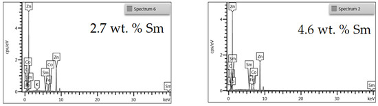
Figure 1.
EDS spectra of Zn-Co-Sm coatings with varying Sm content.
Figure 2 depicts the dependence of samarium, oxygen, and cobalt content in the coatings, on the applied current density and the glycine presence as an additive. A sharp decrement in the Sm and O content, and a sharp increase in cobalt content, may be noticed with the increase in the applied current density, due to the reasons explained below. It is also clear that glycine facilitates the deposition of coatings containing higher Sm and O content, and this phenomenon will also be explained.
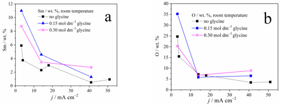
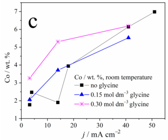
Figure 2.
The weight content of: (a) samarium, (b) oxygen, and (c) cobalt in Zn-Co-Sm composite coatings deposited at different current densities.
Due to the standard electrode potential (<−2.3 V vs. SHE) which is far more negative than the potential of water degradation, the electroreduction of rare earth elements (Ce, Nd, Sm, Gd) to their metallic form (oxidation state zero) is thermodynamically impossible in aqueous media [17]. However, rare earth elements still may be incorporated from the electrolyte into coatings by electrochemical deposition, in two distinct ways.
The first way is the formation of alloy deposits containing rare earth elements in metallic form when the electroreduction of rare metal ions to their zero oxidation state occurs along with the electroreduction of other species, the process called an induced codeposition [18]. In this manner, the Ce, Nd, Sm, and Gd-containing alloys [18], ZnCo-CeO2 [19], and Sm-Se [16] alloys were obtained. A mechanism for aqueous codeposition of rare earth elements containing alloys has been proposed [18], where glycine takes the key role as a complexing agent. Dinuclear coordination complexes are formed, containing iron group element cation and rare earth element cation as nuclei, and glycine ions as ligands. These complex structures, with proper surface orientation, may expose both cations to electroreduction [18].
The second way of RE incorporation in coatings is characteristic of composite coating containing RE, where the rare earth element hydroxide/oxide particles are trapped and surrounded by other elements. The formation of rare element hydroxide occurs through the pH-driven process, where the pH increment in the near-cathodic layer results in the rare element hydroxide precipitation [17]. For example, the Ni coating with Sm(III) and Sm(II) oxides [13], or Ni-cerium oxide coating [14] has been reported.
What is more, the single rare earth element oxide conversion films, resembling the behavior of chromate film, for example, samarium [17], yttrium [20], and cerium [21] conversion coatings, have also been reported. The hydroxide precipitation occurs independently of the cathodic process that causes the pH increment, i.e., the oxygen reduction or hydrogen evolution. However, the morphology of the hydroxide formed depends on the cathodic process inducing the pH increment: the oxygen reduction causes the formation of thin, dense, and non-porous hydroxide deposit, while the hydroxide precipitate formed as a result of hydrogen evolution is a thicker, yet porous, with pores of 100 μm in diameter, due to the gas evolution [17].
The dependence of Sm content on the deposition current density, observed in our and previous works [13,22], is understandable bearing in mind the process that enables the Sm incorporation into the coating. At low plating current densities, i.e., up to 50 mA cm−2, oxygen reduction occurs along with Zn and Co plating. The oxygen reduction is a diffusion-controlled process, it drives the constant pH increment regardless of the current density applied, and so the Sm hydroxide deposition rate is constant. On the other hand, the rate of Zn and Co electroreduction increases with the applied current density which, in turn, causes a decrement in Sm hydroxide content (Figure 2).
However, as the current density, i.e., the overpotential increases, the more intense hydrogen evolution takes part, and this reaction, contrary to the oxygen reduction, is activation controlled: its rate increases with the applied current. Consequently, the Sm hydroxide precipitates in higher quantities at higher current densities, so the Sm amount in the coating increases as well, as reported in [13,22].
In this work, low current densities have been applied, that enable oxygen reduction under diffusion control and hydrogen evolution with low intensity, causing the Sm hydroxide precipitation on one side, but also the electroreduction of Zn and Co cations on the other side. The result is a compact Zn-Co-Sm hydroxide composite coating, with Sm content reaching 11 wt.%. The EDS analysis shows that the O:Sm ratio is close to 3:1 for all current densities, pointing to the fact that Sm(OH)3 particles are incorporated in the Zn-Co coating.
The glycine has been utilized as a complexing agent in our experiments, to elucidate whether it may enable the formation of oxygen-free, ternary Zn-Co-Sm alloy, i.e., the electrochemical reduction of Sm ion through the mechanism proposed by Schwartz et al. [18]. However, the EDS analysis still depicts the Sm hydroxide incorporation in the coating. It is obvious from our results that glycine, as a complexing agent, inhibits the Zn and Co ion reduction, resulting in an increment in Sm hydroxide content. So, as a result, the glycine presence in the plating electrolyte (Figure 3) increases the Sm content in the coating. To sum up, the electroreduction of the Sm(III) ion to its metallic state (oxidation state zero) has not been recorded in our work.
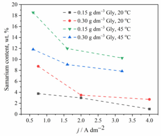
Figure 3.
The effect of temperature and glycine concentration on the Sm content in Zn-Co-Sm composite coatings.
The temperature effect on the chemical composition of the coatings has also been investigated, and Figure 3 shows that the Sm content in an alloy increases when the electrolyte of higher temperature is applied, as also observed earlier [22]. One may assume that the higher temperature enables faster oxygen diffusion to the near cathodic layer, which indirectly increases the rate of Sm deposition, bearing in mind that at low cathodic current densities, the Sm precipitation is oxygen driven process.
3.2. Coating Morphology and Surface Appearance
In order to conveniently grasp the correlation between the presence of Sm inclusions in the coatings and the surface morphology, the SEM microphotographs (Figure 4) of the samples obtained under various conditions, are plotted in the increasing order of Sm content. It is clear that the three parameters: glycine concentration, temperature, and deposition current density, independently influence the Sm content, enabling very fine tuning of the coating chemical composition. The dependence of the coating morphology on the Sm content is also very observable. At low Sm contents (below 2 wt.%), the surface consists of round-shaped agglomerates, typical of Zn-Co or Zn-Fe alloy electrodeposits [23,24]. As the Sm content increases, the agglomerates are replaced with irregular, sharp edge or needle-shaped particles that are less densely packed as Sm content increases. It could be concluded that the occlusion of Sm hydroxide particles in the deposit violates and modifies the formation of alloy agglomerates by the electrocrystallization process. This assumption is supported by the fact that the decrease in the cathodic current density usually results in the increment of the agglomerate dimensions, obeying the cathodic electrocrystallization theory [25], but exactly the opposite is true for the Zn-Co-Sm composites in this work.
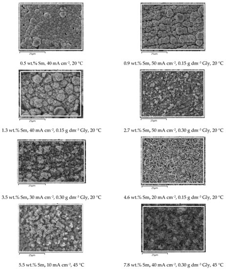
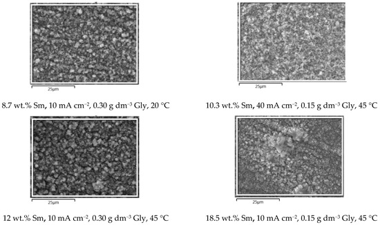
Figure 4.
The SEM microphotographs of the Zn-Co-Sm samples obtained at varying Gly concentrations (0, 0.15, or 0.30 g dm−3), at 20 or 45 °C, and in the current density range of 10–50 mA cm−2.
Visual examination shows that all the samples obtained are dark grey in appearance, the color characteristic for the coatings with Sm-hydroxide inclusion [26], and the standard cross-hatch tape test shows that all the coatings are with good adhesion, i.e., the amount of the removed coating is < 5%. The morphology of the coatings is free of scratches, cracks, peeling, or any other surface defects.
3.3. Phase Composition of the Coatings
In order to obtain insight into the crystalline structure of the obtained coatings, the X-ray diffraction measurements were performed for the Zn-Co-Sm samples deposited from the solution containing 0.15 mol dm−3 glycine, at room temperature, at 5 mA cm−2 (the coating contains 12 wt.% Sm and 2 wt.% Co) and 15 mA cm−2 (coating with 4.5 wt.% Sm and 3.5 wt.% Co). In both XRD plots (Figure 5), one can observe the XRD patterns of at least three distinct crystalline phases: hexagonal zinc η-phase (JCPDS card No. 03-065-3358), Sm2O3 phase (JCPDS card No. 015-0813), and bulk Fe from the substrate (JCPDS card No. 06-0696). The XRD of binary Zn-Co alloy coating (with 1.3 wt.% Co) is shown in Figure 5 as a reference.
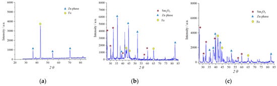
Figure 5.
The XRD patterns of: (a) Zn-Co coating deposited at 5 mA cm−2 and Zn-Co-Sm coatings deposited at: (b) 5 mA cm−2 and (c) 15 mA cm−2.
There are peaks related to the zinc-rich η-Zn phase ( ) in all XRD patterns, owing to the formation of a solid solution of Co with Zn in Zn-Co coatings with less than 5% Co. The presence of Co and Sm caused changes in the crystal lattice which resulted in the shift of 2θ values. Namely, the peak at 36.435°, related to the (002) plane, in Zn-Co was shifted to 35.745° and 35.825° for composite coatings deposited at 5 and 15 mA cm−2, respectively. The peak at 70.254° in Zn-Co alloy coating diminished in composite coatings, whereas additional peaks emerged at 82.448° and 82.368°, related to the (112) plane.
) in all XRD patterns, owing to the formation of a solid solution of Co with Zn in Zn-Co coatings with less than 5% Co. The presence of Co and Sm caused changes in the crystal lattice which resulted in the shift of 2θ values. Namely, the peak at 36.435°, related to the (002) plane, in Zn-Co was shifted to 35.745° and 35.825° for composite coatings deposited at 5 and 15 mA cm−2, respectively. The peak at 70.254° in Zn-Co alloy coating diminished in composite coatings, whereas additional peaks emerged at 82.448° and 82.368°, related to the (112) plane.The peaks denoted with ( ) have been indexed as the cubic Sm2O3 phase. Six diffraction peaks are detected at diffraction angles of 27.16, 31.15., 32.80, 40.98, 56.36, and 60.40°, corresponding to the plane orientation (100), (101), (400), (102), (200), and (004), respectively. The Sm2O3 crystalline phase has been obtained by electrodeposition and reported by other researchers as well [27]. The identification of the Sm2O3 phase confirms the proposed mechanism for the Sm inclusion in the coating: Sm3+ ions are transferred to the cathode; the pH increase occurs due to the oxygen reduction reaction; Sm(OH)3 species are formed and irreversibly adsorbed on the cathode surface [28] and occluded by the reduced metal atoms, and the oxide particles are formed upon the subsequent hydroxide dehydration.
) have been indexed as the cubic Sm2O3 phase. Six diffraction peaks are detected at diffraction angles of 27.16, 31.15., 32.80, 40.98, 56.36, and 60.40°, corresponding to the plane orientation (100), (101), (400), (102), (200), and (004), respectively. The Sm2O3 crystalline phase has been obtained by electrodeposition and reported by other researchers as well [27]. The identification of the Sm2O3 phase confirms the proposed mechanism for the Sm inclusion in the coating: Sm3+ ions are transferred to the cathode; the pH increase occurs due to the oxygen reduction reaction; Sm(OH)3 species are formed and irreversibly adsorbed on the cathode surface [28] and occluded by the reduced metal atoms, and the oxide particles are formed upon the subsequent hydroxide dehydration.The incorporation of Sm caused the increase in the (002) plane intensity, and a decrease in its reflection width, suggesting the formation of bigger grains.
3.4. Corrosion Resistance of the Zn-Co-Sm Coatings
Electrochemical impedance measurements were performed on the Zn-Co-Sm coated samples during immersion periods of up to 72 h in stagnant and aerated 3.5 wt.% NaCl solution, to investigate the effect of the Sm presence in the coating on its corrosion performance. The corrosion behavior of two coatings, with low and high Sm content, will be discussed in more detail, not considering coatings deposited at a higher temperature. The corrosion resistance of Sm-free Zn-Co coatings has been monitored in parallel with the corrosion resistance of Zn-Co-Sm coatings, as a reference for the evaluation of the Sm influence. Yet, the impedance diagrams are not presented in this work, since they may be found in our previous investigations [10,23].
Figure 6 and Figure 7 illustrate the evolution of Nyquist and Bode diagrams as a function of their immersion time in a corrosive medium. The EIS plots related to the corrosion of composite coatings are usually characterized by two time constants: the one at high/middle frequencies is related to the coating layer/corrosion products layer, while the low-frequency one is usually related to processes at the coating/substrate interface or finite thickness layer diffusion process, that takes part as a step in the oxygen reduction [29]. These two time constants, however, are not always easily distinguishable, and in some cases, they are merged and form one, depressed semicircle, as in Figure 6 and Figure 7, denoting that the two processes with the time constants close to each other, occur [29]. For certain immersion periods, the induction tail was observed at low frequencies, the phenomenon often met in impedance diagrams related to zinc alloy corrosion, and usually being ascribed to the adsorption of the intermediate Zn species formed during Zn anodic dissolution, namely Znad+, Znad2+, and ZnOHad+ [30].
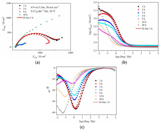
Figure 6.
The (a) Nyquist and Bode: (b) modulus and (c) phase angle plots for Zn-Co-Sm coating with 0.9 wt.% Sm (50 mA cm−2, 0.15 g dm−3 Gly, 20 °C) during exposure to NaCl solution.
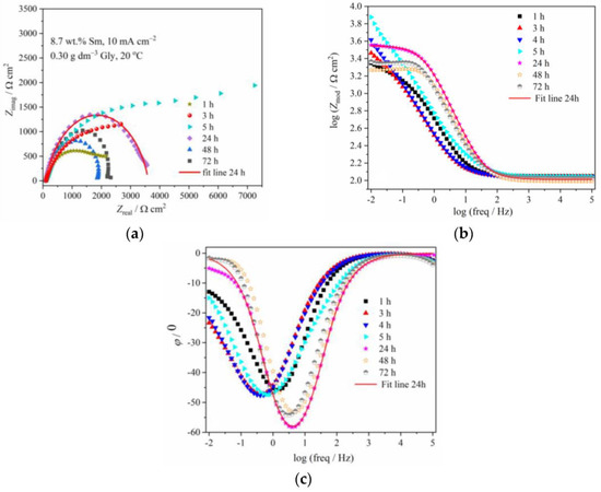
Figure 7.
The (a) Nyquist and Bode: (b) modulus and (c) phase angle plots for Zn-Co-Sm coating with 8.7 wt.% Sm (10 mA cm−2, 0.30 g dm−3 Gly, 20 °C) during exposure to NaCl solution.
In order to evaluate the coating corrosion properties, all the impedance spectra were fitted with the appropriate equivalent circuits shown in Figure 8. For the majority of the spectra, the simple circuit consisting of a parallel connection of a resistor and CPE element was applied, where Rsol, Rct, and CPE are the resistance of the solution, the charge transfer resistance of the corrosion process, and the constant phase element of the double layer at the coating/electrolyte interface. For some cases, the diffusion step was dominant in the corrosion process, and for these samples, the Warburg impedance element (Zw) was added to the equivalent circuit (Figure 8b). An excellent agreement between the experimental data and theoretical curves was obtained as shown by the fitting line that is presented as an example for one immersion time in Figure 6 and Figure 7.
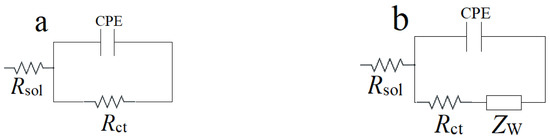
Figure 8.
Equivalent circuits used to fit the experimental EIS data: (a) RctCPE and (b) RctCPE-W.
Table 1 shows the evolution of the coating resistance, Rct, which gives information on the barrier property of the coating. The Rct value of the coating containing low Sm gradually decreases during the immersion time, from 1298 Ω cm2 after 1 h immersion to 403 Ω cm2 after 9 h, indicating coating degradation. It increases to 692 Ω cm2 after 24 h and further to 2821 Ω cm2 after 48 h, the value higher than in the initial exposure time. Such behavior is typical for self-healing, indicating the formation of some low solubility product [5,8,23]. The phase angle peaks for this sample are shifting from –36° at early exposure time, to –28.5° and –24.5° after 3 h and 4 h, respectively, and –14° after 9 h immersion, also pointing to the advancement of corrosion.

Table 1.
Optimum fit parameters for Zn-Co-Sm coatings deposited at two current densities, depending on the immersion time in aqueous NaCl.
Better corrosion stability was achieved with Zn-Co-Sm coating having greater Sm content (8.7 wt.%). The greater initial charge transfer resistance of 2223 Ω cm2 was recorded, which gradually increased to 5994 Ω cm2 after 5 h immersion. Phase angle peak values of –46° during this time corroborate better stability of this coating as compared to one with smaller Sm content. The Rct value decreased during longer immersion, while the phase angle peak was positioned to higher frequencies after 24, 48, and 72 h exposure, reaching –53 to –58°, suggesting restoring protective properties.
The most important feature of the diagrams in Figure 6 and Figure 7 are changes in the Zmod and phase angle over time, denoting significant changes in corrosion rate upon the samples immersion in NaCl. A convenient method for obtaining the polarization resistance of the corrosion process is reading the impedance value at the lowest frequency, i.e., at 10 mHz, which is approximately the value of the polarization resistance measured around the open circuit potential, that may be obtained using classical linear polarization method [31]. The time dependence of the impedance values read at 10 mHz, for these two coatings, is plotted in Figure 9. In order to show the influence of Gly and to compare their behavior with the results for samarium-free, conventional, pure binary Zn-Co alloy coating, the results for these samples are also shown.
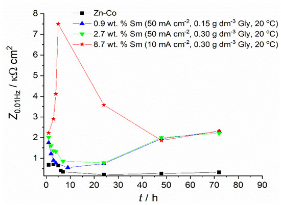
Figure 9.
The impedance modulus values at a frequency of 10 mHz.
Figure 6 and the data in Table 1, related to the coating with only 0.9 wt.% of Sm, depict the typical corrosion behavior of Zn-Co alloy coating in NaCl, also observed in our previous work [23], where the impedance diagrams for the Zn-Co alloy with 3.11 wt.% Co were presented: usually, at the initial immersion time, the corrosion rate of Zn-Co alloy in NaCl is slightly higher than that of pure Zn coating, due to the more active, selective Zn dissolution from the alloy, where cobalt acts as a cathodic element [32]. Upon the immersion continuation, the result of dealloying is the enrichment of the coating surface with cobalt, and the formation of cobalt complex salt, which offers inhibiting and protective effects [3,32]. Such a pattern is nicely observed in Figure 6 and Table 1, where the corrosion resistance firstly decreases, but after 9 h of immersion, continuously increases. There is an additional effect in composite coatings. Namely, upon the ingress of electrolyte through the coating pores Sm diffused, and once it reached the substrate precipitated at the damaged spots forming a low solubility product [32,33], i.e., providing a self-healing effect. The schematic representation of the action of Sm3+ ions is provided in Figure 10, together with the assumed anodic and cathodic half-reactions [33]. This effect is confirmed by the increased charge transfer resistance values. The polarization resistance after 72 h of immersion reached 2320 Ω cm2 and this is considerably higher than the values reported for Zn-Co alloy coatings in NaCl solution as reported in the literature [29,32,34] and shown in Figure 9. These high values are probably the result of the greater stability of low solubility products formed in the presence of Sm as compared to a layer formed on binary Zn-Co alloy coatings. Very similar results were obtained for the composite coating deposited at the same current density and temperature, but with higher Gly in the electrolyte. This coating had three times higher Sm content and slightly higher Zmod values, probably resulting from the more compact morphology.
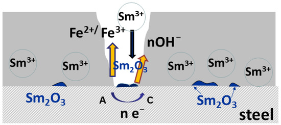
Figure 10.
The schematic presentation of self-healing.
The corrosion behavior of the Zn-Co-Sm coating with 8.7 wt.%, described in Figure 7 and Figure 9 and fitting data in Table 1, is much more interesting. In this case, a very sharp increment in the corrosion resistance is measured in the first 5 hours of the sample exposure to NaCl, however, after this initial period, a sharp fall in the polarization resistance occurs in the 24 h, and so after the 48th hour of immersion, the sample with 8.7 wt.% Sm shows almost equal corrosion resistance as the samples with 0.9 wt.% and 2.7 wt.% Sm. High polarization values in the first hours of immersion may be ascribed only to the self-healing effect, where we assume that the initial corrosion reactions (Zn dissolution and oxygen reduction) caused local pH increase, which was a trigger for the local deposition of Sm oxide [5,6,9]. The second possibility is that the previously incorporated Sm hydroxide was exposed to the electrolyte after the removal of Zn atoms from the interfacial coating surface. Either way, very high resistance values evidence that the corroding rate was significantly reduced and that the corrosion reactions were inhibited.
However, this protective action lasted for a very short period. We assume that either the amount of Sm oxide was too low to cover the entire corroding surface, so the corrosion proceeds at the oxide-free areas of the coating, or the Sm hydroxide particles are detached from the surface over time. After 120 h of immersion, the polarization resistance decreases and approaches values typical for corrosion rate of Zn-Co alloy coating in NaCl medium [30,35].
2H2O + 2e− → H2 + 2OH−
Sm3+ + 3OH− → Sm(OH)3
Sm(OH)3 → Sm2O3 + 3H2O
Still, composite coatings showed higher corrosion stability throughout all exposure times, as can be seen in Table 1. Better properties were achieved with higher Sm content. When the corrosion rate of Zn-Co-Sm coatings is compared to the literature data for other composites with rare metal oxides, it may be seen that the Zn-Co-Sm coatings show approximately ten times higher polarization resistance as compared to the one for Zn-Co-CeO2 [10]. However, the measured polarization resistance for Zn–TiO2·CeO2, Zn–CeO2, and Zn–TiO2 composites was between 1300 and 3000 Ω cm2 [11], very similar to our values. Further analysis is planned to provide deeper insight into the effect of the electrolyte temperature and glycine concentration, on the corrosion performance of the coatings that contain the highest Sm contents.
4. Conclusions
An investigation of the electrodeposition process of the Zn-Co-Sm alloy coating on steel substrate was presented, applying galvanostatic electrodeposition mode, SEM/EDS, XRD, and electrochemical impedance spectroscopy analysis. The increase in deposition current density from 10 to 50 mA cm−2, brings an increase in Co (from ~2 to ~7 wt.%) and a decrease in Sm (from 18.5 to 0.9 wt.%) and O content in the coating. The phase analysis has shown the presence of zinc η-phase, cubic Sm2O3 phase, and bulk Fe phase from the substrate. Based on these results, it is concluded that Sm is incorporated in the Zn-Co-Sm alloy, obeying the hydroxide/oxide formation mechanism. Deposition conditions in broad limits provide coatings black in appearance, of good adhesion and compactness, as was evidenced by SEM. The corrosion resistance in aqueous NaCl, measured by electrochemical impedance spectroscopy as the charge transfer resistance, is significantly higher for the coatings containing Sm, in comparison to the Zn-Co coating. The high corrosion resistance values originate from the action of Sm3+ ions, that, when in contact with the corrosive medium, form insoluble Sm-oxide.
Author Contributions
Conceptualization, M.B. and J.B.B.; methodology, M.B. and J.B.B.; validation, M.B. and J.B.B.; formal analysis, M.B. and S.S.; investigation, M.B. and S.S.; resources, J.B.B.; writing—original draft preparation, M.B.; writing—review and editing, J.B.B.; visualization, M.B.; supervision, J.B.B.; project administration, J.B.B.; funding acquisition, J.B.B. All authors have read and agreed to the published version of the manuscript.
Funding
This work was funded by the Ministry of Science, Technological Development and Innovation of the Republic of Serbia (Contract No. 451-03-47/2023-01/200135).
Data Availability Statement
The data presented in this study are available on request from the corresponding author or co-authors. The data are not publicly available.
Acknowledgments
Authors would also like to acknowledge the help of Rastko Vasilić from the Faculty of Physics, University of Belgrade, for XRD analysis.
Conflicts of Interest
The authors declare no conflict of interest.
References
- Pushpavanam, M. Critical review on alloy plating: A viable alternative to conventional plating. Bull. Electrochem. 2000, 16, 559–566. [Google Scholar]
- Shears, A.P. Zinc-cobalt deposits from an acid chloride electrolyte. Trans. IMF 1989, 67, 67–69. [Google Scholar]
- Abibsi, A.; Short, N.R.; Dennis, J.K. The formation, structure and corrosion behaviour of conversion coatings on zinc alloy electrodeposits. Trans. IMF 1991, 69, 45–49. [Google Scholar] [CrossRef]
- Yuan, W.; Xia, D.; Wu, S.; Zhen, Y.; Guan, Z.; Rau, J.V. A review on current research status of the surface modification of Zn-based biodegradable metals. Bioact. Mater. 2022, 7, 192–216. [Google Scholar] [CrossRef]
- Stankiewicz, A.; Szczygieł, I.; Szczygieł, B. Self-healing coatings in anti-corrosion applications. J. Mater. Sci. 2013, 48, 8041–8051. [Google Scholar] [CrossRef]
- Carneiro, J.; Tedim, J.; Fernandes, S.C.M.; Freire, C.R.S.; Silvestre, A.J.D.; Gandini, A.; Ferreira, M.G.S.; Zheludkevich, M.L. Chitosan-based self-healing protective coatings doped with cerium nitrate for corrosion protection of aluminum alloy 2024. Prog. Org. Coat. 2012, 75, 8–13. [Google Scholar]
- Esser-Kahn, A.P.; Odom, S.A.; Sottos, N.R.; White, S.R.; Moore, J.S. Triggered Release from Polymer Capsules. Macromolecules 2011, 44, 5539–5553. [Google Scholar] [CrossRef]
- Wu, L.K.; Liu, L.; Li, J.; Hu, J.M.; Zhang, J.Q.; Cao, C.N. Electrodeposition of cerium (III)-modified bis-[triethoxysilypropyl]tetra-sulphide films on AA2024-T3 (aluminum alloy) for corrosion protection. Surf. Coat. Technol. 2010, 204, 3920–3926. [Google Scholar] [CrossRef]
- Rosero-Navarro, N.C.; Pellice, S.A.; Durán, A.; Aparicio, M. Effects of Ce-containing sol–gel coatings reinforced with SiO2 nanoparticles on the protection of AA2024. Corros. Sci. 2008, 50, 1283–1291. [Google Scholar] [CrossRef]
- Riđošić, M.; Bučko, M.; Salicio-Paz, A.; Garcia-Lecina, E.; Živković, L.J.; Bajat, J.B. Ceria particles as efficient dopant in the electrodeposition of Zn-Co-CeO2 composite coatings with enhanced corrosion resistance: The effect of current density and particle concentration. Molecules 2021, 26, 4578–4598. [Google Scholar] [CrossRef] [PubMed]
- Nemeş, P.I.; Zaharescu, M.; Muresan, L.M. Initial corrosion behavior of composite coatings obtained by co-electrodeposition of zinc with nanoparticles of Ti and Ce oxides. J. Solid State Electrochem. 2013, 17, 511–518. [Google Scholar] [CrossRef]
- Exbrayat, L.; Rébéré, C.; Ndong Eyame, R.; Steyer, P. Creus, Corrosion behaviour in saline solution of pulsed-electrodeposited zinc-nickel-ceria nanocomposite coatings. Mater. Corros. 2017, 68, 1129–1142. [Google Scholar] [CrossRef]
- Lopez, J.R.; Mendez, P.F.; Perez Bueno, J.J.; Trejo, G.; Antano, R.J.; Stremsdoerfer, T.G.; Meas, Y.G. Samarium additive effect onto the nickel electrodeposition process. J. Electrochem. Soc. 2017, 164, D524–D531. [Google Scholar] [CrossRef]
- Hasannejad, H.; Shahrabi, T.; Jafarian, M.; Rouhaghdam, A.S. EIS study of nano crystalline Ni-cerium oxide coating electrodeposition mechanism. J. Alloys Comp. 2011, 509, 1924–1930. [Google Scholar] [CrossRef]
- Xie, M.; Zhu, L.; Li, W.; Liu, H.; Zhang, T. Electrodeposition of Sm-Co alloy films with nanocrystalline/amorphous structures from a sulphamate aqueous solution. Int. J. Electrochem. Sci. 2017, 12, 11330–11342. [Google Scholar] [CrossRef]
- Jundale, S.B.; Lokhande, C.D. Studies on electrosynthesis of Sm-Se films. Mater. Chem. Phys. 1994, 38, 325–331. [Google Scholar] [CrossRef]
- Ruiz, E.J.; Borges, R.O.; Godinez, L.A.; Chapman, T.W.; Vong, Y.M. Mechanism of the electrochemical deposition of samarium-based coatings. Electrochim. Acta 2006, 52, 914–920. [Google Scholar] [CrossRef]
- Schwartz, M.; Myung, N.V.; Nobe, K. Electrodeposition of iron group-rare earth alloys from aqueous media. J. Electrochem. Soc. 2004, 151, C468–C477. [Google Scholar] [CrossRef]
- Riđošić, M.; Nikolić, N.D.; Salicio-Paz, A.; García-Lecina, E.; Živković, L.S.; Bajat, J.B. ZnCo-CeO2 vs. ZnCo coatings: Effect of CeO2 Sol in the Enhancement of the Corrosion Performance of Electrodeposited Composite Coatings. Metals 2021, 11, 704–723. [Google Scholar] [CrossRef]
- Zhitomirsky, I.; Petric, A. č Electrochemical deposition of yttrium oxide. J. Mater. Chem. 2000, 10, 1215–1218. [Google Scholar] [CrossRef]
- Harvey, T.G. Cerium-based conversion coatings on aluminium alloys: A process review. Corros. Eng. Sci. Technol. 2013, 48, 248–269. [Google Scholar] [CrossRef]
- Wei, J.C.; Schwartz, M.; Nobe, K. Aqueous electrodeposition of SmCo alloys I. Hull cell studies. J. Electrochem. Soc. 2008, 155, D660–D665. [Google Scholar] [CrossRef]
- Ortiz-Aparicio, J.L.; Meas, Y.; Trejo, G.; Ortega, R.; Chapman, T.W.; Chainet, E.; Ozil, P. Electrodeposition of zinc–cobalt alloy from a complexing alkaline glycinate bath. Electrochim. Acta 2007, 52, 4742–4751. [Google Scholar] [CrossRef]
- Bhat, R.; Hegde, A.C. Studies on electrodeposited Zn-Fe alloy coating on mild steel and its characterization. J. Electrochem. Sci. Eng. 2019, 9, 9–16. [Google Scholar] [CrossRef]
- Luo, G.; Yuan, Y.; Li, D.Y.; Li, N.; Yuan, G.H. Current transition of nucleation and growth under diffusion-controlled electrocrystallization: A brief review. Coatings 2022, 12, 1195–1209. [Google Scholar] [CrossRef]
- Riazaty, P.; Naderi, R.; Ramezanzadeh, B. Enhancement of the epoxy coating corrosion/cathodic delamination resistances on steel by a samarium based conversion coating. J. Electrochem. Soc. 2019, 166, C353–C364. [Google Scholar] [CrossRef]
- Lair, V.; Zivkovic, O.; Lupan, L.S.; Ringuedé, A. Synthesis and characterization of electrodeposited samaria and samaria-doped ceria thin films. Electrochim. Acta 2011, 56, 4638–4644. [Google Scholar] [CrossRef]
- Protsenko, V.S.; Danilov, F.I. Kinetic model of composite coatings electrodeposition assuming irreversible adsorption of dispersed particles on a growing metal substrate. J. Electroanal. Chem. 2022, 918, 116463. [Google Scholar] [CrossRef]
- Barranco, V.; . Feliu, S., Jr.; Feliu, S. EIS study of the corrosion behaviour of zinc-based coatings on steel in quiescent 3% NaCl solution. Part 1: Directly exposed coatings. Corr. Sci. 2004, 46, 2203–2220. [Google Scholar] [CrossRef]
- Bučko, M.; Rogan, J.; Stevanović, S.I.; Perić-Grujić, A.; Bajat, J.B. Initial corrosion protection of Zn–Mn alloys electrodeposited from alkaline solution. Corr. Sci. 2011, 53, 2861–2871. [Google Scholar] [CrossRef]
- Magalhães, A.A.O.; Margarit, I.C.P.; Mattos, O.R. Electrochemical characterization of chromate coatings on galvanized steel. Electrochim. Acta 1999, 44, 4281–4287. [Google Scholar] [CrossRef]
- Fratesi, R.; Roventi, G.; Branca, C.; Simoncini, S. Corrosion resistance of Zn-Co alloy coatings. Surf. Coat. Techn. 1994, 63, 97–103. [Google Scholar] [CrossRef]
- Zheludkevich, M.L.; Shchukin, D.G.; Yasakau, K.A.; Mohwald, H.; Ferreira, M.G.S. Anticorrosion Coatings with Self-Healing Effect Based on Nanocontainers Impregnated with Corrosion Inhibitor. Chem. Mater. 2007, 19, 402–411. [Google Scholar] [CrossRef]
- Orhanovic, Z.; Pokric, B.; Furedi, H.; Branica, M. Precipitation and Hydrolysis of Metallic Ions. III. Studies on the Solubility of Yttrium and Some Rare Earth Hydroxides. Croat. Chem. Acta 1966, 38, 269–276. [Google Scholar]
- De Lima-Neto, P.; Correia, A.N.; Colares, R.P.; Araujo, W.S. Corrosion Study of Electrodeposited Zn and Zn-Co Coatings in Chloride Medium. J. Braz. Chem. Soc. 2007, 18, 1164–1175. [Google Scholar] [CrossRef]


Disclaimer/Publisher’s Note: The statements, opinions and data contained in all publications are solely those of the individual author(s) and contributor(s) and not of MDPI and/or the editor(s). MDPI and/or the editor(s) disclaim responsibility for any injury to people or property resulting from any ideas, methods, instructions or products referred to in the content. |
© 2023 by the authors. Licensee MDPI, Basel, Switzerland. This article is an open access article distributed under the terms and conditions of the Creative Commons Attribution (CC BY) license (https://creativecommons.org/licenses/by/4.0/).