Abstract
Compared with cubic Continuously Variable Crown (CVC), quintic CVC presents integrated control capability of quadratic and quartic crown. In order to take full advantage of quintic CVC and have better comprehensive control of the edge wave, center wave, high order wave and complex wave in practical application, it is necessary to further clarify the complicated profile control characteristics of quintic CVC. In this paper, quintic CVC technology in a 1500 mm continuous hot rolling mill production line has been taken as the research object and use finite element method to study its profile control characteristics. Through finite element simulation, an integrated model of rolls and strip was established to analyze the influence of the shifting, bending force and rolling force on strip profile with different strip widths. Both crown adjustment area and transverse stiffness are gained to study the control capability of quintic CVC. The simulation results show that the positive shifting and positive bending of CVC work roll reduce the quadratic crown and increase the quartic crown, and the controlling effect of shifting on both quadratic and quartic crown is more remarkable than that of bending. The control capability of the crown increases with the increase of strip width. That is, wider strip has a larger crown adjustment area. Meanwhile, there is a strong coupling relationship that the increase of quadratic crown can lead to the decrease of the quartic crown, which is not good for the flexible control of strip profile. With the increase of rolling force, the quadratic crown of strip increases significantly, while the quartic crown does not change obviously. Additionally, the increase of strip width significantly increases the transverse stiffness of mill.
1. Introduction
When the mill type is determined, the roll contour is the most direct and active factor in the strip profile control [1]. Continuously Variable Crown (CVC) work roll adopts S-shaped roll contour with anti-symmetric arrangement, which can continuously change the roll gap profile by axial shift [2], thus realizing effective control of roll gap crown. The CVC work roll contour includes cubic CVC and quintic CVC. The roll contour function of cubic CVC is a cubic curve. Accordingly, the profile of no-load nominal roll gap presents parabola, and the quadratic crown can vary linearly with roll shifting [3]. The roll contour function of quintic CVC is a quintic curve. Compared with cubic CVC, the no-load nominal roll gap contains quartic components and has the capability of quartic crown control in the strip profile control [4].
The upstream stands F1~F4 of a 1500 mm continuous hot rolling mill production line adopt quintic CVC work roll. Through work roll shifting and bending, the gap contour under the action of rolling force is changed to realize the strip profile control with different widths [5]. To make full use of various control methods for improving the level of the strip profile control capability in quintic CVC mill, it is necessary to systematically study the strip profile control characteristics of the work roll shifting and bending during the rolling of strips of different width.
At present, cubic CVC roll contour is still used mainly in CVC rolling mill. Many scholars have studied the design method of CVC roll contour in theory. Chen et al. [6] carried out theoretical analysis on the flatness regulation capability of cubic CVC roll contour. Liu et al. [7] studied the relationship between the axial movement of the roll and the effective crown of the roll by mathematical analysis and optimized the design of cubic CVC work roll in a CSP factory from the perspective of rolling technology.
Quintic CVC is created for more complex profile, the research on the design of quintic CVC is carried out late. Combined the actual conditions of the hot rolling mill of Shanghai Meishan Iron & Steel Group Co., Ltd., He et al. [8] determined the coefficient of the quintic CVC roll contour curve in view of both crown ratio and axial force minimization. Li et al. [9,10] analyzed that the crown ratio of quintic CVC roll contour is not constant in the process of roll shifting. Aimed at the problem that the crown ratio keeps changing in the process of roll shifting, they proposed a design method of quintic CVC roll contour curve based on the initial crown ratio. They also pointed out that determining the control range of quadratic crown and quartic crown of no-load ideal roll gap is the key to design quintic CVC.
On account that quintic CVC is not widely used in actual production, the research on the evaluation of quintic CVC is relatively few. But there is a relatively mature research system of studying the strip profile control characteristics, which can be used on quintic CVC’s. Shang [11], Xia [12], Zhang et al. [13] studied on the crown adjustment area of the cubic CVC under the combined action of the shifting and bending force by finite element simulation, which reflects the flexibility of the strip profile control method for the load-bearing roll gap. Wang [14], Hua [15], Dai et al. [16] analyzed the transverse stiffness of roll gap of the cubic CVC mill in view of the influence of rolling force fluctuation, which is caused by changes in temperature and thickness during rolling.
Finite element simulation is an important way to analyze the strip rolling process [17]. Wang et al. [18] used two-dimensional finite element method with variable thickness to analyze the strip profile control capability of hot wide strip rolling mills. Shang et al. [19] analyzed gap contour control characteristics of the downstream stand of a 2250 mm hot rolling mill by ANASYS package. Chen et al. [20] established a finite element analysis model including the bearing boxes, bearings, rolls and strip to analyze the stiffness of the full roll gap.
In this paper, the quintic CVC work roll of 1500 mm rolling mill has been studied. ABAQUS finite element simulation model was established to study the influence law of shifting, bending and rolling force on the strips crown of different width, so as to fully grasp the profile control characteristics of quintic CVC mill.
2. Materials and Methods
2.1. Configuration of 1500 mm Quintic CVC Mill
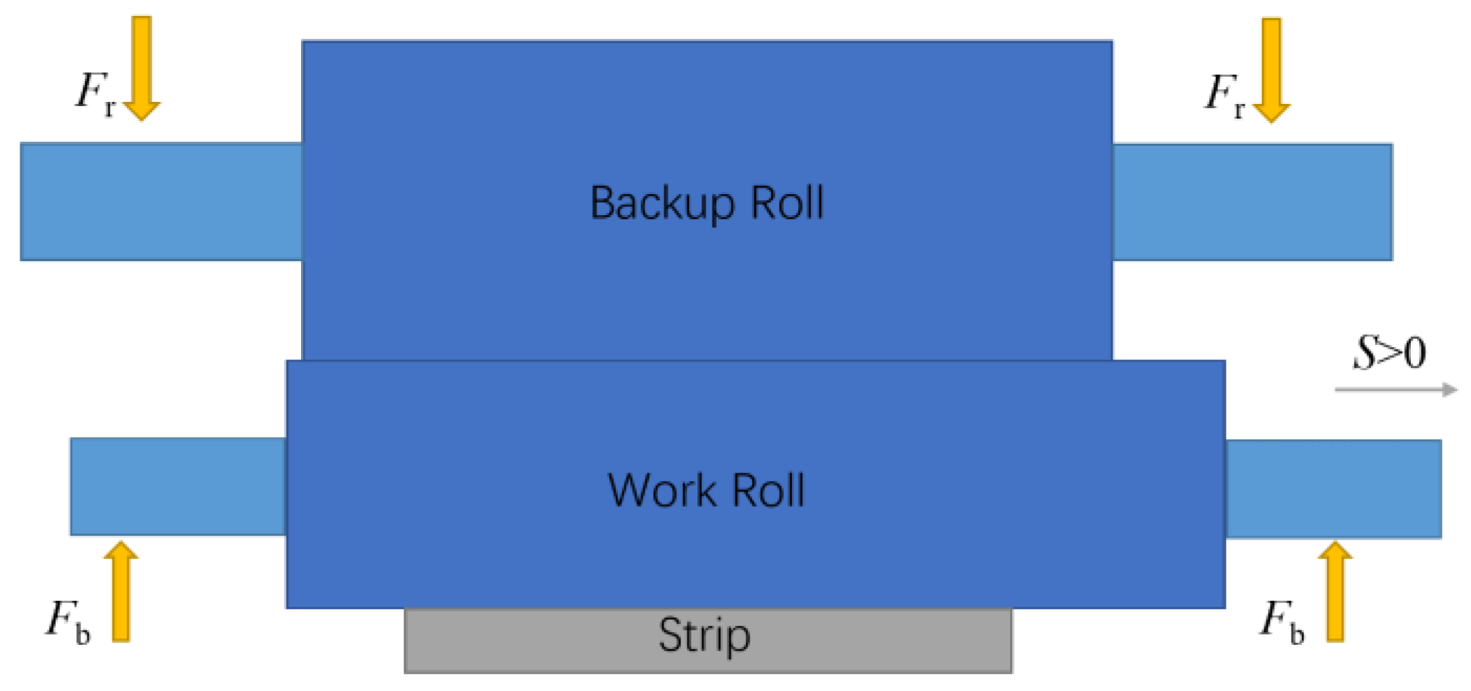
The layout of the rolling mill is shown in Figure 1, and the main rolling width range of 1500 mm mill is 1050~1350 mm. To analyze the strip profile control characteristics of the 1500 mm quintic CVC mill, this paper mainly focuses on to the main means of profile control, such as: bending force Fb, work roll shifting position S and rolling force Fr. For more intuitive comparison of rolling forces at different widths, average unit rolling force q is adopted, which means the ratio of bending force to width.
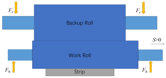
Figure 1.
Layout of CVC mill.
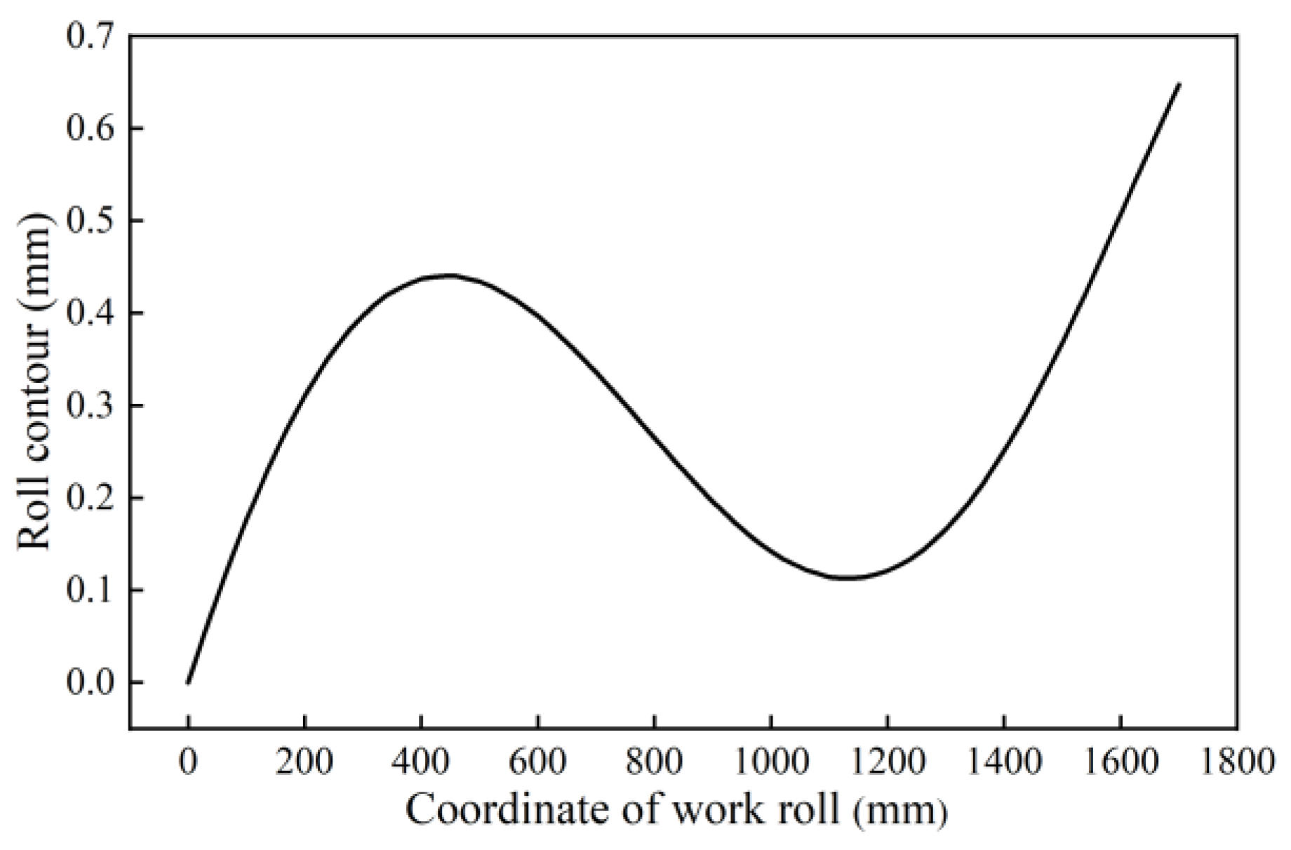
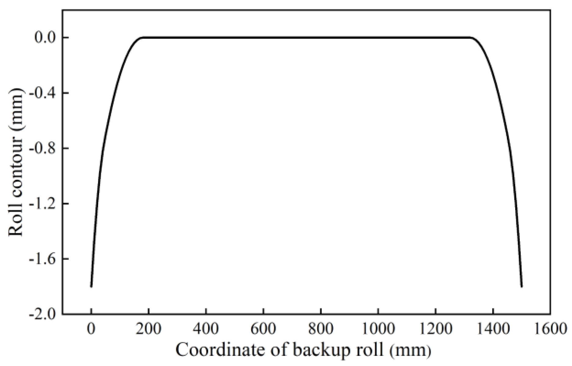
The same quintic CVC work roll contour of the F1~F4 stand is a quintic curve and shown in Figure 2, and shifting range is −100~100 mm. For the quintic CVC work roll contour, the nominal roll gap quadratic crown control range is [0.6 mm, −0.3 mm], and the quartic crown control range is [−0.17 mm, 0 mm]. The control range of work roll bending force is 0~1000 kN. The backup roll of CVC is in the form of plain-barreled roll superimposed chamfering, as shown in Figure 3.
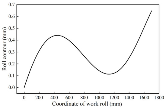
Figure 2.
Work roll contour.
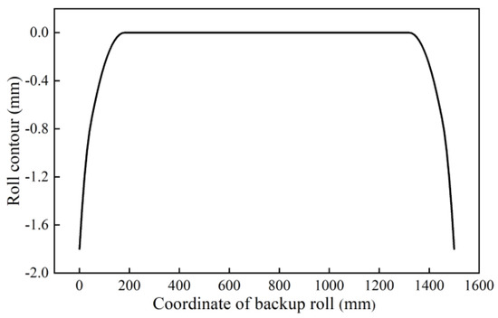
Figure 3.
Backup roll contour.
2.2. Establishment of Finite Element Model
Taking the quintic CVC technology in a 1500 mm continuous hot rolling mill production line as the research object, an integrated finite element model of rolls-strip was established by ABAQUS 2020 shown in Table 1 and Figure 4. In the actual rolling process, the bearing roll gap of the rolling mill is influenced by many factors such as strip tension, rolling torque, material characteristics, lubrication condition, rolling parameters and rolling temperature, and these factors always change during the actual rolling process. It is impossible for the finite element model to take all the factors into account, so the necessary assumptions and simplifications must be made:

Table 1.
Simulation model parameters.
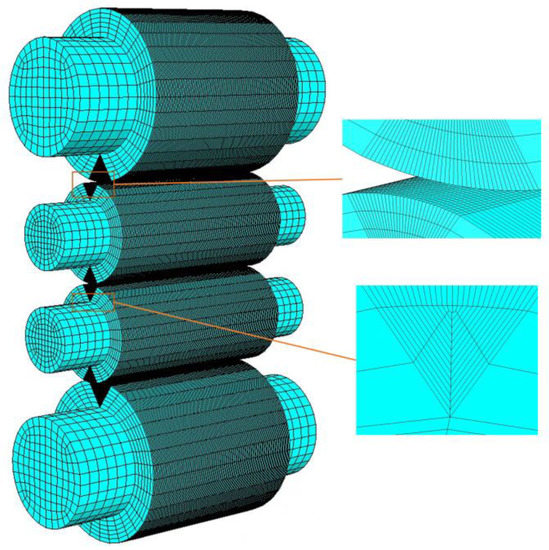
Figure 4.
Finite element simulation model.
- (1)
- Ignore the effects of the strip tension;
- (2)
- The materials of the strip and rolls are uniform and isotropic;
- (3)
- The axis of the roll is coplanar;
- (4)
- There is no relative surface sliding between the rollers;
- (5)
- The influence of rolling temperature is not considered, namely, ignore the influence of thermal crown;
- (6)
- Ignore the rolling torque and the effect of strain rate on rolling;
- (7)
- The material of the strip is uniform and isotropic. Ignore the material‘s change of the strip during rolling and give the corresponding material properties according to the rolling temperature.
The loads are further applied to the model as follows:
- (1)
- For the rolling force, 12.5 kN/mm is the average of 10 mm thickness strip to the actual production situation, and take a deviation of 2.5 kN/mm as the range of rolling force studied. It is applied in the center of the journal section of ends of the backup roll as a concentrated force;
- (2)
- For the bending force, the range of bending force is based on mill capacity. It is applied in the center of the journal section of ends of the work roll as a concentrated force.
The characteristics of the model are as follows:
- (1)
- Work roll and backup roll are elastic body. For material of the rolls, work rolls are made of 42CrMo4, and backup rolls are made of Cr3 type forged steel. For both materials, same material characteristics are adopted shown in Table 2;
Table 2. Material elastic characteristics.
- (2)
- Strip is elastic-plastic body. The material characteristics of strip refer to carbon steel Q235 under temperature of 950℃ and strain rate of 1 s−1 [21], which are shown in Table 2 and Table 3;
Table 3. Material plastic characteristics of strip.
- (3)
- It’s Deflection modelling. The simulation calculation process includes two analysis steps. The first step ensures the contact between the work roll and the backup roll, the work roll and the strip. The second step loads the rolling force and the bending force;
- (4)
- Hard contact is used in normal direction and penalty function is used in tangential direction. The friction coefficient between the backup roll and work roll is 0.12, and the friction coefficient between the strip and work roll is 0.3;
- (5)
- For strip, the thickness is 10 mm, and the strip divided a grid every 10 mm along width direction and into six layers along thickness direction. Strip adopted C3D8R element;
- (6)
- For rolls, the element length in the direction of the length of the roll is 10 mm. In order to ensure better calculation accuracy and obtain faster calculation efficiency, local mesh densification was carried out for the contact area between the backup roll and the work roll, and the contact area between the work roll and the strip. For work roll, the diameter of roll body is 800 mm, and the arc in the places of contact of 190 mm was evenly divided into 30 segments. For backup roll, the diameter of roll body is 1350 mm, the arc in the places of contact of 284 mm was evenly divided into 40 segments. Rolls adopted C3D8R element.
2.3. Data Handling of Strip Profile
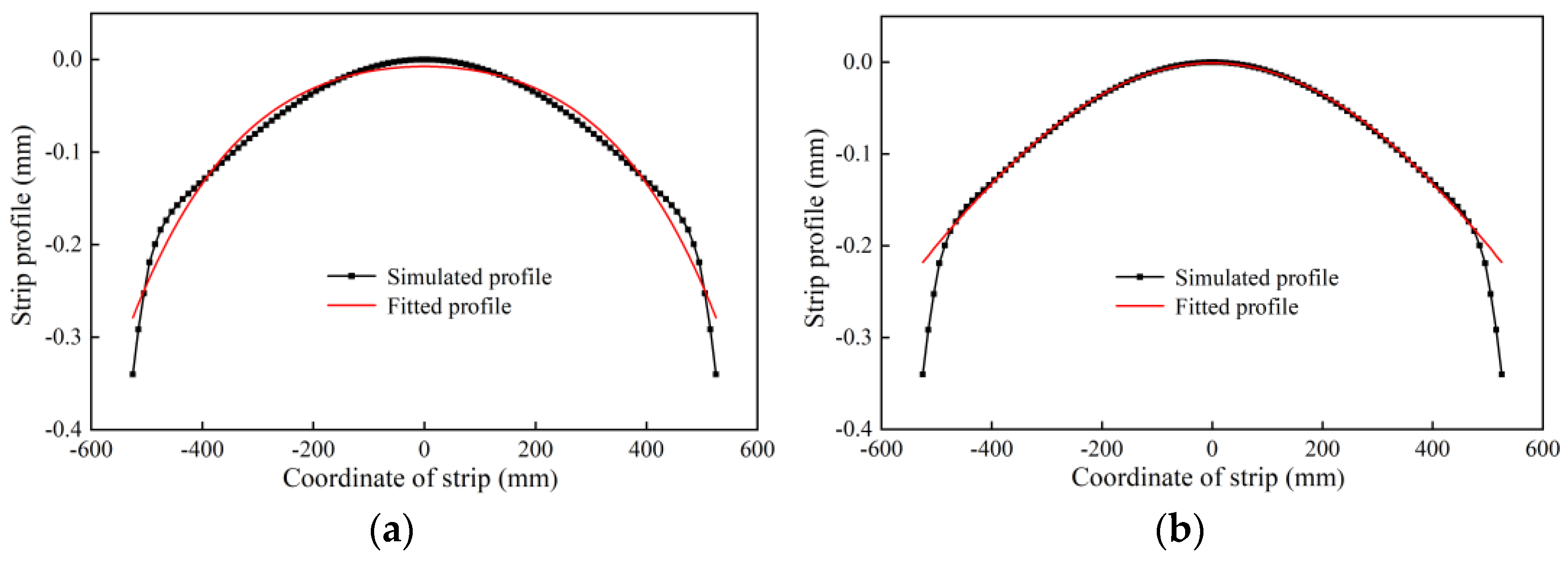
The strip profile can be obtained as shown in Figure 5a by means of finite element simulation analysis. Due to the transverse flow of metal and elastic flattening of roll, there is an obvious edge drop at the edge of the profile, which has a great influence on the calculation of crown. According to the crown calculation method of hot rolling as C40, the 40 mm edge drop area on both sides is not taken into account when calculating the crown value. Quartic curve is adopted for fitting strip profile with the edge drop removed as shown in Equation (1) and Figure 5b. Equations (2) and (3) are used to calculate the strip’s quadratic crown and quartic crown respectively [14].
where, is the fitted quartic curve, is coordinate of strip, are coefficients of the fitted quartic curve for strip profile, is the width of strip, is the quadratic crown, is the quartic crown.
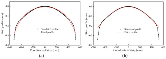
Figure 5.
Data fitting of strip profile. (a) In full-length range; (b) after removing the edge drop.
3. Results and Discussions
3.1. Influence of Shifting on Strip Profile
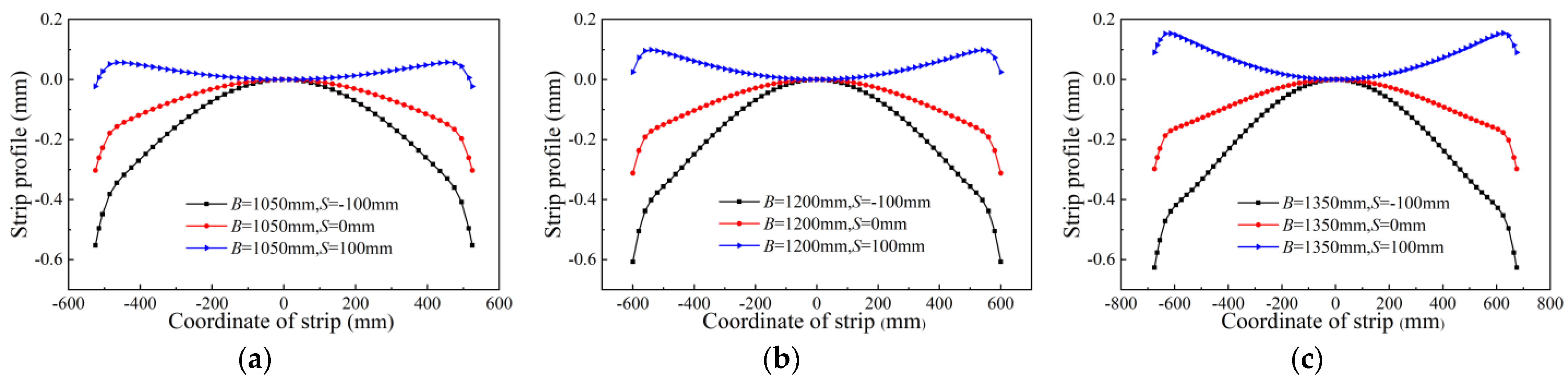
Work roll shifting is one of the most important strip profile control means of CVC mill. This section simulates and analyzes the changes of strip profile with different widths under different shifting position when q = 12.5 kN/mm and Fb = 500 kN. The analysis conditions are shown in Table 4. The simulation results are shown in Figure 6, and the corresponding quadratic and quartic crown values are shown in Table 5. The regulating effect of work roll shifting on strip crown is remarkable. The simulation results show that with the increase of strip width, the quadratic crown control capability increases from 488 μm for 1050 mm to 661 μm for 1350 mm, and the control capability of quartic crown increases from 20 μm for 1050 mm to 56 μm for 1350 mm, which indicates that positive shifting is responsible for reducing the quadratic crown of strip and increasing the quartic crown, and wider strip has a wider range of crown control. On different shifting position, the relationship between the crown and strip width is different. The simulation results of the analysis conditions show that when S = −100 mm, strip quadratic crown increases with the increase of strip width, while quartic crown decreases with the increase of strip width; when S = 0 mm, the quadratic crown firstly increases and then decreases with increasing strip width, while the quartic crown decreases with the increase of strip width; when S = 100 mm, the quadratic crown of strip decreases with the increase of strip width, and the quartic crown almost remains unchanged with the increase of strip width. The results show the complexity of quintic CVC that there are different changes with different strip width in different shifting positions. When using quintic CVC roll contour, with the work roll shifting, the quadratic crown and the quartic crown change in the opposite direction, which need to coordinate in the rolling.
Table 4.
Simulation condition for analyzing the influence of shifting on strip crown.
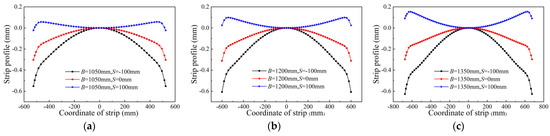
Figure 6.
Influence of roll shifting on strip crown. (a) B = 1050 mm; (b) B = 1200 mm; (c) B = 1350 mm.
Table 5.
Results of the influence of roll shifting on strip crown.
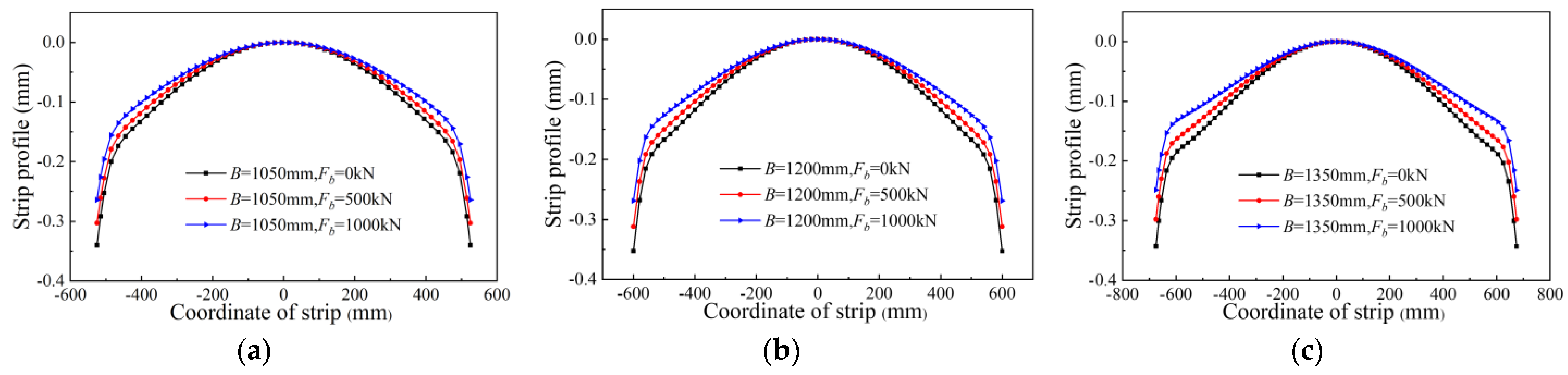
3.2. Influence of Bending Force on Strip Profile
Bending is another important strip profile control way of CVC mill. It is important to simulate and analyze the changes of strip profile with different widths and different bending force when q = 12.5 kN/mm and S = 0 mm. The analysis conditions are shown in Table 6, the results of simulation are shown in Figure 7, and the corresponding quadratic and quartic crown values are shown in Table 7. The analysis results of the conditions show that with the increase of strip width, the control capability of quadratic crown increases from 47 μm for 1050 mm to 65 μm for 1350 mm, and the control capability of quartic crown increases slightly; with different bending forces, the quadratic crown first increases and then decreases with the increase of strip width, while the quartic crown decreases with the increase of strip width. It can be seen that increasing the bending roll will decrease the quadratic crown and increase the quartic crown.
Table 6.
Simulation condition of the influence of bending force on strip crown.
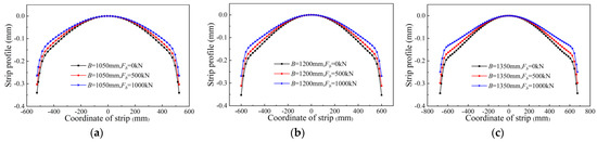
Figure 7.
Influence of bending force on strip crown. (a) B = 1050 mm; (b) B = 1200 mm; (c) B = 1350 mm.
Table 7.
Results of analyzing the influence of bending force on strip crown.
The interaction between quadratic crown and quartic crown is an important characteristic of quintic CVC mill. In the process of controlling strip profile in quintic CVC mill, there are often high order wave shape or other complicated wave shape in the process of controlling edge wave and center wave. However, at present the quartic crown is not measured in the actual production. In order to extend the work roll service time, cycle roll shifting, a rolling mode, is generally set up. When rolling the same specification, in order to meet the requirements of crown setting and stable rolling, full compensation of roll bending to roll shifting should be taken into account, but the complex wave shape caused by the change of quartic crown should be noticed and avoided.
3.3. Crown Adjustment Area of Quintic CVC Mill
According to the calculation results under the action of roll shifting and bending at maximum, middle and minimum value respectively, from finite element analysis, the crown adjustment area of strip with different widths is obtained as shown in Figure 8. As to the measure of the crown adjustment area, the crown adjustment area slightly increases with the increase of the strip width. However, compared with the crown adjustment area of the cubic CVC mill under different widths [12], the change of the quintic CVC is significantly smaller, which indicates that the quadratic crown control capability of the quintic CVC mill does not decrease significantly as the strip becomes narrower. For the position of crown adjustment area, when rolling narrow strip, the change range of quartic crown is relatively small with different shifting position. When rolling wide strip, the change range of quartic crown is larger. Nonetheless, there is a strong coupling relationship between quartic crown and quadratic crown. That is, quartic crown and quadratic crown can not be adjusted by shifting respectively. The increase of quadratic crown inevitably can result in the decrease of quartic crown, which affects the flexible control of strip profile.
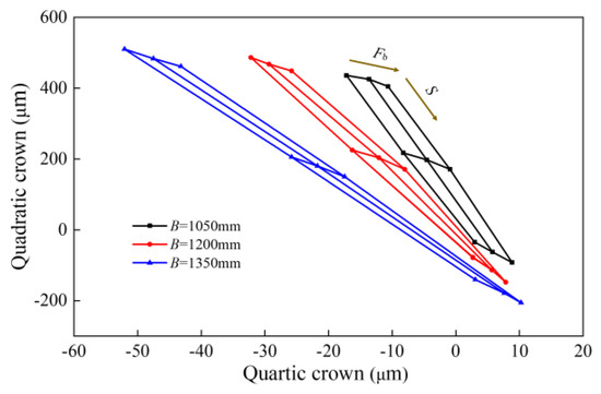
Figure 8.
Influence of strip width on crown adjustment area.
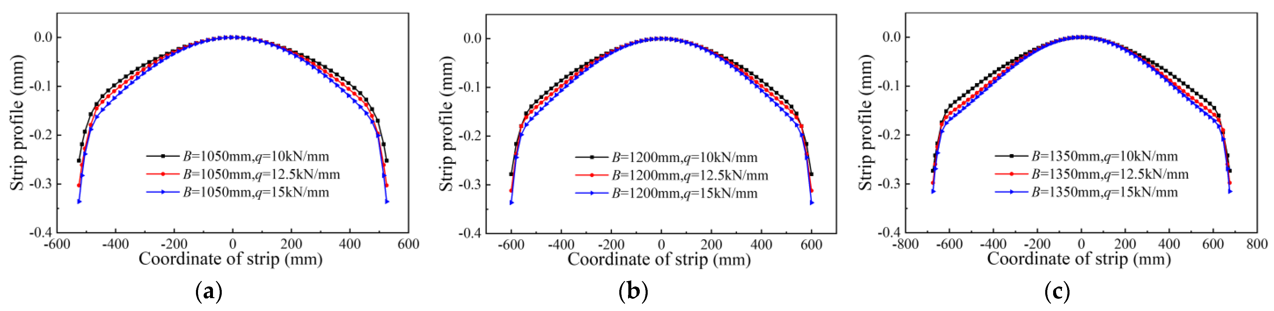
3.4. Influence of Rolling Force on Strip Profile
Under the action of rolling force, the roll deflection deformation occurs, which forms different strip crown. Table 8 shows the simulation condition of strip profile changing with rolling force under different widths when S = 0 mm and Fb = 500 kN. The corresponding strip profile obtained by simulation is shown in Figure 9, and the corresponding quadratic and quartic crown values are shown in Table 9. The simulation results of the 10 mm thickness strip show that when the rolling force per unit width increases from 10 kN/mm to 15 kN/mm, the quadratic crown of strip with width of 1050 mm, 1200 mm and 1350 mm increases by 37 μm, 34 μm and 29 μm respectively. Moreover, the increase of rolling force reduces the quartic crown slightly, which will not show a great effect on the quartic crown of the strip profile. It can be seen that the increase of rolling force per unit width will lead to a increase of quadratic crown of strip steel. Under the premise of meeting the requirements of thickness control, the load distribution can be adjusted to realize the control of strip profile in production mills. When the rolling force fluctuates, it is necessary to compensate by work roll bending in time.
Table 8.
Simulation condition of the influence of rolling force on strip crown.
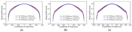
Figure 9.
Influence of rolling force on strip crown. (a) B = 1050 mm; (b) B = 1200 mm; (c) B = 1350 mm.
Table 9.
Results of the influence of rolling force on strip crown.
The transverse stiffness of rolling mill varies with length of harmful contact zone between rolls, which results from different width of strips [20]. According to the data in Table 9, the transverse stiffness of different widths is shown in Figure 10, and the corresponding transverse stiffness values are shown in Table 10. With the increase of the width of the strip, the harmful contact zone between rolls decreases and the transverse stiffness of the rolling mill increases gradually. The finite element analysis results of the 10 mm thickness strip show that the transverse stiffness increases by 66% when the strip width increases from 1050 mm to 1350 mm, which indicates that the width of the strip has a great influence on the transverse stiffness, and other core means of controlling strip profile are less affected by rolling force for wider strip.
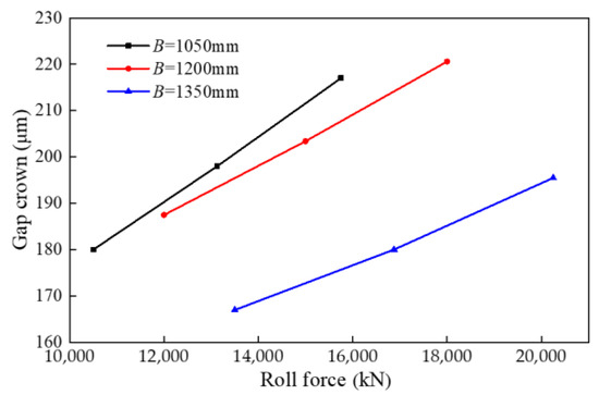
Figure 10.
The influence of the rolling force on the gap crown.
Table 10.
Transverse stiffness with different strip widths.
4. Conclusions
Strip profile control characteristics of 1500 mm quintic CVC mill were studied by finite element analysis, covering the influence of the work roll shifting, bending force and rolling force on strip profile with different strip widths. The simulation results show that the positive shifting and positive bending of CVC work roll can result in the quadratic crown decrease and the quartic crown increase. With the increase of rolling force, the quadratic crown of strip increases significantly, while the quartic crown does not change obviously. Roll shifting directly reflect the capability of crown adjustment of the quintic CVC roll contour and is the most significantly effective way to control the strip profile. The increase of strip width significantly increases the transverse stiffness of mill, which is beneficial to the stability of strip profile control in rolling process. With the increase of strip width, the control capabilities of both quadratic and quartic crown increase by means of roll shifting and bending and are less affected by rolling force.
The finite element simulation indicates the complexity of strip profile control characteristics of quintic CVC mill. Compared with cubic CVC, the quartic crown results in greater control range of quadratic crown over narrow widths, and the measure of crown adjustment area of quintic CVC changes less with the change of strip width, which means quintic CVC is better adapted to width change than cubic CVC. However, the interaction between quadratic crown and quartic crown become more pronounced in quintic CVC mill. Quadratic crown is given priority in computer control [5] while quartic crown can not be considered sufficiently, which can cause formation of high order wave or another composited strip wave.
Author Contributions
Conceptualization, H.L., N.K., Z.L. and B.L.; methodology, B.W.; software, B.W. and Y.W.; validation, H.L., B.W., Y.W., N.K., J.Z., Z.L. and B.L.; formal analysis, B.W.; investigation, B.W., Y.W., N.K., Z.L. and B.L.; resources, Z.L.; data curation, B.W.; writing—original draft preparation, B.W.; writing—review and editing, H.L.; visualization, H.L.; supervision, H.L. All authors have read and agreed to the published version of the manuscript.
Funding
This research was funded by ‘the Scientific and Technological Innovation Foundation of Foshan’ (No. BK22BE015) and ’the National Key Technology R&D Program of the 12th Five-year Plan of China’ (grant No. 2015BAF30B0).
Data Availability Statement
Not applicable.
Conflicts of Interest
The authors declare no conflict of interest.
References
- Cao, J.G.; Zhang, J.; Chen, X.L. Selection of Strip Mill Configuration and Shape Control. Iron Steel 2005, 40, 40–43. [Google Scholar] [CrossRef]
- Li, Z.; Zhou, G.; Yao, C.; Wang, S.; Qi, Z.; Guo, L.; Zhao, D.; He, A. Development and Application of Asynchronous Roll Shifting Strategy of Double Attenuation Work Roll in Hot Rolling. Metals 2022, 12, 1265. [Google Scholar] [CrossRef]
- Zhang, J.; Chen, X.L. Roll Contour Design of 4-High Mill with Variable Crown by Axial Shift. J. Univ. Sci. Technol. Beijing 1994, 16, 98–101. [Google Scholar] [CrossRef]
- Zhang, J.; Zhang, Y.Y.; Xing, B.X.; Du, J.C.; Xing, Y.; Qian, C. Roll Contour Parameters Design Method Based on Minimum Variance of Roll Diameter in CVC Mill. Rolling 2017, 34, 41–45. [Google Scholar] [CrossRef]
- Sun, Y.K. Computer Control of Hot Strip Rolling; Press Metall. Industry: Beijing, China, 2002; pp. 164–176. [Google Scholar]
- Cheng, L.; Kiet Tieu, A.; Jiang, Z.Y. A Design of a Third-order CVC Roll Profile. J. Mater. Process. Technol. 2002, 125, 645. [Google Scholar]
- Liu, F.; Xu, G.; Fan, J. Determination of Roll Contour Parameters of CVC. J. Univ. Sci. Technol. Wuhan 2012, 35, 182–185. [Google Scholar]
- He, W.; Di, H.S.; Xia, X.M. Design of a Five-order CVC Roll Profile. Steel Roll. 2006, 23, 12–15. [Google Scholar]
- Li, H.B.; Zhang, J.; Cao, J.G.; Si, X.; Zhang, S. Control Characteristics Contrast among Cubic CVC, Quintic CVC and Smartcrown Roll Contours. Chin. J. Mech. Eng. 2009, 20, 237–240. [Google Scholar]
- Li, H.B.; Zhang, J.; Cao, J.G. Roll Contour and Strip Profile Control Characteristics for Quintic CVC Work Roll. Chin. J. Mech. Eng. 2012, 48, 24–30. [Google Scholar] [CrossRef]
- Shang, F.; Li, H.B.; Zhang, J. Shape Control Characteristics of 1800 CSP Mill. Iron Steel 2016, 51, 35–40. [Google Scholar]
- Xia, X.M.; Zhang, Q.D.; Dai, J.T.; Zhang, Y.X. Optimized Work Roll Contour on Upstream Stands of 1422 mm Hot Strip Rolling Mill. Iron Steel 2009, 44, 49–51. [Google Scholar] [CrossRef]
- Zhang, X.; Yu, M.; Li, F.; Zhu, G. Research on Strip Shape Adjusting Performance of Ultra-wide 6-h CVC Mill. Min. Metall. 2013, 22, 88–91. [Google Scholar]
- Wang, Y.R.; Yuan, J.G.; Liu, H.M.; Shao, J.; Bian, H.T. Influence of Strip Width on Shape Control Capability of 4-high CVC Hot Strip Mill. Iron Steel 2004, 10, 35–39. [Google Scholar] [CrossRef]
- Hua, H.G.; Shi, Y.Q.; Ren, X.Y.; Du, F.S. Influence of Initial Crown of Work Roll on Strip Shape Adjusting Performance of Ultra-wide 6-h CVC Mill. Iron Steel 2014, 49, 88–93. [Google Scholar] [CrossRef]
- Dai, J.T.; Li, L.J.; Zhang, Z.J. Generation Mechanism and Restrain Measure of Edge Wave on The Medium Plate Rolling. J. South China Univ. Technol. Nat. Sci. 2014, 42, 64–69. [Google Scholar] [CrossRef]
- Graça, A.; Vincze, G. A Short Review on the Finite Element Method for Asymmetric Rolling Processes. Metals 2021, 11, 762. [Google Scholar] [CrossRef]
- Wang, R.Z.; Yang, Q.; He, A.R.; Shao, J.; Bian, H.T. Strip Shape Control Capability of Hot Wide Strip Rolling Mills. J. Univ. Sci. Technol. Beijing 2008, 01, 91–95. [Google Scholar] [CrossRef]
- Shang, F.; Wu, C.H. Analysis on Shape Control Characteristics of Different Width Strip by Ultra-wide Rolling Mill. J. Inn. Mong. Univ. Sci. Technol. 2022, 41, 160–165. [Google Scholar] [CrossRef]
- Chen, X.; Zhang, X.P.; Liu, G.M.; Huang, X.Y. Analysis on Transverse Rigidity along Entire Roll Gap Width of Four-roller Strip Mill. Forg. Stamp. Technol. 2015, 40, 111–116. [Google Scholar] [CrossRef]
- Lv, X.X.; Li, F.; Cao, X.D.; Zhao, S.M. Study on Stress-Strain Curve of Carbon Steel Q235. Shandong Metall. 2007, 1, 41–42. [Google Scholar] [CrossRef]


Disclaimer/Publisher’s Note: The statements, opinions and data contained in all publications are solely those of the individual author(s) and contributor(s) and not of MDPI and/or the editor(s). MDPI and/or the editor(s) disclaim responsibility for any injury to people or property resulting from any ideas, methods, instructions or products referred to in the content. |
© 2023 by the authors. Licensee MDPI, Basel, Switzerland. This article is an open access article distributed under the terms and conditions of the Creative Commons Attribution (CC BY) license (https://creativecommons.org/licenses/by/4.0/).