Abstract
Iron aluminides are considered as candidate materials for high temperature applications for their excellent high temperature corrosion and oxidation resistance. In the present work, iron-aluminide coatings were developed by friction surfacing (6351 aluminum alloy deposited on a low-carbon steel substrate) followed by a diffusion heat treatment. The initial coatings were found to be geometrically homogenous and adhered well to the steel substrate. The heat treatment process was carried out at 550 °C for 48, 72 and 96 h and the resulting coatings were characterized in terms of microstructure, chemical composition, hardness distribution and phase composition. After heat treatment, the coating/substrate interface morphology was modified and presented patterns typical of Fe-Al intermetallic formation, as well as a substantial increase in hardness (>900 HV) relative to the initial as-deposited condition. With the diffusion treatment, initially Fe2Al5 was found to develop in the coatings, which was converted into FeAl2 after longer exposures.
1. Introduction
Iron aluminides (Fe-Al) are alloys with potential use in high temperature applications due to their low cost, density and excellent resistance to oxidation and corrosion. The oxidation resistance of iron aluminides depends on the formation of a stable α-Al2O3 oxide scale on the metal surface, which acts as a diffusion barrier preventing further reaction between the potentially hazardous environment and the underlying metallic substrate [1]. Indeed, materials based on the iron-aluminum system (or its coatings) have been investigated as candidate materials in supercritical water nuclear reactors, environments containing liquid metal such as the heat exchange fluids found in nuclear energy facilities or concentrated solar energy plants [2,3,4,5]. The relatively limited ductility of iron aluminides [6], however, limits manufacturing options, which has prompted research in the use as coatings by various different methods such as: High-Velocity Oxy Fuel (HVOF) spraying [7], cold spraying [8,9], pack aluminizing [10], among others [11].
The friction surfacing process (or friction stir surfacing) is a solid state joining method applied for development of both similar and dissimilar coatings, that has aroused increasing interest from the scientific community in the last decades due to the growing demand for specialized coatings in critical applications [12,13,14,15,16]. In the friction surfacing process, illustrated in Figure 1, a rotating, consumable metal rod is forced onto a flat metallic substrate. Friction between the contact surfaces causes an increase in temperature and plastic deformation of the metals at the consumable rod tip, leading to the formation of a characteristic flash. Liu et al. [17] followed the temperature evolution during FS experiments involving deposition of stainless steel coatings on mild steel and showed that during the initial contact temperature increases rapidly before stabilizing in a quasi-steady state. After the initial vertical plunge, linear motion of the consumable rod relative to the substrate allows the formation of a longitudinal deposit [18]. During the process a number of mechanical and metallurgical phenomena are known to take place. Fukakusa [19] originally proposed that the coating material is transferred due to shearing along rotational contact plane formed between consumable rod and deposit. The process results in intense plastic deformation at high temperature and elevated strain rates leading to a fine-grained recrystallized microstructure [20,21]. In the absence of fusion during metal transfer, the friction surfacing process is an interesting possibility for joining dissimilar materials considered otherwise metallurgically incompatible because of differences in thermal or physical properties, such as e.g., iron and aluminum alloys [22].
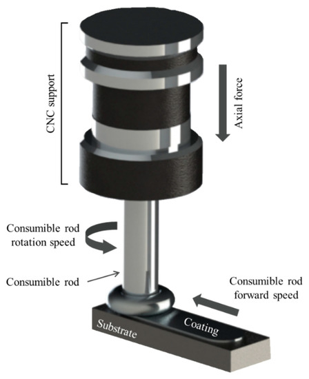
Figure 1.
A schematic illustration of the friction coating process applied to the deposition with the identification of the main process parameters.
Because of these positive characteristics, the friction surfacing process has been continually developed in recent years, with variations such as Friction Stir Forming, Friction Stir Deposition and Lateral Friction Surfacing [16,23,24]. However, the literature on friction surfacing of intermetallic alloys in general or iron aluminides is scarce. Recent investigations have reported the use of friction surfacing (and friction stir processing, an analogous technique) to manufacture composite Al-alloy coatings reinforced with Ni and Zr aluminides, resulting in improvements of mechanical properties, corrosion and wear resistance [25,26,27]. Considering iron aluminide coatings developed by friction surfacing specifically, probably the first work was reported by Udaya Bhat et al. [28] who submitted an Al-alloy coating deposited onto a steel substrate to short-term annealing at 700 °C and analyzed the subsequent intermetallic phase formation. A similar processing route was later employed by Troysi and Brito [29], who analyzed the electrochemical corrosion behavior of an Fe2Al5 coating on mild steel substrate which was obtained by friction surfacing followed by a diffusion treatment. More recently, Silva et al. [20] analyzed dynamic recrystallization in iron aluminide coatings obtained by direct deposition of a cast intermetallic Fe-Al-C alloy.
In the present investigation, we sought to develop iron aluminide coatings on a conventional low-carbon steel substrate by combining friction surfacing of an Al-alloy followed by a diffusion heat treatment [28,29]. The main contribution of this work is the analysis of the substrate/coating interface over time, since diffusion across the interface can alter microstructure and properties of the iron aluminide coating, which is important to be considered for high temperature applications. By applying the friction surfacing process, relatively thick (>1 mm) coatings can be obtained, while avoiding some of the problems associated with conventional spraying or welding techniques such as solidification induced cracking, dilution, residual stresses, among other issues [13,18].
2. Materials and Methods
2.1. Materials
To carry out this research, hot-rolled AISI 1020 steel sheets were acquired (0.193 wt.% C-0.530 wt.% Mn-0.131 wt.% Si), with dimensions (length × width × thickness) of 100 × 50.8 × 6.35 mm and consumable rods of AA6351 aluminum alloy (0.167 wt.% Fe-0.652 wt.% Mg-0.606 wt.% Mn), with 15.875 mm in diameter and 100 mm in length, in the extruded condition. The chemical composition of the materials used in the experiments was determined by X-ray fluorescence (Rigaku ZSX Primus II equipment, The Woodlands, TX, USA). Before friction surfacing, the AISI 1020 steel sheets were mechanically ground and exhibited an average surface roughness Ra equal to 3.05 ± 0.059 µm. The AA6351 consumable rods were heat treated for solubilization and homogenization at 450 °C for one hour. In addition, the consumable rod faces were prepared by turning in order to ensure a flat surface and uniform contact with the substrate during processing.
2.2. Friction Surfacing Procedure
The deposition process was carried out in a ROMI Discovery 560 machining center with a maximum 11 kW power output that supports rotation speeds up to 10,000 rpm. The deposition parameters were based on previous investigations in which the same experimental setup was used [30,31], with a rotation speed of 2500 rpm, forward speed (or feed rate) of 150 mm/min and ratio between the forward (horizontal) and vertical motion of 0.5. This procedure is necessary in non-dedicated equipment that lack control of the axial force exerted by the consumable rod during deposition, and the ratio of 0.5 was employed based on previous analyses which revealed this condition allowed for superior adhesion between the Al-alloy coating and low carbon steel substrate [32]. The total coating length was of 50 mm, with an initial dwell time of 20 s in which the consumable rod is plunged into the substrate to a depth of 2 mm. During deposition, temperatures were monitored with the assistance of a FLIR infrared camera, that allowed acquisition of the peak temperature in the analyzed field of view. The camera was kept at a 0.8 m distance from the experiment and was calibrated for operation in a temperature range of −20 to 1200 °C. After friction surfacing, coated samples were submitted to a diffusion heat treatment to obtain an iron aluminide coating from the original Al-alloy deposit. The temperature selected for analysis was 550 °C, just below the 554 °C solidus temperature of the AA6351 alloy. The times selected for diffusion were 48, 72 and 96 h, based on previous studies concerning diffusion of Al coatings on steel substrates [29,33].
2.3. Characterization Procedures
Microstructure characterization was performed by optical microscopy (OM) and scanning electron microscopy (SEM) coupled with an energy-dispersive spectroscopy (EDS) analyzer. The analyses were conducted on the coating cross-section, and sample preparation followed standard metallographic procedures, that involved grinding in SiC paper followed by polishing in a diamond suspension down to a 0.25 µm finish. Etching of the samples was accomplished by employing a 5%Nital solution. Further information regarding phase composition of the developed coatings was obtained by X-ray diffraction (XRD). The XRD diffractograms were recorded using a Cu Kα radiation source, operating at 40 kV and 30 mA, with a step of 0.02° over a 2θ range of 30 to 100°. The scan rate utilized in the XRD tests was of 2° per minute. The mechanical properties of the coatings were assessed in terms of Vickers microhardness profiles determined along the coating cross-section. The measurements were performed using a Shimadzu (Kyoto, Japan) microhardness tester, model HMV-2T with a load of 490.3 N (0.5 HV) and holding time of 20 s. All hardness measurements were performed three times at equivalent distances form the coating/substrate interface.
3. Results
3.1. Coating Deposition
The deposition process is analyzed in Figure 2, in which an overview of the as-deposited coating is also presented, while the corresponding cross-section analysis is presented in Figure 3. The maximum temperature registered during deposition in Figure 2a–d is indicated in the top left corner of each picture.
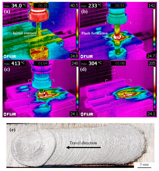
Figure 2.
Analysis of the deposition process and final coating: (a) initial contact between consumable rod and substrate sheet, (b) flash formation at the consumable rod tip, (c) deposition, (d) retraction of the consumable rod and cooling and (e) top view of the as-deposited AA6351 coating obtained after friction surfacing on a AISI 1020 low carbon steel substrate.
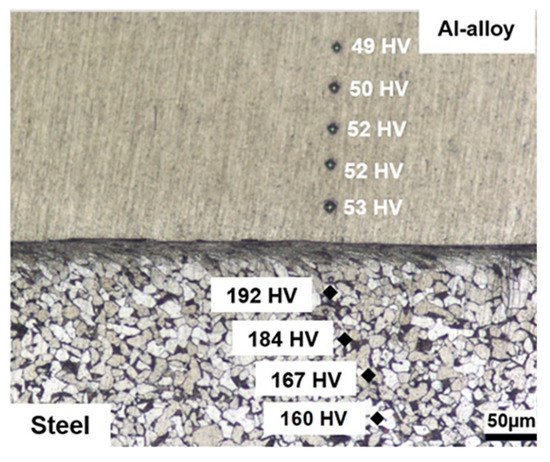
Figure 3.
OM cross-section analysis of the as-deposited coating (Nital 2% etch) revealing homogenous hardness in the coating and hardening on the substrate side of the interface due to plastic deformation during the deposition process.
In Figure 2a, the initial contact between the consumable rod tip is visualized. The thermographic data indicate that after this initial contact, in which the consumable rod is slowly plunged vertically into the substrate, temperatures rise rapidly, and flash formation can be noticed in Figure 2b. Once the downward vertical motion is completed, the actual deposition takes place with a forward motion of 150 mm/min, which is illustrated in Figure 2c. The average deposition temperature is close to 400 °C, in agreement with a previous investigation [30]. Throughout the deposition process, the maximum temperature is consistently observed at the tip of the consumable rod i.e., at the contact surface with the substrate. After completing the 50 mm horizontal motion with a simultaneous 25 mm downward plunge, the consumable rod is retracted as shown in Figure 2d. Because of the higher thermal conductivity of the Al-alloy, after retraction of the rod, elevated cooling rates take place in the coating and the maximum temperatures are now observed on the surface of the carbon steel sheet. In Figure 2e, it is possible to notice that the coatings are homogenous in terms of width, except for the initial portions of the deposit which is formed during the initial vertical downward plunge of the consumable rod. In addition, it is possible to notice a mechanically continuous coating/substrate interface, which is absent of cracks or pores in its central section (shown in Figure 3). The characteristic undercut [18] caused by the inhomogeneous pressure distributions during deposition associated with flash formation at the consumable rod tip (Figure 1) is not analyzed in Figure 3.
The coatings also presented uniform hardness distributions, with an average hardness value of 51.2 HV (±2 HV). On the steel side of the interface, it is possible to notice that ferrite grains and pearlite colonies become compressed and elongated parallel to the interface indicating that plastic deformation takes place in the substrate during deposition as has been noticed in other solid-state joining processes such as explosion cladding [34]. Indeed, hardness values increase in the steel in these highly deformed regions from about 160 HV to 192 HV indicating that strain-hardening takes place. This increase in hardness can be expected, since the deposition temperature was of approximately 400 °C, which is not sufficient to cause recrystallization during the relatively short deposition time. Thus, common features present in the heat-affected zone in conventional welding processes such as the formation of acicular ferrite were not observed in the present investigation and are consistent with the assumption that the process takes place entirely in the solid-state [18].
3.2. Diffusion Treatment
3.2.1. Coating Microstructure
The effects of the diffusion treatment carried out at 550 °C can be observed in Figure 4a,b which reveal, respectively, the characteristics of the coating/substrate interface and microhardness profiles determined along the samples cross-section. Concerning the near interface microstructure, it is possible to notice that the coating now exhibits what appear to be intrusions into the substrate where previously an essentially planar interface was observed. The development of such an interface in Fe and Al diffusion couples has been previously reported in literature, e.g., by [35,36] and leads to an increase in the effective contact area between substrate. The sharp modification of the interface morphology corroborates the sound mechanical integrity between substrate and coating obtained after the friction surfacing process, as suggested by the defect-free interface depicted in Figure 4a. In addition, no further signs of plastic deformation on the substrate side of the interface can be observed in contrast to the results presented in Figure 3. Instead, the microstructure consists now of equiaxed grains most likely a consequence of recrystallization followed by grain growth during the prolonged heat treatment process.
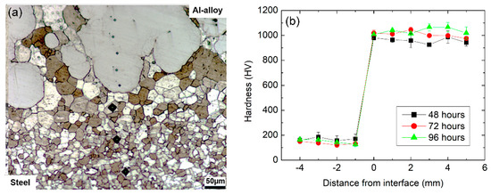
Figure 4.
Cross-section analysis after heat-treatment at 550 °C: microstructure at the substrate/coating interface of a sample treated for 96 h (a) and microhardness profiles according to heat treatment time (b).
The diffusion treatment also led to a significant hardness increase in the coating relative to the initial as-deposited condition, with average hardness values of 959 ± 37, 1010 ± 24 and 1037 ± 35 HV obtained after 48, 72 and 96 h, respectively, as shown in Figure 4b. The elevated hardness values observed suggest the formation of Al-rich intermetallic phases such as FeAl3, FeAl2 or Fe2Al5 in the coating [33,37,38]. For all heat treatment times, coating hardness was found to be consistently superior to 900 HV, with an observable increase in hardness for the longer diffusion times of 72 and 96 h in comparison to the 48 h treatment. Furthermore, hardness in the coatings is relatively uniform, indicating homogeneity in the eventual formation of intermetallic compounds through coating thickness. It is also noted that the heat-affected zone on the substrate extends for approximately 0.15 mm.
An overview of the changes in chemical composition can be seen in Figure 5a–c, which exhibit, respectively, EDS maps obtained after the 48, 72 and 96 h heat treatments. The average composition value in the coatings close to the interface were 54.7 wt.% Al and 42.9 wt.% Fe for 48 h, 55.1 wt.% Al and 43.4 wt.% Fe for 72 h and 55.4 wt.% Al and 41 wt.% Fe 96 h. No amounts of Al were detected in the substrate, and minor quantities of C and Mn were detected in each sample, with no significant variations according to diffusion time.
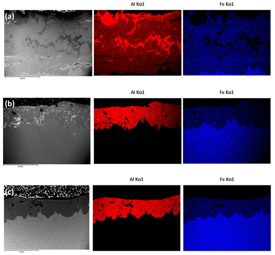
Figure 5.
Cross-section overview of the samples after heat treatment at 550 °C with EDS maps showing an overall homogenous distribution of Al and Fe in the coating: (a) 48 h, (b) 72 h and (c) 96 h (images obtained in BSE imaging mode).
The coating obtained with the 48 h treatment appears to be more chemically heterogenous in comparison to the coatings obtained after 72 and 96 h, as can be seen by the Al-rich regions identified in Figure 5a. In the 48 h coating, it is also possible to notice the presence of horizontal cracks, parallel to the substrate. According to a previous investigation, these are probably developed during sample preparation (cutting, grinding) [33] because of the elevated hardness and brittleness of the intermetallic compounds that are expected to be found in the coating—especially considering that no cracks were observed in the coatings obtained after the 96 h treatment. With longer diffusion times, however, it is possible to notice the presence of porosities in the coatings, which have been attributed to the Kirkendall effect in previous investigations of diffusion involving Fe and Al [35,39].
In order to confirm the development of an intermetallic coating with the diffusion heat treatment, phase analysis by XRD was conducted on the top surface of the coatings and the results are presented in Figure 6. Given the relatively shallow X-ray penetration depth, the results shown in Figure 6 do not provide direct information concerning phase composition in the vicinity of the substrate interface or the overall coating. However, considering the homogenous hardness and composition distributions verified in Figure 4 and Figure 5, the XRD data can be considered to represent at least in general the phase composition in the coating (with the exception of possible local variations) The results clearly indicate that a change in structure occurs after 72 h with no further transformations up to the 96 h. The free energy of formation (ΔG0, in cal/g.mol-Al) of different Fe-Al intermetallics was compiled by Kumar and co-workers [10] as a function of temperature (T):
Fe3Al: −13,660 + 19T,
FeAl: −11,580 + 1.14T,
FeAl2: −9750 + 1.28T,
Fe2Al5: −9630 + 1.43T,
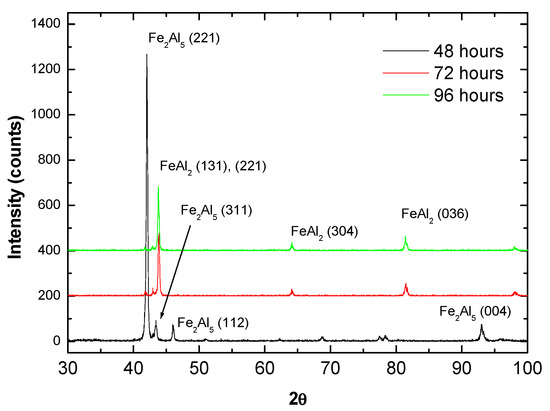
Figure 6.
XRD analysis of the coatings after heat treatment at 550 °C for 48, 72 and 96 h indicating a conversion from Fe2Al5 to FeAl2 with time.
The ΔG0 values obtained for Fe3Al, FeAl, FeAl2 and Fe2Al5 at 550 °C are, respectively, 2037 cal/g.mol, −10,640 cal/g.mol, −8697 cal/g.mol and −8453 cal/g.mol. Hence, in principle possible phases to be considered from this initial selection are FeAl, FeAl2 and Fe2Al5 and the best correspondences were found to be Fe2Al5 for 48 h and FeAl2 for the remaining heat treatment times, as shown in Figure 6. Although a certain overlap exists among diffraction angles of different Fe-Al phases, such as FeAl2 and FeAl for instance [40], the results are consistent with the expected phase composition according to the Fe-Al phase diagram [41] and with the hardness values presented in Figure 4b. For instance, Matysik et al. [38] provide a summary regarding hardness of Fe-Al compounds reporting values between 900 and 1050 HV for FeAl2 and between 950 and 1100 HV for Fe2Al5 (the hardness of FeAl is relatively lower, approximately 660 HV [33]).
It is worth noticing that in the present case, superior average hardness values were found for the longer diffusion times, which were associated with the formation of FeAl2, even though Fe2Al5 is expected to exhibit superior hardness in general. This can be explained by the fact that after 48 h diffusion, as shown in Figure 5a, the coating is still chemically inhomogeneous and the Al-rich zones previously mentioned, might be ascribed to intermetallics with relatively inferior hardness, such as FeAl3 (between 800 and 980 HV [38]). Such a development would be consistent with a formation sequence that starts with Fe2Al5, followed by FeAl3, FeAl2 and finally FeAl (although in the present study this last step was not achieved) as reported previously by Yang et al. [42] who investigated intermetallic formation in roll bonded Al-steel sheets. Similar observations were made by Naoi and Kajihara [43] who investigated reactive diffusion between Fe and Al and concluded that Fe2Al5 develops faster in comparison to FeAl, FeAl2 and FeAl3 for diffusion conditions (time and temperature) similar to those employed in the present study.
3.2.2. Coating-Substrate Interface Analysis
The results presented in Figure 5 suggest a sharp composition gradient near the substrate/coating interface, which is further analyzed in Figure 7 in terms of EDS line scans performed on sample cross-sections. The Fe concentration gradient (towards the coating) was arbitrarily assigned a negative value while the Al concentration gradient (towards the substrate) was considered positive. The Al concentration gradients were found to be 0.21, 0.05 and 0.07 µm−1 after 48, 72 and 96 h, respectively. In turn, the Fe concentration gradients were −0.26, −0.05 and −0.08 µm−1, after 48, 72 and 96 h, respectively.
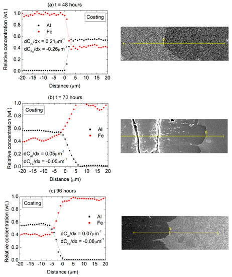
Figure 7.
Composition profiles (Al and Fe) across the coating/substrate interface after (a) 48 h, (b) 72 h and (c) 96 h at 550 °C with the corresponding positions of the EDS scans (BSE imaging mode).
The actual values of the concentration gradients at the interface ought to be considered critically since they are also a reflection of the EDS spot size resolution. However, in qualitative terms it can be seen that relatively steeper gradients are present in the initial stages of the diffusion process, with a larger difference in the Al and Fe concentration gradients (in terms of absolute values) after 48 h compared to the other heat treatment times, suggesting an initial transient diffusion behavior. This finding is consistent with the observations of Kobayashi and Yakou [33], who revealed transient behavior for shorter diffusion times in Fe-Al diffusion couples. For the 72 and 96 h treatments, on the other hand, the concentration gradients across the interface are significantly reduced and the values for Al and Fe are practically equivalent. It appears, therefore, that after 48 h at 550 °C the system transitions to a steady-state diffusion behavior, with a constant diffusion flux across the interface and similar Fe and Al composition gradients.
It can further be observed that the concentration gradient across the substrate/coating interface appears to be related to the phase composition in the coating. For the 48 h diffusion time, according to the XRD results presented in Figure 6, the steeper Fe and Al concentration gradient reflects the changes in composition across substrate and a (mostly) Fe2Al5 layer, while the lower concentration gradients observed after 72 and 96 h reflect the boundary between the substrate and a FeAl2 layer. Considering that after 72 h the phase composition in the coating remains stable as does the average chemical composition in the coating (Figure 5b,c), and the composition gradients across the substrate interface, it appears that the diffusion coatings might remain stable at the investigated temperature of 550 °C.
The interface microstructure of the sample treated for 96 h was further analyzed by SEM/EDS, and the results are presented in Figure 8. The labels “A”, “B” and “C” indicate the location of EDS spot measurements and the corresponding relative compositions of Fe/Al are shown in Table 1. With this higher magnification image, it is possible to notice the presence of a thin (~5 to 10 µm) layer at the interface (spot B) with a lower relative Al content compared to the remainder of the coating. Because of the reduced thickness of this layer, it was not detected on the composition gradients shown previously (Figure 7). From the composition analysis presented in Table 1, it is unclear whether an intermetallic compound with elevated Fe-content is formed, or if the layer corresponds to solid solution of Al in Fe.
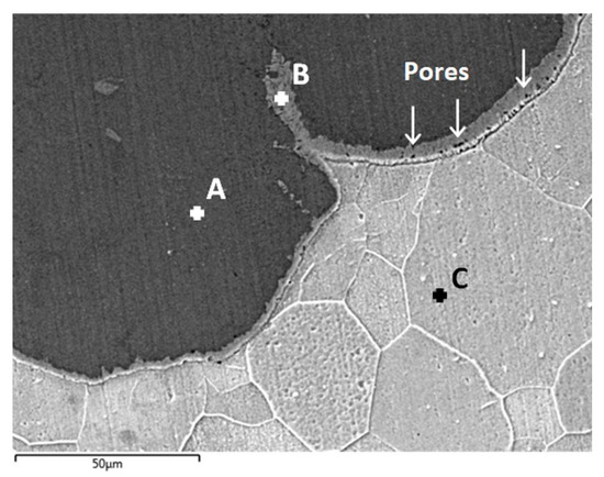
Figure 8.
Detailed cross-section analysis of the substrate/coating interface by SEM/EDS after heat treatment at 550 °C for 96 h (BSE imaging mode): coating (spot A), interface layer (spot B) and substrate (spot C).

Table 1.
Composition of EDS spots indicated in Figure 8 (values in relative weight percentage).
A number of small pores (<5 µm) could be detected in the layer, as indicated by the arrows in Figure 8. These are similar in morphology and size to Kirkendall pores detected in previous investigations [35,44] and are significantly smaller compared to the pores that can be seen in Figure 5b,c. Concerning the origin of these larger porosities, a second possible cause is the change in phase composition observed in the coating, from Fe2Al5 to FeAl2, which corresponds to an increase in mass density with the diffusion process by the incorporation of Fe. The specific weight of the initial Al-alloy coating is approximately 2.7 g/cm3, which increases to 3.96 g/cm3 with the formation of Fe2Al5 and subsequently to 4.80 g/cm3 with the conversion to the FeAl2 structure. In either case, it is clear that while extending heat treatment times leads to homogenization of the coating, physical deterioration is observed with an increase in the amount of porosities and the consequences for further applications of such coatings remain to be investigated.
4. Conclusions
In the present investigation, Al-alloy (6351) coatings were deposited on low carbon (1020) steel by the friction surfacing process. Subsequently, heat treatments led to the formation of intermetallic iron aluminide coatings and the following conclusions could be drawn:
- Coatings became chemically homogenous after 72 h of heat treatment at 550 °C.
- The coatings evolved from the initial Al-alloy composition to Fe2Al5 after 48 h and to FeAl2 after 72 h, which remained unaltered up to 96 h of heat treatment.
- Composition profiles and gradients across the substrate/coating interface remained stable after 72 h diffusion.
- With prolonged heat treatment the development of porosities in the coating was observed.
The influence of temperature on the diffusion behavior of the solid-state formed joint was not analyzed in the scope of the present study. As such, further developments in the field might benefit from investigations of the diffusion behavior over longer times, different temperatures, as well as more detailed microstructure analyses of the intermetallic coatings.
Author Contributions
Conceptualization, N.M., F.T., G.C.d.S. and P.B.; methodology, N.M., C.E.d.S., Í.B.d.S. and A.P.S.; writing—original draft preparation, N.M. and P.B.; writing—review and editing, N.M. and P.B.; supervision, G.C.d.S. and P.B.; project administration, P.B.; funding acquisition, P.B. All authors have read and agreed to the published version of the manuscript.
Funding
This research was funded by and the Coordination for the Improvement of Higher Education Personnel—Brazil (CAPES)—Financial Code 001 and by FAPEMIG grant number PPM-00662-18.
Data Availability Statement
Not applicable.
Acknowledgments
The authors are grateful for the financial support of FAPEMIG (Project PPM-00662-18) and the Coordination for the Improvement of Higher Education Personnel—Brazil (CAPES)—Financial Code 001. Author P. Brito is a CNPq fellow.
Conflicts of Interest
The authors declare no conflict of interest.
References
- Hou, P.Y.; Paulikas, A.P.; Veal, B.W. Growth Strains in Thermally Grown Al2O3 Scales Studied Using Synchrotron Radiation. JOM 2009, 61, 51–55. [Google Scholar] [CrossRef]
- Weisenburger, A.; Müller, G.; Heinzel, A.; Jianu, A.; Muscher, H.; Kieser, M. Corrosion, Al Containing Corrosion Barriers and Mechanical Properties of Steels Foreseen as Structural Materials in Liquid Lead Alloy Cooled Nuclear Systems. Nucl. Eng. Des. 2011, 241, 1329–1334. [Google Scholar] [CrossRef]
- Fetzer, R.; Weisenburger, A.; Jianu, A.; Müller, G. Oxide Scale Formation of Modified FeCrAl Coatings Exposed to Liquid Lead. Corros. Sci. 2012, 55, 213–218. [Google Scholar] [CrossRef]
- Cionea, C.; Abad, M.; Aussat, Y.; Frazer, D.; Gubser, A.; Hosemann, P. Oxide scale formation on 316L and FeCrAl steels exposed to oxygen controlled static LBE at temperatures up to 800 °C. Sol. Energy Mater. Sol. Cells 2016, 144, 235–246. [Google Scholar] [CrossRef]
- Walczak, M.; Pineda, F.; Fernández, Á.G.; Mata-Torres, C.; Escobar, R.A. Materials Corrosion for Thermal Energy Storage Systems in Concentrated Solar Power Plants. Renew. Sustain. Energy Rev. 2018, 86, 22–44. [Google Scholar] [CrossRef]
- Morris, D.G.; Morris-Muñoz, M.A. The Influence of Microstructure on the Ductility of Iron Aluminides. Intermetallics 1999, 7, 1121–1129. [Google Scholar] [CrossRef]
- Ji, G.; Elkedim, O.; Grosdidier, T. Deposition and Corrosion Resistance of HVOF Sprayed Nanocrystalline Iron Aluminide Coatings. Surf. Coat. Technol. 2005, 190, 406–416. [Google Scholar] [CrossRef]
- Wang, Y.; Deng, N.; Zhou, Z.; Tong, Z. Influence of Heating Temperature and Holding Time on the Formation Sequence of Iron Aluminides at the Interface of Fe/Al Coatings. Mater. Today Commun. 2021, 28, 102516. [Google Scholar] [CrossRef]
- Cinca, N.; Drehmann, R.; Dietrich, D.; Gärtner, F.; Klassen, T.; Lampke, T.; Guilemany, J.M. Mechanically Induced Grain Refinement, Recovery and Recrystallization of Cold-Sprayed Iron Aluminide Coatings. Surf. Coat. Technol. 2019, 380, 125069. [Google Scholar] [CrossRef]
- Kumar, S.; Majumdar, S.; Paul, B.; Kishor, J.; Kain, V. Kinetics of Formation of Pack Aluminized Coating on 9Cr–1Mo Steel and Interdiffusional Behaviour of Iron Aluminides at Intermediate Temperatures. Surf. Coat. Technol. 2021, 426, 127794. [Google Scholar] [CrossRef]
- Deevi, S.C. Advanced Intermetallic Iron Aluminide Coatings for High Temperature Applications. Prog. Mater. Sci. 2021, 118, 100769. [Google Scholar] [CrossRef]
- Rafi, H.K.; Ram, G.D.J.; Phanikumar, G.; Rao, K.P. Friction Surfaced Tool Steel (H13) Coatings on Low Carbon Steel: A Study on the Effects of Process Parameters on Coating Characteristics and Integrity. Surf. Coat. Technol. 2010, 205, 232–242. [Google Scholar] [CrossRef]
- Gandra, J.; Miranda, R.M.; Vilaça, P. Performance Analysis of Friction Surfacing. J. Mater. Process. Technol. 2012, 212, 1676–1686. [Google Scholar] [CrossRef]
- Gandra, J.; Vigarinho, P.; Pereira, D.; Miranda, R.M.; Velhinho, A.; Vilaça, P. Wear Characterization of Functionally Graded Al-SiC Composite Coatings Produced by Friction Surfacing. Mater. Des. 2013, 52, 373–383. [Google Scholar] [CrossRef]
- Miller, S.F. New Friction Stir Techniques for Dissimilar Materials Processing. Manuf. Lett. 2013, 1, 21–24. [Google Scholar] [CrossRef]
- Seidi, E.; Miller, S.F.; Carlson, B.E. Friction Surfacing Deposition by Consumable Tools. J. Manuf. Sci. Eng. 2021, 143, 120801. [Google Scholar] [CrossRef]
- Liu, X.M.; Zou, Z.D.; Zhang, Y.H.; Qu, S.Y.; Wang, X.H. Transferring Mechanism of the Coating Rod in Friction Surfacing. Surf. Coat. Technol. 2008, 202, 1889–1894. [Google Scholar] [CrossRef]
- Gandra, J.; Krohn, H.; Miranda, M.; Vilaça, P.; Quintino, L.; Dos Santos, J. Friction Surfacing-A Review. J. Mater. Process. Technol. 2014, 214, 1062–1093. [Google Scholar] [CrossRef]
- Fukakusa, K. On the Characteristics of the Rotational Contact Plane-a Fundamental Study of Friction Surfacing. Weld. Int. 1996, 10, 524–529. [Google Scholar] [CrossRef]
- Silva, A.P.; Martins, N.; dos Santos, I.B.; Brito, P. Dynamic Recrystallization in Severely Plastically Deformed Iron Aluminide Coatings Obtained by Friction Surfacing. Manuf. Lett. 2022, 33, 15–18. [Google Scholar] [CrossRef]
- Puli, R.; Janaki Ram, G.D. Dynamic Recrystallization in Friction Surfaced Austenitic Stainless Steel Coatings. Mater. Charact. 2012, 74, 49–54. [Google Scholar] [CrossRef]
- Li, H.; Qin, W.; Galloway, A.; Toumpis, A. Friction Surfacing of Aluminium Alloy 5083 on DH36 Steel Plate. Metals 2019, 9, 479. [Google Scholar] [CrossRef]
- Seidi, E.; Miller, S.F. A Novel Approach to Friction Surfacing: Experimental Analysis of Deposition from Radial Surface of a Consumable Tool. Coatings 2020, 10, 1016. [Google Scholar] [CrossRef]
- Seidi, E.; Miller, S.F. Lateral Friction Surfacing: Experimental and Metallurgical Analysis of Different Aluminum Alloy Depositions. J. Mater. Res. Technol. 2021, 15, 5948–5967. [Google Scholar] [CrossRef]
- Kotiyani, M.Z.M.; Ranjbar, K.; Dehmolaei, R. In-Situ Fabrication of Al3Zr Aluminide Reinforced AA3003 Alloy Composite by Friction Stir Processing. Mater. Charact. 2017, 131, 78–90. [Google Scholar] [CrossRef]
- Farajollahi, R.; Jamshidi Aval, H.; Jamaati, R.; Hájovská, Z.; Nagy, Š. Effects of Pre- and Post-Friction Surfacing Heat Treatment on Microstructure and Corrosion Behavior of Nickel-Aluminide Reinforced Al-Cu-Mg Alloy. J. Alloys Compd. 2022, 906, 164211. [Google Scholar] [CrossRef]
- Farajollahi, R.; Jamshidi Aval, H.; Jamaati, R. Effect of Friction Surfacing on the Microstructural and Wear Characteristics of Al-Cu-Mg Alloy Coating Reinforced by Nickel Aluminide. Intermetallics 2022, 142, 107440. [Google Scholar] [CrossRef]
- Udaya Bhat, K.; Nithin, H.S.; Bhat, S.; Sudeendran. Heat Treatment of Friction Surfaced Steel-Aluminum Couple. In Proceedings of the Materials Science Forum, Online, 21–25 September 2015; Volume 830–831. [Google Scholar]
- Troysi, F.D.; Brito, P.P. Development and Characterization of an Iron Aluminide Coating on Mild Steel Substrate Obtained by Friction Surfacing and Heat Treatment. Int. J. Adv. Manuf. Technol. 2020, 111, 2569–2576. [Google Scholar] [CrossRef]
- da Silva, M.M.; Afonso, M.L.B.; Silva, S.L.N.; Troysi, F.C.T.D.; dos Santos, Í.B.; Brito, P.P. Application of the Friction Surfacing Process in a CNC Machining Center: A Viability Assessment for Producing Al-Alloy Coatings on Low Carbon Steel. J. Braz. Soc. Mech. Sci. Eng. 2018, 40, 14. [Google Scholar] [CrossRef]
- Troysi, F.; Silva, K.; Dos Santos, Í.; Brito, P. Investigation of Austenitic Stainless Steel Coatings on Mild Steel Produced by Friction Urfacing Using a Conventional CNC Machining Center. Mater. Res. 2019, 22, e20180301. [Google Scholar] [CrossRef]
- Vitanov, V.I.; Javaid, N.; Stephenson, D.J. Application of Response Surface Methodology for the Optimisation of Micro Friction Surfacing Process. Surf. Coat. Technol. 2010, 204, 3501–3508. [Google Scholar] [CrossRef]
- Kobayashi, S.; Yakou, T. Control of Intermetallic Compound Layers at Interface between Steel and Aluminum by Diffusion-Treatment. Mater. Sci. Eng. A 2002, 338, 44–53. [Google Scholar] [CrossRef]
- Varavallo, R.; De Melo Moreira, V.; Paes, V.; Brito, P.; Olivas, J.; Pinto, H.C. Microstructure and Residual Stress Analysis of Dissimilar Metal Composite Plates Produced by Explosion Welding. In Proceedings of the International Conference on Offshore Mechanics and Arctic Engineering-OMAE, San Francisco, CA, USA, 12 June 2014; Volume 5. [Google Scholar]
- Springer, H.; Kostka, A.; Payton, E.J.; Raabe, D.; Kaysser-Pyzalla, A.; Eggeler, G. On the Formation and Growth of Intermetallic Phases during Interdiffusion between Low-Carbon Steel and Aluminum Alloys. Acta Mater. 2011, 59, 1586–1600. [Google Scholar] [CrossRef]
- Jindal, V.; Srivastava, V.C.; Das, A.; Ghosh, R.N. Reactive Diffusion in the Roll Bonded Iron-Aluminum System. Mater. Lett. 2006, 60, 1758–1761. [Google Scholar] [CrossRef]
- Basariya, M.I.R.; Mukhopadhyay, N.K. Structural and Mechanical Behaviour of Al-Fe Intermetallics. In Intermetallic Compounds-Formation and Applications; IntechOpen: London, UK, 2018. [Google Scholar] [CrossRef]
- Matysik, P.; Józwiak, S.; Czujko, T. Characterization of Low-Symmetry Structures from Phase Equilibrium of Fe-Al System-Microstructures and Mechanical Properties. Materials 2015, 8, 914–931. [Google Scholar] [CrossRef] [PubMed]
- Kepa, T.; Pedraza, F.; Rouillard, F. Intermetallic Formation of Al-Fe and Al-Ni Phases by Ultrafast Slurry Aluminization (Flash Aluminizing). Surf. Coat. Technol. 2020, 397, 126011. [Google Scholar] [CrossRef]
- Li, X.; Palm, M.; Scherf, A.; Janda, D.; Heilmaier, M.; Stein, F. Microstructure and Phase Transformation Temperatures of Two-Phase FeAl (B2) + FeAl2 Alloys. MRS Online Proc. Libr. (OPL) 2015, 1760. [Google Scholar] [CrossRef]
- Li, X.; Scherf, A.; Heilmaier, M.; Stein, F. The Al-Rich Part of the Fe-Al Phase Diagram. J. Phase Equilibria Diffus. 2016, 37, 162–173. [Google Scholar] [CrossRef]
- Yang, Y.; Zhang, F.; He, J.; Qin, Y.; Liu, B.; Yang, M.; Yin, F. Microstructure, Growth Kinetics and Mechanical Properties of Interface Layer for Roll Bonded Aluminum-Steel Clad Sheet Annealed under Argon Gas Protection. Vacuum 2018, 151, 189–196. [Google Scholar] [CrossRef]
- Naoi, D.; Kajihara, M. Growth Behavior of Fe2Al5 during Reactive Diffusion between Fe and Al at Solid-State Temperatures. Mater. Sci. Eng. A 2007, 459, 375–382. [Google Scholar] [CrossRef]
- Kishore, K.; Chhangani, S.; Prasad, M.J.N.V.; Bhanumurthy, K. Microstructure Evolution and Hardness of Hot Dip Aluminized Coating on Pure Iron and EUROFER 97 Steel: Effect of Substrate Chemistry and Heat Treatment. Surf. Coat. Technol. 2021, 409, 126783. [Google Scholar] [CrossRef]


Disclaimer/Publisher’s Note: The statements, opinions and data contained in all publications are solely those of the individual author(s) and contributor(s) and not of MDPI and/or the editor(s). MDPI and/or the editor(s) disclaim responsibility for any injury to people or property resulting from any ideas, methods, instructions or products referred to in the content. |
© 2023 by the authors. Licensee MDPI, Basel, Switzerland. This article is an open access article distributed under the terms and conditions of the Creative Commons Attribution (CC BY) license (https://creativecommons.org/licenses/by/4.0/).