Abstract
The degradation due to high friction, wear, and corrosion of mechanical components for industrial applications has invoked substantial economic loss. In recent years, scientists and engineers have developed techniques to mitigate the issues associated with this deterioration potentially. Among these developed techniques, controlling the coefficient of friction (COF), wear rate, and corrosion using laser shock peening (LSP) is a preeminent and popular innovation. This paper aims to summarize the existing literature on the LSP of steels, discuss the current state-of-the-art LSP, and demonstrate the mechanisms that dictate the enhanced tribological and corrosion properties. More specifically, the influence of LSP on COF, wear rate, corrosion potential, surface hardening, and surface morphological changes on various materials used for aerospace, automotive, biomedical, nuclear, and chemical applications is explained. In addition, grain refinement and the gradient microstructure formation during LSP are discussed. Additionally, recent advances and applications of LSP are elucidated.
1. Introduction
Tribological properties (friction and wear) are considered as two coexisting parameters that, if not controlled, can significantly degrade the service life of engineering materials and, subsequently, lead to failure of the mechanical components. The influence of these parameters predominantly arises in situations where surface interaction exists. Surface integrity is a potential concern for mechanical components working in challenging situations. Surface roughness, topography, morphology, nature of residual stress, and surface hardness can affect the performance and lifetime of these components. This is attributed to the direct influence of these surface integrity characteristics on friction, wear, and corrosion behavior. These failures are rarely catastrophic; however, they reduce the efficiency and lifetime of mechanical components. Over the past couple of years, tremendous research has been carried out to control tribological and corrosion properties, thereby reducing the deterioration of components operating in the diverse field of application. Scholars have introduced various surface modification techniques to enhance mechanical components’ corrosion and wear resistance in challenging and extreme conditions. These techniques tend to be segmented into either surface-additive coating techniques or surface modification techniques [1,2,3]. This is mainly due to their grain refinement, which prevents failures due to friction, wear, and corrosion to a great extent. These methods alter the surface structure, and these modifications play an underlying role in enhancing tribological and corrosion properties.
The surface strengthening methods are based on severe plastic deformation (SPD), which significantly changes surface mechanical properties and microstructural features [4]. Tribologists and engineers use various methods of SPD to reduce the degradation associated with friction and wear. These methods include shot peening (SP) [5,6], ultrasonic impact peening (UIP) [7,8], laser shock peening (LSP) [9,10], laser cladding [11], ultrasonic surface rolling (USRP) [12,13], severe shot peening [14,15], ultrasonic shot peening (USP) [16,17], ultrasonic nanocrystal surface modification (UNSM) [18,19,20], friction stir processing (FSP) [21], and surface mechanical attrition treatment (SMAT) [22,23]. Researchers have demonstrated that these methods could significantly alter the surface microstructure and induce residual compressive stress (RCS), improving surface mechanical properties [24,25,26,27,28]. However, these days, wide attention is turned to laser-based surface modification techniques because they can prevent many setbacks associated with the process, as mentioned earlier. This is due to enhanced flexibility, controllability, the introduction of deep RCS without damaging the surface structure, high process efficiency, and superior surface integrity without further post-processing methods [29]. These characteristics of laser-based surface modification enabled scholars to consider it a predominant technique for manipulating the tribological behavior of materials based on requirements.
Laser-based surface modification techniques were introduced in the early 1970s and utilize a higher power density laser, interacting with a coated substrate material in a confined medium. During this interaction, excessive heating occurs, and the affected area’s temperature increases, leading to high-pressure plasma formation. The confinement medium prevents the plasma’s free expansion, which causes a high-pressure shock propagation into the substrate material. This causes plastic deformation on the surface and sub-surface region and the formation of gradient nanostructured surface (GNS) layers. This shock wave induces RCS, grain refinement, improved mechanical properties, and surface integrity. Many innovative studies were conducted in the past with the help of lasers on different engineering materials. These methods include laser shock peening (LSP) [30,31,32,33], cryogenic laser shock peening (CLSP) [34,35], warm laser shock peening (WLSP) [36,37,38], laser shock surface patterning (LSSP) [39,40,41], laser surface texturing (LST) [42,43], and laser cladding (LC) [44,45,46]. Laser-based surface modification techniques are widely applied to aerospace [47,48,49], automotive [50], marine [51,52], industrial [53,54], and biomedical [55,56] applications. Sundar et al. [57] comprehensively reviewed LSP on various engineering materials. The authors demonstrated the mechanism and influence of different laser parameters on mechanical properties and microstructural features. Zhang et al. [29] reviewed LSP’s current development and application on a broad category of engineering materials. Their studies explained the mechanism of LSP and the effect of LSP on various mechanical properties. In addition, they elaborated their discussion on the advancement of LSP such as WLSP, CLSP, electro-pulsing-assisted LSP (EP-LSP), and laser peen forming (LPF). However, no review article specifically focuses on the effect of LSP on the tribological and corrosion properties of steels.
This review paper elucidates the enhanced tribological performance of LSPed steels and recent advancements and applications of LSP. Section 2 discusses the mechanism of LSP. Section 3 describes the microstructural evolution and gradient microstructure during LSP. The enhanced tribological properties of LSPed steels are elucidated in Section 4. The corrosion properties of LSPed materials are discussed in Section 5. Finally, advanced LSP techniques and the application of LSP are summarized in Section 6 and Section 7. This review paper can provide better insights into the effect of LSP on friction, wear, and corrosion behavior of various steels used for diverse applications.
2. Mechanism of Laser Shock Peening
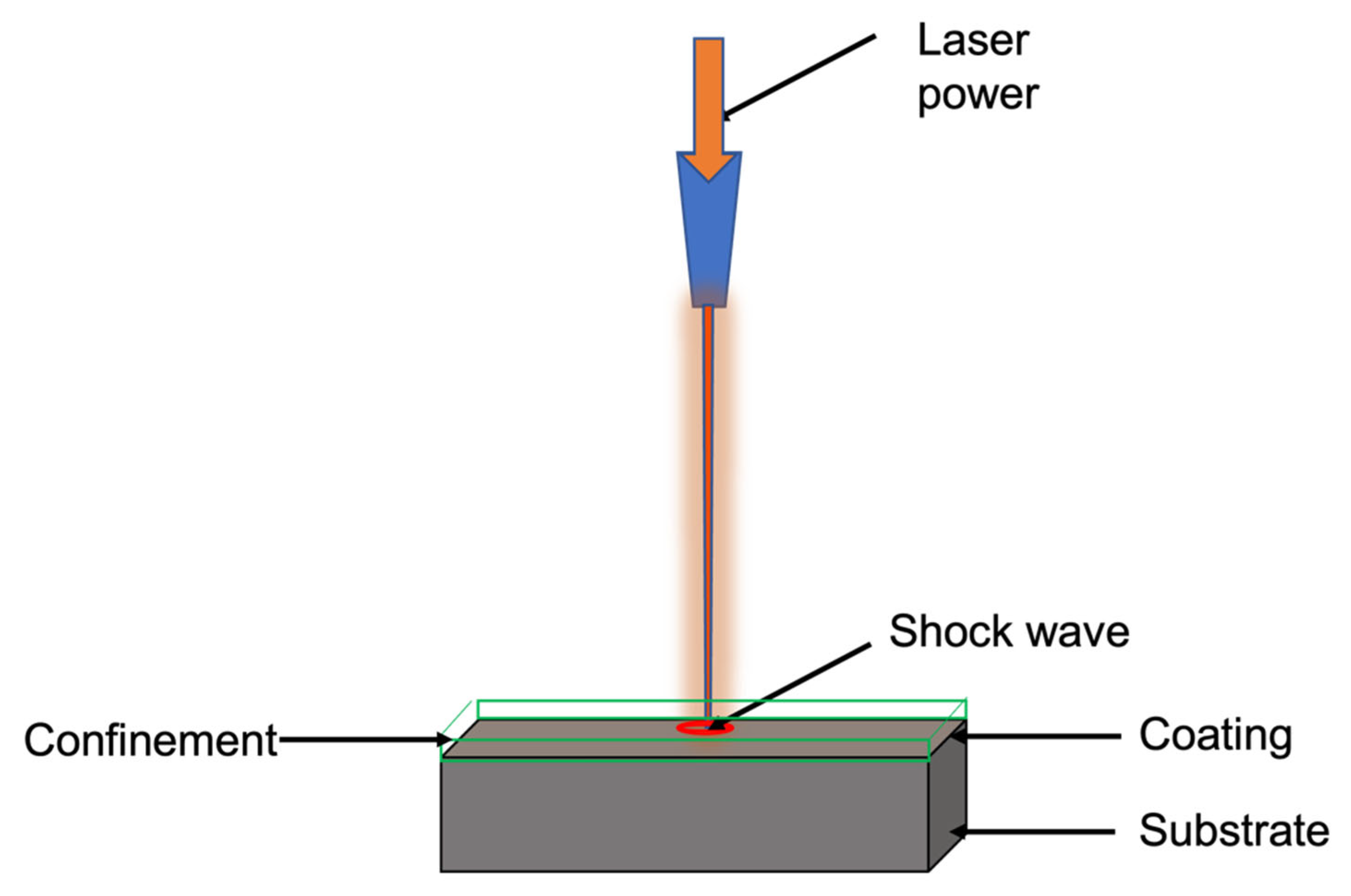
LSP fundamentally involves interacting a high-energy pulsed laser with coated substrate materials in a confinement medium. The surface of the substrate materials must be coated with sacrificial materials to absorb the intense energy and thereby prevent material ablation. The commonly used coating includes copper, zinc, aluminum, and black paint [58,59]. However, researchers reported that black coating has a superior ability to absorb the intense energy of the laser because it has a 100% absorption capability [60]. A confinement layer is applied on the top of ablative coating, which enhances the shock wave’s pressure. Water or BK7 glasses were commonly used as a confinement medium, preventing the plasma’s free expansion; hence, a high-pressure shock wave can be developed [61]. An increase in thickness or viscosity of the confinement layer up to a critical thickness can increase the pressure of the shock wave [62]. However, beyond the critical thickness, the water film scatters the laser beam and absorbs a large amount of plasma energy, reducing the shock wave’s peak pressure. Therefore, an appropriate coating and confinement material selection is essential, as these factors can influence the shock wave pressure and duration. When a high-intensity laser beam impinges on the coated substrate covered with confinement, it vaporizes ablative material and forms a laser-induced plasma. Since the coated substrate is surrounded by confinement, which hinders the free expansion of the plasma, this leads to the development of a high-pressure shock wave [63]. The pressure of the shock (order of GPa) is propagated into the substrate material and is subjected to very high plastic deformation (105/s–106/s) [64]. This leads to a work-hardened layer and CRS on the surface. These modifications on the specimen surface affect friction, wear, and corrosive behavior [65,66,67]. These inherent properties of LSP have pushed scholars to adopt LSP as a potential method to manipulate the tribology of interacting surfaces. The LSP schematic is shown in Figure 1.
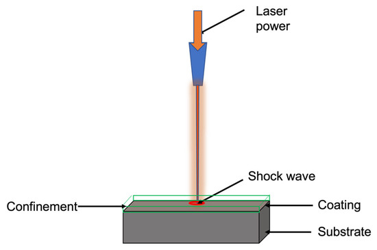
Figure 1.
Schematic of LSP.
While performing LSP, it is of utmost importance that the peak pressure of the shock wave should be higher than the dynamic yield strength of the material, also referred to as the Hugoniot elastic limit (HEL). The plastic deformation at this peak pressure causes dislocation multiplication, lattice distortion, and grain refinement, ultimately affecting the surface microstructure. As a result, this microstructural modification and surface hardening directly affect the friction, wear, corrosion, and fatigue behavior. Devaux et al. [68] developed an equation that can calculate the peak pressure of the shock wave, which is shown in Equation (1). Peak pressure is represented as P, reduced shock impedance as Z, and laser intensity as I. The reduced shock impedance is calculated using Equation (2) [69]. Z1 and Z2 represent the impedance of confinement material and substrate. is the efficiency of interaction.
As the shock wave pressure exceeds HEL, it interacts with the specimen surface and undergoes plastic deformation. This plastic deformation occurs 90 degrees to the surface. Along with that, the shock wave expands parallel to the surface. The pressure of the shock wave is attenuated while it propagates through the material. When the shock wave pressure is less than HEL, this leads to the development of an elastic deformation zone in the vicinity of the plastically deformed zone. The plastic deformation zone is subject to the reaction force due to elastic deformation, which leads to CRS development on the substrate [29,36]. According to Johnson et al. [70], the HEL limit can be correlated with the Poisson ratio and dynamic yield strength () of the material and is indicated in Equation (3). The plastic deformation () during LSP is represented in Equation (4) [71].
where are the Lame’s coefficient.
The grain refinement due to LSP depends on several parameters, and the grain refinement mechanism depends on the type of materials. Grain refinement due to plastic deformation depends on the materials’ stacking fault energy (SFE). The RCS and grain refinement are the primary reasons for surface hardening and surface topographical changes during LSP. These factors affect the substrate material’s friction, wear, and corrosion behavior. The following section discusses the beneficial role of LSP on steels, which are used for diverse applications.
3. Microstructural Evolution of LSPed Steels
During LSP, a high-energy laser beam bombards the substrate surface, causing the creation of high-power-density (GW), high-pressure (GPa), and short-duration (ns) shock waves [72,73]. During this interaction, the temperature of the substrate increases. Due to the combined effect of high-temperature and high-pressure shock waves and their modifying effect on the microstructure near the surface, properties such as surface hardness, corrosion, and wear resistance are improved [74]. Microstructural evolution in steels during LSP can be discussed in two sections: microstructure changes in plain carbon steels and changes in alloy steels, specifically in austenitic stainless steels. The effects of the high-energy laser beam on the material, deformation behavior, phases involved, and final phases are different in these two groups of materials.
3.1. Effect of LSP on Plain Carbon Steels
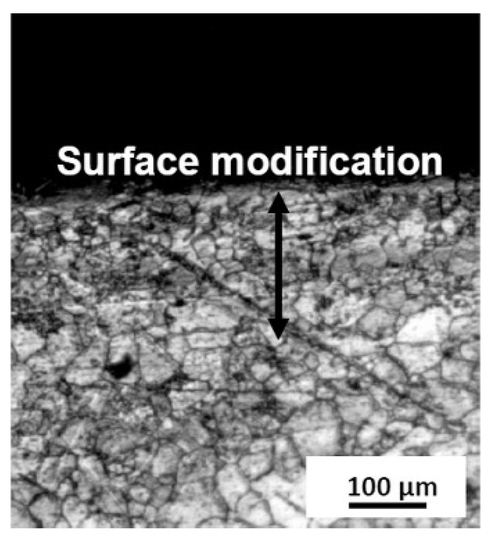
The effect of LSP on microstructural change in plain carbon steel is a function of the carbon content in it or the type of carbon steel. Shadangi et al. [75] explored the effect of LSP on surface modification in interstitial free steel (C < 0.004%) with a thermos protective coating at the surface. They varied pulse energy (Nd: YAG laser, 7 ns duration, power density 108 W/cm2, spot diameter 5.60 mm) in the form of 170, 230, 290, and 340 mJ (processing time 5 min) and also at 230 mJ. The processing time was varied as 5, 10, 15, and 20 min, respectively. They noted a significant grain refinement in the surface due to LSP. At lower exposure times, they noted grain refinement up to about 300 μm depth from the peened surface (Figure 2). Using TEM studies, they reported an increase in dislocation density. With the increase in exposure duration, a marginal increase in the depth of grain refinement and also localized melting were reported.
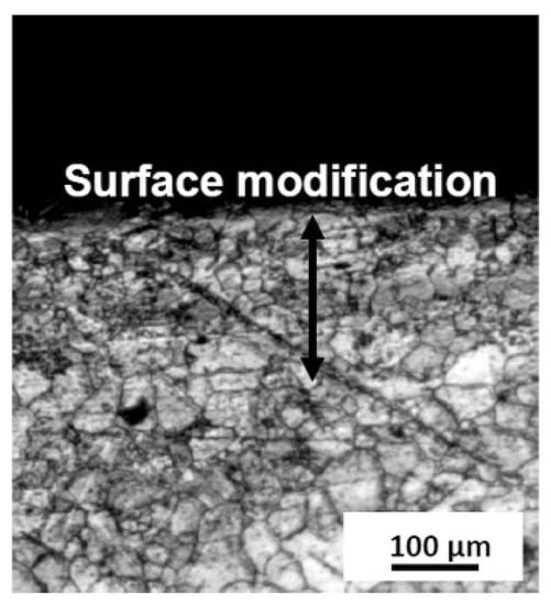
Figure 2.
Microstructure change on the surface of the IF steel upon LSP [75].
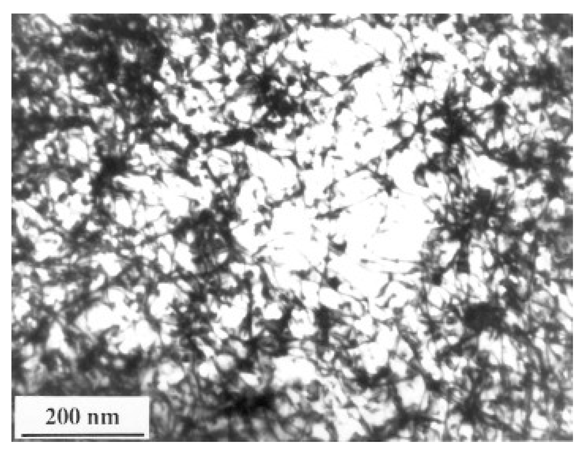
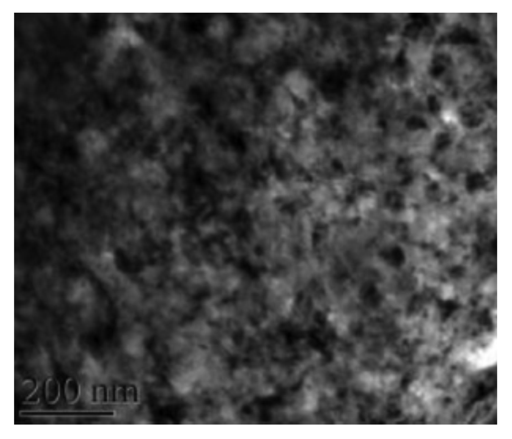
Chu et al. [76] demonstrated the effect of LSP on microstructure modification in low-carbon steel: SAE1010 (C < 0.04). For LSP, they used Nd: glass phosphate laser (pulse duration 600 ps, spot size 3.0 mm). The pulse energy was varied from 6 J to 111 J. Power density was in the range of 2.4 × 10¹² W/cm2 at a pulse energy of 100 J. The processing was done in a vacuum with black paint coverage. The TEM micrograph of the LSP-treated specimen presents a high density of dislocations (Figure 3). Using cross-sectional TEM, the authors demonstrated that a high density of dislocations is observed at a depth as much as 50 μm from the peened surface. Dense dislocation arrays are observed both at the grain interiors and near the grain boundaries. They indicated the creation of shock pressure waves in the range of <2 GPa and a time duration of less than 0.15 microseconds. They estimated the strain rate to be higher than (>106/s). They reported that the dislocations generated would not rearrange in the form of cell substructure because of the inability of the screw dislocations to cross-slip and move within the shot-peening period.
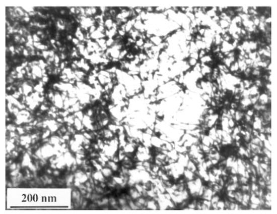
Figure 3.
TEM micrograph indicates an increase in the density of dislocations during LSP of carbon steel [76].
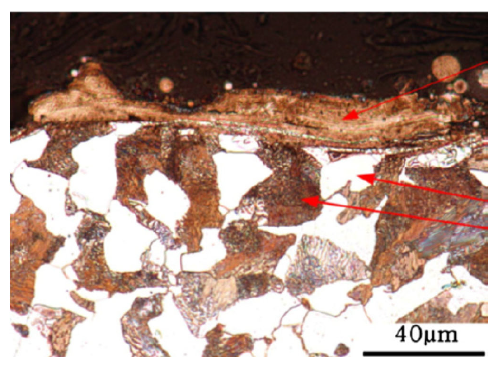
Hu et al. [77] demonstrated the influence of LSP on the AISI 1045 steel. For this purpose, they used a low-power laser operating at high frequencies. They used short pulses (1–50 ns) producing power > 1 GW/cm2 with underwater confinement. There was an opaque sacrificial coating on the steel surface. They reported a top layer consisting of martensite measuring about 20 μm (Figure 4). During the laser pulse, the top layer is heated up above A3 temperature and forms austenite. During self-quenching, this layer is converted into the martensite phase. No microstructural changes were observed in the subsurface region. Extensive dislocation generation during LSP of automobile steel with 0.55 wt% carbon steel was also reported by Pyre et al. [78].
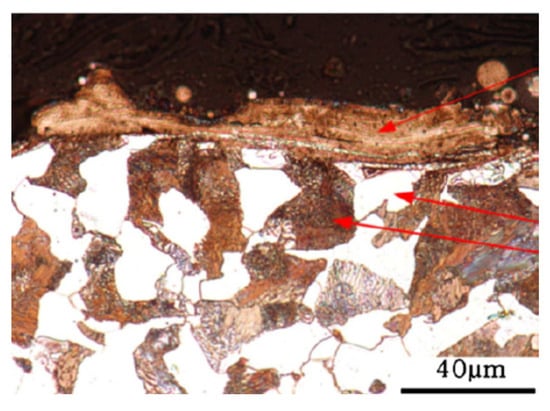
Figure 4.
Microstructure presents martensite formation at the surface during LSP of medium carbon steel [77].
Xiong et al. [79] treated the surface of eutectoid steel, which was earlier subjected to four passes of ECAP to create an ultrafine micro-duplex structure (ferrite + cementite). They reported that ultrahigh plastic strain created during LSP refines the microstructure further. They also noted that with an increase in the pulse energy, a part of the cementite is dissolved in the ferrite, causing an increase in the lattice parameter of the ferrite. The dissolution was attributed to the creation of dislocations and an increase in surface energy. The generation of many dislocations increases the dissolution of carbon atoms at the dislocation core, causing the dissolution of the tips of the cementite particles. When the deformation scale is larger, dynamic recrystallization occurs within the sub-grains, leading to a change in the grain character from sub-grain boundary to high-angle grain boundaries.
3.2. Effect of LSP on Alloy Steels
The microstructure changes in the alloy steels during LSP depend on the nature and quantity of the alloying elements. Prabhakaran and Kalainathan [38] explored the influence of WLSP without coating on phase transformations in low alloy steel, namely SAE 9254 (C 0.55, Si 1.4, Cr 0.7). The alloy was hardened at 900 °C and tempered at 400 °C to generate the ferrite-martensite microstructure. On LSP, it was noticed that the inter-lath-retained austenite was decomposed into carbides. Furthermore, the crystallite size was reduced from 50–60 nm to 31–50 nm. Ren et al. [80] reported the microstructural changes in 20Cr2Mn2Mo steel (C: 0.2, Si: 0.25, Mo: 1.5, Cr: 1.9, Mo: 0.25) after dual treatment of LSP and carbonitriding. They reported an increase in dislocation density and dislocation tangles. They explained that an increase in the dislocation density leads to dislocation rearrangements including cell wall structures. All features are expected to improve the barriers to dislocation movement. The surface had refinement to produce grains in the scale of 250 nm.
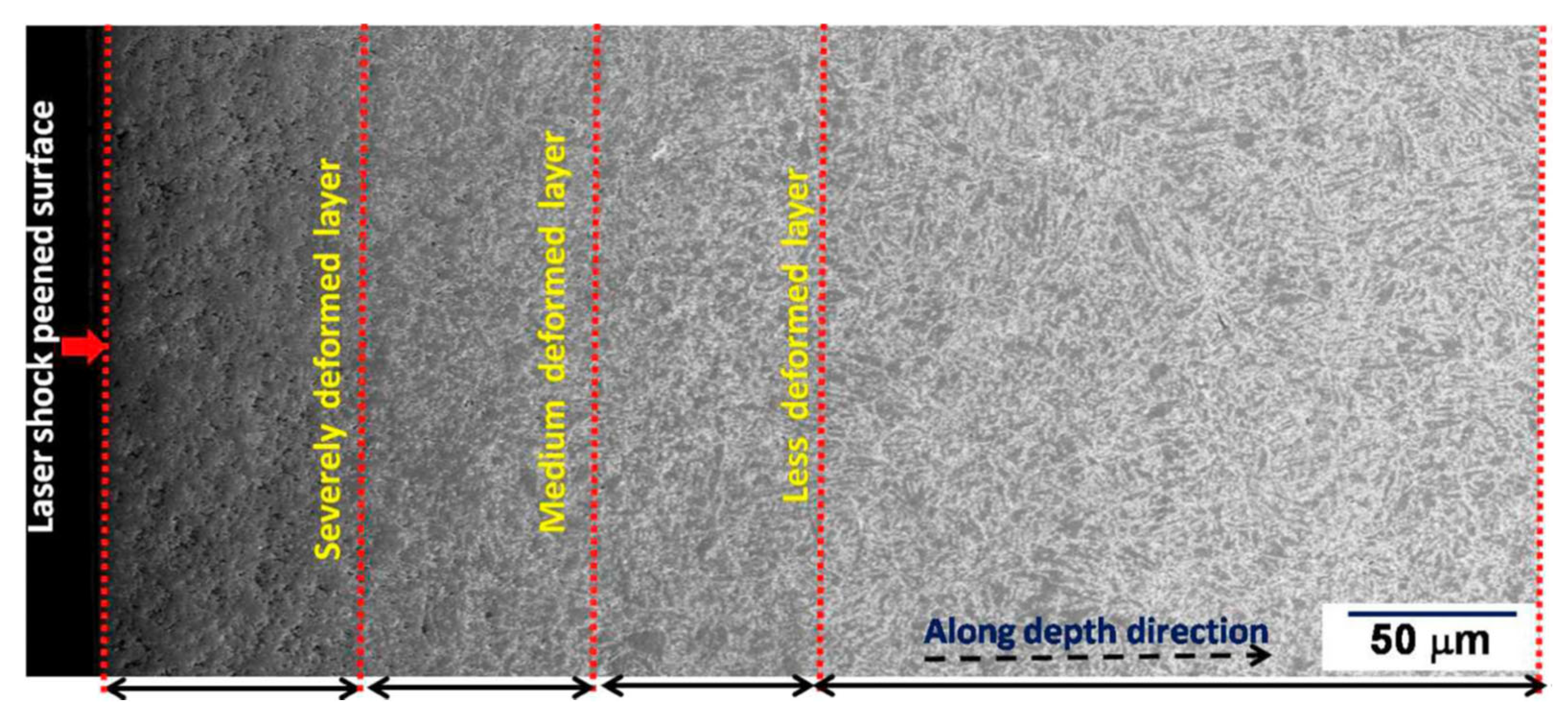
Rai et al. [81] exposed 9Cr-1Mo (P91) steel to single and multiple LSP. Before LSP, the steel was subjected to solution treatment at 1050 °C, followed by water quenching and finally tempering at 750 °C for 10 h. The initial microstructure had packets of lath martensite with prior austenite boundaries. The prior austenite size was about 20 μm, and the lath martensite had 1.2 μm width and 4.5 um length. Under single LSP, the energy density was varied as 3.9, 4.7, and 5.5 GW/cm2. Multiple (single, double, and triple) LSP was carried out with 3.9 GW/cm2. Upon multiple LSP, they noted three distinct layers along the depth within the affected region. The three layers are the severely deformed layer, medium-deformed layer, and less deformed layer. They are presented in Figure 5. In another investigation, Rai et al. [82] reported the formation of ultrafine grains of 300 ± 30 nm after a single pass and 105 ± 10 nm grains after three passes at the surface of the P91 steel, which had an initial grain size of 1200 ± 120 nm. Along similar lines, Lee et al. [83] reported the hardening of AISI H 13 tool steel due to LSP.
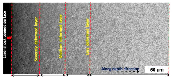
Figure 5.
The microstructure change can be viewed as different zones along the direction [81].
Similarly, Ren et al. [84] studied the effect of LSP on the ASTM:410 00Cr12 (C < 0.03, Cr 11–13). The treatment was done using 20 ns pulse duration, power density of 3.3 GW/cm2, and spot diameter of 6 mm. Peening was done at 400 °C, where the sample was fully austenitic. After LSP, a layer of deformation-induced martensite and micro twins was observed near the surface. However, no nanocrystalline layers were observed. There are many efforts to understand the effect of laser shock peening on stainless steel. Brandal and Yao [85] studied the microstructural changes in 304 SS due to exposure to LSP. They used an Nd-YAG laser with a pulse duration of 17 ns, a spot size of 1 mm, and a pulse energy of (125–300 μJ). They reported the formation of dislocation entanglement followed by dislocation cells, which delays hydrogen-induced austenite-to-martensite transformation. With the help of experiments and simulation, they proved that under low pressures (<1 GPa), the deformation level is relatively less and insufficient for a big change in the dislocation density. As the pressure increases, the fraction of dislocations in the cell increases, and at about 5 GPa, the ratio of dislocations at the cell wall and cell interior is close to 8. The material exhibited dislocation-induced martensite at higher pressure levels.
The work from Ye et al. [86] indicated the extensive formation of deformation-induced martensite during LSP. A similar effect was also reported by Nikitin and Altenberger [34]. They reported material behavior and overstrain rates in the range of 10–103/s. Under this condition, dislocation motions are activated, leading to martensitic change: the formation of ultrafine grains and nanocrystallites. On the increase in the strain rates (104 to 105/s), a high density of twin bundles with nanoscale dimension appears in the initial coarse grain. The effect of multiple LSP on AISI 304 was reported by Zhou et al. [87]. They reported surface nano crystallization and deformation-induced martensite using EBSD and TEM investigations. Nanostructures were on the scale of 50–300 nm after three LSP impacts. They also noted that the DIM forms only when energy exceeds 5.56 GPa. They proposed a mechanism for grain refinement during multiple LSP. LSP induces grain refinement under high strain-rate conditions (>10−7s−1). They concluded that LSP induces multidirectional mechanical twins and bands. The net effect is the extensive formation of grain subdivisions. LSP causes grain refinement through severe plastic deformation in the material along with the martensitic transformation. Gerald and Hallouin [88] reported the effect of very short pulses and very high laser intensity on 304 SS and reported that martensite embryos form at the intersection of deformation twins within the pressure range of 15–25 GPa. Figure 6 presents a micrograph where the nanocrystals of 30–500 nm formed on the surface of 304 SS after three series of LSP treatments. The presence of nanocrystallites with random orientations was confirmed with SAED patterns. The presence of twinning as a predominant deformation mechanism for grain refinement during SPD of 304SS was reported [89,90].
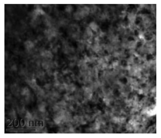
Figure 6.
Bright-field TEM indicating surface nanocrystallization in 304 SS after three LSP passes [87].
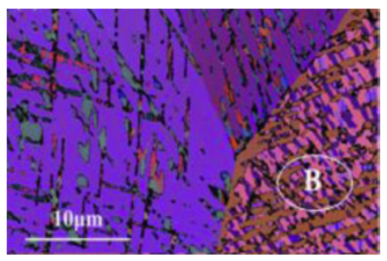
According to Zhou et al. [87], dislocation-induced martensite (DIM) is also a mechanism for grain refinement during LSP. This was supported by their observation of DIM after the first impact using 4.3 GW/cm2. Further, the extent of DIM increased with an increase in the number of passes. They proposed that multiple impacts provide more energy for plastic deformation, which in turn produces more martensite. Further, they used EBSD for characterizing deformation-induced microstructural features. The EBSD characterization indicates that the grain refinement after three passes of LSP is due to extensive mechanical twins and DIM, which are oriented in different directions. The EBSD micrograph on the surface of 304 SS subjected to three passes of LSP is shown in Figure 7.
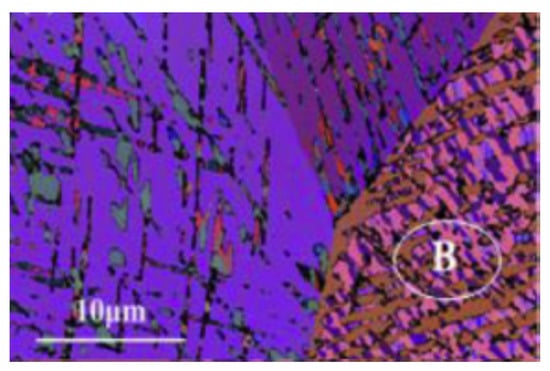
Figure 7.
Grain orientation after three LSP passes [87].
The microstructure indicates nanoscaled grains with a size of 50 nm to 300 nm. In the beginning, high-density dislocations are generated at the wavefronts caused by the shock waves. The shockwaves themselves are multidirectional [87]. They facilitate the movement of dislocations in different directions, causing dislocation–dislocation intersections and dislocation pileups. Due to dislocation pileup, stress increases, causing mechanical twins (when stress increases to a particular level). The boundaries of mechanical twins are generally parallel, and they divide the initial coarse grain into multiple strips. With further shock waves, the magnitude of distortion increases, forcing accumulated distortion to cross each other, forming intercrossed twins. During intercrossing, the deformation-induced martensite is nucleated. The XRD analysis also indicated the progress of martensite formation. The peak broadening in XRD also indicated the lattice deformation and increase in micro stress at the surface along with the grain refinement [87]. Ye et al. also explored the effect of cryogenic treatment during LSP [86]. The use of cryogenic conditions increases the extent of martensite formation under the same peening intensity. The microstructure after cryogenic treatment consists of high-density deformation twins, stacking faults, and a mixture of martensite and austenite. This innovative microstructure produced due to the combination of cryogenic treatment and LSP increases materials strength and microstructure stability under fatigue-loading conditions.
Another grade of stainless steel that is extensively studied using the LSP process is AISI 316L. Liu et al. [91] explored microstructural changes during the LSP of 316 L. Due to shock waves generated during LSP, dislocations are generated within the grain. Researchers also noted that the refinement in the grain structure (of 316 L) is due to the operation of slip-assisted deformations inside the crystal grains As the degree of plastic deformation increases, the high-density dislocation configurations rearrange themselves to form dislocation walls or cells within the grains. The formation of distinct regions of cell walls within a grain creates cell blocks. On these walls, additional dislocations pile up, converting cell walls into grain boundaries. When this is repeated, the grain size is be reduced considerably. Similar observations were also noted by Kalainathan et al. [92], Peyre et al. [93], and Hoppius et al. [94]. Further, Hoppius et al. [94] noted that the depth of the peening could be considerably increased using femtosecond lasers. These lasers can generate shock waves to the depth of 100–1000 GPa. The refinement of grains was also reported in 31 stainless-steel laser weld joints subjected to laser shock peening [91]. However, they reported that grains at certain locations from laser weldment tend to coarsen first and then become refined. This contrasts with that observed in some nonferrous metals such as Ni while performing LSP, as reported by Chen et al. [95].
LSP with multiple passes can generate a gradient in the scale of plastic deformation. LSP without coating and in a single pass can produce martensite phases and dense dislocation structures. These are limited to a shallow depth. These results are demonstrated in the case of AISI 321 subjected to LSP [96,97]. In addition to these microstructural features, shear bands and strain-induced martensite formation are also reported [98]. The formation of these microstructural features is affected by local strain rate, the presence of alloying elements, and local temperature. Chen et al. [96,99] reported that dislocations and their structure, shear bands, and strain-induced martensite affect their work hardening and influence ductility. The gradient in plastic strain and formation of nanotwins during multi-pass laser shock peening was reported in 321 steel by Karthik et al. [100]. Table 1 demonstrates the microstructural changes during laser shock peening.

Table 1.
Effect of LSP on microstructural features.
Overall, the microstructural changes during LSP depend on the strain rate involved in the peening experiments. When the strain rate is 101/s to 103/s, the austenite-to-martensite phase transformation occurs in the austenitic stainless steels. Dislocation activities are the major source of plastic deformation. If the strain rate is more than 105/s to 107/s, there is no martensitic phase transformation. Then, twinning is the primary source of plastic deformation. The increase in the intensity during LSP increases the formation of dislocation cells, walls, and tangles. This obviously enhances the mechanical properties. The grain refinement increases with laser intensity and the number of passes. SFE is another parameter that decides whether the type of plastic deformation during LSP is dislocation-dominant or twinning-dominant. The phase transformation during LSP also depends on the initial phase involved in the substrate.
4. Tribological Properties of LSPed Steels
Steels are predominantly used materials for structural applications. Hence, improvement in corrosion and wear resistance is important. Lim et al. [33] demonstrated that LSP on duplex stainless steel reduced the wear rate by 16%. They reported that LSP is a practical option to enhance the abrasion and corrosion resistance of desalination pumps. The authors attributed that surface hardening and grain refinement accounted for enhanced wear resistance. Yakimets et al. [65] conducted LSP experiments on rolling steel 100Cr6, revealing that the wear rate is reduced by 33%. This is attributed to the combined effect of surface hardening and CRS. The authors recommended that to enhance the longevity of 100Cr6, it is necessary to optimize the LSP parameters. Lu et al. [101] conducted multiple laser impacts on AISI 8620 steel, and their studies reported significant improvement in wear resistance. They observed a 46.7% increase in surface hardness with a single LSP impact, which was enhanced by 60% during three LSP impacts. The reported wear mechanism for the untreated specimens was oxidative wear, which contains bigger debris and oxides. However, for LSPed specimens, abrasive wear with grooves was observed due to micro plowing. The authors summarized that multiple laser impacts could significantly refine the grains on the surface.
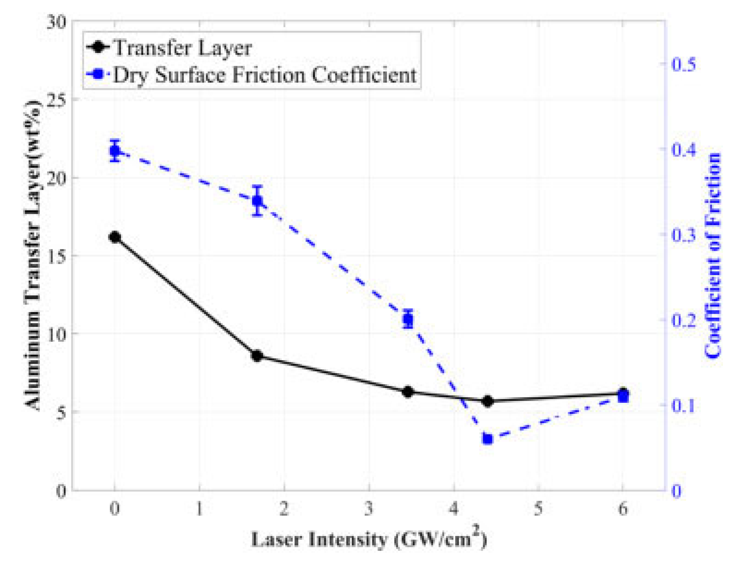
Siddaiah et al. [73] studied the influence of LSP process parameters on the tribological performance of the 1045 steels. In their experiments, the authors used four laser intensities (1.68 GW/cm2, 3.46 GW/cm2, 4.40 GW/cm2, and 6 GW/cm2) and compared the friction behavior and transfer layer formation. The authors reported a reduction in COF with an increase in laser intensity. The reported COF for untreated material is 0.4, and that for the LSPed specimen with a laser intensity of 4.40 GW/cm2 is 0.067. The COF was further increased to 0.112 for a laser intensity of 6 GW/cm2. The COF was reduced between 17.5% to 83.25% when intensity varied from 1.68 GW/cm2 to 4.40 GW/cm2 compared to the base material. Figure 8 represents the variation of COF and weight of the transfer layer formed during tribological testing of LSPed steels.
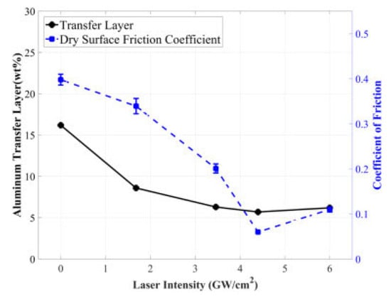
Figure 8.
LSP influence on COF and transfer layer [73].
The reduction in COF has been correlated to surface morphological changes. LSP causes deformation and restructuring of the surface asperities, which authors have explained using roughness amplitude parameters such as skewness and kurtosis. COF is reduced by 17.5% corresponding to a laser intensity of 1.68 GW/cm2. With the increase in laser intensity, the asperity size decreased, leading to a platykurtic surface with low sharpness. The 83.25% reduction in COF at 4.40 GW/cm2 is attributed to the smaller size of asperities Both the transfer layer and COF variation follow the same trend with increased laser intensity. For untreated substrate, the transfer layer is 17%, which decreases to 5.4% (approximately 83%) corresponding to a laser intensity of 4.4 GW/cm2. This is attributed to the reduction in shear stress because of the formation of small asperities at the interface between the counter material and substrate. LSP causes deformation and restructuring of the surface asperities, which authors have explained using roughness amplitude parameters such as skewness and kurtosis. COF is reduced by 17.5% corresponding to a laser intensity of 1.68 GW/cm2. With the increase in laser intensity, the asperity size decreases, leading to a platykurtic surface with low sharpness. The 83.25% reduction in COF at 4.40 GW/cm2 is attributed to the smaller size of asperities. Both the transfer layer and COF variation follow the same trend with increased laser intensity. For untreated substrate, the transfer layer is 17%, which decreases to 5.4% (approximately 83%) corresponding to a laser intensity of 4.4 GW/cm2.
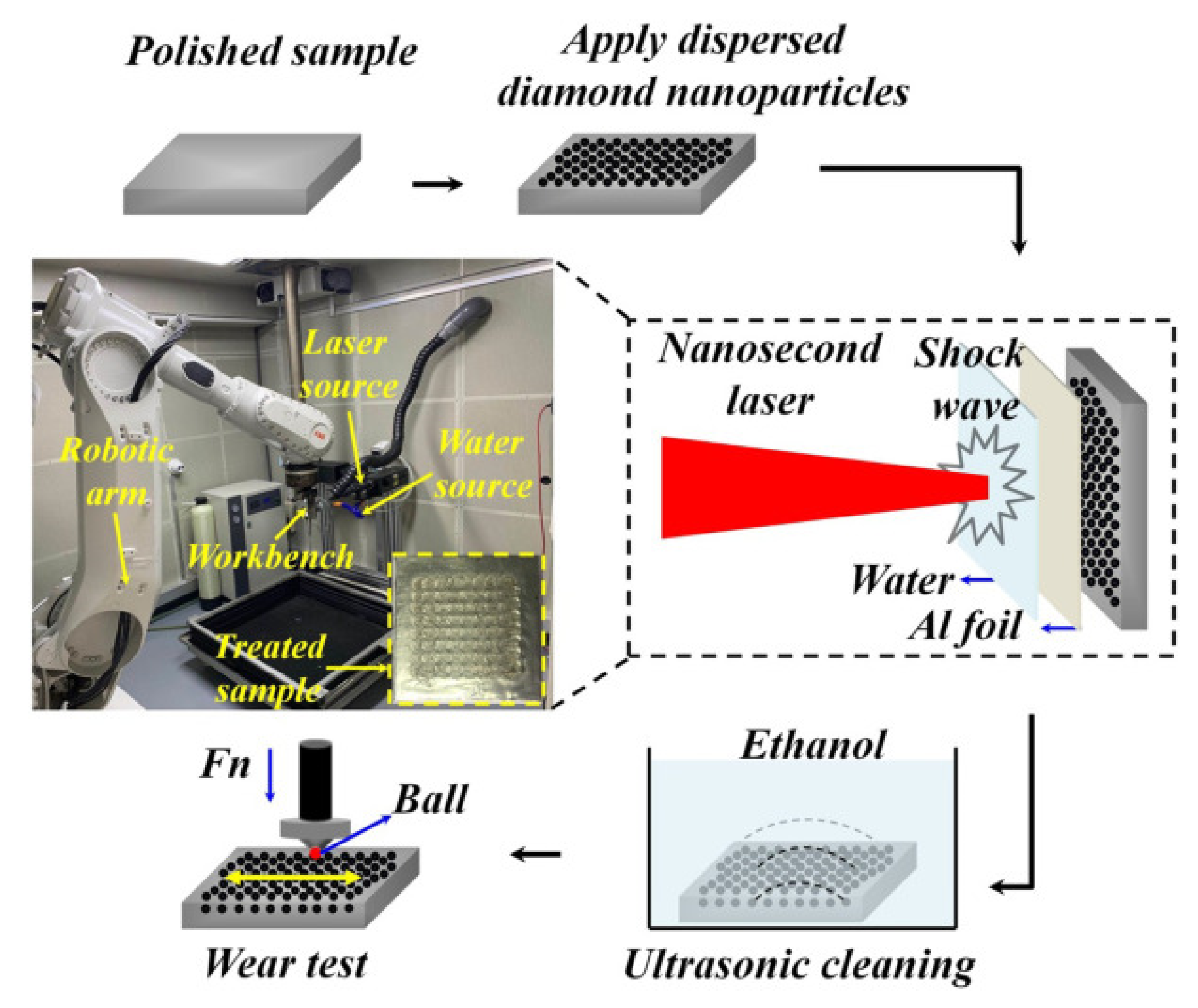
This is attributed to the reduction in shear stress because of the formation of small asperities at the interface between the counter material and substrate. When the laser intensity is increased to 6 GW/cm2, the transfer layer rises to 6.5%. The authors observed smaller asperities with sharp peaks at this laser intensity, increasing the plowing component of friction. Lu et al. [102] performed implantation of diamond nanoparticles on 20Cr2Ni4A alloy steel using LSP and studied the wear resistance. They used aluminum foil and water as a coating material and confinement medium. The experimental setup for the diamond nanoparticle implantation using LSP is shown in Figure 9. In their experiments, the authors used four laser energies such, namely 4 J, 6 J, 8 J, and 10 J with and without nanoparticle implantation, and the obtained results were compared with untreated material.
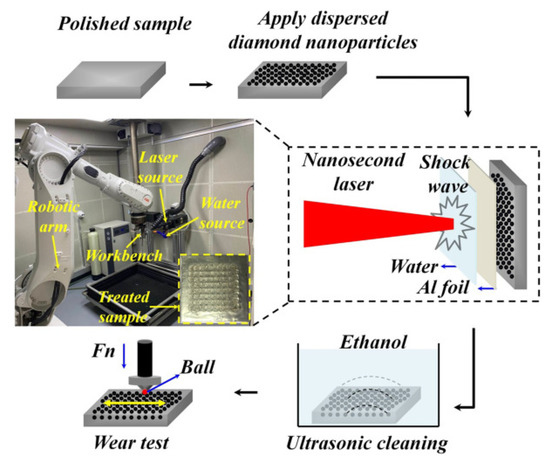
Figure 9.
The experimental setup for the diamond nanoparticle implantation using LSP [102].
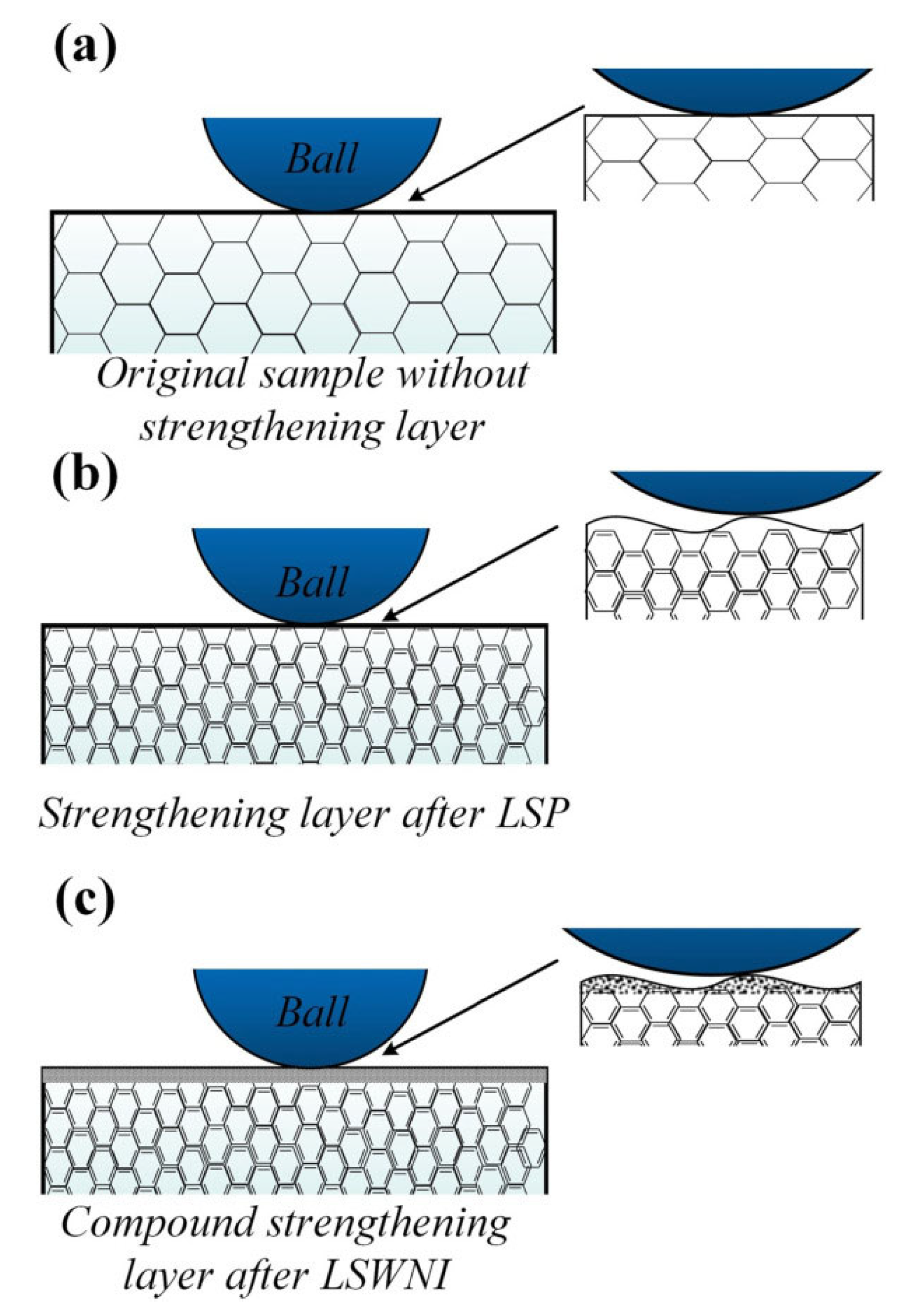
The wear studies revealed that diamond nanoparticle impanation using LSP techniques enhanced the lubrication properties and changed the wear mechanism from abrasive to a combination of adhesive and abrasive wear. The wear model is shown in Figure 10.
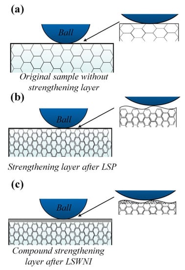
Figure 10.
Wear model (a) untreated specimen, (b) LSPed specimens, and (c) diamond nanoparticle implanted using LSP specimens [102].
The specimen treated with 10 J laser energy without nanoparticle implantation showed a 43.75% reduction in mass loss during wear studies. This is primarily attributed to the enhancement in surface hardness that hindered the creation and propagation of microcracks. Similar results were reported in the case of COF. Maximum reduction in COF was observed with the laser energy of 10 J during nanoparticles’ implantation in the surface. Nanoparticle implantation with laser energy of 10 J on the specimen reduced the COF to 0.31 compared to the untreated specimen. The authors explained the enhancement in wear resistance due to LSP and nanoparticle implantation using the wear model. In the case of untreated materials, the wear occurs due to low surface hardness, leading to deep furrows. However, after implementing LSP, wear resistance increases because of surface strengthening. With nanoparticle implantation, a super-hard surface is formed, reducing wear resistance. Furthermore, the nanoparticle provides a self-lubricating capability, which reduces the wear mass loss. Molian et al. [103] showed similar results while implanting nanodiamond powder using LSP aluminum 319-T6 alloy. This produced a strong and wear-resistant coating on the surface. Zhu et al. [104] performed tribological studies on selective laser-melted (SLM) stainless steel and reported an enhanced tribological performance. This is predominantly due to the refined grains developed during the SLM. They demonstrated the mechanism in which they discussed the effect of pores and grain size on friction and wear behavior. Similarly, Alvi et al. [105] performed LSP on SLMed SS316, and they studied the friction and wear at high temperatures and compared them with conventional SS316. The authors observed significant wear reduction in SLMed components at 300 °C and 400 °C, which they attributed to the stable hierarchical microstructure, cellular sub-grains, and stable oxide glaze. Zheng et al. [106] conducted LSP experiments on ASS304 and demonstrated large-area micro dents on the surface. They attributed this to microplastic deformation occurring during the Process, generating a large area of micro dents with uniform depth. They reported reduction in friction and wear rate at lower loads. This is attributed to the improved surface hardness and presence of RCS.
Aldajah et al. [107] performed LSP on 1080 carbon steel and compared the tribological performance with another surface modification technique named laser glazing. Laser glazing (LG) involves the interaction of a high-power laser with a substrate that melts the surface of the substrate and furthers it subject to a rapid cooling process in which resolidification occurs. This changes the surface microstructure, which provides superior surface properties. The authors considered four different specimens: an LSPed one, an LGed one, LSP followed by LG, and LG followed by LSP. They adopted a pin-on-disc setup, and the specimens were slide against alumina. All four cases reduced friction, and a 40% reduction in friction was observed for the specimen subjected to LSP first, followed by LG. In addition, the authors reported that the wear rate during LG is significantly lower than LSP. They found this to be because the reduction in wear rate is predominantly due to the near-surface microstructural changes. Table 2 demonstrates some important observations during LSP on various engineering materials.

Table 2.
Effect of LSP on tribological and other mechanical properties.
In summary, all the tribological studies discussed in the paper regarding the LSP show that LSP is a potential and powerful surface modification technique. LSP induces severe plastic deformation that alters near-surface microstructure and RCS, ultimately providing superior surface mechanical properties. This helps to reduce the failure originating from a surface, such as corrosion, wear, and fatigue. LSP is an appreciated boon to various industries. However, obtaining desired properties in particular materials during LSP depends on the type of materials, severe plastic deformation, crystal structure, strain rate, and stacking fault energy. Additionally, with an increase in laser intensity and the number of passes, the surface roughness increases, which can be deleterious at higher values. Hence, it is always a trade-off between roughness and other mechanical properties.
5. Corrosion Properties
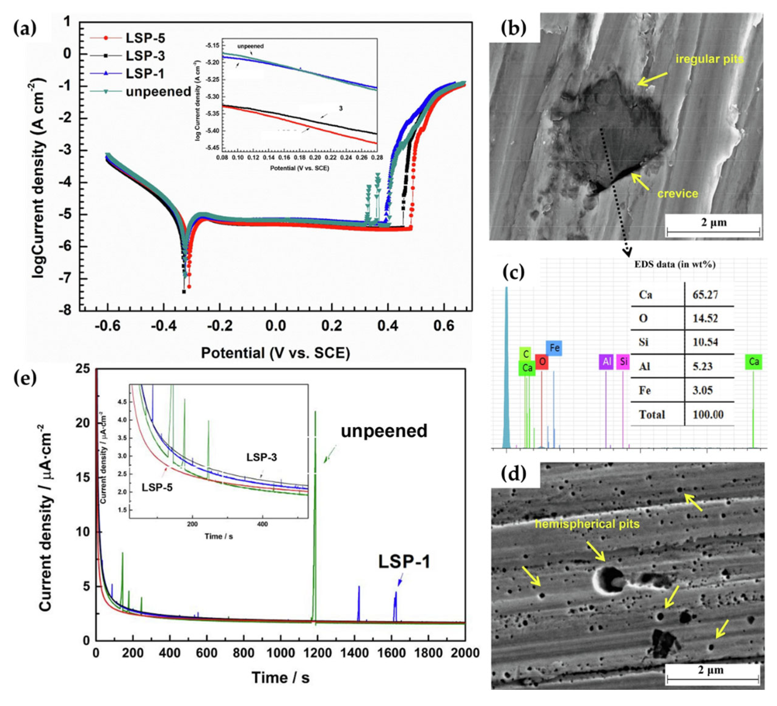
Considering the metallurgical augmentations induced by LSP, the electrochemical performance of LSP steels has been reported to be largely influenced [33,93,109]. This phenomenon is due to change in microstructural characteristics, surface roughness, elemental redistribution, and residual stresses induced by the shock wave process [110]. Although some of these factors may influence corrosion resistance more than others, it is universally agreed that the metastable pitting rate and formation of the Cr2O3 passive film are improved as a byproduct of LSP. This was observed in the work of Guan et al. [111], in which 304 L stainless steel was subjected to a massive LSP process, of which the power density of the LSP shockwave was set at 6.4 GW/cm2. By varying the number of impacts (between one, three, and five times), the metastable pitting nucleation rate and pitting morphology were investigated and is shown in Figure 11.
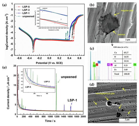
Figure 11.
The (a) potentiodynamic polarization curves and pitting morphologies of (b) bare-304 L steel substrate (with its EDS analysis within the pit (c)) and (d) its LSP counterpart at a repeated impact rate of five. Additionally, the (e) potentiostatic polarization curves illustrate their pitting frequencies [111].
Mechanistically, these findings are attributed to the diffusion rates of Cr as well as the newly formed compressive stresses along the surface of the steel specimens post LSP. As it is well known, the multiplication of dislocation tangles induced by peening allows for the nucleation of a more compact and robust microstructure. Having a higher degree of grain boundaries, the Cr elements along the microstructure are increasingly active, which allows for their rapid diffusion into thicker Cr2O3 films beneath the existing Fe3O4 and FeO films. These findings imply that the transition from metastable pitting to stable pitting is effectively reduced, which can improve the longevity of steel substrates. On the other hand, the compressive stress field induced by peening also suggests that existing inclusions are effectively eliminated. This implies that a greater uniform oxide film can exist, which can prevent specific locations from being ruptured and lessen the cumulative corrosion rate. Similar findings were also observed in the various works of Lu et al. [110,112]. Their works further expand these ideas by elucidating the specific electrochemical reactions that occur during PDP testing, the formation of pitting over long periods of immersion time, and the influence of atomic phase structure on the tendencies of localized corrosion [112]. A brief overview of their supporting findings is shown in Figure 12.
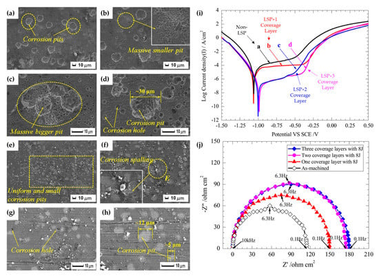
Figure 12.
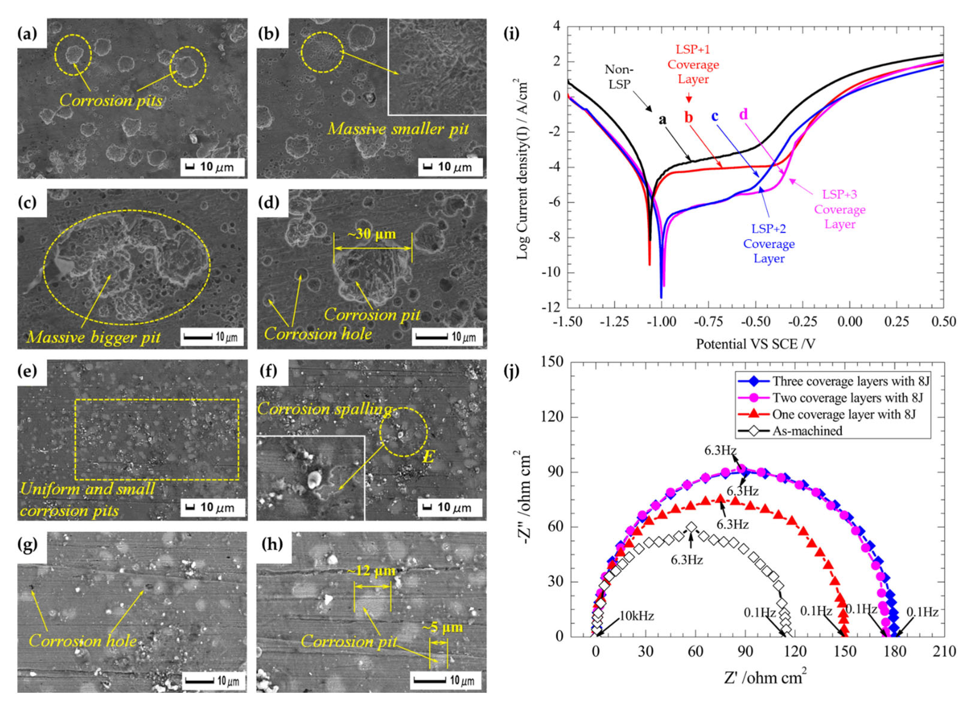
The corrosion pit morphology of high-temperature-immersed (a–d) AISI 4145 medium carbon steel and (e–h) its LSP counterpart at 200 h. Additionally, their electrochemical characteristics under (i) PDP and (j) EIS conditions (displaying a Nyquist plot) [112].
When LSPed AISI 4145 steel is subjected to immersed conditions (Figure 12a–h), it was found that the pitting morphologies were significantly altered. Under LSP conditions (Figure 12e–h), the corrosion pits not only appeared to be smaller in diameter, but their interactions were practically non-existent, unlike the non-LSP surface (Figure 12a–d). These findings were linked to the principle of SCC, as with the propagation crack growth rate of steels under high temperature, chloride-containing environments are exacerbated due to the rupturing of the passive film along the surface. In some cases, the passive film can re-passivate; however, this factor is dependent on the microstructural characteristics of the steel specimen. With the refined microstructure under LSP conditions, this likelihood is greatly increased. Following these findings, the electrochemical reactions were described as the following:
This indicates that the primary corrosion product induced from immersion testing was primarily Fe2O3. Under PDP (Figure 12i) and electrochemical impedance spectroscopy (EIS) (Figure 12j) conditions, similar findings were also concluded as the pitting potential (VSCE) was decreased, and the radius of the capacitive impedance loop (from the Nyquist plot) was increased. From a phase standpoint, the dual-layer lamellar-like structure of the ferrite and cementite phases (also commonly referred to as pearlite) was effectively broken into smaller, more segregated sections with block-like carbides along the ferrite grain boundaries. Typically, with a strip-like lamellar structure, the corrosion rate (and the tendency for localized pitting corrosion) is greater due to the galvanic-like cells that occur between the ferrite and cementite phases [113]. For the ferrite phase, the charge transfer process is primarily anodic, as it tends to dissolve preferentially compared to cementite, as it is insoluble (thus acting as a cathode) [114]. Having this phase broken up diminishes these micro-galvanic cells, which in turn reduces the cumulative pitting that occurs in electrochemical environments. Having this fundamental understanding of the corrosion resistance of LSP steels, many have explored outside of the standard testing conditions of LSP to create a simpler base of the application.
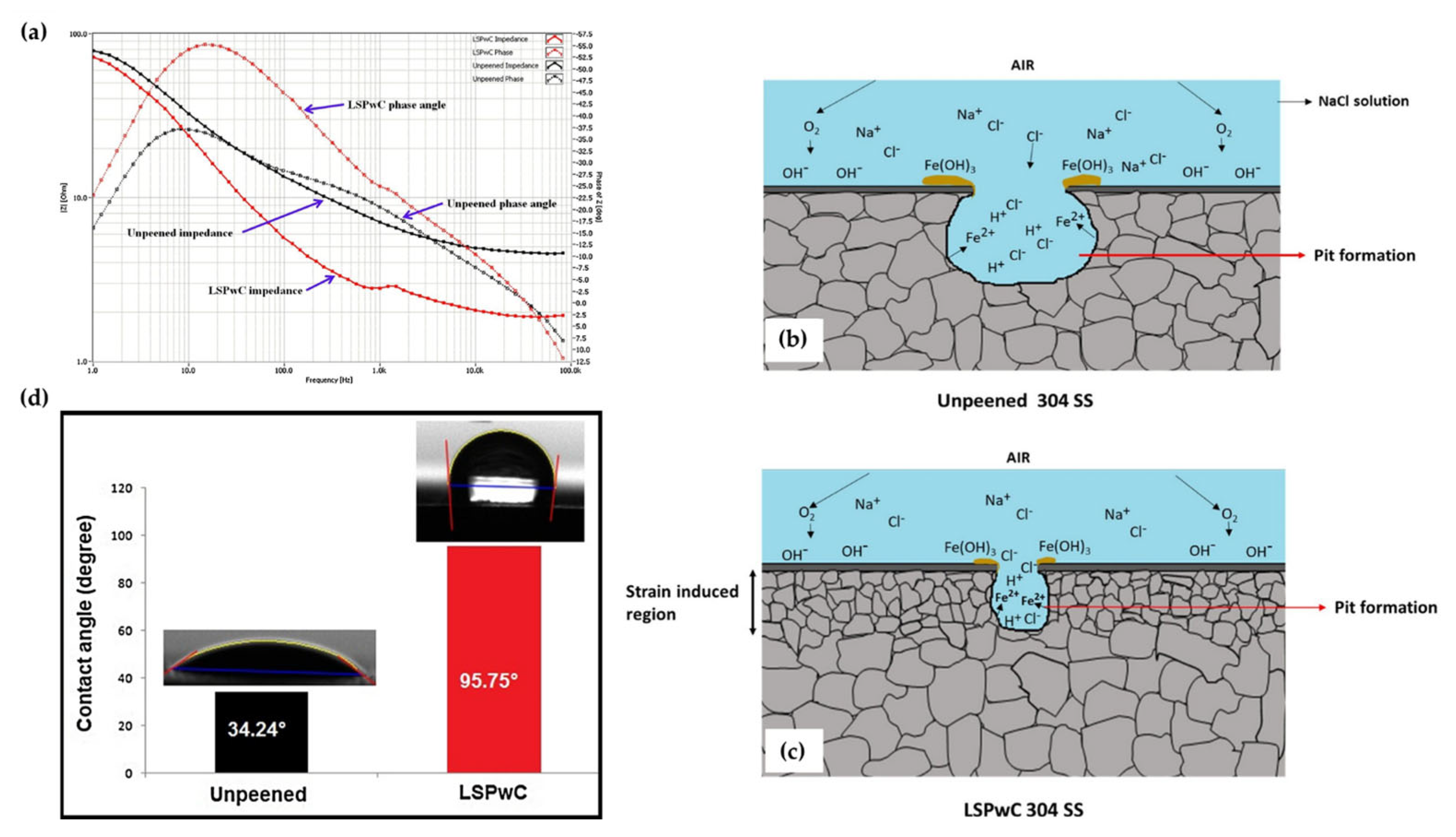
This was shown in the work of Prabhakaran et al. [115], in which the pitting corrosion characteristics of γ-phase 304 stainless steel were studied after laser shock peening without coating (LSPwC) was applied. Similar to the aforementioned works, the strain-induced region (containing compressive stress fields and a refined microstructure) enabled the formation of a significantly more robust oxide film along the surface. These results were reflected by the Bode phase angle and impedance plots shown in Figure 13a, of which the LSPwC-treated steel exhibited the highest impedance modulus at high frequencies, indicating that the charge-transfer process was hindered due to the stable passive film formation. For reference, the pitting corrosion mechanism for both the peened and unpeened specimens is illustrated in Figure 13b,c. Interestingly, the authors expanded on the idea of surface wettability to the roughness characteristics of the LSPwC corrosion resistance. With many authors largely neglect this variable (as it is largely believed that it has a minuscule role in corrosion resistance compared to factors such as microstructural refinement and compressive stresses), the authors of this work found that the higher surface roughness enabled a hydrophobic surface compared to the unpeened hydrophilic surface (as shown in Figure 13d). The authors attributed this transition to the change in surface free energy enabled by the peening process. Having an uneven surface roughness, the oxide layer formed altered the material-to-water interactions. From a corrosion point of view, the hydrophobic surface characteristics help repel the contacting water molecules from penetrating the surface, which can cause pitting corrosion. Altogether, this work provides a novel insight into the corrosion mechanisms of steel.
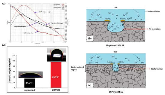
Figure 13.
The (a) Bode phase and impedance plots as associated pitting corrosion mechanism for (b) non-LSPwC and (c) LSPwC steel. Additionally, (d) the corresponding wettability measurements for these specimens [115].
Outside of pitting corrosion resistance, corrosion fatigue cracking (CFC) of steel has also seen noticeable improvement due to LSP. This was observed in the work of Wang et al. [116], in which the CFC of AISI 420 martensitic stainless steel (MSS) was improved due to massive laser-shock-peening treatment (MLSPT). For reference, the differentiation between traditional LSP and MLSPT is the amount of overlapped peens that occur on the surface. In the case of this work, a laser pulse energy of 3.6 J was applied to the surface. Following, this, the second layer of peens at 5.6 J was applied. Lastly, the third layer of 7.6 J laser pulse energy was applied. Typically, under cyclic loading conditions (in NaCl solution), a protective oxide film is initiated to protect the surface from fracturing. With the presence of Cr-carbides along the material, the Cr-depleted zones result in the oxide film rupturing, of which the persistent slip bands (PSBs) quickly dissolve, resulting in the formation of localized corrosion pits. These locations act as crack-sensitive sites that can initiate early fatigue cracking. When subjected to MLSPT, the Cr-carbides are effectively fragmented, which then results in a reduction in stress concentration due to the more even, passive film that is formed on the surface. Similarly, the refined microstructure also acts as a barrier to prevent crack growth in chloride-rich solutions due to the nano-sized carbide precipitates. Altogether, LSP is shown to be a useful technique for improving the corrosion resistance of steel materials. Table 3 represents the corrosion properties of LSPed steels.

Table 3.
Corrosion properties of LS’ed steels.
In summary, the corrosion properties after LSP strongly depends on the surface roughness. The surface roughness increases with laser intensity and the number of passes, which is a deleterious factor. The increase in surface roughness beyond a point affects the corrosion performance. Many authors showed that at high intensity and the number of passes, the corrosion current increases, and pitting resistance decreases.
6. Recent Advances
Scholars always searched for various alternatives to LSP based on the field of application. However, the application of sacrificial coating for complex geometries is a challenging task, which significantly hinders the LSP efficiency. Maawad et al. [122] demonstrated laser shock peening without coating (LPwC). This technique can induce in-depth RCS of the substrate material. Sakino et al. [123] performed LPwC on 490 MPa laser-welded steels. The authors summarized that LSP changes the RTS to RCS, and the maximum change in residual stress was observed on the weld toe. The authors also mentioned an increase in the fatigue life of welded joints after LSP. Similarly, Kalinatahn et al. [92] performed LPwC on SS316 L. They reported a significant enhancement in corrosion resistance. The corrosion current decreased, and corrosion potentials were shifted more anodically with increased laser intensity, showing less susceptibility of the LPwC specimen to corrosion. The surface stress improved from 12 MPa to a maximum of −273 MPa.
Altenberger et al. [124] revealed the residual stress relaxation in LSP-treated 304 SS and Ti64 alloy operated at a temperature range of 550–600 °C. To avoid residual stress relaxation at high temperatures, a new peening method called WLSP was introduced. Ye et al. [37] demonstrated WLSP on AISI 4140 steel. The authors reported that WLSP possesses the advantages of dynamic precipitation and dynamic strain aging. In addition, they concluded that WLSP-treated substrate has better fatigue properties than the LSP substrate. The DSA helped to increase the dislocation density and stabilized the dislocation structure by pinning mobile dislocations. Moreover, ultra-fine precipitates aid in stabilizing the microstructure and retaining the residual stress. Prabhakaran and Kalainathan [38] performed WLSP without coating on low-alloy steel. The authors reported austenitic-to-martensitic transformation during WLSP and superior fatigue performance. Meng et al. [125] showed improvement in damping property during WLSP.
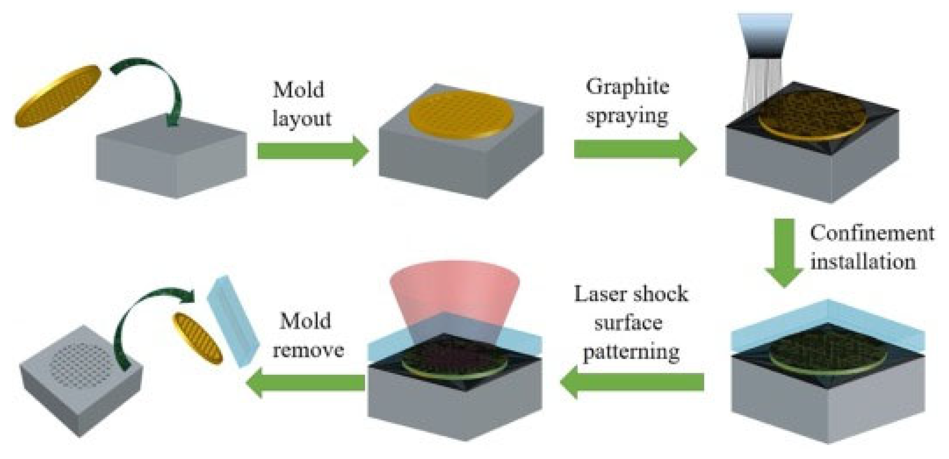
Similarly, scholars performed LSP at cryogenic temperature, and they named the process cryogenic laser shock peening (CLSP). Li et al. [35] performed CLSP on TC6 alloy and reported increased dislocation density and deformation twins. [94]. Ye et al. [86] demonstrated deformation-induced martensite and nano twins during the CLSP of SS 304. The authors attributed superior fatigue performance to the higher surface hardness and stabilized microstructure. Femtosecond laser shock peening (fs-LSP) is a new development in LSP in which lower pulse energy can enhance surface mechanical properties compared to conventional LSP. Li et al. [126] showed the effect of confining the medium and protective layer during fs-LSP of SS 304. The fs-LSP treatment on 304 SS without the confining medium and protective coating showed a 45% improvement in hardness. The shock wave propagation distance is less than the confining medium’s thickness when water is used as the confining medium. Due to water ionization, about 98% of laser energy is absorbed, leading to a poor peening effect. Although the surface roughness increases when peening is conducted in the air without coating, this is acceptable for many applications because of the lower amount of affected area. Laser-based forming (LPF) is another development in LSP. LPF can be adopted as a potential technique for bending, shaping, and forming sheet metals in industries. Electro pulsing-assisted laser shock preening (EP-LSP) is another innovation to enhance the plasticity of the metals [127]. For low-plasticity metals, it is challenging to induce the RCS. To induce RCS, the substrate is subjected to resistive heating along with high-strain-rate plastic deformation. Mao et al. [9] introduced a novel laser shock surface-patterning (LSSP) technique. The authors integrated the surface-hardening and surface-texturing effect using this technique. This is considered one of the efficient methods of surface modification that has superior control over the surface roughness and thickness of the plastically deformed layer. The LSSP schematic is shown in Figure 14. This method uses a special kind of micro mold that is kept on the surface to be peened.
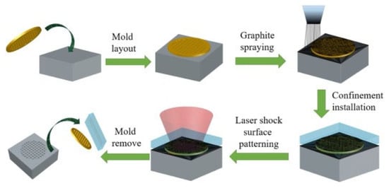
Figure 14.
Schematic of LSSP [9].
A graphite coating is used as the ablative material. A confinement layer is applied on the surface to enhance the pressure of the shock wave produced during the free expansion of laser-induced plasma. As a result, anti-skew surfaces are formed during the laser-matter interaction, consisting of an array of micro indentations. During this laser interaction with the micro mold substrate, the micro mold serves as a mask that provides the cushioning effect. As a result, LSSP can control surface roughness to a great extent.
7. Applications
LSP techniques are widely adopted for diverse applications in the automotive, aerospace, biomedical, marine, and nuclear industries. Among aerospace industries, the primary consideration is the enhancement of fatigue properties. LSP techniques are implemented in both passenger and military aircraft. LSP is employed as a post-processing method for landing gears, aircraft engines, shafts, valves, compressors, and turbine blades for aerospace applications. Engine turbine blades were subjected to cyclic loading during the operation; hence, it is essential to prevent failure arising due to fatigue. Hammersley et al. [128] reported an enhancement in fatigue properties after LSP. They observed two-fold increases in fatigue properties with the help of LSP. Scholars also showed the application of LSP for joining thin wall sections for aero engine applications. Shi et al. [129] showed the effect of LSP on the microstructural and mechanical properties of thin-wall welded titanium alloys. The authors summarized that LSP could successfully enhance the inferior fatigue properties of the weld joint. The enhanced fatigue properties were attributed to RCS and grain refinement. Additive manufacturing (AM) techniques using LSP as a post-processing method to enhance surface mechanical properties. The porosity and tensile stresses developed during AM can cause inferior properties, which can be successfully eliminated using LSP. Hack et al. [130] used LSP as a post-processing method for AMed specimens to enhance fatigue performance. They suggested that LSP is a potential post-processing method to enhance the fatigue life of AMed components. Each layer can be treated with LSP during the successive pass of AM, which is called the 3D LSP technique. This process integrates selective laser melting (SLM) and LSP techniques. Superior enhancement in properties of AMed components can be obtained from 3D LSP techniques. Among automotive industries, LSP can be used to enhance the service life of mechanical components. Ganesh et al. [50] studied LSP on leaf springs and showed improvement in fatigue life attributed to the superior surface quality and absence of peening-induced defects. Prabhakaran et al. [131] showed the enhancement in mechanical properties during LSP of ultrafine bainitic steels for automotive and structural applications. There was a reported five-fold increase in fatigue properties compared to the untreated sample. LSP techniques are used to post-process weld joints to prevent tensile stress.
LSP techniques are widely adopted to prevent SCC issues in the weld joints of dry storage canisters used for nuclear applications. Wei et al. [119] performed LSP experiments on AISI 304 SS and studied SCC in acid chloride solutions. The authors observed the deformation twins and grain refinement. The authors accounted for grain refinement and RCS as potential factors for enhancing the SCC resistance. Due to refined grains grain refinement generates more grain boundaries, which can promote the Cr diffusion to the material surface and form a homogenous, dense, passive film rich in Cr, which can enhance the corrosion resistance. Moreover, a high number of grain boundaries due to grain refinement can prevent microcrack initiation and propagation. Similarly, Lu et al. [132] showed increased SCC resistance during an accelerated corrosion test in boiling magnesium chloride.
Overall, these studies reveal that LSP is a potential surface modification technique that can enhance the service life of engineering materials operating in extreme conditions. The RCS and surface hardening during LSP can improve corrosion resistance and tribological properties. In the future, combination techniques will come into practice. Scholars can adopt different surface modification techniques to obtain the desired properties. However, parameter selection is a cumbersome task for obtaining optimum properties in a particular material. In the future, artificial-intelligence-based systems will be integrated with LSP and can optimize the parameters easily instead of using trial-and-error experiments.
8. Conclusions
This review paper elucidates a potential post-processing method named “LSP” for superior tribological and corrosion properties. High friction and wear of mechanical components for industrial applications cause severe economic loss, which can be carefully avoided by implementing LSP. The LSP-based SPD technique possesses good controllability and flexibility, inducing in-depth RCS on the component surface. Further, this review discusses the mechanism of LSP, the introduction of RCS, peak pressure development, and the grain refinement mechanism. Here, a comprehensive discussion on the current state-of-the-art LSP for enhanced tribological properties and corrosion performance of low-carbon and alloy steels was explored. Furthermore, this review considers the influence of LSP on COF, wear rate, corrosion, fatigue, and hardness of various metals and alloys. Recent advancements in LSP techniques were reported. Finally, various applications of LSP in automotive, aerospace, nuclear, marine, and chemical industries were explored.
Author Contributions
Conceptualization, M.J.; methodology, M.J. and A.M.R.; writing—original draft preparation, M.J., A.M.R. and P.L.M.; writing—review and editing, M.J., A.M.R., U.B.K. and P.L.M.; supervision, P.L.M. All authors have read and agreed to the published version of the manuscript.
Funding
This research received no external funding.
Institutional Review Board Statement
Not applicable.
Informed Consent Statement
Not applicable.
Data Availability Statement
Data sharing is not applicable to this article.
Acknowledgments
The authors acknowledge the Department of Mechanical Engineering, University of Nevada, Reno, and Metallurgical and Materials Engineering, National Institute of Technology, Karnataka, for providing all research facilities.
Conflicts of Interest
The authors declare no conflict of interest.
Abbreviations
| COF | Coefficient of friction |
| GNS | Gradient nanostructured surface |
| LSP | Laser shock peening |
| LSSP | Laser shock surface patterning |
| RCS | Residual compressive ftress |
| SP | Shot peening |
| SPD | Severe plastic deformation |
| SSP | Severe shot peening |
| SS | Stainless steel |
| SEM | Scanning electron microscope |
| SMAT | Surface mechanical attrition treatment |
| SFE | Stacking fault energy |
| TEM | Transmission electron microscopy |
| USP | Ultrasonic shot peening |
| UIP | Ultrasonic impact peening |
| USRP | Ultrasonic surface rolling process |
| UNSM | Ultrasonic nanocrystal surface modification |
References
- Ralls, A.M.; Daroonparvar, M.; Sikdar, S.; Rahman, M.H.; Monwar, M.; Watson, K.; Kay, C.M.; Menezes, P.L. Tribological and Corrosion Behavior of High Pressure Cold Sprayed Duplex 316 L Stainless Steel. Tribol. Int. 2022, 169, 107471. [Google Scholar] [CrossRef]
- Bloyce, A.; Qi, P.-Y.; Dong, H.; Bell, T. Surface Modification of Titanium Alloys for Combined Improvements in Corrosion and Wear Resistance. Surf. Coat. Technol. 1998, 107, 125–132. [Google Scholar] [CrossRef]
- Ralls, A.M.; John, M.; Noud, J.; Lopez, J.; LeSourd, K.; Napier, I.; Hallas, N.; Menezes, P.L. Tribological, Corrosion, and Mechanical Properties of Selective Laser Melted Steel. Metals 2022, 12, 1732. [Google Scholar] [CrossRef]
- Bhat, K.U.; Panemangalore, D.B.; Kuruveri, S.B.; John, M.; Menezes, P.L. Surface Modification of 6xxx Series Aluminum Alloys. Coatings 2022, 12, 180. [Google Scholar] [CrossRef]
- John, M.; Kalvala, P.R.; Misra, M.; Menezes, P.L. Peening Techniques for Surface Modification: Processes, Properties, and Applications. Materials 2021, 14, 3841. [Google Scholar] [CrossRef]
- Liu, H.; Jiang, C.; Chen, M.; Wang, L.; Ji, V. Surface Layer Microstructures and Wear Properties Modifications of Mg-8Gd-3Y Alloy Treated by Shot Peening. Mater. Charact. 2019, 158, 109952. [Google Scholar] [CrossRef]
- Malaki, M.; Ding, H. A Review of Ultrasonic Peening Treatment. Mater. Des. 2015, 87, 1072–1086. [Google Scholar] [CrossRef]
- Li, L.; Kim, M.; Lee, S.; Bae, M.; Lee, D. Influence of Multiple Ultrasonic Impact Treatments on Surface Roughness and Wear Performance of SUS301 Steel. Surf. Coat. Technol. 2016, 307, 517–524. [Google Scholar] [CrossRef]
- Mao, B.; Siddaiah, A.; Liao, Y.; Menezes, P.L. Laser Surface Texturing and Related Techniques for Enhancing Tribological Performance of Engineering Materials: A Review. J. Manuf. Process. 2020, 53, 153–173. [Google Scholar] [CrossRef]
- Tong, Z.P.; Ren, X.D.; Zhou, W.F.; Adu-Gyamfi, S.; Chen, L.; Ye, Y.X.; Ren, Y.P.; Dai, F.Z.; Yang, J.D.; Li, L. Effect of Laser Shock Peening on Wear Behaviors of TC11 Alloy at Elevated Temperature. Opt. Laser Technol. 2019, 109, 139–148. [Google Scholar] [CrossRef]
- John, M.; Kuruveri, U.B.; Menezes, P.L. Laser Cladding-Based Surface Modification of Carbon Steel and High-Alloy Steel for Extreme Condition Applications. Coatings 2022, 12, 1444. [Google Scholar] [CrossRef]
- John, M.; Ralls, A.M.; Dooley, S.C.; Thazhathidathil, A.K.V.; Perka, A.K.; Kuruveri, U.B.; Menezes, P.L. Ultrasonic Surface Rolling Process: Properties, Characterization, and Applications. Appl. Sci. 2021, 11, 10986. [Google Scholar] [CrossRef]
- Yin, M.; Cai, Z.; Zhang, Z.; Yue, W. Effect of Ultrasonic Surface Rolling Process on Impact-Sliding Wear Behavior of the 690 Alloy. Tribol. Int. 2020, 147, 105600. [Google Scholar] [CrossRef]
- Maleki, E.; Bagherifard, S.; Unal, O.; Bandini, M.; Farrahi, G.H.; Guagliano, M. Introducing Gradient Severe Shot Peening as a Novel Mechanical Surface Treatment. Sci. Rep. 2021, 11, 22035. [Google Scholar] [CrossRef]
- Peral, L.B.; Quintero, A.; Vielma, A.T.; Barbés, M.F.; Fernández-Pariente, I. TEM Evaluation of Steel Nanocrystalline Surfaces Obtained by Severe Shot Peening. Surf. Coat. Technol. 2021, 418, 127238. [Google Scholar] [CrossRef]
- Kumar, N.; Chaudhari, G.P.; Meka, S.R. Influence of Ultrasonic Shot Peening on Microstructure, Mechanical, and Electrochemical Behavior of 316 Stainless Steel. J. Mater. Eng. Perform. 2021, 31, 2364–2380. [Google Scholar] [CrossRef]
- Kumar, P.; Mahobia, G.S.; Mandal, S.; Singh, V.; Chattopadhyay, K. Enhanced Corrosion Resistance of the Surface Modified Ti-13Nb-13Zr Alloy by Ultrasonic Shot Peening. Corros. Sci. 2021, 189, 109597. [Google Scholar] [CrossRef]
- Liu, R.; Yuan, S.; Lin, N.; Zeng, Q.; Wang, Z.; Wu, Y. Application of Ultrasonic Nanocrystal Surface Modification (UNSM) Technique for Surface Strengthening of Titanium and Titanium Alloys: A Mini Review. J. Mater. Res. Technol. 2021, 11, 351–377. [Google Scholar] [CrossRef]
- Zou, Y.; Li, J.; Liu, X.; He, T.; Lu, J.; Li, D.; Li, Y. Effect of Multiple Ultrasonic Nanocrystal Surface Modification on Surface Integrity and Wear Property of DZ2 Axle Steel. Surf. Coat. Technol. 2021, 412, 127012. [Google Scholar] [CrossRef]
- Kishore, A.; John, M.; Ralls, A.M.; Jose, S.A.; Kuruveri, U.B.; Menezes, P.L. Ultrasonic Nanocrystal Surface Modification: Processes, Characterization, Properties, and Applications. Nanomaterials 2022, 12, 1415. [Google Scholar] [CrossRef]
- Ralls, A.M.; Kasar, A.K.; Menezes, P.L. Friction Stir Processing on the Tribological, Corrosion, and Erosion Properties of Steel: A Review. J. Manuf. Mater. Process. 2021, 5, 97. [Google Scholar] [CrossRef]
- Sun, Y. Sliding Wear Behaviour of Surface Mechanical Attrition Treated AISI 304 Stainless Steel. Tribol. Int. 2013, 57, 67–75. [Google Scholar] [CrossRef]
- Liu, Y.; Jin, B.; Li, D.-J.; Zeng, X.-Q.; Lu, J. Wear Behavior of Nanocrystalline Structured Magnesium Alloy Induced by Surface Mechanical Attrition Treatment. Surf. Coat. Technol. 2015, 261, 219–226. [Google Scholar] [CrossRef]
- Lei, L.; Zhao, Q.; Zhao, Y.; Wu, C.; Huang, S.; Jia, W.; Zeng, W. Gradient Nanostructure, Phase Transformation, Amorphization and Enhanced Strength-Plasticity Synergy of Pure Titanium Manufactured by Ultrasonic Surface Rolling. J. Mater. Process. Technol. 2022, 299, 117322. [Google Scholar] [CrossRef]
- Chen, M.; Xing, S.; Li, J.; He, J.; Lu, Y.; Jiang, C.; Ji, V. Surface Residual Stress and Microstructure Evolutions of Hastelloy X Alloy after Severe Shot Peening. Vacuum 2021, 187, 110136. [Google Scholar] [CrossRef]
- Sun, Q.; Han, Q.; Wang, S.; Xu, R. Microstructure, Corrosion Behaviour and Thermal Stability of AA 7150 after Ultrasonic Shot Peening. Surf. Coat. Technol. 2020, 398, 126127. [Google Scholar] [CrossRef]
- Listyawan, T.A.; Lee, H.; Park, N.; Lee, U. Microstructure and Mechanical Properties of CoCrFeMnNi High Entropy Alloy with Ultrasonic Nanocrystal Surface Modification Process. J. Mater. Sci. Technol. 2020, 57, 123–130. [Google Scholar] [CrossRef]
- Wang, Z.D.; Sun, G.F.; Lu, Y.; Chen, M.Z.; Bi, K.D.; Ni, Z.H. Microstructural Characterization and Mechanical Behavior of Ultrasonic Impact Peened and Laser Shock Peened AISI 316L Stainless Steel. Surf. Coat. Technol. 2020, 385, 125403. [Google Scholar] [CrossRef]
- Zhang, C.; Dong, Y.; Ye, C. Recent Developments and Novel Applications of Laser Shock Peening: A Review. Adv. Eng. Mater. 2021, 23, 2001216. [Google Scholar] [CrossRef]
- Zhao, J.; Pan, X.; Li, J.; Huang, Z.; Kan, Q.; Kang, G.; Zhou, L.; Zhang, X. Laser Shock Peened Ti-6Al-4 V Alloy: Experiments and Modeling. Int. J. Mech. Sci. 2022, 213, 106874. [Google Scholar] [CrossRef]
- Song, J.; Luo, S.; Liang, X.; Cao, Z.; Zhao, W.; Pu, C.; He, W. Rolling Contact Fatigue and Damage Characteristic of AISI 9310 Steel with Pre-Laser Shock Peening Treatment. Int. J. Fatigue 2022, 155, 106588. [Google Scholar] [CrossRef]
- Zhang, H.; Cai, Z.; Chi, J.; Han, G.; Sun, R.; Che, Z.; Zhang, H.; Guo, W. Microstructural Evolution, Mechanical Behaviors and Strengthening Mechanism of 300 M Steel Subjected to Multi-Pass Laser Shock Peening. Opt. Laser Technol. 2022, 148, 107726. [Google Scholar] [CrossRef]
- Lim, H.; Kim, P.; Jeong, H.; Jeong, S. Enhancement of Abrasion and Corrosion Resistance of Duplex Stainless Steel by Laser Shock Peening. J. Mater. Process. Technol. 2012, 212, 1347–1354. [Google Scholar] [CrossRef]
- Ye, C.; Suslov, S.; Lin, D.; Cheng, G.J. Deformation-Induced Martensite and Nanotwins by Cryogenic Laser Shock Peening of AISI 304 Stainless Steel and the Effects on Mechanical Properties. Philos. Mag. 2012, 92, 1369–1389. [Google Scholar] [CrossRef]
- Li, J.; Zhou, J.; Liu, L.; Feng, A.; Huang, S.; Meng, X. High-Cycle Bending Fatigue Behavior of TC6 Titanium Alloy Subjected to Laser Shock Peening Assisted by Cryogenic Temperature. Surf. Coat. Technol. 2021, 409, 126848. [Google Scholar] [CrossRef]
- Liao, Y.; Ye, C.; Cheng, G.J. [INVITED] A Review: Warm Laser Shock Peening and Related Laser Processing Technique. Opt. Laser Technol. 2016, 78, 15–24. [Google Scholar] [CrossRef]
- Ye, C.; Suslov, S.; Kim, B.J.; Stach, E.A.; Cheng, G.J. Fatigue Performance Improvement in AISI 4140 Steel by Dynamic Strain Aging and Dynamic Precipitation during Warm Laser Shock Peening. Acta Mater. 2011, 59, 1014–1025. [Google Scholar] [CrossRef]
- Prabhakaran, S.; Kalainathan, S. Warm Laser Shock Peening without Coating Induced Phase Transformations and Pinning Effect on Fatigue Life of Low-Alloy Steel. Mater. Des. 2016, 107, 98–107. [Google Scholar] [CrossRef]
- Mao, B.; Siddaiah, A.; Menezes, P.L.; Liao, Y. Surface Texturing by Indirect Laser Shock Surface Patterning for Manipulated Friction Coefficient. J. Mater. Process. Technol. 2018, 257, 227–233. [Google Scholar] [CrossRef]
- Zhang, X.; Mao, B.; Siddaiah, A.; Menezes, P.L.; Liao, Y. Direct Laser Shock Surface Patterning of an AZ31B Magnesium Alloy: Microstructure Evolution and Friction Performance. J. Mater. Process. Technol. 2020, 275, 116333. [Google Scholar] [CrossRef]
- Choi, D.C.; Kim, H.S. Performance Evaluation of Laser Shock Micro-Patterning Process on Aluminum Surface with Various Process Parameters and Loading Schemes. Opt. Lasers Eng. 2020, 124, 105799. [Google Scholar] [CrossRef]
- Etsion, I. Improving Tribological Performance of Mechanical Components by Laser Surface Texturing. Tribol. Lett. 2004, 17, 733–737. [Google Scholar] [CrossRef]
- Borghi, A.; Gualtieri, E.; Marchetto, D.; Moretti, L.; Valeri, S. Tribological Effects of Surface Texturing on Nitriding Steel for High-Performance Engine Applications. Wear 2008, 265, 1046–1051. [Google Scholar] [CrossRef]
- Xu, P.; Lin, C.; Zhou, C.; Yi, X. Wear and Corrosion Resistance of Laser Cladding AISI 304 Stainless Steel/Al2O3 Composite Coatings. Surf. Coat. Technol. 2014, 238, 9–14. [Google Scholar] [CrossRef]
- Weng, F.; Chen, C.; Yu, H. Research Status of Laser Cladding on Titanium and Its Alloys: A Review. Mater. Des. 2014, 58, 412–425. [Google Scholar] [CrossRef]
- Zhu, L.; Xue, P.; Lan, Q.; Meng, G.; Ren, Y.; Yang, Z.; Xu, P.; Liu, Z. Recent Research and Development Status of Laser Cladding: A Review. Opt. Laser Technol. 2021, 138, 106915. [Google Scholar] [CrossRef]
- Gao, Y.K. Improvement of Fatigue Property in 7050–T7451 Aluminum Alloy by Laser Peening and Shot Peening. Mater. Sci. Eng. A 2011, 528, 3823–3828. [Google Scholar] [CrossRef]
- Hongchao, Q. Experimental Investigation of Laser Peening on Ti17 Titanium Alloy for Rotor Blade Applications. Appl. Surf. Sci. 2015, 351, 524–530. [Google Scholar] [CrossRef]
- Qin, Z.; Li, B.; Huang, X.; Zhang, H.; Chen, R.; Adeel, M.; Xue, H. The Effect of Laser Shock Peening on Surface Integrity and High and Very High Cycle Fatigue Properties of 2024-T351 Aluminum Alloy. Opt. Laser Technol. 2022, 149, 107897. [Google Scholar] [CrossRef]
- Ganesh, P.; Sundar, R.; Kumar, H.; Kaul, R.; Ranganathan, K.; Hedaoo, P.; Tiwari, P.; Kukreja, L.M.; Oak, S.M.; Dasari, S.; et al. Studies on Laser Peening of Spring Steel for Automotive Applications. Opt. Lasers Eng. 2012, 50, 678–686. [Google Scholar] [CrossRef]
- Ebrahimi, M.; Amini, S.; Mahdavi, S.M. The Investigation of Laser Shock Peening Effects on Corrosion and Hardness Properties of ANSI 316L Stainless Steel. Int. J. Adv. Manuf. Technol. 2017, 88, 1557–1565. [Google Scholar] [CrossRef]
- Abeens, M.; Muruganandhan, R.; Thirumavalavan, K. Effect of Low Energy Laser Shock Peening on Plastic Deformation, Wettability and Corrosion Resistance of Aluminum Alloy 7075 T651. Optik 2020, 219, 165045. [Google Scholar] [CrossRef]
- Gupta, R.K.; Sunil Kumar, B.; Sundar, R.; Ram Sankar, P.; Ganesh, P.; Kaul, R.; Kain, V.; Ranganathan, K.; Bindra, K.S.; Singh, B. Enhancement of Intergranular Corrosion Resistance of Type 304 Stainless Steel through Laser Shock Peening. Corros. Eng. Sci. Technol. 2017, 52, 220–225. [Google Scholar] [CrossRef]
- Wang, F.; Yao, Z.; Deng, Q. Experimental Study on Laser Shock Processing of Brass. J. Univ. Sci. Technol. Beijing Miner. Metall. Mater. 2007, 14, 529–532. [Google Scholar] [CrossRef]
- Luo, K.Y.; Lu, J.Z.; Zhang, Y.K.; Zhou, J.Z.; Zhang, L.F.; Dai, F.Z.; Zhang, L.; Zhong, J.W.; Cui, C.Y. Effects of Laser Shock Processing on Mechanical Properties and Micro-Structure of ANSI 304 Austenitic Stainless Steel. Mater. Sci. Eng. A 2011, 528, 4783–4788. [Google Scholar] [CrossRef]
- Zhang, R.; Zhou, X.; Gao, H.; Mankoci, S.; Liu, Y.; Sang, X.; Qin, H.; Hou, X.; Ren, Z.; Doll, G.L.; et al. The Effects of Laser Shock Peening on the Mechanical Properties and Biomedical Behavior of AZ31B Magnesium Alloy. Surf. Coat. Technol. 2018, 339, 48–56. [Google Scholar] [CrossRef]
- Sundar, R.; Ganesh, P.; Gupta, R.K.; Ragvendra, G.; Pant, B.K.; Kain, V.; Ranganathan, K.; Kaul, R.; Bindra, K.S. Laser Shock Peening and Its Applications: A Review. Lasers Manuf. Mater. Process. 2019, 6, 424–463. [Google Scholar] [CrossRef]
- Hatamleh, O. A Comprehensive Investigation on the Effects of Laser and Shot Peening on Fatigue Crack Growth in Friction Stir Welded AA 2195 Joints. Int. J. Fatigue 2009, 31, 974–988. [Google Scholar] [CrossRef]
- Montross, C.S.; Florea, V.; Swain, M.V. The Influence of Coatings on Subsurface Mechanical Properties of Laser Peened 2011-T3 Aluminum. J. Mater. Sci. 2001, 36, 1801–1807. [Google Scholar] [CrossRef]
- Hong, X.; Wang, S.; Guo, D.; Wu, H.; Wang, J.; Dai, Y.; Xia, X.; Xie, Y. Confining Medium and Absorptive Overlay: Their Effects on a Laser-Induced Shock Wave. Opt. Lasers Eng. 1998, 29, 447–455. [Google Scholar] [CrossRef]
- Zhou, Z.; Bhamare, S.; Ramakrishnan, G.; Mannava, S.R.; Langer, K.; Wen, Y.; Qian, D.; Vasudevan, V.K. Thermal Relaxation of Residual Stress in Laser Shock Peened Ti–6Al–4V Alloy. Surf. Coat. Technol. 2012, 206, 4619–4627. [Google Scholar] [CrossRef]
- Takata, T.; Enoki, M.; Chivavibul, P.; Matsui, A.; Kobayashi, Y. Effect of Confinement Layer on Laser Ablation and Cavitation Bubble during Laser Shock Peening. Mater. Trans. 2016, 57, 1776–1783. [Google Scholar] [CrossRef]
- Peyre, P.; Fabbro, R. Laser Shock Processing: A Review of the Physics and Applications. Opt. Quantum Electron. 1995, 27, 1213–1229. [Google Scholar] [CrossRef]
- Clauer, A.H.; Fairand, B.P. Interaction of Laser-Induced Stress Waves with Metals. In Proceedings of the ASM Conference Applications of Lasers in Materials Processing, Washington, DC, USA, February 1979; Available online: https://www.researchgate.net/publication/4687662_Interaction_of_laser-induced_stress_waves_with_metals (accessed on 1 February 2023).
- Yakimets, I.; Richard, C.; Béranger, G.; Peyre, P. Laser Peening Processing Effect on Mechanical and Tribological Properties of Rolling Steel 100Cr6. Wear 2004, 256, 311–320. [Google Scholar] [CrossRef]
- Zhang, R.; Hou, X.; Zhou, X.; Gao, H.; Mankoci, S.; Qin, H.; Ren, Z.; Doll, G.L.; Martini, A.; Dong, Y.; et al. Effects of Laser Shock Peening on the Wear and Degradation Behaviors of Magnesium Alloys. In Proceedings of the 11th International Manufacturing Science and Engineering Conference, Blacksburg, VA, USA, 27 June–1 July 2016. [Google Scholar]
- Peyre, P.; Fabbro, R.; Merrien, P.; Lieurade, H.P. Laser Shock Processing of Aluminium Alloys. Application to High Cycle Fatigue Behaviour. Mater. Sci. Eng. A 1996, 210, 102–113. [Google Scholar] [CrossRef]
- Devaux, D.; Fabbro, R.; Tollier, L.; Bartnicki, E. Generation of Shock Waves by Laser-induced Plasma in Confined Geometry. J. Appl. Phys. 1993, 74, 2268–2273. [Google Scholar] [CrossRef]
- Fabbro, R.; Fournier, J.; Ballard, P.; Devaux, D.; Virmont, J. Physical Study of Laser-produced Plasma in Confined Geometry. J. Appl. Phys. 1990, 68, 775–784. [Google Scholar] [CrossRef]
- Johnson, J.N.; Rohde, R.W. Dynamic Deformation Twinning in Shock-Loaded Iron. J. Appl. Phys. 1971, 42, 4171–4182. [Google Scholar] [CrossRef]
- Ballard, P.; Fournier, J.; Fabbro, R.; Frelat, J. Residual stresses induced by laser-shocks. J. Phys. IV Fr. 1991, 01, C3-487–C3-494. [Google Scholar] [CrossRef]
- Montross, C.S.; Wei, T.; Ye, L.; Clark, G.; Mai, Y.-W. Laser Shock Processing and Its Effects on Microstructure and Properties of Metal Alloys: A Review. Int. J. Fatigue 2002, 24, 1021–1036. [Google Scholar] [CrossRef]
- Siddaiah, A.; Mao, B.; Liao, Y.; Menezes, P.L. Surface Characterization and Tribological Performance of Laser Shock Peened Steel Surfaces. Surf. Coat. Technol. 2018, 351, 188–197. [Google Scholar] [CrossRef]
- Lu, H.F.; Xue, K.N.; Xu, X.; Luo, K.Y.; Xing, F.; Yao, J.H.; Lu, J.Z. Effects of Laser Shock Peening on Microstructural Evolution and Wear Property of Laser Hybrid Remanufactured Ni25/Fe104 Coating on H13 Tool Steel. J. Mater. Process. Technol. 2021, 291, 117016. [Google Scholar] [CrossRef]
- Shadangi, Y.; Chattopadhyay, K.; Rai, S.B.; Singh, V. Effect of LASER Shock Peening on Microstructure, Mechanical Properties and Corrosion Behavior of Interstitial Free Steel. Surf. Coat. Technol. 2015, 280, 216–224. [Google Scholar] [CrossRef]
- Chu, J.P.; Rigsbee, J.M.; Banas, G.; Elsayed-Ali, H.E. Laser-Shock Processing Effects on Surface Microstructure and Mechanical Properties of Low Carbon Steel. Mater. Sci. Eng. A Struct. Mater. Prop. Microstruct. Process. 1999, 260, 260–268. [Google Scholar] [CrossRef]
- Hu, Y.; Yao, Z. Overlapping Rate Effect on Laser Shock Processing of 1045 Steel by Small Spots with Nd:YAG Pulsed Laser. Surf. Coat. Technol. 2008, 202, 1517–1525. [Google Scholar] [CrossRef]
- Peyre, P.; Berthe, L.; Scherpereel, X.; Fabbro, R. Laser-Shock Processing of Aluminium-Coated 55C1 Steel in Water-Confinement Regime, Characterization and Application to High-Cycle Fatigue Behaviour. J. Mater. Sci. 1998, 33, 1421–1429. [Google Scholar]
- Xiong, Y.; He, T.; Guo, Z.; He, H.; Ren, F.; Volinsky, A.A. Effects of Laser Shock Processing on Surface Microstructure and Mechanical Properties of Ultrafine-Grained High Carbon Steel. Mater. Sci. Eng. A 2013, 570, 82–86. [Google Scholar] [CrossRef]
- Ren, Y.; Wan, H.; Chen, Y.; Zhu, H.; Lu, H.; Ren, X. Effect of Laser Shock Peening and Carbonitriding on Tribological Properties of 20Cr2Mn2Mo Steel Alloy under Dry Sliding Conditions. Surf. Coat. Technol. 2021, 417, 127215. [Google Scholar] [CrossRef]
- Rai, A.K.; Biswal, R.; Gupta, R.K.; Singh, R.; Rai, S.K.; Ranganathan, K.; Ganesh, P.; Kaul, R.; Bindra, K.S. Study on the Effect of Multiple Laser Shock Peening on Residual Stress and Microstructural Changes in Modified 9Cr-1Mo (P91) Steel. Surf. Coat. Technol. 2019, 358, 125–135. [Google Scholar] [CrossRef]
- Rai, A.K.; Biswal, R.; Gupta, R.K.; Rai, S.K.; Singh, R.; Goutam, U.K.; Ranganathan, K.; Ganesh, P.; Kaul, R.; Bindra, K.S. Enhancement of Oxidation Resistance of Modified P91 Grade Ferritic-Martensitic Steel by Surface Modification Using Laser Shock Peening. Appl. Surf. Sci. 2019, 495, 143611. [Google Scholar] [CrossRef]
- Lee, J.-H.; Jang, J.-H.; Joo, B.-D.; Son, Y.-M.; Moon, Y.-H. Laser Surface Hardening of AISI H13 Tool Steel. Trans. Nonferrous Met. Soc. China 2009, 19, 917–920. [Google Scholar] [CrossRef]
- Ren, N.F.; Yang, H.M.; Yuan, S.Q.; Wang, Y.; Tang, S.X.; Zheng, L.M.; Ren, X.D.; Dai, F.Z. High Temperature Mechanical Properties and Surface Fatigue Behavior Improving of Steel Alloy via Laser Shock Peening. Mater. Des. 2014, 53, 452–456. [Google Scholar] [CrossRef]
- Brandal, G.; Lawrence Yao, Y. Material Influence on Mitigation of Stress Corrosion Cracking Via Laser Shock Peening. J. Manuf. Sci. Eng. 2017, 139, 011002. [Google Scholar] [CrossRef]
- Nikitin, I.; Altenberger, I. Comparison of the Fatigue Behavior and Residual Stress Stability of Laser-Shock Peened and Deep Rolled Austenitic Stainless Steel AISI 304 in the Temperature Range 25–600 °C. Mater. Sci. Eng. A 2007, 465, 176–182. [Google Scholar] [CrossRef]
- Zhou, L.; He, W.; Luo, S.; Long, C.; Wang, C.; Nie, X.; He, G.; Shen, X.; Li, Y. Laser Shock Peening Induced Surface Nanocrystallization and Martensite Transformation in Austenitic Stainless Steel. J. Alloys Compd. 2016, 655, 66–70. [Google Scholar] [CrossRef]
- Gerland, M.; Hallouin, M. Effect of Pressure on the Microstructure of an Austenitic Stainless Steel Shock-Loaded by Very Short Laser Pulses. J. Mater. Sci. 1994, 29, 345–351. [Google Scholar] [CrossRef]
- Cuq-Lelandais, J.-P.; Boustie, M.; Soulard, L.; Berthe, L.; Bontaz-Carion, J.; de Resseguier, T. Investigation of Laser Shock Induced Ductile Damage at Ultra-High Strain Rate by Using Large Scale MD Simulations. In AIP Conference Proceedings; American Institute of Physics: Chicago, IL, USA, 2012; pp. 1167–1170. [Google Scholar]
- Zhang, H.W.; Hei, Z.K.; Liu, G.; Lu, J.; Lu, K. Formation of Nanostructured Surface Layer on AISI 304 Stainless Steel by Means of Surface Mechanical Attrition Treatment. Acta Mater. 2003, 51, 1871–1881. [Google Scholar] [CrossRef]
- Liu, D.; Shi, Y.; Liu, J.; Wen, L. Effect of Laser Shock Peening on Corrosion Resistance of 316L Stainless Steel Laser Welded Joint. Surf. Coat. Technol. 2019, 378, 124824. [Google Scholar] [CrossRef]
- Kalainathan, S.; Sathyajith, S.; Swaroop, S. Effect of Laser Shot Peening without Coating on the Surface Properties and Corrosion Behavior of 316L Steel. Opt. Lasers Eng. 2012, 50, 1740–1745. [Google Scholar] [CrossRef]
- Peyre, P.; Scherpereel, X.; Berthe, L.; Carboni, C.; Fabbro, R.; Béranger, G.; Lemaitre, C. Surface Modifications Induced in 316L Steel by Laser Peening and Shot-Peening. Influence on Pitting Corrosion Resistance. Mater. Sci. Eng. A 2000, 280, 294–302. [Google Scholar] [CrossRef]
- Hoppius, J.S.; Kukreja, L.M.; Knyazeva, M.; Pöhl, F.; Walther, F.; Ostendorf, A.; Gurevich, E.L. On Femtosecond Laser Shock Peening of Stainless Steel AISI 316. Appl. Surf. Sci. 2018, 435, 1120–1124. [Google Scholar] [CrossRef]
- Chen, L.; Ren, X.; Zhou, W.; Tong, Z.; Adu-Gyamfi, S.; Ye, Y.; Ren, Y. Evolution of Microstructure and Grain Refinement Mechanism of Pure Nickel Induced by Laser Shock Peening. Mater. Sci. Eng. A 2018, 728, 20–29. [Google Scholar] [CrossRef]
- Karthik, D.; Swaroop, S. Laser Peening without Coating Induced Phase Transformation and Thermal Relaxation of Residual Stresses in AISI 321 Steel. Surf. Coat. Technol. 2016, 291, 161–171. [Google Scholar] [CrossRef]
- Mordyuk, B.N.; Milman, Y.V.; Iefimov, M.O.; Prokopenko, G.I.; Silberschmidt, V.V.; Danylenko, M.I.; Kotko, A.V. Characterization of Ultrasonically Peened and Laser-Shock Peened Surface Layers of AISI 321 Stainless Steel. Surf. Coat. Technol. 2008, 202, 4875–4883. [Google Scholar] [CrossRef]
- Talonen, J.; Hänninen, H. Formation of Shear Bands and Strain-Induced Martensite during Plastic Deformation of Metastable Austenitic Stainless Steels. Acta Mater. 2007, 55, 6108–6118. [Google Scholar] [CrossRef]
- Chen, A.Y.; Ruan, H.H.; Wang, J.; Chan, H.L.; Wang, Q.; Li, Q.; Lu, J. The Influence of Strain Rate on the Microstructure Transition of 304 Stainless Steel. Acta Mater. 2011, 59, 3697–3709. [Google Scholar] [CrossRef]
- Karthik, D.; Yazar, K.U.; Bisht, A.; Swaroop, S.; Srivastava, C.; Suwas, S. Gradient Plastic Strain Accommodation and Nanotwinning in Multi-Pass Laser Shock Peened 321 Steel. Appl. Surf. Sci. 2019, 487, 426–432. [Google Scholar] [CrossRef]
- Lu, J.Z.; Luo, K.Y.; Dai, F.Z.; Zhong, J.W.; Xu, L.Z.; Yang, C.J.; Zhang, L.; Wang, Q.W.; Zhong, J.S.; Yang, D.K.; et al. Effects of Multiple Laser Shock Processing (LSP) Impacts on Mechanical Properties and Wear Behaviors of AISI 8620 Steel. Mater. Sci. Eng. A 2012, 536, 57–63. [Google Scholar] [CrossRef]
- Lu, H.; Ren, Y.; Chen, Y.; Zhu, H.; Xin, Z.; Wan, H.; Li, Z.; Tu, X.; Cheng, L.; He, K.; et al. Wear Resistance of 20Cr2Ni4A Alloy Steel Treated by Laser Shock Peening and Implantation of Diamond Nanoparticles. Surf. Coat. Technol. 2021, 412, 127070. [Google Scholar] [CrossRef]
- Molian, P.; Molian, R.; Nair, R. Laser Shock Wave Consolidation of Nanodiamond Powders on Aluminum 319. Appl. Surf. Sci. 2009, 255, 3859–3867. [Google Scholar] [CrossRef]
- Zhu, Y.; Zou, J.; Chen, X.; Yang, H. Tribology of Selective Laser Melting Processed Parts: Stainless Steel 316L under Lubricated Conditions. Wear 2016, 350–351, 46–55. [Google Scholar] [CrossRef]
- Alvi, S.; Saeidi, K.; Akhtar, F. High Temperature Tribology and Wear of Selective Laser Melted (SLM) 316L Stainless Steel. Wear 2020, 448–449, 203228. [Google Scholar] [CrossRef]
- Zheng, L.; Zhang, C.; Zhang, C.; Dai, F. Performance of Micro-Dent Array Fabricated by Laser Shock Peening on the Surface of A304 Stainless Steel. Vacuum 2017, 138, 93–100. [Google Scholar] [CrossRef]
- Aldajah, S.H.; Ajayi, O.O.; Fenske, G.R.; Xu, Z. Effect of Laser Surface Modifications Tribological Performance of 1080 Carbon Steel. J. Tribol. 2005, 127, 596–604. [Google Scholar] [CrossRef]
- Praveenkumar, K.; Swaroop, S.; Manivasagam, G. Effect of Multiple Laser Peening on Microstructural, Fatigue and Fretting-Wear Behaviour of Austenitic Stainless Steel. Surf. Coat. Technol. 2022, 443, 128611. [Google Scholar] [CrossRef]
- Sano, Y.; Obata, M.; Kubo, T.; Mukai, N.; Yoda, M.; Masaki, K.; Ochi, Y. Retardation of Crack Initiation and Growth in Austenitic Stainless Steels by Laser Peening without Protective Coating. Mater. Sci. Eng. A 2006, 417, 334–340. [Google Scholar] [CrossRef]
- Lu, J.Z.; Qi, H.; Luo, K.Y.; Luo, M.; Cheng, X.N. Corrosion Behaviour of AISI 304 Stainless Steel Subjected to Massive Laser Shock Peening Impacts with Different Pulse Energies. Corros. Sci. 2014, 80, 53–59. [Google Scholar] [CrossRef]
- Guan, L.; Ye, Z.; Zhong, J.; Li, Y.; Zhang, Y. Enhancement of Corrosion Resistance of 304L Stainless Steel Treated by Massive Laser Shock Peening. Opt. Laser Technol. 2022, 154, 108319. [Google Scholar] [CrossRef]
- Lu, J.Z.; Han, B.; Cui, C.Y.; Li, C.J.; Luo, K.Y. Electrochemical and Pitting Corrosion Resistance of AISI 4145 Steel Subjected to Massive Laser Shock Peening Treatment with Different Coverage Layers. Opt. Laser Technol. 2017, 88, 250–262. [Google Scholar] [CrossRef]
- Murase, Y.; Masuda, H.; Katayama, H. Corrosion Resistance of Finer/Coarser Pearlitic Structures of Carbon Steel. J. Electrochem. Soc. 2021, 168, 041501. [Google Scholar] [CrossRef]
- Hao, X.; Dong, J.; Etim, I.-I.N.; Wei, J.; Ke, W. Sustained Effect of Remaining Cementite on the Corrosion Behavior of Ferrite-Pearlite Steel under the Simulated Bottom Plate Environment of Cargo Oil Tank. Corros. Sci. 2016, 110, 296–304. [Google Scholar] [CrossRef]
- Prabhakaran, S.; Kulkarni, A.; Vasanth, G.; Kalainathan, S.; Shukla, P.; Vasudevan, V.K. Laser Shock Peening without Coating Induced Residual Stress Distribution, Wettability Characteristics and Enhanced Pitting Corrosion Resistance of Austenitic Stainless Steel. Appl. Surf. Sci. 2018, 428, 17–30. [Google Scholar] [CrossRef]
- Wang, C.; Luo, K.; Bu, X.; Su, Y.; Cai, J.; Zhang, Q.; Lu, J. Laser Shock Peening-Induced Surface Gradient Stress Distribution and Extension Mechanism in Corrosion Fatigue Life of AISI 420 Stainless Steel. Corros. Sci. 2020, 177, 109027. [Google Scholar] [CrossRef]
- Wang, C.; Luo, K.; Cai, J.; Lu, J. Obvious Improvement in Electrochemical and Long-Term Immersion Corrosion Resistance of AISI 420 Martensitic Stainless Steel Using Laser Shock Peening. Corros. Sci. 2022, 209, 110688. [Google Scholar] [CrossRef]
- Lu, Z.; Xu, F.; Tang, C.; Cui, Y.; Xu, H.; Mao, J. Stress Corrosion Cracking Susceptibility of 304 Stainless Steel Subjected to Laser Shock Peening without Coating. J. Mater. Eng. Perform. 2021, 30, 7163–7170. [Google Scholar] [CrossRef]
- Wei, X.; Ling, X.; Zhang, M. Influence of Surface Modifications by Laser Shock Processing on the Acid Chloride Stress Corrosion Cracking Susceptibility of AISI 304 Stainless Steel. Eng. Fail. Anal. 2018, 91, 165–171. [Google Scholar] [CrossRef]
- Ma, Y.; Xiong, Y.; Chen, Z.; Zha, X.; He, T.; Li, Y.; Pallaspuro, S.; Wang, S.; Huttula, M.; Cao, W. Effect of Surface Nanocrystallization Produced by Laser Shock Processing on the Corrosion Fatigue Behavior of 300M Steel. Surf. Coat. Technol. 2022, 439, 128426. [Google Scholar] [CrossRef]
- Li, Y.; Fan, J.; Wen, J.; Nie, X.; Zhou, L. Study on the Effects of Multiple Laser Shock Peening Treatments on the Electrochemical Corrosion Performance of Welded 316L Stainless Steel Joints. Metals 2022, 12, 1215. [Google Scholar] [CrossRef]
- Maawad, E.; Sano, Y.; Wagner, L.; Brokmeier, H.-G.; Genzel, C. Investigation of Laser Shock Peening Effects on Residual Stress State and Fatigue Performance of Titanium Alloys. Mater. Sci. Eng. A 2012, 536, 82–91. [Google Scholar] [CrossRef]
- Sakino, Y.; Sano, Y.; Kim, Y. Application of Laser Peening without Coating on Steel Welded Joints. Int. J. Struct. Integr. 2011, 2, 332–344. [Google Scholar] [CrossRef]
- Altenberger, I.; Stach, E.A.; Liu, G.; Nalla, R.K.; Ritchie, R.O. An in Situ Transmission Electron Microscope Study of the Thermal Stability of Near-Surface Microstructures Induced by Deep Rolling and Laser-Shock Peening. Scr. Mater. 2003, 48, 1593–1598. [Google Scholar] [CrossRef]
- Meng, X.; Zhao, Y.; Lu, J.; Huang, S.; Zhou, J.; Su, C. Improvement of Damping Property and Its Effects on the Vibration Fatigue in Ti6Al4V Titanium Alloy Treated by Warm Laser Shock Peening. Metals 2019, 9, 746. [Google Scholar] [CrossRef]
- Li, Y.; Ren, Z.; Jia, X.; Yang, W.; Nassreddin, N.; Dong, Y.; Ye, C.; Fortunato, A.; Zhao, X. The Effects of the Confining Medium and Protective Layer during Femtosecond Laser Shock Peening. Manuf. Lett. 2021, 27, 26–30. [Google Scholar] [CrossRef]
- Zhang, H.; Ren, Z.; Liu, J.; Zhao, J.; Liu, Z.; Lin, D.; Zhang, R.; Graber, M.J.; Thomas, N.K.; Kerek, Z.D.; et al. Microstructure Evolution and Electroplasticity in Ti64 Subjected to Electropulsing-Assisted Laser Shock Peening. J. Alloys Compd. 2019, 802, 573–582. [Google Scholar] [CrossRef]
- Hammersley, G.; Hackel, L.A.; Harris, F. Surface Prestressing to Improve Fatigue Strength of Components by Laser Shot Peening. Opt. Lasers Eng. 2000, 34, 327–337. [Google Scholar] [CrossRef]
- Shi, X.; Feng, X.; Teng, J.; Zhang, K.; Zhou, L. Effect of Laser Shock Peening on Microstructure and Fatigue Properties of Thin-Wall Welded Ti-6A1-4V Alloy. Vacuum 2021, 184, 109986. [Google Scholar] [CrossRef]
- Hackel, L.; Rankin, J.R.; Rubenchik, A.; King, W.E.; Matthews, M. Laser Peening: A Tool for Additive Manufacturing Post-Processing. Addit. Manuf. 2018, 24, 67–75. [Google Scholar] [CrossRef]
- Prabhakaran, S.; Kalainathan, S.; Shukla, P.; Vasudevan, V.K. Residual Stress, Phase, Microstructure and Mechanical Property Studies of Ultrafine Bainitic Steel through Laser Shock Peening. Opt. Laser Technol. 2019, 115, 447–458. [Google Scholar] [CrossRef]
- Lu, J.Z.; Luo, K.Y.; Yang, D.K.; Cheng, X.N.; Hu, J.L.; Dai, F.Z.; Qi, H.; Zhang, L.; Zhong, J.S.; Wang, Q.W.; et al. Effects of Laser Peening on Stress Corrosion Cracking (SCC) of ANSI 304 Austenitic Stainless Steel. Corros. Sci. 2012, 60, 145–152. [Google Scholar] [CrossRef]
Disclaimer/Publisher’s Note: The statements, opinions and data contained in all publications are solely those of the individual author(s) and contributor(s) and not of MDPI and/or the editor(s). MDPI and/or the editor(s) disclaim responsibility for any injury to people or property resulting from any ideas, methods, instructions or products referred to in the content. |
© 2023 by the authors. Licensee MDPI, Basel, Switzerland. This article is an open access article distributed under the terms and conditions of the Creative Commons Attribution (CC BY) license (https://creativecommons.org/licenses/by/4.0/).

