Article

Experimental Investigation on Ignition Effects of Fuel Tank Impacted by Bi2O3-Reinforced PTFE/Al Reactive Material Projectile

College of Field Engineering, PLA Army Engineering University, Nanjing 210007, China
*
Authors to whom correspondence should be addressed.
Metals 2023, 13(2), 399; https://doi.org/10.3390/met13020399
Submission received: 21 October 2022 / Revised: 22 November 2022 / Accepted: 21 December 2022 / Published: 15 February 2023

Abstract

:
A series of impact fuel tank experiments are carried out through the ballistic impact method. The ignition abilities of Bi2O3-reinforced PTFE/Al reactive material, metal aluminum, and inert metal steel are compared and analyzed, and the ignition mode of kerosene is explored when PTFE/Al/Bi2O3 impacts the fuel tank at different velocities. The results offer that PTFE/Al/Bi2O3 reactive material has outstanding ignition ability, and the order for ignition ability is PTFE/Al/Bi2O3 reactive material, metal aluminum, and inert metal steel. The kerosene content of the fuel tank has a significant impact on the ignition effect. The ignition effect of PTFE/Al/Bi2O3 reactive material impacting the fuel tank filled with 50% kerosene is weaker than that impacting the full tank. Under different impact velocities, PTFE/Al/Bi2O3 reactive materials display diverse ignition modes for kerosene: kerosene is directly ignited by the flame in the reverse reaction zone under low-velocity conditions, while high-temperature-activated reactive fragments are the ignition heat source of high-velocity conditions.

1. Introduction

In the battlefield environment, the deflagration and damage of fuel tanks are catastrophic damage to aircrafts [1]. Inert fragments mainly lead to the destruction of the fuel tank’s structure through the hydrodynamic ram (HRAM) effect. The process includes four principal stages: shock, drag, cavitation, and exit [2]. When investigating the impact of steel projectiles on the fuel tank, Cao reported that even if a large amount of heat will be generated when the steel projectiles penetrate the tank shell at high velocities, it is still very difficult for the fuel to be ignited by the impact [3]. This demonstrates that although the HRAM effect formed by the impact of an inert projectile can harm the structure of the fuel tank, it is not enough to effectively ignite the fuel. Therefore, finding a material that has a certain breakdown ability and can effectively ignite the fuel in the fuel tank can solve this problem.
Reactive materials, also known as impact-initiated energetic materials, release a lot of energy under highly dynamic loads [4]. In addition to kinetic energy attack and the physical damage caused to the targets, reactive materials can also cause comprehensive killing effects such as explosion, overpressure, and ignition [5,6]. As a typical reactive material, PTFE/Al has attracted extensive interest of researchers in the past decades, and has made progress in formulation, manufacturing, and energy release characteristics [7,8]. In recent years, some scholars have used fragments of reactive materials to impact the fuel tank to achieve damage and ignition effects. In these studies, W-reinforced PTFE/Al reactive materials were mainly used to impact the fuel tank [9,10]. Although the addition of high-density metals such as W improves the mechanical properties of PTFE/Al reactive materials, it will inevitably reduce the reaction energy and impact the sensitivity of PTFE/Al reactive materials [11]. Since metal oxides have a forceful aluminothermic reaction with Al in the PTFE/Al system and release a large amount of energy [12], our research group considered adding metal oxides as high-density oxidants to the PTFE/Al system to further advance the reaction efficiency of reactive materials, and proved the promoting effect of adding metal oxides on the energy release of reactive materials [13,14,15,16].
Bismuth oxide (Bi2O3), as a high-density metal oxide, can undergo aluminothermic reaction to Al with the characteristics of a high output pressure, quick combustion rate, and a fast energy release rate [17]. Martirosyan et al. declared that the peak pressure produced by Al/Bi2O3 in the reaction is more than three times higher than that of other thermites (Al/Fe2O3, Al/CuO, Al/MoO3) [18]. Moreover, the combustion rate of the Al/Bi2O3 thermite reaction can reach 2500 m/s, which is much higher than that of other thermites [19]. Therefore, Bi2O3 was introduced into the PTFE/Al reactive material system. Yuan et al. conducted a drop-weight test for PTFE/Al/Bi2O3 reactive materials [20]. According to the investigative results, Bi2O3 has a significant leverage on the impact sensitivity of PTFE/Al reactive materials, and the maximum reaction duration of PTFE/Al/Bi2O3 materials can reach 1.5 times that of ordinary PTFE/Al materials. After that, Bi2O3 was added into functional-graded reactive material (FGRM) for impact damage experiments in a test chamber and double-spaced plates, which led to the finding that, compared with ordinary PTFE/Al, PTFE/Al/Bi2O3 as the first impact material causes a higher overpressure and impulse, which can greatly enhance the aftereffect of impact damage [21]. Lan et al. compared the modification effects of various metal oxides on PTFE/Al reactive materials through the combustion test, split Hopkinson pressure bar test, and ballistic damage test, proving that Bi2O3 is the most effective oxidant to improve reaction efficiency. In addition, PTFE/Al/Bi2O3 produces the largest combustion flame and the longest reaction time when impacting the target plate [22]. These reports determine that Bi2O3 as a modified reinforcing material can develop the reaction efficiency and damage ability, as well as the ignition ability of PTFE/Al reactive material. However, it is rare for prior studies to involve the experiments of PTFE/Al/Bi2O3 impacting the fuel tank, which leads to the lack of research in this area.
Based on the above, in this paper, PTFE/Al/Bi2O3 reactive material (referred to as PAB) is prepared by molding sintering, and a series of impacting fuel tank experiments are carried out through the ballistic launch platform to study the phenomena caused by PAB impacting the fuel tanks. The ignition ability of PAB, active metal aluminum, and inert metal steel is compared and analyzed, while the failure behaviors of the fuel tank and the ignition modes of kerosene are explored when PAB impacts the fuel tank at different velocities, which provides some support for the development of air defense weapons in the next step.

2. Experimental Section

2.1. Specimens’ Preparation

The raw materials were PTFE (25 μm, from 3M, Shanghai, China), Al (20 μm, from Naiou, Shanghai, China), and Bi2O3 (20 μm, from Naiou, Shanghai, China). The preparation process of the PTFE/Al/Bi2O3 reactive projectile was as follows: (1) PTFE, Al, and Bi2O3 powders were added to anhydrous ethanol solution according to the mass percentage of 66.6:23.4:10. The ratio of PTFE and Al meets the stoichiometric ratio of the chemical reaction under zero oxygen balance [23]. (2) The mixture was stirred and mixed for about 20 min through a motor-driven blender, and then dried in a DZG-6050 vacuum dryer (SX, Shanghai, China) at 60 °C for 48 h. (3) The powders were put into the cylindrical mold and cold uniaxial pressed for 20 s under a pressure of 240 MPa to prepare the cylindrical specimens, with a size of 10 × 20 mm. (4) The pressed specimens were sintered in a vacuum sintering furnace. The sintering temperature parameters were: heating rate (90 °C·h−1), sintering temperature (360 °C), sintering time (4 h), and cooling rate (50 °C·h−1). The prepared PTFE/Al/Bi2O3 reactive projectile (PAB) is shown in Figure 1a, with an average mass of 3.83 g. In addition, the aluminum projectile (AP) and the steel projectile (SP) with the same size were prepared for comparison (Figure 1c).

2.2. Test System Setup

The setup of the experimental test system is shown in Figure 2a. The bullet samples were fired by a 12.7 mm caliber ballistic gun (Figure 2b). The muzzle of the ballistic gun was 3 m away from the front aluminum plate of the fuel tank. The bullet samples were composed of a reactive projectile, nylon sabot, and a cartridge (Figure 1b). The function of the separated nylon sabot was to fix the reactive projectile to ensure that the projectile impacts the fuel tank at an incident angle of 0 degrees and ensure the attitude stability during flight. The cartridge was used to provide the explosion driving load, and different impact velocities were achieved by adjusting the gunpowder in the cartridge. The flight velocity of the projectile was measured by the six-channel velocimeter (Figure 2c), and the process of the reactive projectile impacting the fuel tank was captured by the FASTCAMSA-Z high-speed camera (Figure 2d) with the frequency of 4000 s−1. The impact target was the fuel tank with a size of 200 × 200 × 100 mm (Figure 2e), which was welded by 2024 aluminum plates with a thickness of 6 mm. RP-3 aviation kerosene was injected into the fuel tank through the upper round hole to simulate the aircraft fuel tank, and the amount of kerosene was adjusted according to the experimental requirements. In addition, the ambient temperature was from 16 to 18 °C during the test.

3. Experimental Results and Phenomenon Description

The test scheme and results are shown in Table 1, where “Impletion” indicates that the impact target is a fuel tank fully filled with kerosene, and “Half” indicates a fuel tank filled with 50% kerosene. The damage degree of the fuel tank includes three levels: “intactness” indicates only the perforation left by the projectile’s impact, “weld cracking” indicates that cracks appeared on the welding part of the aluminum plate and kerosene leaked from the cracks, and “tank ruptured” indicates that the weld was completely split, and that the aluminum plate constituting the fuel tank was separated from the tank. There are two states of ignition: “part”, which indicates that the kerosene was only partially ignited under the impact of the projectiles, and “whole”, indicating that all kerosene in the tank was ignited.

3.1. The PABs Impact the Full Fuel Tank

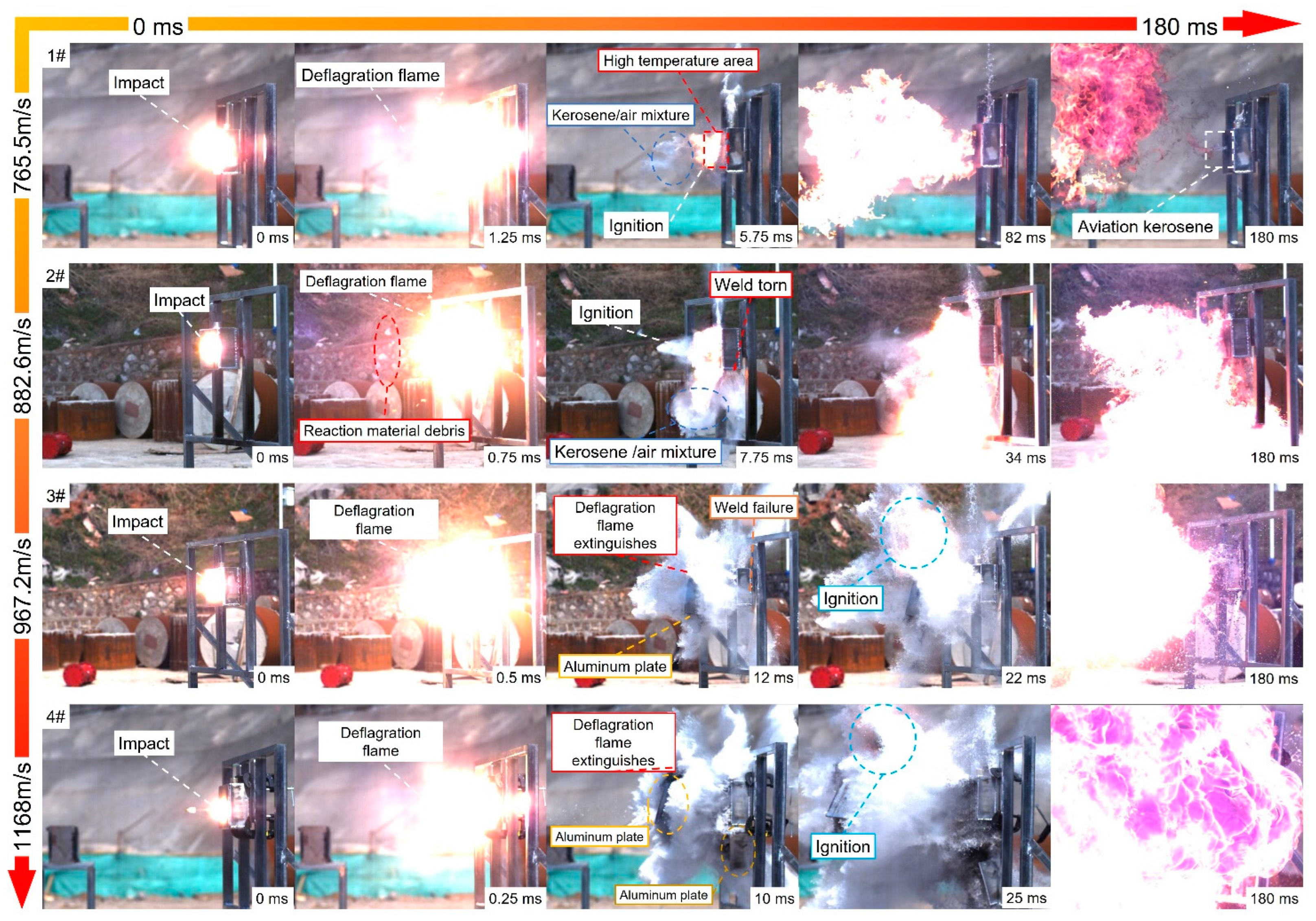
Figure 3 shows the ignition phenomena of the PABs (PTFE/Al/Bi2O3 reactive material) impacting the fuel tanks at different velocities during 0 to 180 ms. When the impact velocity was 765.5 m/s (1#), the reactive projectile broke instantaneously, forming a large number of reactive fragments that impacted the front aluminum plate of the fuel tank. The deflagration flame generated by the energy release reaction expanded rapidly outside the fuel tank in the form of a “bright ball” and reached the maximum firelight at 1.25 ms. At 5.75 ms, the aviation kerosene sprayed from the perforation was fully mixed with air to form a kerosene/air mixture, which was directly ignited. The flame spread from near the area of the perforation to the whole kerosene/air mixture and the kerosene/air mixture completely burned in 82 ms. At 180 ms, the pressure in the fuel tank dropped to the same as the external atmospheric pressure, and the remaining kerosene leaked outward from the perforation. The flame extinguished at 382 ms, and most of the aviation kerosene remained in the tank.
When the impact velocity was 882.6 m/s (2#), the deflagration flame produced by the energy release reaction reached the maximum firelight at 0.75 ms. At 4 ms, the welds at the bottom of the fuel tank cracked. The aviation kerosene that had been atomized, evaporated, and pyrolyzed under the action of a strong impact and high heat was ejected from the cracked welds at the bottom of the fuel tank and formed a large area of kerosene/air mixture with the surrounding air. At 7.75 ms, the kerosene/air mixture was first ignited on the front of the fuel tank, and it all ignited in less than 30 ms to form a large-area flame. As the kerosene continued to leak from the cracks, the continuous combustion of the kerosene/gas mixture was more intense. The high-temperature flame gradually wrapped the fuel tank. The combustion duration exceeded 500 ms, and all the kerosene in the tank was ignited.
When the impact velocity was 967.2 m/s (3#), due to the increase of velocity, the HRAM effect was further enhanced, resulting in the tearing of all the welds on the front of the fuel tank at 3.75 ms, and the front aluminum plate was separated from the fuel tank along the opposite direction of the impact due to high pressure. At the same time, all kerosene in the tank sprayed outward at a high velocity, which intensified the atomization degree and mixed more fully with the air. However, the deflagration flame caused by the PAB disappeared at 12 ms, but the kerosene/gas mixture was gradually ignited from the central area at 22 ms and developed into continuous combustion and was completely ignited at 123 ms. When the impact velocity was increased to 1168 m/S (4#), the overall phenomenon is similar to 3# in that the welds of the fuel tank were cracked after being impacted. The difference is that the structure of the fuel tank was more seriously damaged (the front and bottom aluminum plates separated from the tank at the same time). Similarly, the deflagration flame extinguished at 10 ms, the kerosene/air mixture was ignited at 25 ms, and all were completely ignited at 98 ms to form a bright flame.

3.2. The APs and SP Impact the Full Fuel Tank

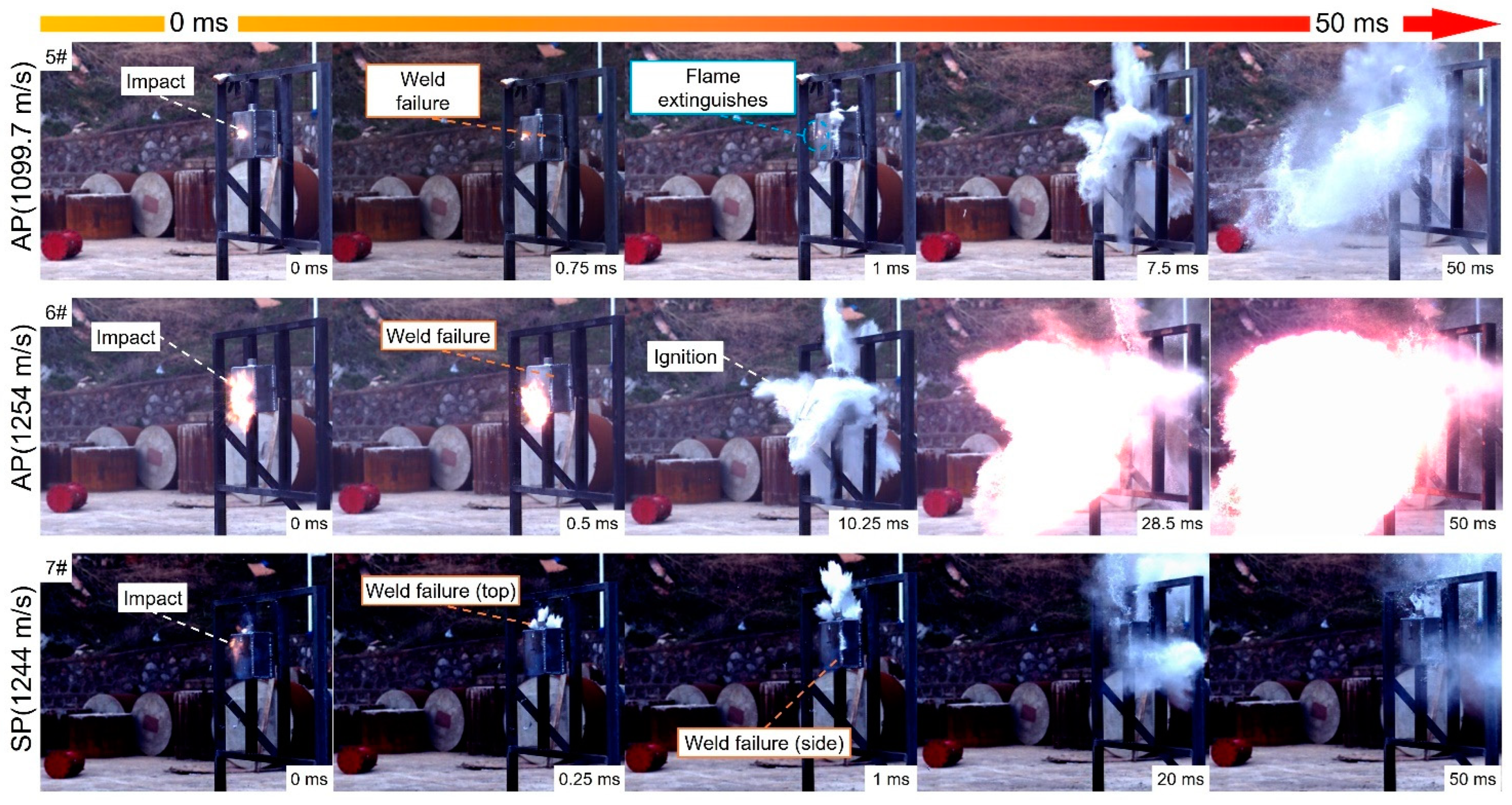
The phenomena of aluminum projectiles (APs) and the steel projectile (SP) impacting the fuel tanks are shown in Figure 4. When the AP impacted the fuel tank at a velocity of 1099.7 m/s (5#), the AP collided with the front aluminum plate on the fuel tank to engender a weak flame, which quickly vanished in less than 1 ms. At 0.75 ms, the fuel tank welds were cracked, and the fuel tank structure was damaged. Then, a large amount of atomized kerosene sprayed around, but the ignition failed. When the velocity increased to 1254 m/s (6#), the flame range induced by the AP became larger, and the weld was cracked in a shorter time (0.5 ms). Then, the structure of the fuel tank was completely damaged, and the kerosene/air mixture was ignited in the front of the fuel tank at 10.25 ms. The SP impacted the fuel tank at a velocity of 1244 m/s (7#) to produce a weak firelight, which disappeared in less than 0.25 ms. Since the impact position was close to the upper part of the fuel tank, the weld on the top of the fuel tank was damaged first, followed by the cracks on the side weld, and the kerosene ejected outward without being ignited.

3.3. The PABs Impact the Fuel Tank Filled with 50% Kerosene

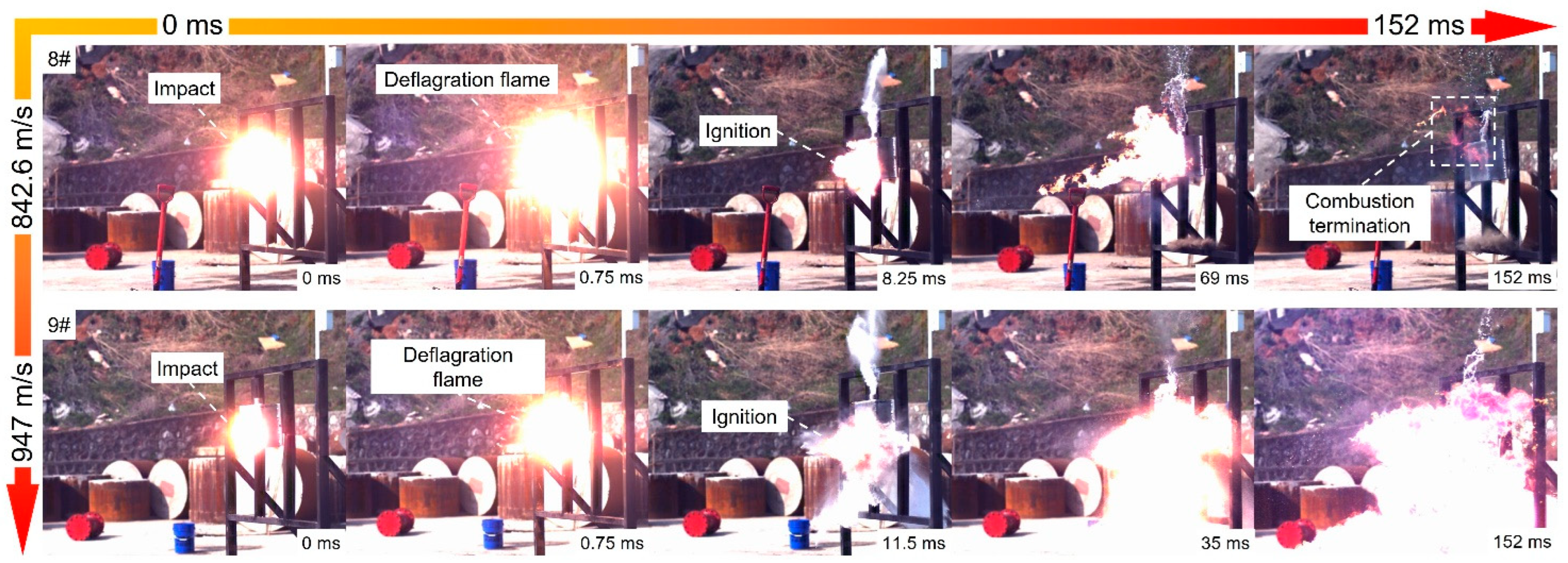
The ignition phenomena of the PABs impacting the fuel tank filled with 50% kerosene are shown in Figure 5. When the PAB struck the kerosene layer of the fuel tank filled with 50% kerosene with a velocity of 842.6 m/s (8#), the deflagration flame reached the maximum firelight at 0.75 ms, and a high kerosene column sprayed from the upper round hole. The fuel tank structure remained intact, and the kerosene atomized by impact and heated by a high temperature only sprayed outward from the perforation, so the kerosene was ignited in the front of the tank. At 69 ms, all the kerosene ejected from the perforation was ignited, and the whole combustion process lasted for 83 ms. When the velocity increased to 947 m/s (9#), the weld cracked in 4.5 ms, the atomized kerosene sprayed from the weld cracks at the bottom of the tank, and the kerosene/gas mixture was ignited in the front of the tank. At 35 ms, all the ejected kerosene was ignited, and the combustion process lasted for more than 500 ms.

4. Discussion

4.1. Influence of Energy Release Reaction to Ignition Effect of the Projectile Impacting the Fuel Tank

Active metals such as Al have a strong oxidation reaction with oxygen under impact conditions, releasing a lot of heat and producing a high temperature. However, due to the low velocity (1099.7 m/s), even if the impact made the fuel tank rupture, the heat released by the AP did not reach the combustion threshold of the kerosene/gas mixture, so the test 5# failed to ignite the kerosene. When the velocity increased (1254 m/s), the oxidation reaction of Al was more intense and released more heat. At the same time, the hot aluminum fragments and aluminum ions transferred heat to the kerosene/air mixture through heat conduction, so that the kerosene/air mixture successfully reached the ignition conditions. The SP, as an inert metal projectile, only ignited kerosene by kinetic energy, instantaneous high-speed shear deformation of the fuel tank shell, and heat generated by the high-speed strain of the steel projectile. This heat is easily lost, so it is very difficult for SP to ignite kerosene after impact, and kerosene cannot be ignited even at a high velocity of 1244 m/s.
By comparing the results of PAB, AP, and SP impacting the fuel tank, it can be found that PAB ignited part of kerosene at the velocity of 765.5 m/s and completely ignited kerosene at the velocity of 882.6 m/s, while AP could not ignite kerosene even at the velocity of 1099.7 m/s. AP ignited kerosene at 1254 m/s, but SP could not ignite kerosene even if its velocity reached 1244 m/s. This indicates that although the impact kinetic energy and initial shockwave pressure of the PAB and AP were lower than those of the SP, the energy release reaction after impact enhanced the HRAM effect and the cavity expansion effect, and helped to provide additional ignition heat sources for the kerosene/air mixture, so that PAB and AP had stronger ignition performance than SP. In addition, the ignition ability of the PAB was stronger than that of the AP, which was due to the following reactions of PAB under high-speed impact [22]:
2Al+ Bi2O3 → 2Bi+Al2O3
4Al+3(-C2F4-) → 4AlF3+6C
4Bi+3(-C2F4-) → 4BiF3+6C
On the one hand, this complex reaction mechanism can release more heat than the single reaction between aluminum and oxygen. On the other hand, due to the low boiling point of Bi, the generation of Bi gas under a high reaction heat can not only improve the reaction activity but can also enhance the HRAM effect and the cavity expansion effect. Through the above analysis, it can be concluded that the order of ignition ability is PAB, AP, and SP, from strong to weak.

4.2. Influence of Kerosene Content on the Ignition Effect of PAB Impacting the Fuel Tank

Through the comparative test 8# and test 1#, test 9#, and test 2#, it can be noticed that the experimental phenomenon of PAB impacting the fuel tank filled with 50% kerosene at a higher velocity was similar to that of PAB impacting the full fuel tank at a lower velocity. The damage behaviors of the fuel tanks containing 50% kerosene after being impacted are shown in Figure 6. Comparing Figure 6 and Figure 7, it can be seen that the damage results of test 8# and test 1# on the fuel tank were similar, which shows that the welds of the fuel tank were complete (Figure 6b and Figure 7b). Both the test 9# and test 2# can break the welds of the fuel tank but cannot damage the overall structure of the fuel tank (Figure 6d and Figure 7d). This phenomenon can be explained as follows: On the one hand, the compression shockwave induced by PAB hitting the front aluminum plate of the full fuel tank was transmitted to kerosene, which can further act on the aluminum plate on each side and meet and stack at the weld, which makes it easy to form stress concentration, resulting in weld fracture and even fuel tank damage. When impacting the kerosene layer of the fuel tank filled with 50% kerosene, due to the existence of the kerosene–air interface in the tank, the compression shockwave was reflected when it propagated to the free surface, resulting in reverse unloading waves, leading to the weakening of the impact on the tank wall. On the other hand, the energy release reaction of the reactive material in the liquid environment strengthened the cavity expansion effect. When PAB fragments reacted in the kerosene layer of the fuel tank filled with 50% kerosene, due to much air existing in the tank, the load acting on the tank greatly decreased during kerosene expansion, resulting in less deformation of the tank. Therefore, the damage degree and ignition effect of PAB impacting the fuel tank filled with 50% kerosene were weaker than those of impacting the full fuel tank. If the same effect needs to be achieved, the speed of impacting the fuel tank filled with 50% kerosene needs to be increased (about 60~70 m/s).

4.3. Influence of Velocity on Ignition Effect of PAB Impacting the Fuel Tank

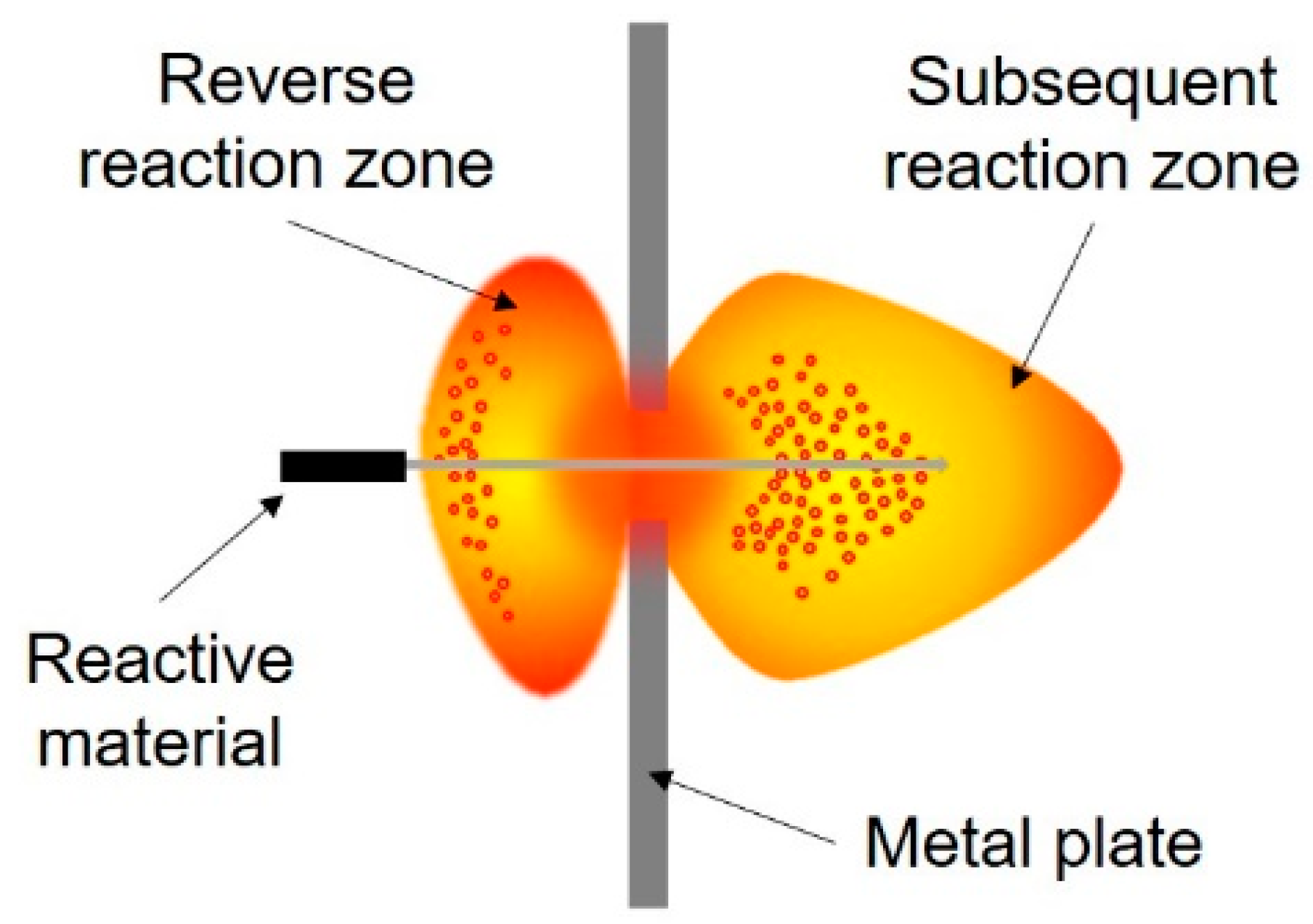
As shown in Figure 8, when the reactive material impacted the target plate, it broke instantly and formed a large number of fragments. Some fragments released energy along the opposite direction of impact to form a reverse reaction zone on the front of the target plate, and the other fragments released energy along the impact direction to form a subsequent reaction zone behind the target plate [24]. In fact, the bright deflagration flame formed on the front of the fuel tank when PAB impacted was generated by the rapid energy release of activated fragments in the reverse reaction zone.
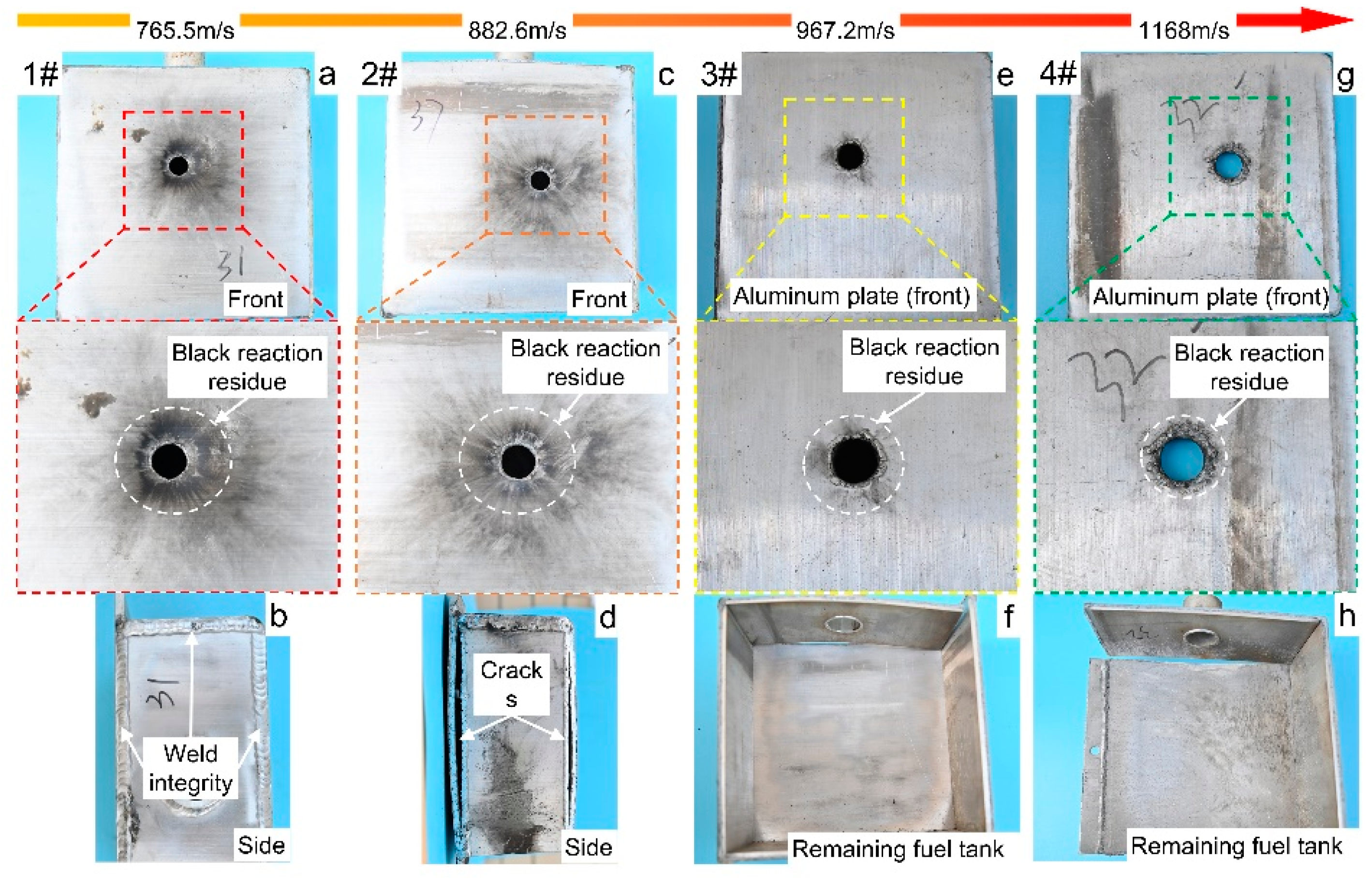
Through the comparative tests 1#–4#, it was discovered that the increase of velocity intensified the damage of PAB to the fuel tank structure. Figure 7 shows the damage behaviors of the fuel tanks after PAB impacted the full fuel tank at different velocities. At the beginning, the impact velocity of the PAB was low (1#), which was not enough to break the weld of the fuel tank (Figure 7b). With the increase of impact velocity (2#), PAB could split the weld (Figure 7d). When the velocity was further increased (3# and 4#), the structure of the fuel tank was completely ruptured (Figure 7f,h). This can be explained as follows: on the one hand, the increase of velocity caused PAB to release greater kinetic energy in the fuel tank, and on the other hand, the subsequent reaction zone released more energy with the increasing velocity [24]. Therefore, under the dual-promotion of kinetic and chemical energy, the fuel tank structure will suffer more serious damage.
Figure 7 also shows the details around the perforation of the front aluminum plate of the fuel tank after the impact of PAB at different velocities. As shown in the figure, there were more black reaction residues around the perforation at lower velocities (1# and 2#) than at high velocities (3# and 4#), which displays that the active fragments involved in the energy release reaction in the reverse reaction zone were reduced at high velocity. In addition, it can be seen from Figure 3 that the flame of the reverse reaction zone in the test 3# disappeared at 12 ms, while the flame of the reverse reaction zone in the test 4# went out at 10 ms, indicating that the increase of velocity led to the reduction of the duration of the flame in the reverse reaction zone.
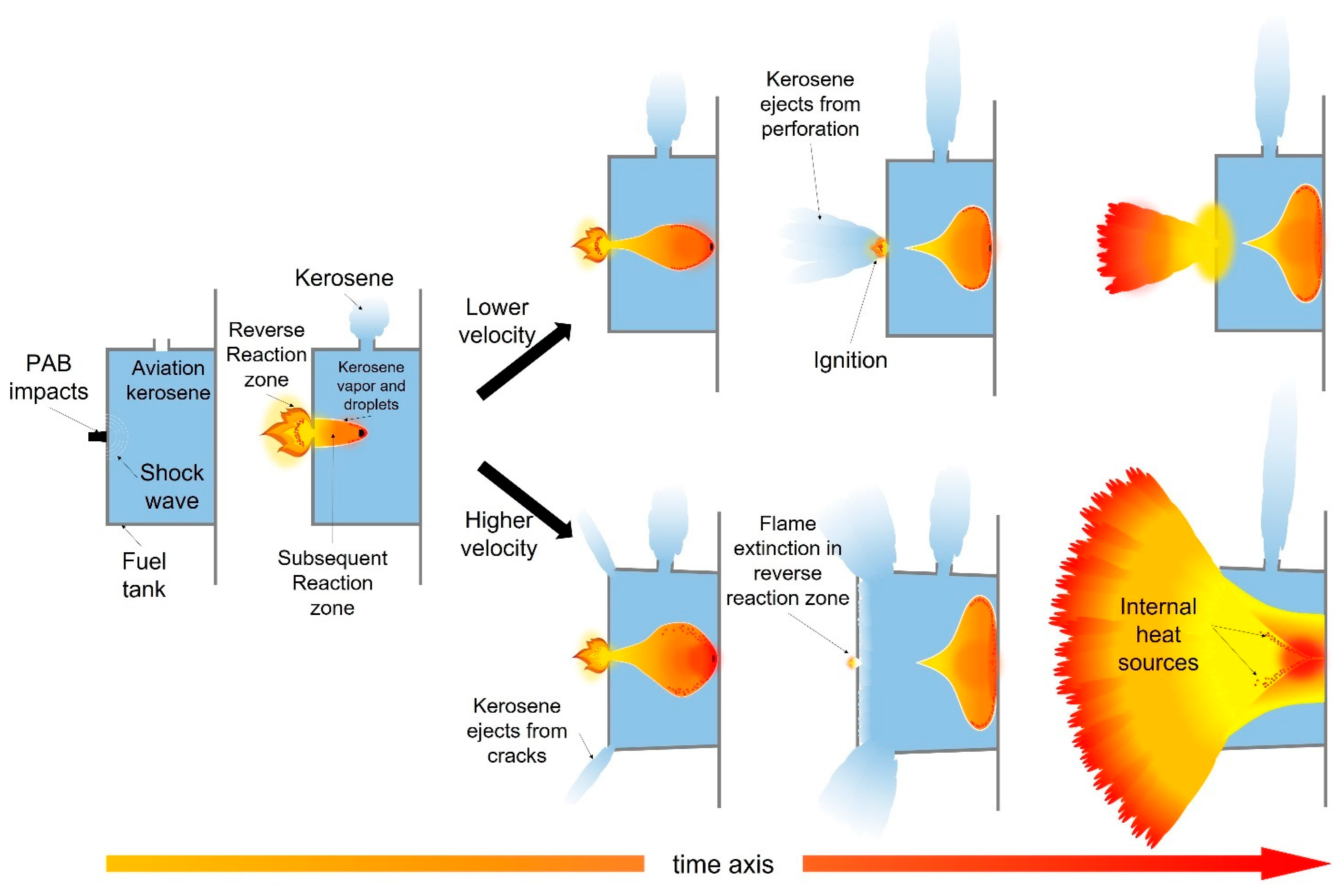
Through the above analysis and combined with high-speed photos, the schematic diagram of the ignition process of the PABs’ impact on fuel tanks was drawn, as shown in Figure 9. At a low-impact velocity, because the weld could not be split and the tank structure remained intact, aviation kerosene only ejected out of the tank from the incident hole and the upper round hole or leaked from the cracked weld under the action of high pressure. The atomized kerosene ejecting out of the incident hole only passed through the continuous flame produced by the energy release of activated fragments in the reverse reaction zone. Once the atomized kerosene was mixed with air to reach the ignition concentration, the kerosene/air mixture was ignited on the front of the tank. Although the activated fragments penetrating the front aluminum plate of the fuel tank into the subsequent reaction zone can provide heat sources for kerosene in the flight channel, due to the lack of oxygen in the channel, even if the energy in the subsequent reaction zone is higher than that in the reverse reaction zone [20], kerosene cannot be ignited. When the velocity was high, the kinetic energy and reactive chemical energy were both increased, which significantly enhanced the HRAM effect and the cavity expansion effect. The weld was directly broken under high pressure, and a large amount of kerosene sprayed outward along the cracked weld. However, due to the increase of velocity, the decrease of active fragments in the reverse reaction zone led to the reduction of the flame duration in this zone. In addition, the front aluminum plate moved at a high velocity in the opposite direction of impact under high pressure. The existence of the aluminum plate delayed the movement of kerosene after the reverse reaction zone, resulting in the atomized kerosene not being able to contact the flame until the flame in the reverse reaction zone extinguished. Therefore, the kerosene was not ignited by the flame in the reverse reaction zone. After that, with the complete destruction of the fuel tank, all kerosene sprayed outward at a high velocity, and a large amount of air was mixed into the kerosene to provide aerobic conditions. Finally, kerosene was ignited by highly thermally activated fragments in the subsequent reaction zone.
To sum up, it can be concluded that PABs have different damage behaviors and ignition modes for the fuel tank structure and kerosene under different impact velocities. The increase of impact velocity directly resulted in the growth of impact kinetic energy and reaction chemical energy, and then led to the enhancement of the HRAM effect in the fuel tank. The damage mode on the fuel tank changed from structural integrity to weld fracture until the final fuel tank was ruptured. The change of the energy release characteristics of reactive materials and the damage behavior of the fuel tank promoted the conversion of the aviation kerosene ignition mode: when the velocity was low, aviation kerosene was ignited by the continuous flame in the reverse reaction zone, while when the speed was high, the high-temperature-activated reactive fragments were the ignition heat source.

5. Conclusions

In this paper, a series of impact fuel tank experiments were carried out by means of ballistic gun firing. The differences in ignition ability between PTFE/Al/Bi2O3 and metal aluminum and metal steel were compared and analyzed. The damage mode of the fuel tank and the ignition mechanism of kerosene when the PTFE/Al/Bi2O3 reactive material impacted at different velocities were explored.
  • Under different impact velocities, PAB reactive materials have different damage behaviors and ignition modes for the fuel tank and kerosene, respectively. With the increase of the impact velocity, the fuel tank changed from structural integrity to weld fracture, until it was finally damaged. The change of the energy release characteristics of reactive materials and the damage behavior of the fuel tank promoted the conversion of aviation kerosene ignition mode: aviation kerosene was ignited by the flame in the reverse reaction zone at a low velocity, while the high-temperature-activated reaction fragments were the ignition heat source at a high speed.
  • PAB completely ignited kerosene at the velocity of 882.6 m/s. AP ignited kerosene at the velocity of 1254 m/s, but not at the velocity of 1099.7 m/s. SP could not ignite kerosene even if it reached the velocity of 1244 m/s. The order of ignition ability of these three materials is: PAB > AP > SP.
  • The damage degree and ignition effect of PAB impacting the fuel tank filled with 50% kerosene were weaker than those of impacting the full fuel tank. If the same effect needs to be achieved, the speed of impacting the fuel tank filled with 50% kerosene needs to be increased (about 60–70 m/s).

Author Contributions

Y.L. and J.W. conceived and designed the experiments; M.Y., R.W., Z.G., R.L. and J.H. performed the experiments; Q.Y., S.W. and Y.L. analyzed the data; R.W. wrote the paper. All authors have read and agreed to the published version of the manuscript.

Funding

This research was funded by the National Natural Science Foundation of China (No. 51673213).

Data Availability Statement

Not applicable.

Acknowledgments

The financial support from the National Natural Science Foundation of China (General Program, Grant No. 51673213) is gratefully acknowledged.

Conflicts of Interest

The authors declare no conflict of interest.

References

  1. Cai, H.L.; Song, B.F.; Pei, Y.; Shi, S. Fuel Leaking Analysis of Fuel Tank by Projectiles Impact with Mechanical Properties of Projectiles. Adv. Mater. Res. 2012, 644, 203–206. [Google Scholar] [CrossRef]
  2. Varas, D.; Zaera, R.; Lopez-Puente, J. Numerical modelling of partially filled aircraft fuel tanks submitted to Hydrodynamic Ram. Aerosp. Sci. Technol. 2012, 16, 19–28. [Google Scholar] [CrossRef] [Green Version]
  3. Bing, C. Experimental Study on the Impact Inflame Damage to Simulative Fuel Tank of Cruise Missile by Fragments. Chin. J. Explos. Propellants 2008, 31, 45–49. [Google Scholar]
  4. Wang, H.F.; Zheng, Y.F.; Yu, Q.B.; Liu, Z.W.; Yu, W.M. Impact-induced initiation and energy release behavior of reactive materials. J. Appl. Phys. 2011, 110, 074904. [Google Scholar] [CrossRef]
  5. Xu, F.Y.; Zheng, Y.F.; Yu, Q.B.; Zhang, X.P.; Wang, H.F. Damage effects of aluminum plate by reactive material projectile impact. Int. J. Impact Eng. 2017, 104, 38–44. [Google Scholar] [CrossRef]
  6. Xu, F.Y.; Zheng, Y.F.; Yu, Q.B.; Wang, Y.Z.; Wang, H.F. Experimental study on penetration behavior of reactive material projectile impacting aluminum plate. Int. J. Impact Eng. 2016, 95, 125–132. [Google Scholar] [CrossRef]
  7. Wang, H.F.; Geng, B.Q.; Guo, H.G.; Zheng, Y.F.; Yu, Q.B.; Ge, C. The effect of sintering and cooling process on geometry distortion and mechanical properties transition of PTFE/Al reactive materials. Def. Technol. 2020, 16, 720–730. [Google Scholar] [CrossRef]
  8. Feng, B.; Fang, X.; Wang, H.X.; Dong, W.; Li, Y.C. The Effect of Crystallinity on Compressive Properties of Al-PTFE. Polymers 2016, 8, 356. [Google Scholar] [CrossRef] [Green Version]
  9. Liu, S.B.; Yuan, Y.; Zheng, Y.F.; Ge, C.; Wang, H.F. Enhanced ignition behavior of reactive material projectiles impacting fuel-filled tank. Def. Technol. 2019, 15, 533–540. [Google Scholar] [CrossRef]
  10. Wang, H.; Xie, J.; Ge, C.; Guo, H.; Zheng, Y. Experimental investigation on enhanced damage to fuel tanks by reactive projectiles impact. Def. Technol. 2021, 17, 599–608. [Google Scholar] [CrossRef]
  11. Wang, L.; Liu, J.X.; Li, S.K.; Zhang, X.B. Investigation on reaction energy, mechanical behavior and impact insensitivity of W-PTFE-Al composites with different W percentage. Mater. Des. 2016, 92, 397–404. [Google Scholar] [CrossRef]
  12. Zhou, L.; Piekiel, N.; Chowdhury, S.; Zachariah, M.R. Time-Resolved Mass Spectrometry of the Exothermic Reaction between Nanoaluminum and Metal Oxides: The Role of Oxygen Release. J. Phys. Chem. C. 2010, 114, 14269–14275. [Google Scholar] [CrossRef]
  13. Wu, J.X.; Feng, B.; Gao, Z.R.; Li, Y.C.; Wu, S.Z.; Yin, Q.; Huang, J.Y.; Ren, X.X. Investigation on the thermal decomposition and thermal reaction process of PTFE/Al/MoO3 fluorine-containing thermite. J. Fluorine Chem. 2021, 241, 109676. [Google Scholar] [CrossRef]
  14. Zhang, J.; Huang, J.; Fang, X.; Li, Y.; Yu, Z.; Gao, Z.; Wu, S.; Yang, L.; Wu, J.; Kui, J. Thermal Decomposition and Thermal Reaction Process of PTFE/Al/MnO2 Fluorinated Thermite. Materials 2018, 11, 2451. [Google Scholar] [CrossRef] [Green Version]
  15. Huang, J.Y.; Fang, X.; Li, Y.C.; Feng, B.; Wang, H.X.; Du, K. The Mechanical and Reaction Behavior of PTFE/Al/Fe2O3 under Impact and Quasi-Static Compression. Adv. Mater. Sci. Eng. 2017, 2017, 3540320. [Google Scholar] [CrossRef] [Green Version]
  16. Wu, J.X.; Feng, B.; Gao, Z.R.; Yin, Q.; Huang, J.Y.; Wu, S.Z.; Li, Y.C. Effect of multi-oxidants on mechanical response and reactive characteristics of PTFE/Al reactive material under dynamic impact. Mater. Lett. 2021, 283, 128886. [Google Scholar] [CrossRef]
  17. Glavier, L.; Taton, G.; Ducere, J.M.; Baijot, V.; Pinon, S.; Calais, T.; Esteve, A.; Rouhani, M.D.; Rossi, C. Nanoenergetics as pressure generator for nontoxic impact primers: Comparison of Al/Bi2O3, Al/CuO, Al/MoO3 nanothermites and Al/PTFE. Combust. Flame. 2015, 162, 1813–1820. [Google Scholar] [CrossRef]
  18. Martirosyan, K.S.; Wang, L.; Vicent, A.; Luss, D. Synthesis and performance of bismuth trioxide nanoparticles for high energy gas generator use. Nanotechnology 2009, 20, 405609. [Google Scholar] [CrossRef]
  19. Martirosyan, K.S.; Wang, L.; Luss, D. Tuning the Gas Pressure Discharge of Nanoenergetic Materials by Boron and Carbon Nanotubes Additives. In Proceedings of the NSTI Nanotechnology Conference and Expo, Boston, MA, USA, 13–16 June 2011; pp. 323–326. [Google Scholar]
  20. Yuan, Y.; Geng, B.Q.; Sun, T.; Yu, Q.B.; Wang, H.F. Impact-Induced Reaction Characteristic and the Enhanced Sensitivity of PTFE/Al/Bi2O3 Composites. Polymers 2019, 11, 2049. [Google Scholar] [CrossRef] [Green Version]
  21. Yuan, Y.; Liu, Z.Y.; He, S.; Ge, C.; Yu, Q.B.; Zheng, Y.F.; Wang, H.F. Shock-induced reaction behaviors of functionally graded reactive material. Def. Technol. 2021, 17, 1687–1698. [Google Scholar] [CrossRef]
  22. Lan, J.; Liu, J.X.; Zhang, S.; Xue, X.Y.; He, C.; Wu, Z.Y.; Yang, M.; Li, S.K. Influence of multi-oxidants on reaction characteristics of PTFE-Al-XmOY reactive material. Mater. Des. 2020, 186, 108325. [Google Scholar] [CrossRef]
  23. Zhang, J.; Li, Y.C.; Huang, J.Y.; Wu, J.X.; Liu, Q.; Wu, S.Z.; Gao, Z.R.; Zhang, S.; Yang, L. The effect of al particle size on thermal decomposition, mechanical strength and sensitivity of Al/ZrH2/PTFE composite. Def. Technol. 2021, 17, 829–835. [Google Scholar] [CrossRef]
  24. Feng, S.S.; Wang, C.L.; Huang, G.Y. Experimental Study on the Reaction Zone Distribution of Impact-Induced Reactive Materials. Propellants Explos. Pyrotech. 2017, 42, 896–905. [Google Scholar] [CrossRef]
Figure 1. (a) PTFE/Al/Bi2O3 reactive projectile, (b) the bullet sample, and (c) the steel projectile and the Al projectile.
Metals 13 00399 g001
Figure 2. (a) The layout of the experimental test system. (b) The 12.7 mm caliber ballistic gun. (c) The six-channel velocimeter. (d) The FASTCAMSA-Z high-speed camera. (e) The fuel tank.
Metals 13 00399 g002
Figure 3. The ignition phenomena of the PABs impacting the fuel tanks at different velocities: (1#) 765.5 m/s, (2#) 882.6 m/s, (3#) 967.2 m/s, and (4#) 1168.0 m/s.
Metals 13 00399 g003
Figure 4. The phenomena of APs and the SP impacting the fuel tank at different velocities: (5#) AP with 1099.7 m/s, (6#) AP with 1254 m/s, and (7#) SP with 1244 m/s.
Metals 13 00399 g004
Figure 5. The ignition phenomena of the PABs impacting the fuel tank filled with 50% kerosene at different velocities: (8#) 842.6 m/s and (9#) 947 m/s.
Metals 13 00399 g005
Figure 6. The damage behaviors of the fuel tanks filled with 50% kerosene when PABs impact at different velocities: (a) front of 8# fuel tank, (b) side of 8# fuel tank, (c) front of 9# fuel tank, and (d) side of 9# fuel tank.
Metals 13 00399 g006
Figure 7. The damage behaviors of the fuel tanks when PABs impact at different velocities: (a) front of 1# fuel tank, (b) side of 1# fuel tank, (c) front of 2# fuel tank, (d) side of 2# fuel tank, (e) front aluminum plate of 3# fuel tank, (f) remaining part of 3# fuel tank, (g) front aluminum plate of 4# fuel tank, and (h) remaining part of 2# fuel tank.
Metals 13 00399 g007
Figure 8. The schematic diagram of the energy release reaction of active material impacting the metal plate.
Metals 13 00399 g008
Figure 9. The schematic diagram of the ignition process of the PABs’ impact on fuel tanks.
Metals 13 00399 g009
Table 1. The scheme and results of the impact experiments.
Test NumberProjectile TypeTargetImpact Velocity (m/s)Ignition Time (ms)Damage Degree of Fuel TankIgnition Status
1#PABImpletion765.55.75IntactnessPart
2#PABImpletion882.67.75Weld crackingWhole
3#PABImpletion967.222Tank rupturedWhole
4#PABImpletion1168.025Tank rupturedWhole
5#APImpletion1099.7-Tank ruptured-
6#APImpletion1254.010.25Tank rupturedWhole
7#SPImpletion1244.0-Tank ruptured-
8#PABHalf842.68.25IntactnessPart
9#PABHalf947.011.5Weld crackingWhole
Disclaimer/Publisher’s Note: The statements, opinions and data contained in all publications are solely those of the individual author(s) and contributor(s) and not of MDPI and/or the editor(s). MDPI and/or the editor(s) disclaim responsibility for any injury to people or property resulting from any ideas, methods, instructions or products referred to in the content.