
Manufacturing Methods Induced Property Variations in Ti6Al4V Using High-Speed Machining and Additive Manufacturing (AM)


Abstract
1. Introduction
1.1. Analysis of Ti6Al4V in High-Speed Machining
1.2. Why Additive Manufacturing (AM) of Ti6Al4V Alloy
- Poor thermal conductivity leads to higher porosity in AM;
- Strain hardening proclivity;
- Susceptibility to react with oxygen actively.
- High heat input localization;
- Minimum time of interaction;
- High-temperature difference between layers;
- Superior cooling rates.
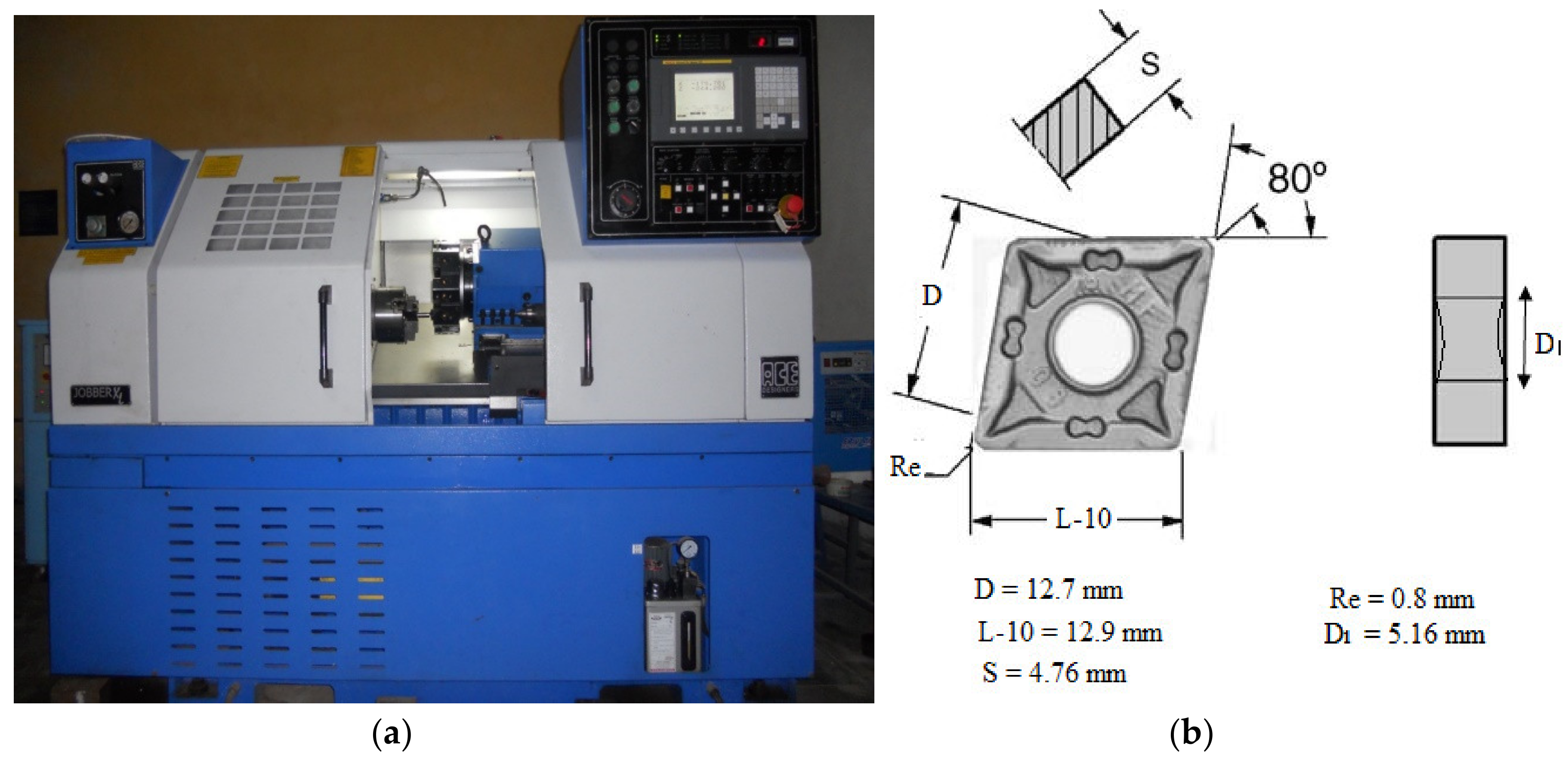
2. Materials and Methods
3. Results and Discussions
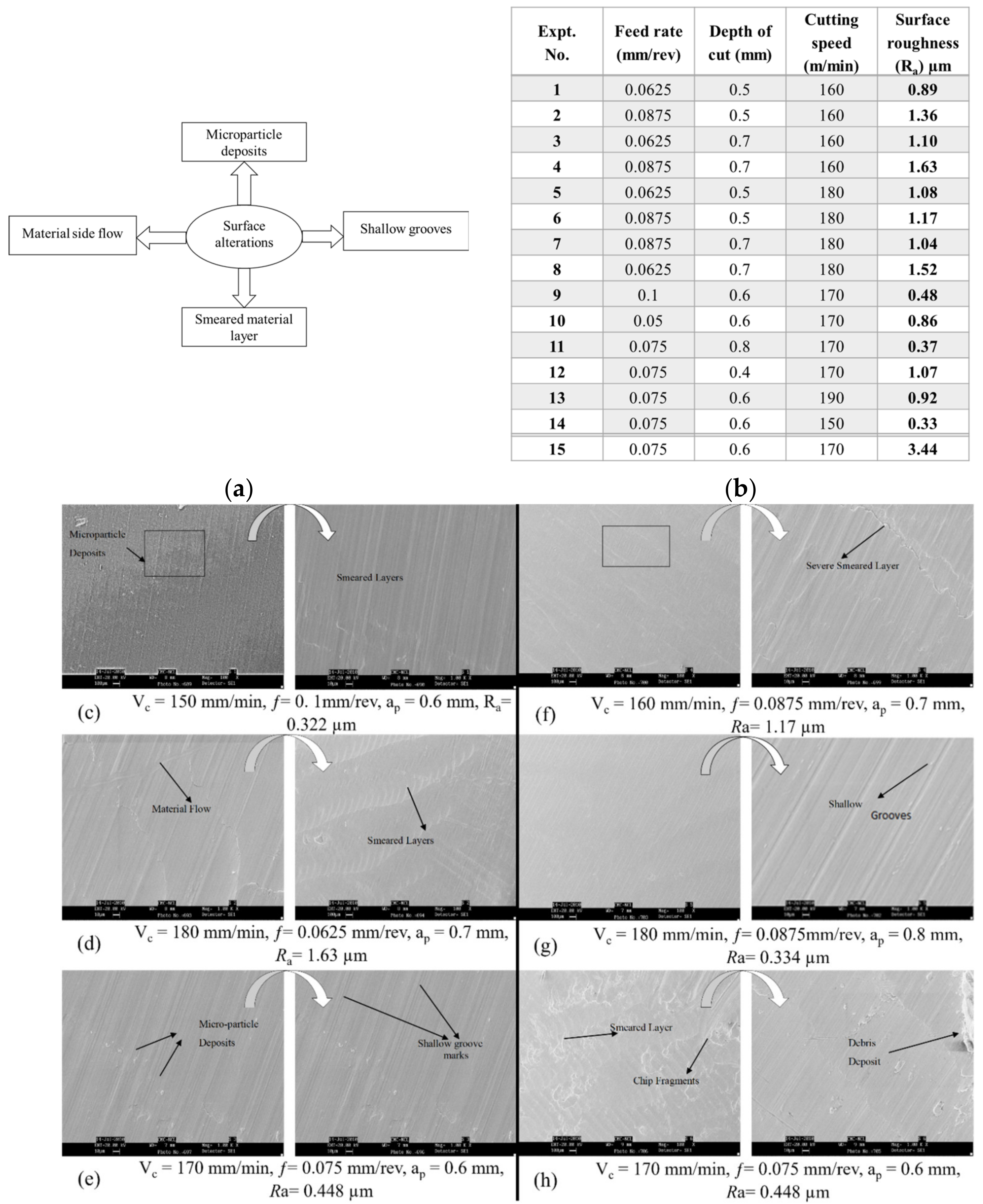
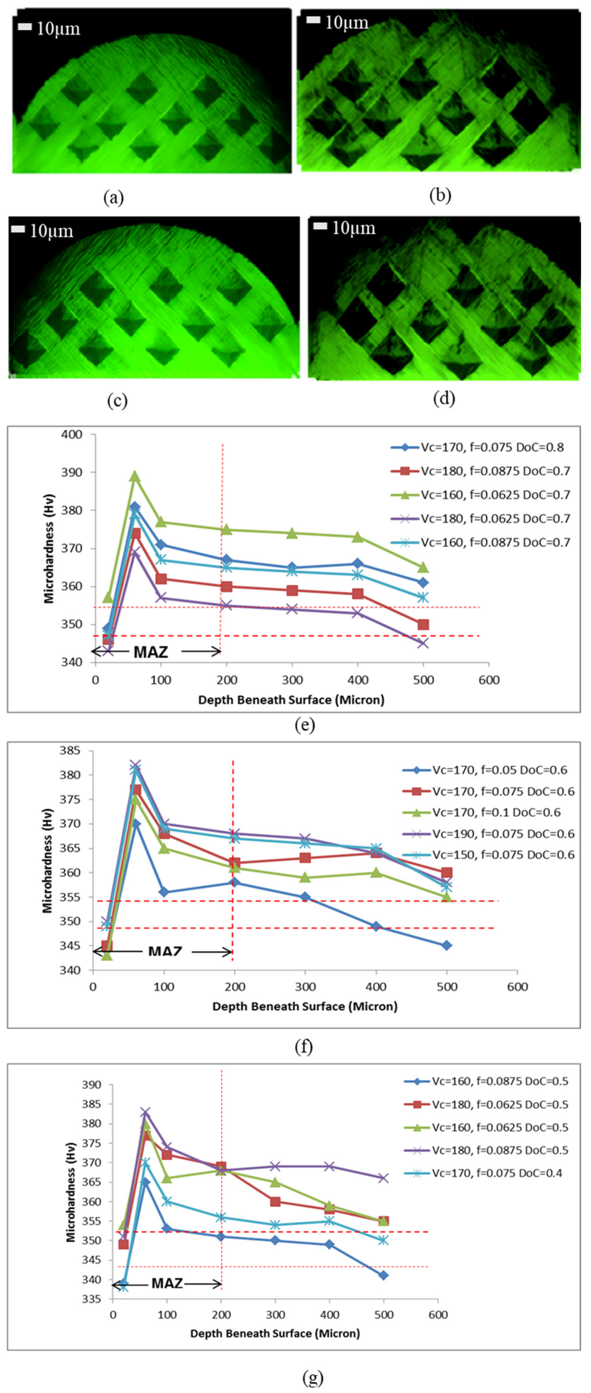
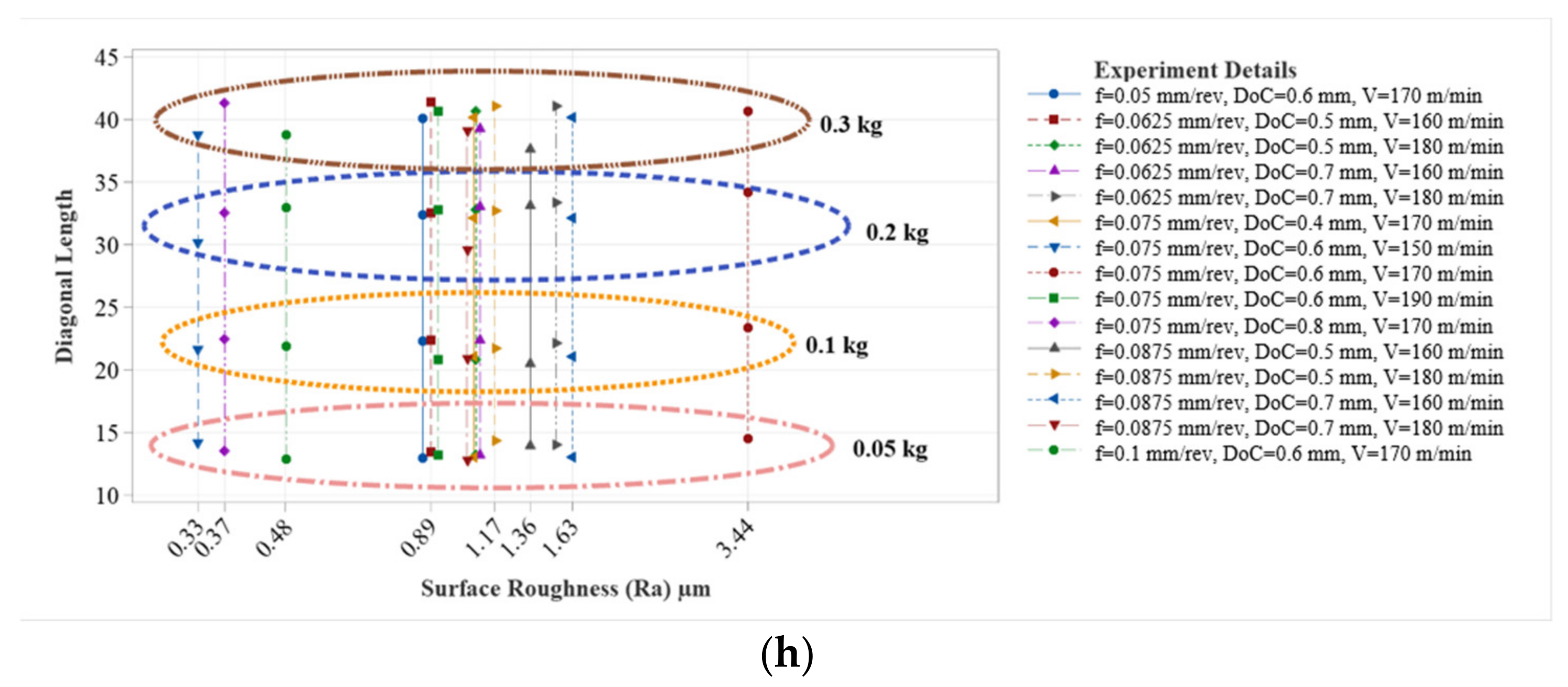
3.1. Discussion of Surface Alterations and Hardness in High-Speed Machining
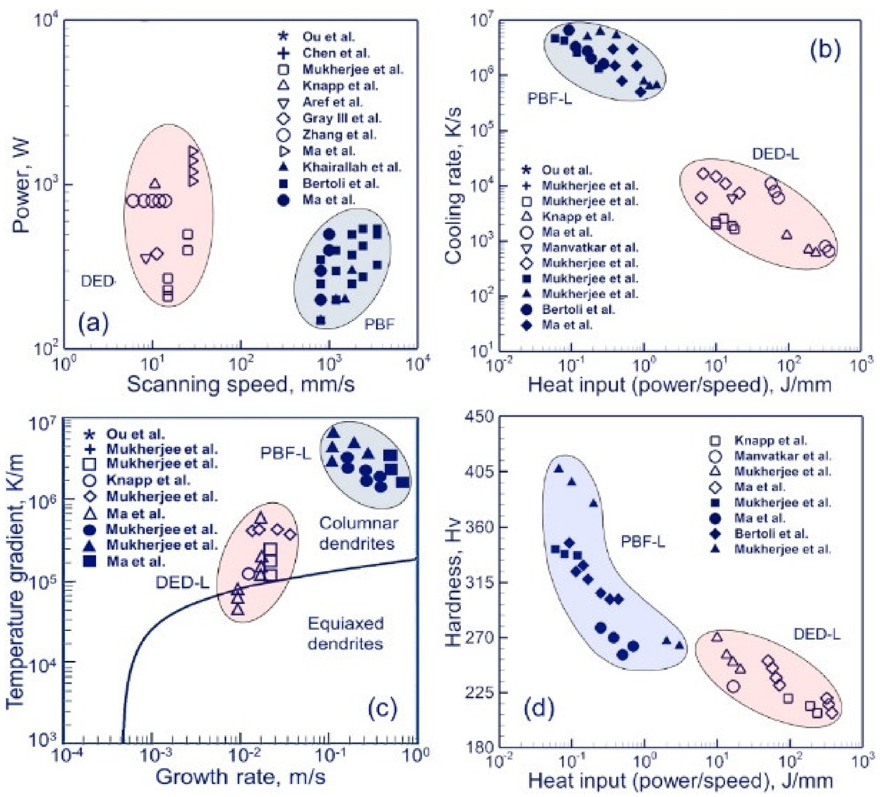
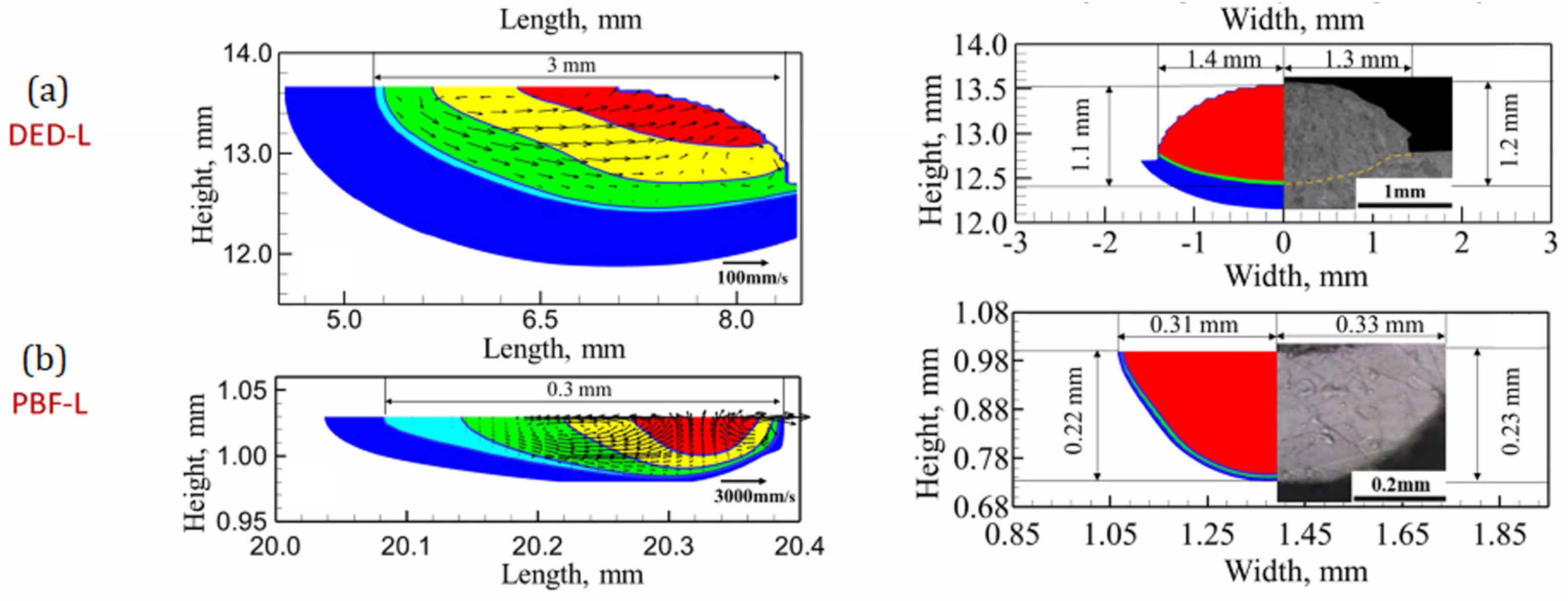
3.2. Discussion of the Effect of the Thermal Behavior on the Microstructure of AM of Ti6Al4V

| Thermal Properties | SLM | DED | EBM |
|---|---|---|---|
| Dominant heat dissipation | Conduction | Conduction and force convection | Conduction |
| Cooling rate (K/s) | 1.7 × 10⁴ [28] | 7 × 10⁴ [29] | 103 − 105 [30] |

3.2.1. Phase
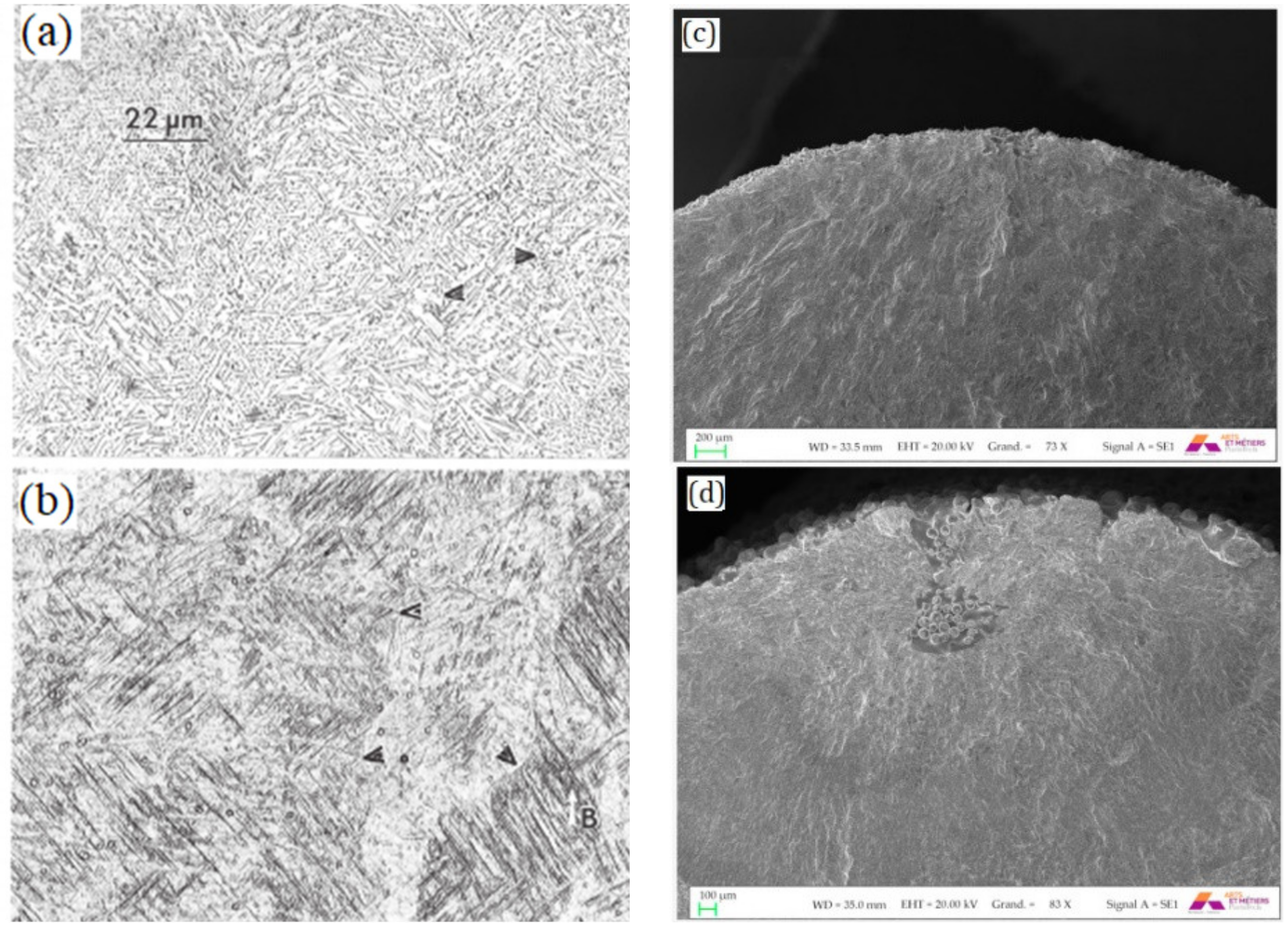
3.2.2. Grains
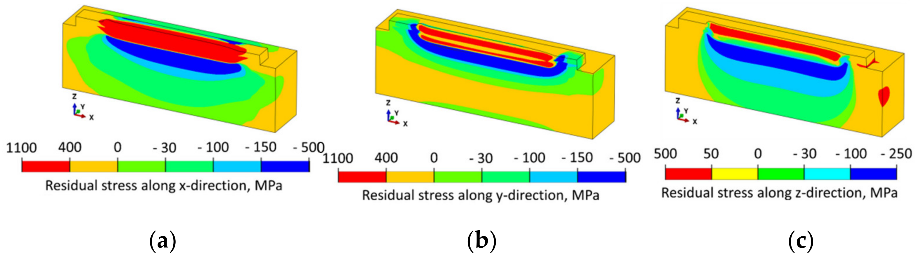
3.3. Defects and the Microstructure and Their Effects on Mechanical Properties and Residual Stress
3.3.1. Porosity
3.3.2. Surface Roughness
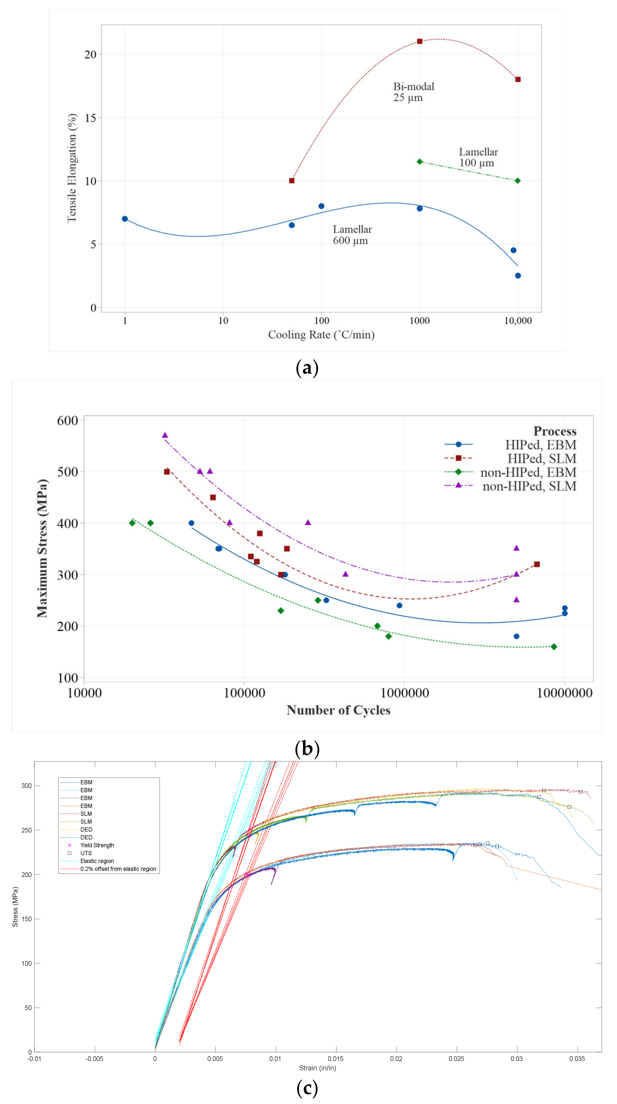
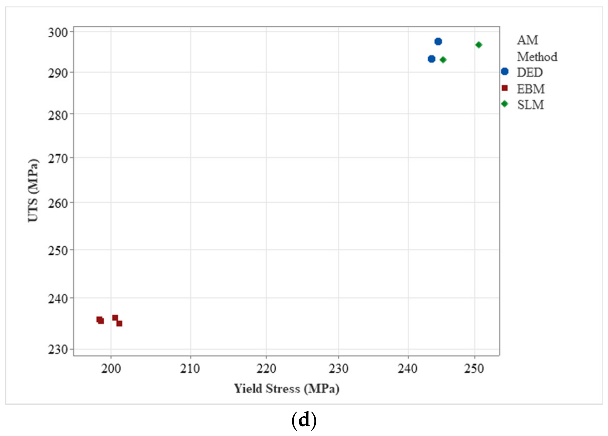
3.3.3. Tensile
3.3.4. Fatigue
4. Conclusions
Author Contributions
Funding
Data Availability Statement
Conflicts of Interest
References
- Pawade, R.; Khadtare, A.; Dhumal, D.; Wankhede, V. Machinability Assessment in High Speed Turning of High Strength Temperature Resistant Superalloys. J. Adv. Manuf. Syst. 2019, 18, 595–623. [Google Scholar] [CrossRef]
- Bhopale, N.N.; Pawade, R.S. Investigation of Surface Integrity in High-speed Ball End Milling of Cantilever Shaped Thin Plate of Inconel 718 Investigation of surface integrity in high-speed ball end milling of cantilever shaped thin plate of Inconel 718 Manufacturing and processing. J. Achiev. Mater. Manuf. Eng. 2012, 55, 616–622. Available online: https://www.researchgate.net/publication/283349251 (accessed on 12 December 2022).
- Kadam, G.; Pawade, R. Influence of Machining Environment on Surface Integrity in HSM of Inconel 718 with Productivity Perspective. Adv. Intell. Syst. Res. 2017, 137, 89–93. [Google Scholar] [CrossRef]
- Kadam, G.S.; Pawade, R.S. Surface integrity and sustainability assessment in high-speed machining of Inconel 718—An eco-friendly green approach. J. Clean. Prod. 2017, 147, 273–283. [Google Scholar] [CrossRef]
- Patil, N.; Asem, A.; Pawade, R.; Thakur, D.; Brahmankar, P. New Production technologies in aerospace industry—5th machining innovations conference (MIC 2014). Comparative Study of High Speed Machining of Inconel 718 in Dry Condition and by Using Compressed Cold Carbon Dioxide Gas as Coolant. Proc. CIRP 2014, 24, 86–91. [Google Scholar] [CrossRef][Green Version]
- Pawade, R.; Sonawane, H.A.; Joshi, S.S. An analytical model to predict specific shear energy in high-speed turning of Inconel. Int. J. Mach. Tools Manuf. 2009, 49, 979–990. [Google Scholar] [CrossRef]
- Pawade, R.; Joshi, S.S.; Brahmankar, P.; Rahman, M. An investigation of cutting forces and surface damage in high-speed turning of Inconel. J. Mater. Process. Technol. 2007, 192–193, 139–146. [Google Scholar] [CrossRef]
- Pawade, R.; Joshi, S.S.; Brahmankar, P. Effect of machining parameters and cutting edge geometry on surface integrity of high-speed turned Inconel. Int. J. Mach. Tools Manuf. 2008, 48, 15–28. [Google Scholar] [CrossRef]
- Pawade, R.S.; Joshi, S.S. Mechanism of chip formation in high-speed turning of inconel. Mach. Sci. Technol. 2011, 15, 132–152. [Google Scholar] [CrossRef]
- Jaffery, S.H.I.; Mativenga, P.T. Wear mechanisms analysis for turning Ti-6Al-4V—Towards the development of suitable tool coatings. Int. J. Adv. Manuf. Technol. 2011, 58, 479–493. [Google Scholar] [CrossRef]
- Arrazola, P.-J.; Garay, A.; Iriarte, L.-M.; Armendia, M.; Marya, S.; Le Maître, F. Machinability of titanium alloys (Ti6Al4V and Ti555.3). J. Mater. Process. Technol. 2009, 209, 2223–2230. [Google Scholar] [CrossRef]
- Ezugwu, E.O.; Wang, Z.M. Materials Processing Technology Titanium alloys and their machinability a review. J. Mater. Process. Technol. 1997, 68, 262–274. [Google Scholar] [CrossRef]
- Bayoumi, A.E.; Xie, J.Q. Some metallurgical aspects of chip formation in cutting Ti-6wt.%Al-4wt.%V alloy. Mater. Sci. Eng. 1995, A190, 173–180. [Google Scholar] [CrossRef]
- Zoya, Z.A.; Krishnamurthy, R. The performance of CBN tools in the machining of titanium alloys. J. Mater. Process. Technol. 2000, 100, 80–86. [Google Scholar] [CrossRef]
- Barry, J.; Byrne, G.; Lennon, D. Observations on chip formation and acoustic emission in machining Ti-6Al-4V alloy. Int. J. Mach. Tools Manuf. 2001, 41, 1055–1070. [Google Scholar] [CrossRef]
- Che-Haron, C. Tool life and surface integrity in turning titanium alloy. J. Mater. Process. Technol. 2001, 118, 231–237. [Google Scholar] [CrossRef]
- Molinari, A.; Musquar, C.; Sutter, G. Adiabatic shear banding in high speed machining of Ti-6Al-4V: Experiments and modelling. Int. J. Plast. 2002, 18, 443–459. Available online: www.elsevier.com/locate/ijplas (accessed on 12 December 2022). [CrossRef]
- Komanduri, R.; Reed, W. Evaluation of carbide grades and a new cutting geometry for machining titanium alloys. Wear 1983, 92, 113–123. [Google Scholar] [CrossRef]
- Pawade, R.S.; Reddy, D.; Kadam, G.S. Chip segmentation behaviour and surface topography in high-speed turning of titanium alloy (Ti-6Al-4V) with eco-friendly water vapour. Int. J. Mach. Mach. Mater. 2013, 13, 113. [Google Scholar] [CrossRef]
- Pawade, R.S.; Joshi, S.S. Multi-objective optimization of surface roughness and cutting forces in high-speed turning of Inconel 718 using Taguchi grey relational analysis (TGRA). Int. J. Adv. Manuf. Technol. 2011, 56, 47–62. [Google Scholar] [CrossRef]
- Saraf, A.R.; Yadav, S.P.; Sadaiah, M. Precision Photochemical Machining. In Micro and Precision Manufacturing; Gupta, K., Ed.; Springer: Berlin/Heidelberg, Germany, 2017; Volume 1, pp. 41–70. [Google Scholar] [CrossRef]
- Saraf, A.; Yadav, S. Fundamentals of bare-metal stents. In Functionalised Cardiovascular Stents; Elsevier: Amsterdam, The Netherlands, 2018; pp. 27–44. [Google Scholar] [CrossRef]
- Yadav, S.; Waikar, R.; Pawade, R.; Joshi, S. Experimental analysis of orthogonal micro-machined surface features and chip morphology of AISI1215 steel by using EBSD method. In Proceedings of the International Conference on Communication and Signal Processing 2016 (ICCASP 2016), Lonere, India, 26–27 December 2016; Atlantis Press: Dordrecht, The Netherlands, 2017; pp. 304–310. [Google Scholar] [CrossRef]
- Ezugwu, E. Key improvements in the machining of difficult-to-cut aerospace superalloys. Int. J. Mach. Tools Manuf. 2005, 45, 1353–1367. [Google Scholar] [CrossRef]
- Yadav, S.; Sangoi, A.; Pawade, R. Development of Mathematical Model and Characterization of Internal Surface obtained by Elasto-Abrasives Magneto-spiral Finishing (EAMSF). J. Manuf. Sci. Eng. 2022, 144, 111012. [Google Scholar] [CrossRef]
- Ribeiro, M.; Moreira, M.; Ferreira, J. Optimization of titanium alloy (6Al–4V) machining. J. Mater. Process. Technol. 2003, 143–144, 458–463. [Google Scholar] [CrossRef]
- Zhang, T.; Jiang, F.; Yan, L.; Xu, X. FEM Modeling of the Relationship between the High-Temperature Hardness and High-Temperature, Quasi-Static Compression Experiment. Materials 2017, 11, 34. [Google Scholar] [CrossRef]
- Yu, J.; Rombouts, M.; Maes, G.; Motmans, F. Material Properties of Ti6Al4V Parts Produced by Laser Metal Deposition. Phys. Procedia 2012, 39, 416–424. [Google Scholar] [CrossRef]
- Qian, L.; Mei, J.; Liang, J.; Wu, X. Influence of position and laser power on thermal history and microstructure of direct laser fabricated Ti–6Al–4V samples. Mater. Sci. Technol. 2005, 21, 597–605. [Google Scholar] [CrossRef]
- Al-Bermani, S.S.; Blackmore, M.L.; Zhang, W.; Todd, I. The Origin of Microstructural Diversity, Texture, and Mechanical Properties in Electron Beam Melted Ti-6Al-4V. Met. Mater. Trans. A Phys. Metall. Mater. Sci. 2010, 41, 3422–3434. [Google Scholar] [CrossRef]
- Ou, T.W.; Mukherjee, G.L.; Wei, K.Y.; DebRoy, T. Fusion zone geometries, cooling rates and solidi-fication parameters during wire arc additive manufacturing. Int. J. Heat Mass. Transf. 2018, 127, 1084–1094. [Google Scholar] [CrossRef]
- Chen, X.; Li, J.; Cheng, X.; He, B.; Wang, H.; Huang, Z. Microstructure and mechanical properties of the austenitic stainless steel 316L fabricated by gas metal arc additive manufacturing. Mater. Sci. Eng. A 2017, 703, 567–577. [Google Scholar] [CrossRef]
- Ma, M.; Wang, Z.; Zeng, X. A comparison on metallurgical behaviors of 316L stainless steel by selective laser melting and laser cladding deposition. Mater. Sci. Eng. A 2017, 685, 265–273. [Google Scholar] [CrossRef]
- Mukherjee, T.; Manvatkar, V.; De, A.; DebRoy, T. Dimensionless numbers in additive manufacturing. J. Appl. Phys. 2017, 121, 6. [Google Scholar] [CrossRef]
- Mukherjee, T.; Wei, H.L.; De, A.; DebRoy, T. Heat and fluid flow in additive manufacturing—Part II: Powder bed fusion of stainless steel, and titanium, nickel and aluminum base alloys. Comput. Mater. Sci. 2018, 150, 369–380. [Google Scholar] [CrossRef]
- Bertoli, U.S.; Guss, G.; Wu, S.; Matthews, M.J.; Schoenung, J.M. In-situ characterization of la-ser-powder interaction and cooling rates through high-speed imaging of powder bed fusion additive manu-facturing. Mater. Des. 2017, 135, 385–396. [Google Scholar] [CrossRef]
- Manvatkar, V.; De, A.; DebRoy, T. Spatial variation of melt pool geometry, peak temperature and solidi-fication parameters during laser assisted additive manufacturing process. Mater. Sci. Technol. 2015, 31, 924–930. [Google Scholar] [CrossRef]
- Khairallah, S.A.; Anderson, A.T.; Rubenchik, A.; King, W.E. Laser powder-bed fusion additive manu-facturing: Physics of complex melt flow and formation mechanisms of pores, spatter, and denudation zones. Acta Mater. 2016, 108, 36–45. [Google Scholar] [CrossRef]
- Gray, T.Y.; Livescu, V.; Rigg, P.A.; Trujillo, C.P.; Cady, C.M.; Chen, S.R.; Carpenter, J.S.; Lienert, T.J.; Fensin, S.J. Structure/property (constitutive and spallation response) of additively manufactured 316L stainless steel. Acta Mater. 2017, 138, 140–149. [Google Scholar] [CrossRef]
- Mukherjee, T.; DebRoy, T. A digital twin for rapid qualification of 3D printed metallic components. Appl. Mater. Today 2019, 14, 59–65. [Google Scholar] [CrossRef]
- Mukherjee, T.; DebRoy, T. Printability of 316 stainless steel. Sci. Technol. Weld. Join. 2019, 24, 412–419. [Google Scholar] [CrossRef]
- Mukherjee, T.; Zhang, W.; DebRoy, T. An improved prediction of residual stresses and distortion in additive manufacturing. Comput. Mater. Sci. 2017, 126, 360–372. [Google Scholar] [CrossRef]
- Mukherjee, T.; DebRoy, T. Mitigation of lack of fusion defects in powder bed fusion additive manufacturing. J. Manuf. Process. 2018, 36, 442–449. [Google Scholar] [CrossRef]
- Günther, J.; Weidner, A.; Biermann, H. Fatigue Behavior of Ti-6Al-4V Additively Manufactured by Selective Laser and Electron Beam Melting-On the Impact of the Chemical Composition, Process-Induced Porosity and Surface ‘Multifunctional Filters for Melt Filtration-a Contribution Towards Zero Defect Materials’; C05: Effect of Inclusions on Temperature and Strain Rate Dependent Strength, Deformation and Toughness Behavior View Project. 2017. Available online: https://www.researchgate.net/publication/321309470 (accessed on 12 December 2022).
- Murr, L.E.; Martinez, E.; Amato, K.N.; Gaytan, S.M.; Hernandez, J.; Ramirez, D.A.; Shindo, P.W.; Medina, F.; Wicker, R.B. Fabrication of Metal and Alloy Components by Additive Manufacturing: Examples of 3D Materials Science. J. Mater. Res. Technol. 2012, 1, 42–54. [Google Scholar] [CrossRef]


| Selective Laser Melting | Direct Energy Deposition | Electron Beam Melting |
|---|---|---|
|
|
|
Disclaimer/Publisher’s Note: The statements, opinions and data contained in all publications are solely those of the individual author(s) and contributor(s) and not of MDPI and/or the editor(s). MDPI and/or the editor(s) disclaim responsibility for any injury to people or property resulting from any ideas, methods, instructions or products referred to in the content. |
© 2023 by the authors. Licensee MDPI, Basel, Switzerland. This article is an open access article distributed under the terms and conditions of the Creative Commons Attribution (CC BY) license (https://creativecommons.org/licenses/by/4.0/).
Share and Cite
Yadav, S.P.; Pawade, R.S. Manufacturing Methods Induced Property Variations in Ti6Al4V Using High-Speed Machining and Additive Manufacturing (AM). Metals 2023, 13, 287. https://doi.org/10.3390/met13020287
Yadav SP, Pawade RS. Manufacturing Methods Induced Property Variations in Ti6Al4V Using High-Speed Machining and Additive Manufacturing (AM). Metals. 2023; 13(2):287. https://doi.org/10.3390/met13020287
Chicago/Turabian StyleYadav, Shivam Pradeep, and Raju S. Pawade. 2023. "Manufacturing Methods Induced Property Variations in Ti6Al4V Using High-Speed Machining and Additive Manufacturing (AM)" Metals 13, no. 2: 287. https://doi.org/10.3390/met13020287
APA StyleYadav, S. P., & Pawade, R. S. (2023). Manufacturing Methods Induced Property Variations in Ti6Al4V Using High-Speed Machining and Additive Manufacturing (AM). Metals, 13(2), 287. https://doi.org/10.3390/met13020287