Abstract
The work is devoted to a review of modern achievements in the field of wire-feed electron beam additive manufacturing. The features of structure formation in aluminum, copper, titanium, nickel-based alloys, and steels during 3D printing are shown. Aspects of directional solidification during the production of components from various metals and alloys are considered. The prospects for obtaining composite and functionally graded materials based on various metals and alloys using wire-feed electron beam additive manufacturing are determined. The regularities of the structure modification and hardening of additively manufactured materials by the method of friction stir processing were considered. The main purpose of the review is to present additive manufacturing methods, the main focus being on the wire-feed electron beam additive manufacturing of metal alloys.
1. Introduction
Additive technologies, also known as additive manufacturing and 3D printing, are technologies that enable the production of three-dimensional objects based on 3D computer-aided model data by sequentially depositing layers of material, as opposed to subtractive methods, such as machining. This definition is broadly applicable to all classes of materials, including metals, ceramics, polymers, composites, and biological systems.
Early equipment and materials for additive manufacturing were developed in the 1980s. In 1981, Hideo Kodama of the Nagoya Municipal Industrial Research Institute invented two photopolymer rapid prototyping systems [1]. A few years later, Charles Hull patented stereolithography (SLA), allowing the obtaining of models by curing liquid photopolymer resin with ultraviolet lasers [2]. Hull later released on the market the first commercial rapid prototyping system, significantly reducing the time it took designers and engineers to create three-dimensional models and prototypes.
The 3D printing of metal products became possible only in the mid-1990s, when the technology of direct metal laser sintering (DMLS), also known as selective laser melting (SLM), was developed [3]. Powder technologies such as selective laser sintering/melting (SLS/SLM) [4,5] and electron beam melting (EBM) [6] use a focused energy source in the powder layer, creating a melt pool with further material crystallization and producing an almost-finished product. On the other hand, direct energy deposition techniques and laser-enhanced net shape projection (LENS) [7] use thermal energy to melt during deposition of the deposited metal. Atomic diffusion additive manufacturing (ADAM) [8] is a process in which dense metal parts are printed layer by layer using a metal powder encapsulated in a plastic binder. Gradual removal of the plastic binder and further sintering creates an end product with satisfactory mechanical properties. The process in which particles are accelerated to supersonic velocity and undergo extensive plastic deformation upon impact with the substrate, creating a strong bond with the underlying material, is realized in an additive manufacturing method, such as cold spray technology (CS) [9,10]. Further development of additive technologies led to the emergence of many different methods of 3D printing with metals, including those based on wire [11,12,13]. A relatively new AM process is wire–arc additive manufacturing (WAAM) [14]. WAAM applications have been realized in the aerospace industry due to their excellence in the fabrication of large components and ability to shape welded metals.
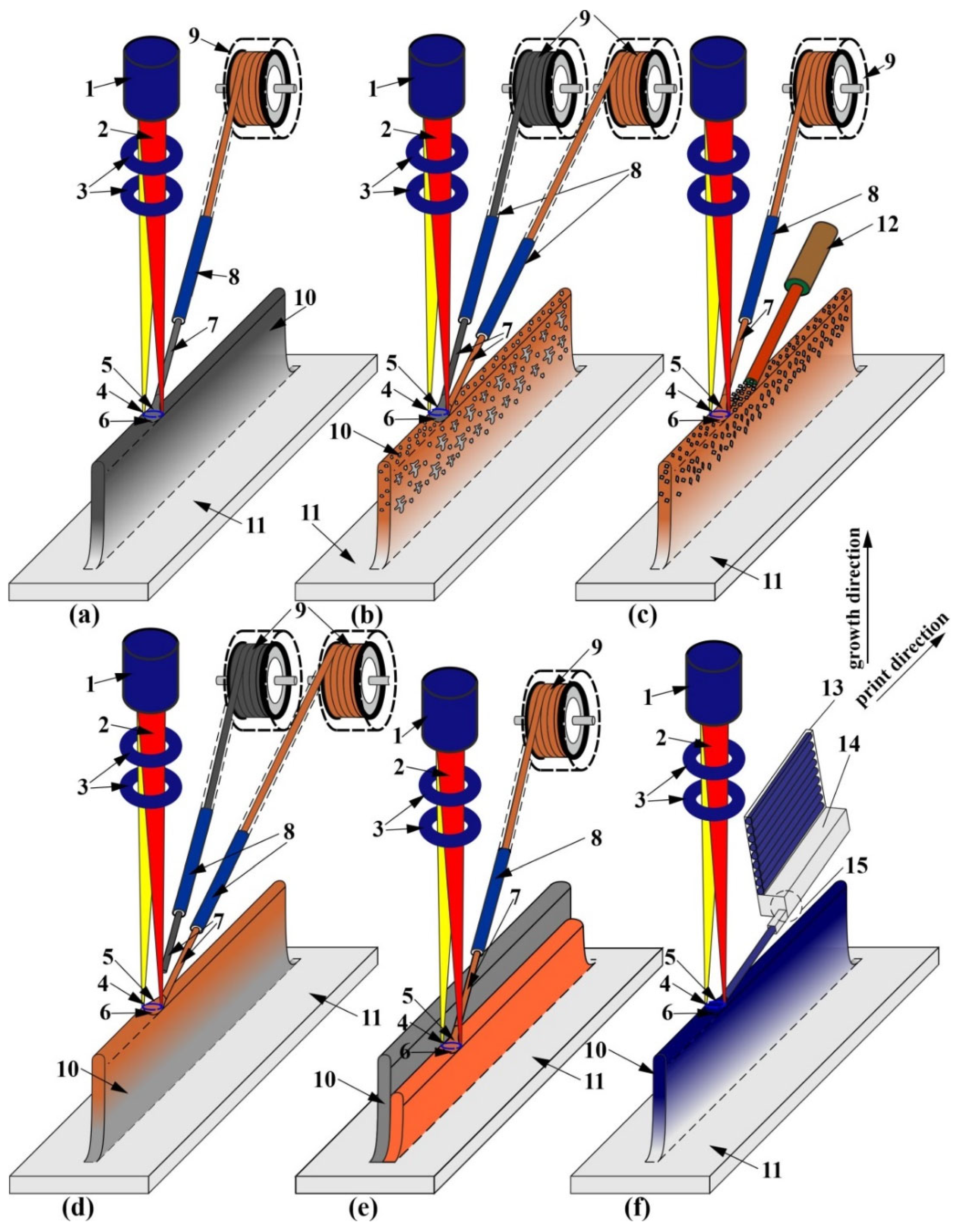
One such method is wire-feed electron beam additive manufacturing (WEBAM) [13]. The WEBAM process uses an electron beam as a source of thermal energy. The energy density, efficiency, scanning speed, and penetration depth, as well as the material layer deposition rate of the electron beam are significantly higher than those of the laser [15,16]. The average deposition rate and layer thickness in the WEBAM process are less than 19.8 kg/h and 3000 µm, respectively. The WEBAM process is also suitable for the fabrication of large-sized parts that cannot be fabricated by powder methods, such as SLM. The electron beam additive manufacturing process includes a vacuum environment to prevent electron scattering, atmospheric pollution, and oxide formation during 3D printing [16,17]. Since the additive forming process takes place in a vacuum, hydrogen absorption does not occur and therefore has no effect. In the literature reviewed to date, no information has been found on hydrogen absorption in the manufacture of products using wire-feed electron beam additive technology. Typical wire diameters for WEBAM range from 0.5 mm to 3.0 mm, allowing a flexible use of the system to form products of different shapes [16]. The quality of the raw wire used has a direct effect on the finished product. The most important characteristic of a wire is that its actual chemical composition matches the specified composition. The wire may also contain technological defects, such as chips, discontinuities, and inflections. These defects do not directly affect the final product; however, they can interrupt the process of additive manufacturing. For example, the presence of chips and inflections can lead to the stopping of the wire feeding system. It is worth noting that such defects do not play a significant role in additive forming, since the wire is completely melted; however, the wire-feed angle may change, resulting in a loss of the specified geometry. However, modern publications do not consider this aspect of wire-feed electron beam manufacturing. Electron beam wire-feed additive printing allows the production of articles made of various metals and alloys, with different overall dimensions, mechanical, and performance characteristics [18]. Different techniques can be used for printing, depending on the material and the desired result. Schematically, the process of wire-feed electron beam additive manufacturing is shown in Figure 1.
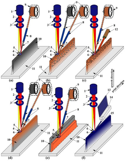
Figure 1.
(a) Schematic of wire-feed additive electron beam production of samples with monometallic, (b) polymetallic composite structure when printing with two filaments, (c) combined wire-powder printing, (d) formation of two-component bimetallic elements when printing one alloy on top of the other, (e) two-row sample production, (f) printing using rod feeder.
Monometallic samples are printed by generating an electron beam (2) from an electron gun (1) through a magnetic focusing system (3) that forms an ellipse-shaped sweep (4) on the surface in the printing area (5), forming a melt bath (6). Wire filament (7) is fed through a nozzle made of heat-resistant bronze (8) from the feeder (9). As a result, a sample (10) is obtained on the substrate (11) consisting of layer-by-layer-deposited material (12), forming a mixed layer (13) on the border with the substrate (Figure 1a). Similarly, composite or bimetallic products are produced according to the scheme shown in Figure 1b. In this case, printing is carried out by the controlled feeding of wires from two feeders, placing the main and additional filaments into the melt bath. The production of composite structures in the surface layer can be performed with the combination of wire and powder feeding into the melt bath (Figure 1c). For this purpose, an additional powder feeder directly into the melt bath or layer-by-layer device (12) is used. By directly controlling the feed rate in the printing process, it is possible to form a gradient transition zone from one material to another (Figure 1d). Such materials can be produced by printing one material sequentially on top of another (Figure 1d) and by printing two parallel vertically adjacent pieces (Figure 1e). This technique is potentially suitable for producing alloys with a controlled structure and enhanced mechanical or performance characteristics. Printing with materials not available as wires is possible using a pushdown bar feeder (Figure 1f). In this case, individual rods (13) are placed in the pushdown (14) of the feeder (15) and entered into the printing area through the feeder. Otherwise, the printing process with the rod feeder is similar to the wire filament printing process.
This review article discusses the basic materials used for additive manufacturing, as well as the structure and mechanical properties of the resulting material. Titanium alloys [19], nickel alloys [20], steels [21,22,23], copper [24], and aluminum alloys [25,26], as well as their combinations [27], are widely used in many industries. These are the materials that this review focuses on. In addition, an emerging area of research into the post-processing of additive products, such as thermo-mechanical processing [28], is also presented in the review, with the example of friction stir processing [29]. Emphasis will be placed on one of the most productive additive manufacturing technologies, namely electron beam additive manufacturing, and technological methods to improve the structure and properties of this technology will be outlined in the paper.
2. Titanium Alloys
Titanium alloys are currently one of the key structural materials used in various industries as they provide high strength and corrosion resistance at low density, as well as a wide range of operating temperatures [30,31,32,33,34]. Because of this, titanium alloys have found the greatest application in the aviation and rocket and space industries, where they are mainly used for the manufacture of engine parts [35,36]. About 80–90% of all titanium alloys used in the structure of aircraft or spacecraft are titanium α + β alloy Ti-6Al-4V [37], and many rocket engine parts made of the alloy Ti-6Al-4V, operating at temperatures below 300 K up to cryogenic temperatures. Despite the many advantages of these materials, there is a problem associated with the high cost of raw materials, as well as the high amount of production waste, which is difficult to recycle [38,39]. NASA and Sciaky, Inc. were the first to attempt to bring additive technologies to the aerospace industry for the manufacture of large-sized products, in particular those made of titanium alloys [40]. The first works on the wire-feed electron beam additive manufacturing of titanium alloys, namely electron beam freeform fabrication (EBAM), were initiated in the early 2000s. A paper by Karen M. B. Taminger and Robert A. Hafley describes EBAM as a new class of rapid prototyping technology that allows the fabrication of titanium alloys based on a CAD model, thereby reducing the need for machining and, consequently, the amount of production waste [40]. Moreover, this technology can be used not only for the production of parts but also for their repair and restoration. P. Wanjara et al. showed that an experimentally simulated recoating of heavily eroded Ti-6Al-4V alloy substrate by the EBAM method allows to obtain the deposited layer by mechanical characteristics comparable with the original part material and meets the requirements of ASTM F2924-14 and ASTM F1108-14 standards [41]. Currently, Sciaky is a major supplier of wire-feed electron beam additive manufacturing equipment and technology for titanium alloy parts to companies such as Boeing and Lockheed Martin. An example is titanium high-pressure spherical tanks, which, depending on volume, are traditionally manufactured by either machining or pressure machining [34]. Naturally, these processes are expensive, material-intensive and extremely time-consuming (it can take from 6 months to 1 year to produce one spherical tank in the traditional way). According to Sciaky, the use of EBAM in the manufacture of titanium spherical tanks reduces the time required to produce a spherical tank by 80%, while reducing production costs by 55% and waste by 75% [42].
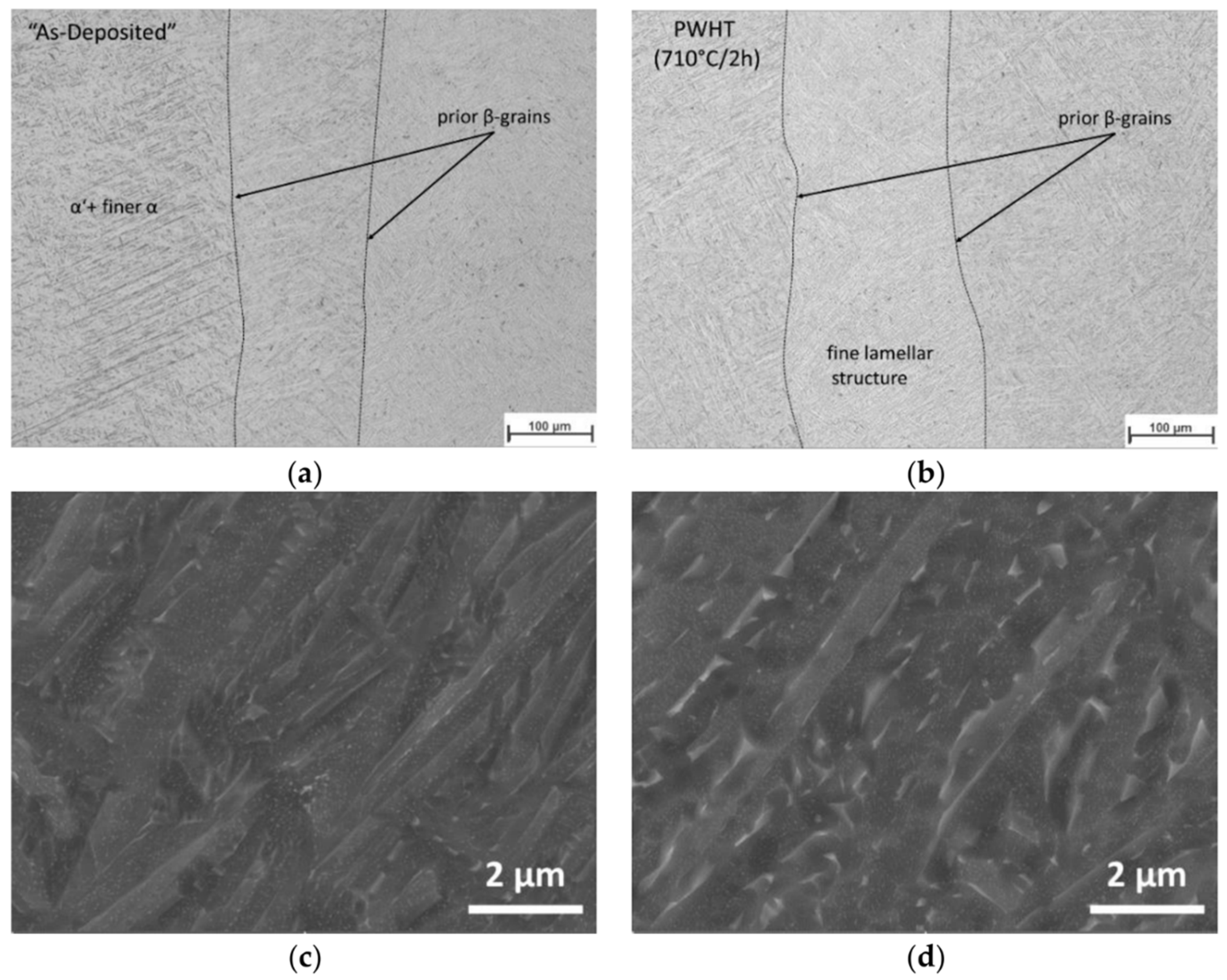
A significant part of the literature is devoted to the study of α + β titanium alloy Ti-6Al-4V. They consider the main features of the formation of this alloy’s macrostructures and microstructures in the process of wire-feed electron beam additive manufacturing. The typical macrostructure for the Ti-6Al-4V alloy is represented by large columnar primary β-phase grains (Figure 2a,b). Within the primary β-grains, a lamellar α-structure is formed during additive manufacturing (Figure 2c,d).
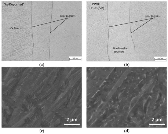
Figure 2.
Microstructure of the AM block center: (a) as-deposited and (b) post-weld heat treatment condition (PWHT); detail of the microstructure by SEM investigations in (c) as-deposited and (d) PWHT conditions [43].
A similar pattern is observed not only in the Ti-6Al-4V alloy but also in other α-β alloys, such as Ti-5Al-2Sn-2Zr-4Mo-4Cr [44].
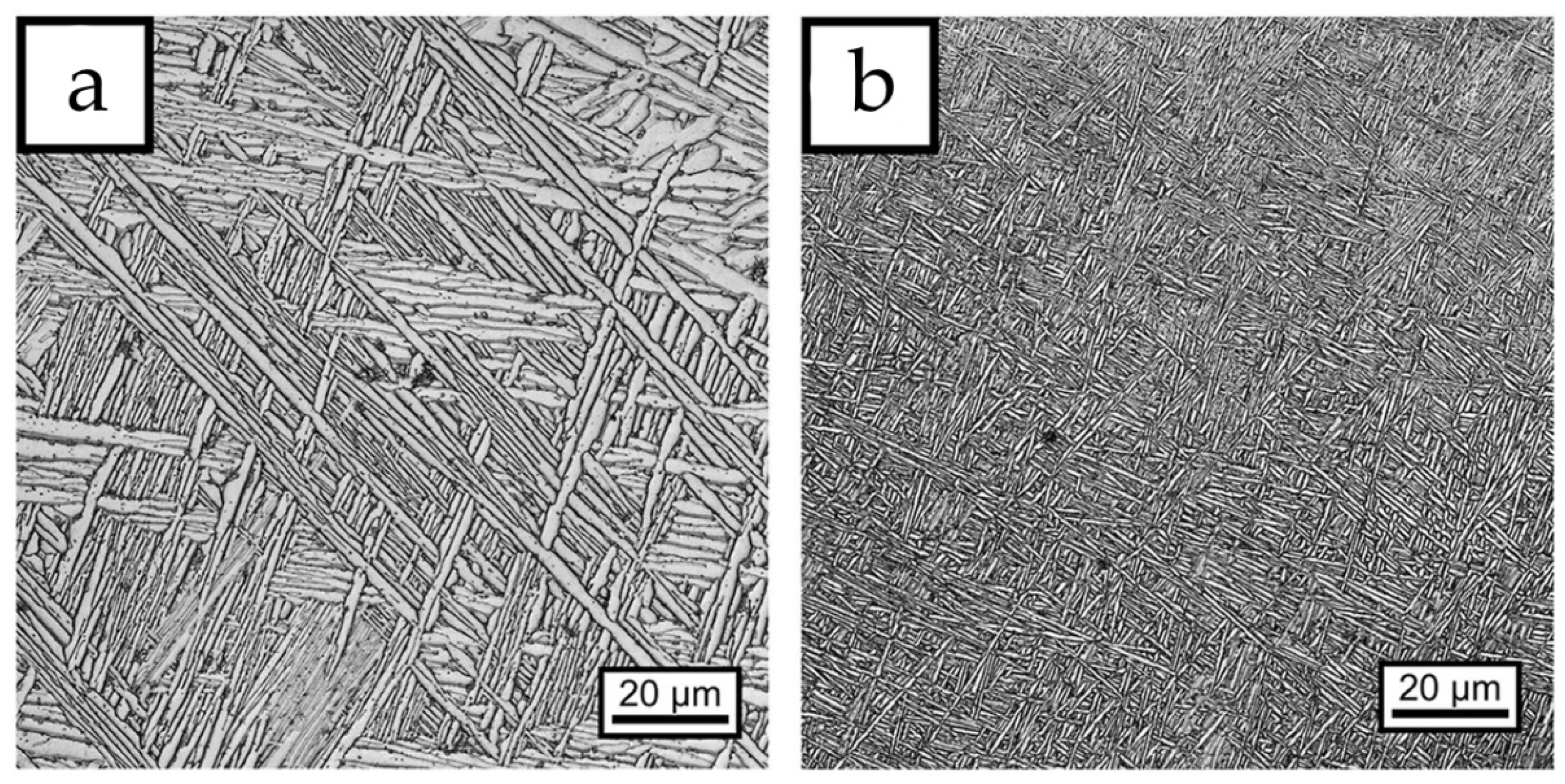
Depending on the selected parameters of the additive manufacturing process and the resulting intensity of heat dissipation in the printing of titanium products, the structure inside the primary β-grains changes significantly. As shown in [45], the α-phase plate thickness can change from 1.7 μm to 0.5 μm with the increasing intensity of heat dissipation through the substrate when its size or chemical composition is changed (Figure 3). Another way to influence the structure formation of the Ti-6Al-4V alloy in wire-feed additive manufacturing is the water cooling of the working table. As was shown in [46], first of all, active water cooling affects the formation of primary β-phase grains: without active cooling, large columnar grains grow, whereas water cooling can reduce the grain size down to equiaxial grains. The residual stresses in the additive samples of Ti-6Al-4V alloy obtained with water cooling are at least three times lower than in the samples printed without cooling.
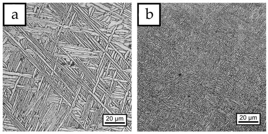
Figure 3.
Microstructure of the additive Ti-6Al-4V printed with (a) low and (b) high heat dissipation intensity (adapted from [45]).
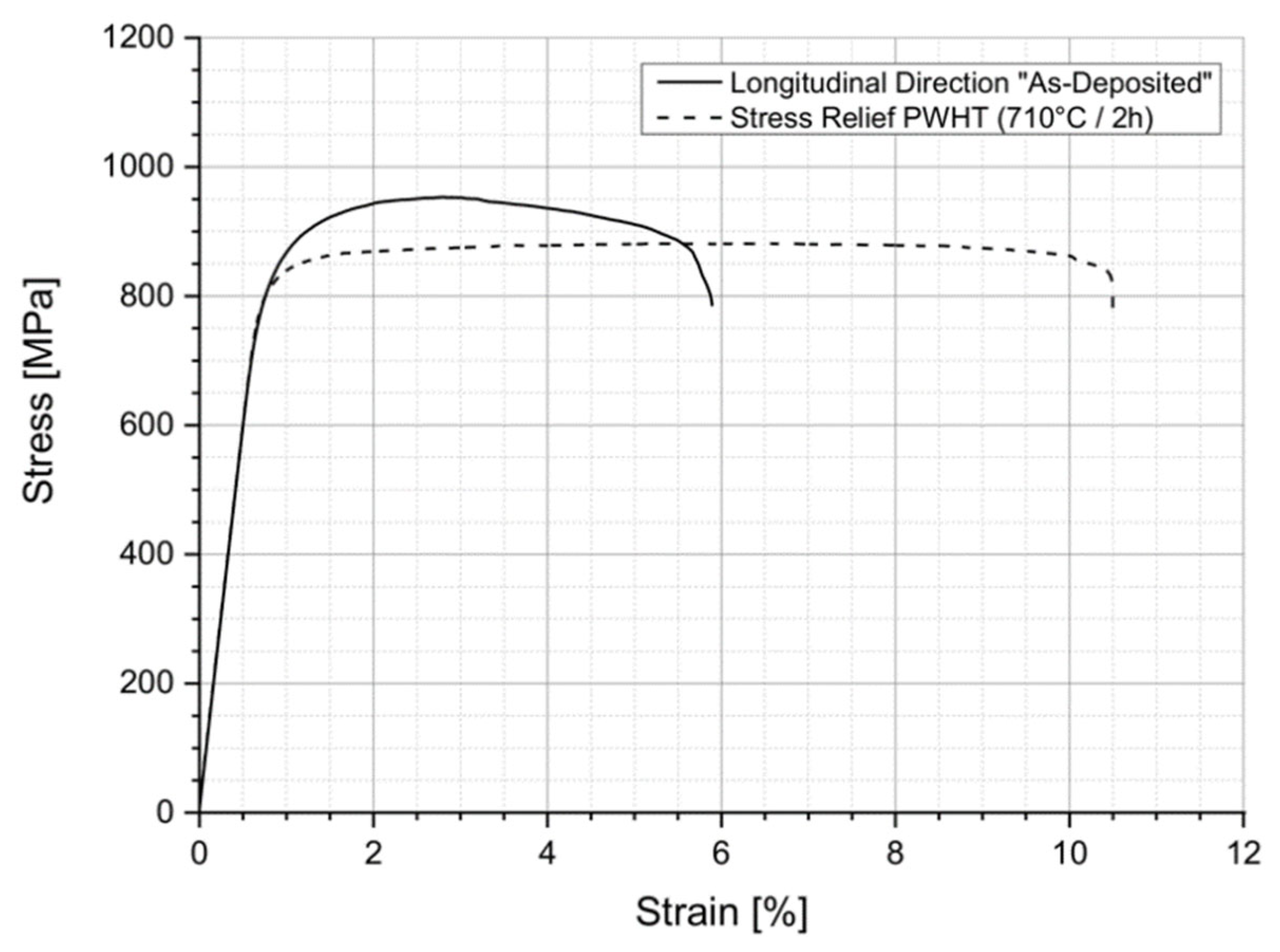
The most debatable characteristics of titanium alloys produced by wire-feed electron beam additive manufacturing are their mechanical properties. This is due to the fact that the strength and ductility of the material are influenced by such parameters as the size and shape of the printed product, the chemical composition of the raw material, and even the size and shape of the tensile test specimens, in addition to the electron beam parameters and cooling conditions [47]. Typically, the tensile strength of an additive Ti-6Al-4V alloy ranges from about 600 MPa in large-sized specimens obtained without water cooling [48] to about 1100 MPa under rapid cooling conditions. The ductility of the material with increasing strength decreases from about 16–20% to about 4–5% [49]. However, ductility can be increased by heat treatment to relieve internal stresses, as was performed in [43] (Figure 4). In such a case, there is a slight decrease in the strength and yield strength, with a more than a twofold increase in ductility.
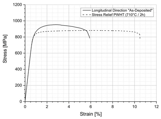
Figure 4.
Stress–strain curves for AM Ti-6Al-4V samples in as-built state and after stress relief heat treatment (adapted from [43]).
Additionally, for parts made of Ti-6Al-4V alloy, friction stir processing can be used for hardening in local areas of the products. This treatment is most useful for large-sized parts printed without active cooling that are characterized by a low tensile strength and can increase the strength of the material by 20–30% [48,50]. This aspect will be discussed in more detail in Section 8 of this paper.
Nevertheless, despite the difficulties in obtaining the correct chemical composition of the alloy and achieving high mechanical characteristics, the wire-feed electron beam additive manufacturing of Ti-6Al-4V alloy makes it possible to form products of almost any shape with minimal machining, which meet the requirements for the performance characteristics of products.
3. Nickel-Based Alloys
Nickel-based heat-resistant alloys (or superalloys) are most commonly used in the production of gas turbine and turbofan engines, as well as in the oil, gas, and nuclear industries [51,52]. Nickel alloys have high values of high-temperature corrosion resistance and mechanical properties. Because of their ability to retain their properties at temperatures close to solidus, these alloys are used in extreme environments at high pressures and temperatures. The structure of high-temperature superalloys is represented by a nickel γ matrix with FCC crystal lattice dispersion-hardened intermetallic secondary phases Ni3(Al, Nb, Mo) and carbides, such as MeC (where in place of Me can be Ti, Nb, W), Me6C (where in place of Me can be Cr, Mo, W), and Me23C6 (where in place of Me can be Cr, W) [51]. During crystallization, undesirable brittle phases may form in nickel alloys based on compounds of the (Cr,Ni)2(Nb,Mo) type. The most common heat-resistant nickel alloys are Inconel 718, 625, 600, alloy 82, IC10, K465, and Hastelloy C276 (the chemical composition of these alloys is shown in Table 1).

Table 1.
Chemical composition of the most common heat-resistant nickel-based superalloys (wt.%).
Traditionally, in the production of turbofan engine disks and the turbine working blades of heat-resistant alloys, the raw material is remelted in three stages then homogenized at a temperature close to solidus to reduce microsegregation [51]. After a series of mechanical treatments (if necessary), the obtained ingots are used to produce the final product. Since nickel alloys are hardened by the plastic deformation process, forging and machining are difficult tasks that require a low process speed and expensive cutting tools [52]. Additionally, in many nickel-based alloys, the combined aluminum and titanium content exceeds 7%, which makes these alloys non-weldable. As can be seen, traditional approaches are expensive in terms of labor and time resources. In addition, these approaches have the following disadvantages: excessive macro- and microsegregation; large primary dendrite arm spacing; and the formation of agglomerations of oxides, nitrides, and large carbides.
The transition to wire-feed electron beam additive manufacturing eliminates some of the disadvantages of the traditional process of obtaining products from heat-resistant nickel alloys. Due to the small size of the melt bath and the localized processes of melting and crystallization, rapid cooling occurs, leading to the formation of a finer and more homogeneous dendritic structure [51]. The degree of macro- and microsegregation decreases, and there is no formation of large carbides. Compared with traditional castings, EBAM alloy 718 products have higher yield strengths but a lower Young’s modulus [53,54].
The shape of EBAM-obtained nickel superalloy products can be thin-walled, bulk, or have a more complex geometry (Figure 5). The microstructure of EBAM-obtained alloy 718 products is represented by dendrites, and regardless of whether the product is thin-walled or bulk, there is a 40 to 60° slope of structure growth towards the movement of the electron beam relative to the substrate [51,53,55]. The formation of the dendritic structure occurs due to rapid solidification of the melt bath. Colonies of small dendrites bounded by a single layer are observed close to the substrate. As the height of the product increases, the size of the dendrites and their colonies increases, and their growth can occur through multiple layers. The transverse size of grains or dendrite colonies ranges from a few microns to 1 mm. In [55], differences in mechanical properties depending on the height of the product were observed due to changes in the dendritic structure, which in turn occurs due to a decrease in the cooling rate. Additionally, in as-deposited state products, the material is textured and, as a consequence, the anisotropy of properties is manifested [53,54]. According to [53], the highest values of the ultimate and yield strength are achieved along the growth direction of the structures, with the lowest along the direction of the electron beam trajectory. It has been shown in [51] that EBAM technology allows reducing the size of primary carbides and achieving their spherical morphology, which increases low-cycle fatigue.

Figure 5.
Geometry and shape of products made of heat-resistant nickel alloys obtained by the EBAM method: (a) bulk [55], (b) thin-walled [56], (c) complex geometry sample [57].
There is a tendency to apply heat treatment to additively formed products. Heat treatment is carried out in the temperature range from 894 to 1464 K with a duration of 1–8 h followed by cooling in air to room temperature or in a furnace chamber [53,54,56]. Thermal treatment can dissolve brittle topologically close-packed phases, reduce microsegregation, and minimize anisotropy in mechanical properties. Additionally, heat treatment promotes the separation and homogenization of hardening γ′- and γ″-phases [56]. In [53], it was shown that recrystallization occurs during heat treatment, which reduces the degree of texture and forms more homogeneous grains with close to equiaxed morphology and sizes of 100–400 μm. The heat treatment of alloy 718 after the EBAM process can increase the ultimate tensile strength and yield strength limits up to 25% and 50%, respectively. In some cases [56], heat treatment leads to the complete disappearance of additive layer boundaries. The microstructure in this case is represented by a bimodal distribution of reoriented small and large grains, which increases the Young’s modulus along the additive growing direction.
It is worth noting that such a combination of material (heat-resistant nickel alloy), heat source (electron beam) and the state of the source material (wire) is not often encountered in the production of an independent product. More often this combination is used in the formation of additive products containing several different materials [57] or when it is necessary to deposit several layers to an already finished product [58].
In [57], a rocket engine nozzle consisting of a copper liner (obtained by an additive method) over which Inconel 625 was deposited using EBAM technology was considered. Such a bimetallic joint is designed to preserve the thermal and mechanical properties of the structure at high operating temperatures. It is noteworthy that [57] did not try to achieve a gradient transition from copper to nickel alloy, which led to the formation of cracks in the transition region due to differences in thermal expansion coefficients. Heating the copper substrate also did not help to get rid of crack formation; however, it led to their appearance only during cooling. It is noted that the fracture occurs not at the boundary of the layers but inside the transition layer. This is attributed to the formation of the CuNi30 phase, the strength of which is 30% less than the raw material.
The need to deposit a small amount of material exists in the chemical, oil and gas, and nuclear industries when it is necessary to obtain a corrosion-resistant coating of weakly alloyed ferritic steel [58]. Studies of heterogeneous materials structure formation can be useful not only for cladding processes but also in the additive formation of nickel products on substrates of more available materials. When additively growing a nickel alloy article on a steel substrate, it is necessary to consider whether the materials are isostructural. If low-alloy steel with a BCC crystal lattice is used, this can lead to the formation of martensite at the transition boundary between the materials, as well as the nucleation of grains with large-angle boundaries [58]. These effects will serve to form stress concentrators, which will subsequently lead to the formation of cracks in the additive product.
In [59], the EBAM technology was considered as a method to restore and harden products. When a single layer is deposited, equiaxed dendrites are formed in its upper part, while in the transition region, predominantly columnar dendrites are formed. As the beam current increases, the dendrites grow and enlarge, and the Laves phase is represented by successive chains of particles. The concentration of niobium (contributing to the formation of the Laves phase) in the additively deposited layer is lower than in the transition region. The degree of niobium segregation increases with increasing beam current. It was also found that the hardness and wear resistance of the additive layer increase with decreasing beam current.
Using the EBAM method, a defect-free bonding of two nickel alloys In718 and IC10 was obtained [60]. This combination improved the plastic deformation capability of the grains, which reduced the residual stress level and prevented crack formation. The microstructure in this case is represented predominantly by oriented columnar dendrites containing carbides and Laves phases in the interdendrite space. Increasing the thickness of the additively formed layer leads to a decrease in the degree of grain orientation and, consequently, to a decrease in the number of low-angle boundaries. However, increasing the thickness of the additive layer reduces the ultimate strength; however, it still exceeds the ultimate strength of the raw material.
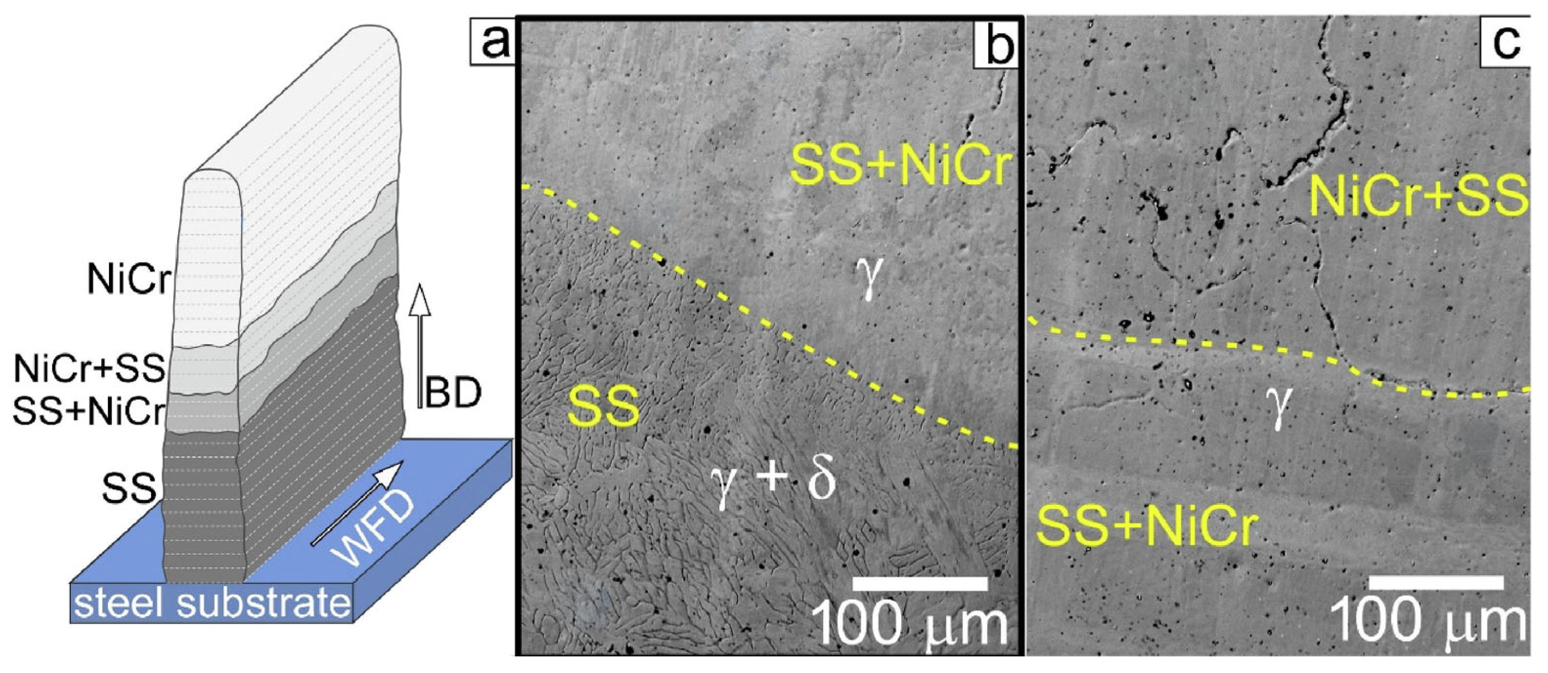
One of the promising directions in the development of additive technologies is the production of functionally graded materials. The EBAM method makes it possible to obtain such materials by simultaneously feeding several wires. In [61], a product with a gradient composition—stainless austenitic steel/NiCr—was obtained. Obtaining composite and bimetallic products will be discussed in more detail in Section 6 of this article.
A comparative analysis of three approaches to the additive manufacturing (direct metal laser sintering (DMLS), binder jet 3D printing (BJ3DP), and electron beam freeform fabrication) of In625 alloy products revealed the following [62]: The structure of the sample obtained by EBAM technology was represented by elongated grains with wavy boundaries and a less pronounced texture compared with DMLS. The product obtained by the BJ3DP method contained chromium oxides, which was not observed with EBAM and DMLS. EBAM had a grain size distribution more similar to BJ3DP than DMLS, although the fraction of grains larger than 1000 μm2 is smaller than that of BJ3DP. The finer grain structure in the case of DMLS indicated a higher cooling rate. In the case of EBAM, the fine-grain size is explained by the rapid crystallization. The wavy nature of the grain boundaries and the significant number of low-angle grain boundaries after the EBAM process may be the result of the “collision” of dendrites during crystallization. The elastic deformation and dislocation density were higher in the EBAM method, which is also related to faster crystallization kinetics. The size and temperature of the melt bath in this case lead to diffusion throughout the bath, as well as in the partially crystallized material, which reaches a temperature of 1000 °C. In addition, the electron beam, unlike the laser beam, creates a heat flux perpendicular to the substrate [62].
In [63,64], the features of the structure formation of ZhS6U (K465) alloy in the EBAM process from the point of view of directional solidification were considered. It is worth noting that it is impossible to obtain wire from this alloy, so rods were used as the raw material. The resulting structure was typical of heat-resistant nickel alloys, namely the directional growth of dendrites in the direction of 3D printing with a slope towards the electron beam motion. It is shown that at the boundary with the substrate (austenitic steel) there is planar growth of structures, in the volume there are cellular and columnar dendrites, and near the surface there is a transition from a columnar structure to an equiaxed structure (CET). Changes in the morphology of the structure are associated with changes in the value of the temperature gradient. As was shown in [63], in the re-melting of an already-crystallized layer, more of the heat removal is due to the thermal conductivity of the material, while a radiation component is present in the new layer. This leads to equiaxial structures on the last layer, while all previous layers have a directional growth of dendrites. The dendrite arm spacing, which depends on the crystallization rate and temperature gradient, is an order of magnitude smaller than for products obtained using the directional crystallization casting technique [63,64]. This indicates a greater value for the temperature gradient achieved by EBAM technology. Since the formation of the additive product took place on a steel substrate, its influence on the chemical composition and crystallographic orientation was evaluated. It was found that, depending on the technological parameters of the EBAM process, the substrate material was mixed into the additive product by 3–8 mm. Dendrites predominantly grew in the direction of the {002} crystallographic plane, despite the fact that the substrate had a rolled texture (i.e., in the direction perpendicular to the additive growing direction lies the {110} group of planes).
The closest technological method to EBAM is that using wire–arc additive technology (WAAM). As in the case of EBAM, Inconel 625, 718, and C276 are the most common materials in WAAM [65,66,67,68,69]. The main difference between these technologies is that in EBAM the product formation process takes place in a vacuum, while in WAAM it takes place in an argon environment. Despite the presence of a protective environment, oxidation can be observed in WAAM products, which is a significant disadvantage [70]. The structure of WAAM-derived heat-resistant nickel alloys is similar to that obtained by the EBAM method: columnar and cellular dendrites growing in the direction perpendicular to the substrate, with an inclination toward the arc-source motion (Figure 6).
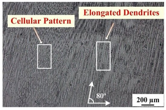
Figure 6.
Structure of the C276 alloy product obtained by WAAM technology [69].
As can be seen from the cited literature data, heat-resistant nickel superalloys are used to make independent products, parts of structures consisting of heterogeneous materials, multilayer coatings, functionally graded materials, and products with a directed structure using EBAM technology. Despite the wide variety of potential applications of nickel alloys in EBAM, there is still a lack of literature data, meaning that it requires future research.
4. Steels
A large number of different steels are processed by additive manufacturing (AM) methods. Techniques that use an electron beam as an energy source, such as electron beam melting (EBM) [71], were originally developed for the machining of tool steel. Now, these methods are also suitable for many other materials. Steel is widely used in a variety of industries, such as oil, nuclear, chemical, bridge, pipeline, building cladding, etc. [72]. This range of practical applications is common due to the large set of different properties characteristic of steel: excellent corrosion resistance, durability, strength, ductility, hardness, impact toughness, and wear resistance, while being low-cost. The different components and phases of the matrix microstructure (austenite, ferrite, martensite) and the various secondary phases (intermetallic inclusions, carbides) give this class of alloy a great variety of microstructural properties.
SS304 is a common austenitic stainless steel with a high Cr content to provide excellent corrosion properties, and the austenitic phase has also resulted in high mechanical properties [73]. For example, the requirement of good resistance to harsh environmental conditions requires the use of stainless steels. Consequently, these steels, particularly SS316L, are used in a large number of applications where the parts to be fabricated are expected to come into contact with corrosive environments at moderate temperatures during operation; therefore, they are used as a material to hold the main structure for the vacuum vessel and other systems in the International Thermonuclear Experimental Reactor (ITER) [74]. Where overlapping corrosion resistance and increased mechanical strength and hardness (compared with austenitic stainless steels) are required, martensitic stainless steels with martensitic-type dispersion hardening are often used (with so-called PH grades such as 17–4 PH and 15–5 PH). These steels are used, for example, in shipbuilding, power plant construction, and pressure casting [75]. Good yield strength and high hardness and abrasion resistance are required in the tool- and die-making industry, for which tool steels are required. Tool steels most commonly used in traditional toolmaking processes contain significant amounts of carbon and are not easily machined, as will be described below, and thus the most popular choice of tool steel for AM machining today is carbonless maraging steel, in particular 18Ni-300 [76]. In addition to these major groups of steels, a number of other, less studied alloys are used in AM. These include, for example, martensitic stainless steels, duplex stainless steels, transformation-induced plasticity (TRIP) and twinning-induced plasticity (TWIP) steels, and oxide-dispersion-hardened (ODS) steels. Functional steel applications, such as custom-shaped parts for electromagnetic applications, require Fe–Si, Fe–Ni, or Fe–Co alloys.
The process of obtaining finished products for practical applications is complex and expensive, and a larger component assembly has a higher risk of failure at the joints. An example of the currently preferred technique for creating individual subcomponents is hot isostatic pressing. However, this procedure involves many steps: machining the backing plates, assembling these backing plates, pre-welding the backing plates with a laser or electron beam, isostatic pressing at elevated temperatures, subsequent machining, and final heat treatment. With such a complex procedure, a defect formed in any of the initial steps can lead to failure in the final component. Therefore, new manufacturing methods are very much in demand for the structural components of future fusion reactors. A key advantage of AM is the ability to fabricate many individual curved cooling parts, resulting in increased performance and product life [77,78]. The AM manufacturing of steels has disadvantages, for example, the austenitic SS AISI 321, 316, and 304 are characterized by residual δ-ferrite after AM machining and heat treatment [61,79]. δ-ferrite is a major source of corrosion [13], so researchers seek to reduce the volume fraction of δ-ferrite in AM products. Thermal treatment or alloying is used to change the morphology and δ-ferrite fraction [80,81,82]. Another problem is related to directional grain growth during AM. More research into additive manufacturing processes for stainless steel is required to meet these challenges.
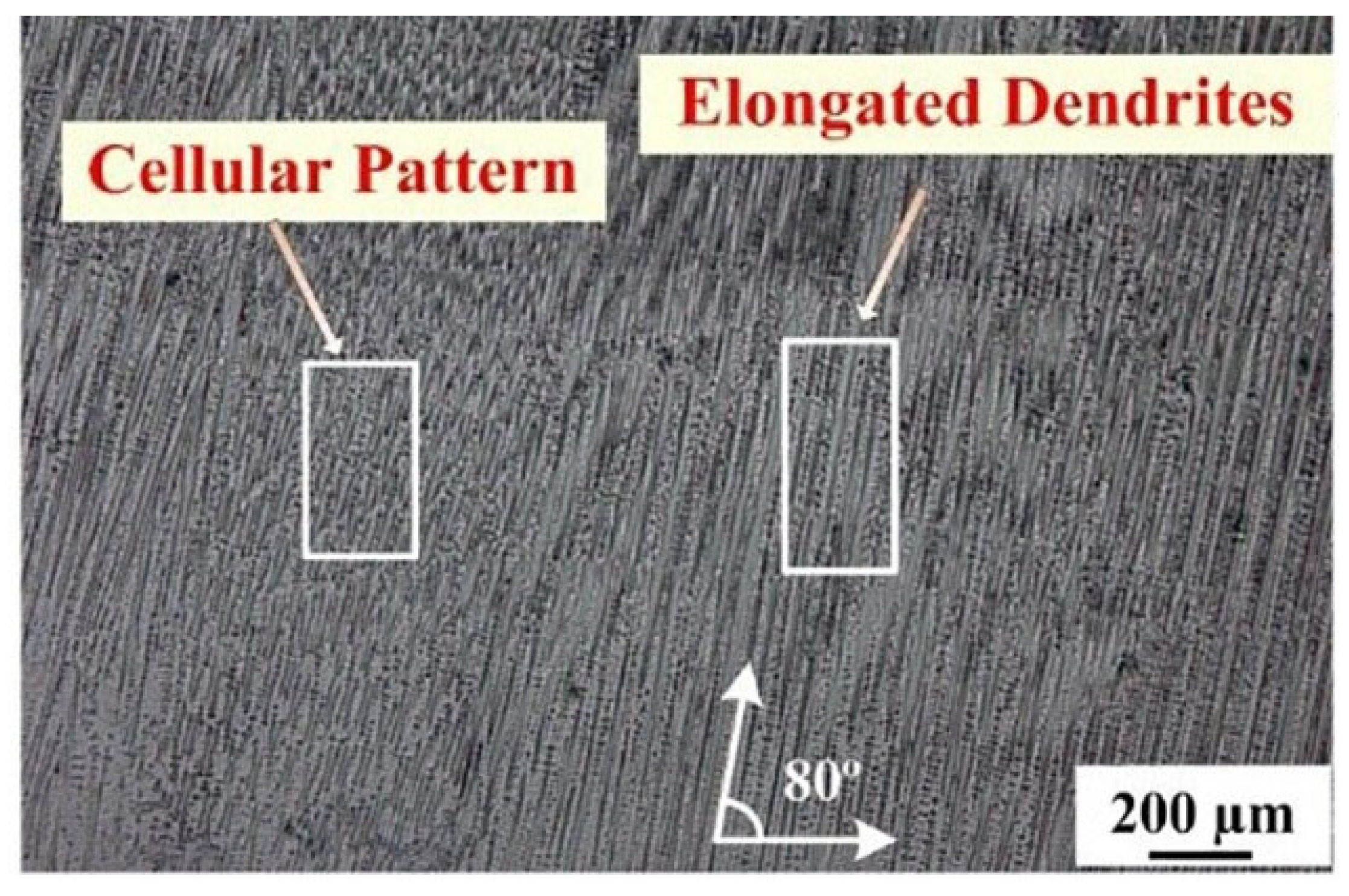
The most common microstructures of AM steels are cellular and columnar. The equiaxial structure is rarely mentioned because of the temperature gradient that promotes the growth of elongated grains during AM. After crystallization, the structure is mostly cells, and the size of the cells increases with the number of printed layers due to heat accumulation during the AM process. The overall columnar microstructure of the growth consisting of dendrite bands, as shown in Figure 7, was visible along the entire length of the sample obtained using the solid wire feed.

Figure 7.
(a) Cross-sectional microstructure and (b) microstructure differences along the height of the sample [83]; (c) traces of the melt bath and microstructure differences in it [84].
It was found that the predominantly columnar grains grew epitaxially in the direction of the temperature gradients (Figure 7a,b), which is inevitably related to the high cooling rate during fabrication. In [85], the EBAM-fabricated samples were characterized by a predominantly austenitic structure with thin ferrite crystallites between the austenitic dendrites, similar to those shown in Figure 8b. The ferrite colonies had different morphologies—vermicular, cellular, lattice, or point-like. The temperature gradient varied along the height of the fabricated sample, hence an inconsistent solid-phase transformation occurred, leading to differences in the microstructure. The columnar dendrites extended in the direction of the temperature gradient. An equiaxial structure prevailed in the upper layers. The difference in the microstructure in different layers can be explained by the solidification rate (V) and temperature gradient (G) during material melting and solidification, where the G/V ratio determines the morphology (cellular/dendritic/equiaxial) [86]. The electron beam AM process uses an electron beam to heat and fuse metal filaments, so the materials melt and solidify locally and quickly. When the first layer is deposited, because the substrate was at room temperature, the temperature gradient (G) is extremely high [87]. Meanwhile, the G/V ratio varies considerably with the direction of growth. Elongated and oriented grains have also been widely reported, depending on processing parameters [88]. As for the melt bath, in which filament melting directly occurs, its boundaries can be clearly seen on the surface. The melt bath is filled with a cellular structure, with an intercellular distance of up to 1 μm (Figure 7b). The authors in [89] showed that large melt baths lead to enlarged microstructures due to slower cooling rates, which also promoted texture due to enhanced recrystallization, while smaller melt baths lead to fine-grained, weakly textured microstructures. The high strength of AM components can be attributed to the combined effect of improved grain characterization due to rapid solidification, dendritic and cellular structures, and a potentially high dislocation density due to rapid solidification and residual stresses [90]. In [91], uniaxial tensile and microhardness tests were used to demonstrate the anisotropy of mechanical properties for additively fabricated austenitic stainless steel specimens. Generally, the yield strength and ultimate tensile strength of austenitic stainless steels are equal or higher in the longitudinal direction [92]. There is little anisotropy in the mechanical properties of austenitic stainless steels among AM samples. The microstructure in these materials is anisotropic in the sense that elongated grains and dendrites are often oriented along the building direction, as this is approximately the direction of the highest temperature gradient during AM processing [93,94]. Additionally, the characteristics of mechanical properties are higher than those obtained by conventional forging technology. The inherent microstructural differences between these AM-produced steels and the traditionally forged steels are incomparable (Table 2).

Table 2.
Comparison of data on mechanical properties of stainless steel under different manufacturing conditions [93,94].
In [93], the averaged hardness profiles measured starting from the interfacial region adjacent to the substrate material was evaluated. No significant changes in hardness values along the height were observed—the average hardness values were (167.1 ± 2.2) HV. The hardness value for the annealed 321 stainless steel sheet (AMS 5510) was 157 HV [90], which is similar to the value determined in this work [93] for the substrate material. For stainless steel 347 (AMS 5512), material data for sheets, plates, or rods indicated values of 167 HV for the annealed microstructure [88], while the 347-type welding wire-feed had hardness values of 150–210 HV [84,89], as well as a post-weld hardness of 169 HV [90]. Nevertheless, AM-produced steels have disadvantages, for example, the austenitic SS AISI 321, 316, and 304 are characterized by residual δ-ferrite after AM treatment and heat treatment [79]. δ -ferrite is a major source of corrosion [13], so researchers desire to reduce the volume fraction of δ-ferrite in AM products. Heat treatment or alloying is used to change the morphology and δ-ferrite fraction [93,95]. Another problem is related to directional grain growth during AM. The use of acoustic waves in the AM process is one of the new approaches to solve the above-mentioned problems. The effect of ultrasonic (US) vibration in metallurgical processes has been known for several decades [96]. Ultrasonic influence during steel solidification, crystallization, and further δ → γ transformation due to the multiple heating of the billet during printing all play an important role in the formation of the structure and the resulting product properties. The results of mechanical tests of the samples are shown in Figure 8.
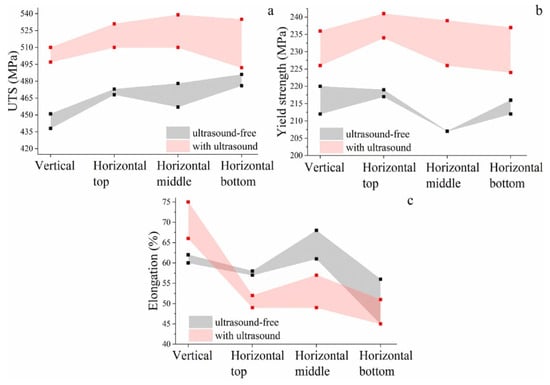
Figure 8.
Ranges of the mechanical properties in AM specimens depending on their position in the billet: (a) the ultimate tensile strength, (b) the yield strength, (c) relative elongation of specimens before failure. These ranges show the scattering of the mechanical properties obtained for three different specimens cut in identical positions in the AM billets [97].
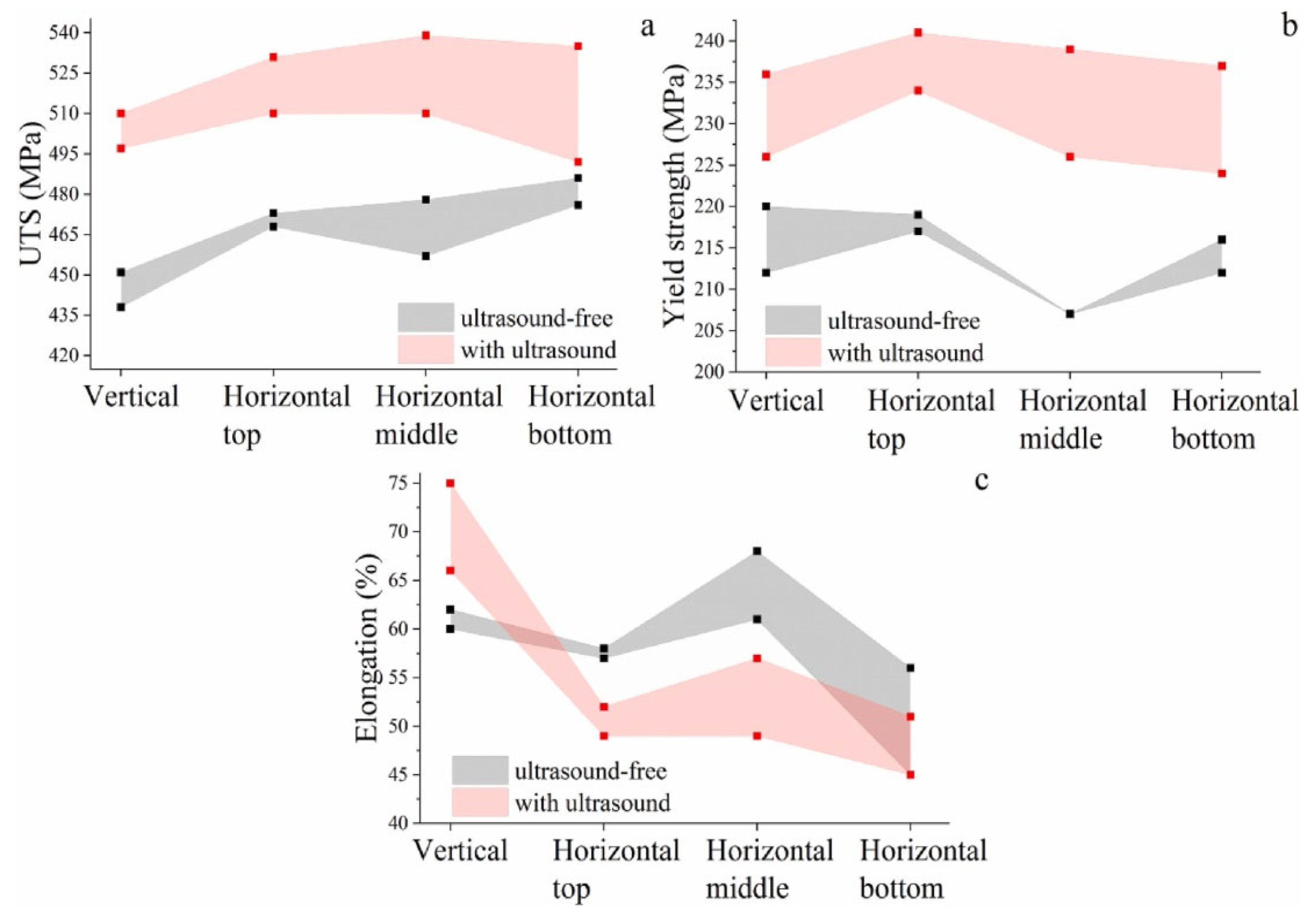
The red and gray shades correspond to the test results of samples obtained by the conventional EBAM method and with ultrasonic vibrations. The strength properties, such as UTS (ultimate tensile strength) and YS (yield strength), are higher for specimens obtained by ultrasonic treatment. At the same time, the ultrasonic treatment decreased the ductility compared with the samples obtained by conventional EBAM.
5. Copper
Copper (Cu) is one of the most widely used construction materials due to its excellent electrical conductivity, thermal conductivity, ductility, machinability, and formability. Due to this, Cu has a wide range of practical applications in various engineering industries, such as automotive, aerospace, electric power, electronics, defense, etc. The high thermal conductivity of copper and copper alloys allows the manufacture of a variety of components, such as heat exchangers (combustion chambers for liquid rocket engines), power units, springs and bearings, electronic connectors, plastics tools for deformation, etc. These high-heat flux environments require a high strength and conductivity alloy to properly cool the thrust chamber walls with high-pressure rocket fuel or oxidizer. The superior electrical conductivity makes copper alloys widely used in the manufacture of thermal transformers, heat sinks, combustion chambers, and other components [98]. The high thermal conductivity of copper quickly removes heat from the melt bath, causing temperature gradients and distortions, thereby leading to faster heat dissipation and a higher localized temperature gradient, which causes the twisting and delamination of the deposited layer [99]. The tendency of Cu to form oxides during processing leads to agglomeration and the reduced fluidity of molten Cu, resulting in the reduced wettability of pure Cu due to copper oxide formation [100]. Thus, pure copper is a material that is still difficult to weld under most ideal conditions. Thus, the choice of traditional fabrication methods, such as welding and its related processes, has a number of challenges. Additive manufacturing is rapidly changing the way many critical products are designed and manufactured, from medical implants to industrial-scale jet engine components and spare parts for aging aircraft systems. The most advanced processes used to manufacture copper and copper alloy products are additive wire–arc manufacturing (WAAM) [101], selective laser melting (SLM) [92], and electron beam additive manufacturing (EBAM) [102,103].
However, all of these processes impose their own specific limitations on production. SLM and WAAM are performed under protective gas conditions and therefore cannot be used to grow products made of highly reactive materials, such as copper, aluminum, or titanium, as it is possible that the molten metal will oxidize at the interlayer boundaries. This would adversely affect both the mechanical strength and the characteristics of the final product. EBAM requires a vacuum so the risk of interlayer oxidation is completely eliminated. EBAM is also more energy efficient than SLM since no high-power lasers are needed to form a stable molten bath. For laser-based PBF AM, the high reflectivity of copper at a typical laser wavelength of ~1 micron requires the use of high beam power, resulting in increased recoil pressure, evaporation, sputtering, and associated defects. Raw materials in the form of copper powder are also extremely sensitive to contamination, especially oxygen, which is difficult to control given the high specific surface area of raw AM powder [104]. Electron beam surfacing with AM wire filament has become the preferred tool for very complex geometries in copper because of its high absorption capacity (compared with laser), and high-speed beam scanning can maintain high powder-layer temperatures. This eliminates the need for tooling and multiple parts and assembly operations. AM reduces complex assemblies to monolithic and mechanically robust structures and opens the door to new advanced high-performance three-dimensional optimized designs, which in the case of current-carrying motor components can lead to significant improvements in packaging efficiency and, ultimately, the power density of traction motors. It has been demonstrated that AM copper using the EBM method makes it possible to produce high-purity components with a density of > 99.95%. As a result, there is growing interest in using this method to manufacture high-purity copper components ranging from complex heat exchangers and welding inductors to vacuum electronics and electric motor components [104,105]. Electron beam wire-feed 3D printing allows the fabrication of layer upon layer of flexible digital construction, offering solutions for fabricating materials with complex geometries and thin sections for C63000 alloys that would be difficult to obtain by traditional casting. As an important type of structural material, C63000 alloys have high saltwater corrosion resistance, excellent wear and abrasion resistance, and good damping capacity (twice that of steels), making them attractive for aerospace, architectural, defense, and commercial applications: marine vessels, oil, gas and petrochemical systems, water desalination and condensation systems, etc. A common requirement for these engineering applications is good mechanical properties combined with strength and ductility to help reduce component weight and improve energy efficiency. In principle, AM processes are similar to welding processes but with dynamic and often stochastic boundary conditions that are subject to complex thermal histories and geometric influences [106,107].
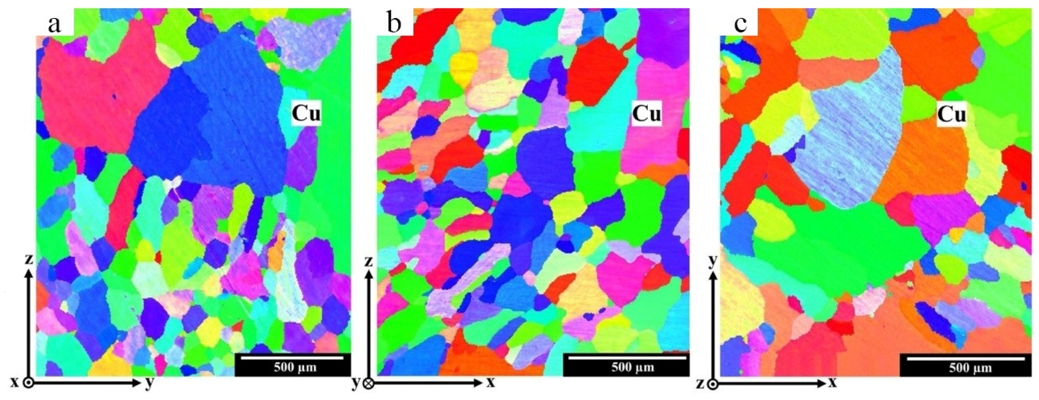
A limited number of studies have been performed on pure metals using AM processes, primarily because pure metals typically have poor mechanical properties. Pure Cu (99.8%) was treated using EBM processes, demonstrating the epitaxial growth of the microstructure. In accordance with the literature data [103], it is known that after the first layers of a fine-grain size, directional solidification occurs in the copper part of the workpiece. This is consistent with the crystallization patterns of many materials using AM and may cause anisotropy of mechanical properties in samples made by 3D wire-printing, as written above. As mentioned above, the G/V ratio has a direct effect on the morphology of solidification. As the G/V ratio decreases, the grains can move from an equiaxed to a columnar shape [108]. Considering the beginning of Cu growth in the lower layers, we can see the presence of equiaxed grains. Moving up to the upper layers, the growth of columnar grains tilted along the printing direction is observed, as shown in Figure 9. The Cu grains have a dendritic morphology. These grains grew in a direction perpendicular to the curing front and opposite to the direction of heat flow.
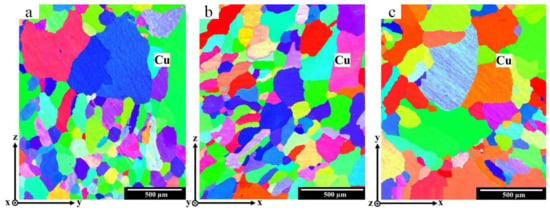
Figure 9.
IPF maps of upper layers of Cu at (a) y-z, (b) x-z, and (c) x-y planes [109].
These variations result in heterogeneous microstructures and properties in different areas of the part. At each location on the part, the microstructure and grain structure of the alloy that is formed after the first thermal cycle is often altered by subsequent thermal cycles. The temperature gradient plays a key role in the morphology and size of the structure and determines the crystallization mode. When the first layers of M1 copper are deposited on a 321 stainless steel substrate, rapid heat dissipation occurs, which entails the formation of a fine-grained structure. As the workpiece grows, the influence of these factors decreases and directional grain growth occurs. Directed grain growth is facilitated by the slow heat dissipation and temperature gradient formed in the additive billet growth process [110]. Many other parameters can affect the process and, consequently, the quality and properties of manufactured components. These include surface roughness, porosity, residual stresses and the associated cracking or warping of components, unique microstructures, and material anisotropy. Thus, the material has a heterogeneity of mechanical properties associated with the structure being formed, consisting of a smooth increase in ductility and a decrease in the strength of the material as it moves away from the substrate [110]. In the finished product, it is important to consider that in the case of 3D printing, there is the anisotropy of mechanical properties. Additional thermal, mechanical, thermo-mechanical post-treatments of additive products are used to prevent the growth of large elongated dendrites. Additional alloying of the original filament is possible to obtain additional crystallization centers in AM, and by using additional interlayers of dissimilar materials, polymetallic materials of two or more metals can be created.
6. Aluminum Alloys
The production of aluminum alloys by wire-feed electron beam additive manufacturing is an urgent task. However, at present, there are very few studies in this field, unlike other additive manufacturing methods, such as WAAM, LD (laser deposition), or DED (directed energy deposition) [111,112,113,114]. Printing in a vacuum chamber, the possibility of continuously adjusting the heat removal, and obtaining various composite materials using a two-wire printing technique makes the electron beam technology applicable for printing aluminum alloys along with electric arc wire or laser technology of directional energy input.
However, printing using wire-feed additive electron beam technology is also associated with the implementation of a number of additional processes not observed with printing using the above-mentioned technologies. The main difference with printing in a vacuum with relatively low heat dissipation from the material is the longer lifetime of the melt bath and the effect of the low pressure around the melt bath on the structure and properties of the material. This leads to increased burnout of individual chemical elements due to evaporation from the melt bath. In [115], a method of thermal management of AA5356 aluminum alloy printing by electron beam additive technology was worked out. The authors revealed that at high heat input (kJ/mm) due to the electron beam power maintained throughout the growing sample, the overheating of the material occurs by its upper part. The overheating is accompanied by excessive spreading, disturbance of the microgeometry, and depletion of the aluminum alloy by magnesium. If the heat input is low during the growth of the whole sample, large defects form at the border with the substrate, and the geometry of the sample is disturbed due to the rapid cooling of the material deposited on the underheated substrate. The optimal control scheme for printing was an exponential decrease in the beam current (hence the heat input), resulting in an increase in the height of the sample. This made it possible to get rid of the mentioned defects. Additionally, an increase in the porosity of the surface layers of the material after printing at high or low values of thermal investment was detected. Obtaining large blocks shows that if the values [116] of the printing process parameters deviate from the optimal microgeometry disturbances, the formation of large defects between individual columns or rows of the applied material, in addition to the formation of pores, is possible. The application standard for most scanning strategies leads to a distortion of the sample shape, namely a slope of the most strongly heated part of the block. The anisotropy of the structure of the aluminum–silicon and aluminum–magnesium block samples shown in [117] is different. The aluminum–silicon alloy A04130 is characterized by low differences in the values of the tensile strength and yield strength, not more than 5–6%, and quite significant changes in ductility in the order of 35–38%. The highest ductility is typical for samples cut in the printing direction, while the lowest is typical for samples cut in the growing direction. The AA5056 alloy is characterized by slightly larger differences in ultimate strength of up to 11–12% and smaller differences in ductility of up to 25–29%. For this alloy, the highest strength and ductility are characteristic of specimens cut in the printing direction. In general, these alloys after printing are characterized by low values of mechanical properties (the ultimate strength of samples of alloy AA5056 is 175–200 MPa, while alloy A04130 is 170–180 MPa). Thus, for aluminum alloys after printing, it is possible to distinguish high-plasticity and low-strength values due to an increase in grain size due to the alignment of the thermal gradient and low rate of heat removal in comparison with other methods.
7. Polymetallic Composites and Bimetallic Elements
In the modern literary sources, one can distinguish a sufficiently large amount of information on the printing of functionally graded materials by the direct energy deposition (DED) method based on the fusion of powder fed in a jet of inert gas by a laser beam. In [118], an overview of the current state of the problem in the field of multi-metal composites production by the DED method is presented. For this direction of research, we can highlight significant groundwork and prospects for future development, as well as common defects created with wire additive technologies (as will be shown later) when printing at the junction of heterogeneous materials.
The number of studies devoted to the production of materials by additive technologies using wire filaments is significantly less. At the same time, the most elaborated branch in this case is the obtaining of polymetallic products by wire–arc additive technology [119]. A wide range of works on obtaining Fe-Ni materials [119,120,121,122,123,124,125,126], functionally graded materials based on titanium aluminides [127], and products based on bronze and steel [128], etc., can be highlighted.
The least represented technology of additive manufacturing with a directed supply of material and energy into the printing zone is wire-feed electron beam additive technology when forming products with functional-gradient and polymetallic structures. This technology is one of the most acceptable for the production of composite, functionally graded materials and bimetallic products from materials based on copper and steel [129]. Electron beam 3D-printing successfully produces functional-gradient transitional structures, with a smooth transition from one material to another [130], showing the high mechanical properties of the gradient zone. Products with a sharp gradient from copper and steel are also produced [103]. It is also possible to obtain layered composites with alternating layers of copper and steel. High values of mechanical and operational properties can be obtained by printing polymetallic products based on aluminum and titanium alloys [131,132,133], as well as copper alloys [134,135,136,137,138]. It is also possible to obtain bimetallic-graded products from steels and nickel alloys [61], as well as from nickel alloys and copper alloys [139].
7.1. Polymetallic Composite Materials and Bimetallic Elements of the Copper–Steel System
In recent years, an increased interest in the design and manufacture of products (polymaterials) made from multiple materials that offer different properties (e.g., mechanical, thermal, electrical), weight optimizations, and cost savings has been observed. Such products can take full advantage of the unique properties of each material from which they are made. This can change the traditional manufacturing paradigm in which a part is usually made from a single material, with some properties being sacrificed. Copper/steel is a typical bimetallic functional material that combines the excellent electrical and thermal conductivity of copper alloy with the high strength and hardness of stainless steel. This poly material is very attractive because the resulting product can simultaneously utilize the best properties of copper and steel, including the corrosion and oxidation resistance of stainless steel (SS) [140]. As a consequence, copper and stainless steel hybrid parts are widely used in the electrical power industry, nuclear industry, heat exchangers, automotive industry, electrical and electronics, etc. [141]. To meet the requirements for the increased heat transfer of technical components, such as heat exchangers, cooling channels in mold inserts, transformers, gas turbines, etc., complex-shaped materials with high thermal conductivities are required [142,143]. Typically, complex-shaped copper/steel-based products are fabricated using joining processes, such as explosion welding [144], laser welding [145], electron beam welding [146], diffusion welding [147], and other conventional methods [148]. However, it is very difficult to make a quality joint between copper and stainless steel because they retain significant differences in physical, chemical, and thermomechanical properties. For example, in [140], the authors examined the limited solubility of solids and formed liquid separations at higher cooling rates. Recently, there has been interest in the production of copper and steel bimetal using laser additive manufacturing technologies, such as selective laser melting (SLM) and directed energy deposition (DED) [149]. Compared with traditional welding technologies, AM technologies have the advantage of good metallurgical coupling [150], shortening the manufacturing cycle time and reducing the cost of production. Some of the literature focuses on the production of copper alloy parts on a steel substrate using SLM technology. In [151], the authors used SLM technology to fabricate UNS C18400 alloy on a 316 L stainless steel substrate, obtaining a good metallurgical bond at the steel/copper interface. In many cases, it is necessary to fabricate a steel part on a copper alloy substrate, such as a crystallizer in a continuous casting process. However, researchers examining copper/steel bimetals are still trying to find a way to achieve crack-free fabrication. The extremely low laser absorption capacity (~2%) and high thermal conductivity (400 W·m−1·K−1) T provided by the copper alloy substrate means that a large amount of energy is required in the fabrication process. In addition, the large differences in the thermal expansion coefficient and crystal structure between Cu and Fe result in inappropriate deformation and high stress at the interface, which can eventually lead to cracking [150]. Additionally, the fabrication process is quite complicated because of the high reflectivity and differences between the thermal conductivity values of these dissimilar metals. In [149], H13 steel on a copper substrate was fabricated using the SLM technique, and the authors found that a good bond with appreciable interfacial diffusion could be obtained. Paper [150] investigated the mechanical characteristics of a copper/steel bimetal compound obtained by SLM technology. For example, in [101], laser-welded SUS304 with T2 copper was investigated, with cracks reported along the liquid grain boundaries in the heat-affected zone. Such cracks were also observed in SS316L-copper, SS321-Cu, SS201-Cu, and SS304-Cu welds [152,153,154]. The authors of [140] reported microcracks in the fusion zone of SS316-Cu compounds formed by electron beam melting due to the heterogeneous composition and residual stress distribution in the fusion zone. Segregated copper in the mixing zone causes greater inhomogeneity and thermal stress, which leads to the appearance of more microcracks. The listed studies show that the copper/steel bimetal interface is prone to cracking. Liquation cracking in the heat-affected zone when steel is joined to copper is also a detrimental problem [101]. In addition, the large differences in thermal conductivity and the coefficients of thermal expansion between copper and SS can lead to large residual stresses around the joints, which leads to cracking [139]. Many previous studies have reported that heterogeneous copper/steel joints are prone to defects due to the above problems.
In the last couple of years, however, researchers have succeeded in creating a defect-free bimetallic material based on steel and copper by AM methods, creating a sharp [155,156] and a smooth interface [157,158] between them. One of the features of forming a defect-free interface is the phase separation along the transition zone—α-phase grains were distributed as a volume on the first copper layer [111,157]. The distribution of iron in the first copper layer was rather non-uniform, as in previous studies [141,156]. Figure 10a clearly demonstrates that the α-phase grains had a globular and dendritic morphology, which was non-uniformly distributed on the copper. The α-phase grains solidified mainly from the liquid phase because of the melting temperature difference between iron and copper.

Figure 10.
SEM images for the first copper layer: (a) low magnification image, (b) dendritic morphology, (c) globular morphology [157].
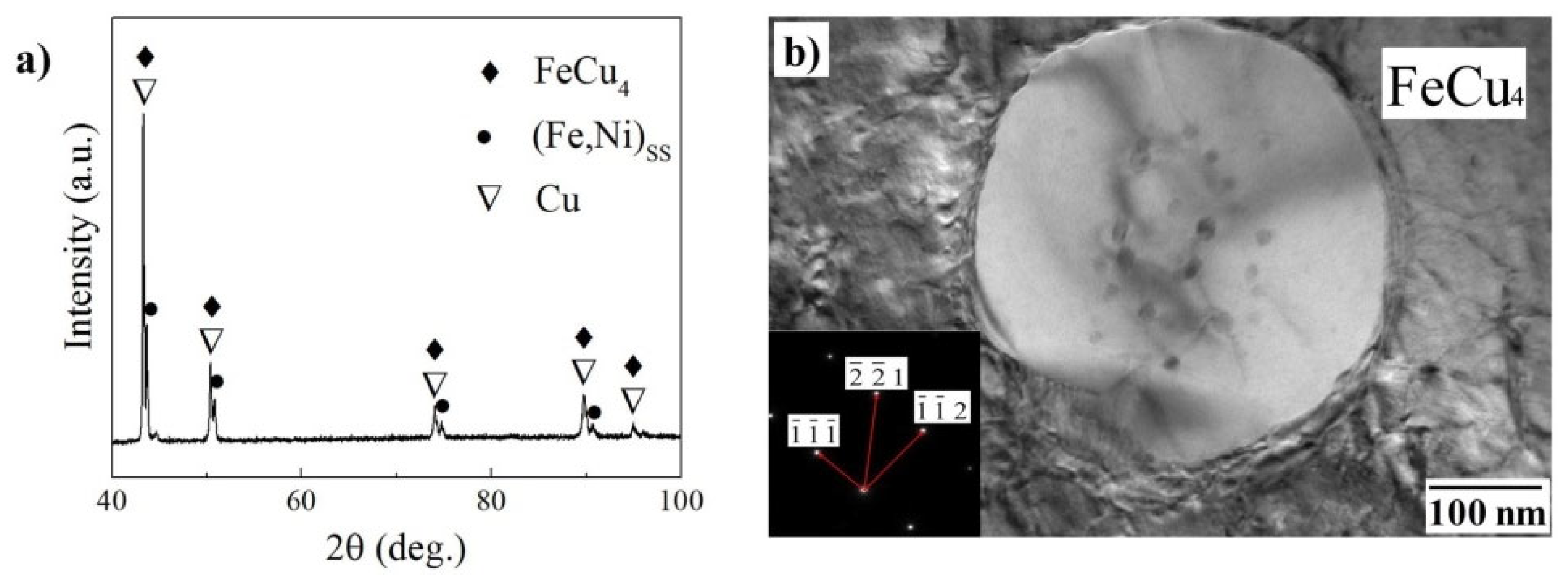
The solubility of iron in copper gradually decreased with cooling, then the iron atoms were collected at the corresponding crystal face and transformed into a dendritic α-phase, as shown in Figure 10b. Copper atoms would be deposited within the globular phase due to the fact that the solubility of copper in iron decreases with cooling, as shown in Figure 10c, which is similar to the EBW process [110,145]. It is shown that point A (Figure 10c) consisted of ε-phase, with 93.3 at.% copper content. Point C was also ε-phase but located in globular α-phase and the copper content was 55.5 at.% while the iron concentration increased to 30.3 at.%. The iron concentration at B and D is almost unchanged, while the copper composition at D has decreased due to deposition of the supersaturated ε-phase. The resulting microstructure consists of very fine nodular dark chromium-rich particles that are evenly distributed in a bright copper matrix. The high cooling rate is known to allow the CuCr liquid to enter the miscibility gap, where liquid phase separation occurs. Under these conditions, each separated Cr liquid phase has a high tendency to form a spherical shape to minimize individual surface energy. Subsequently, rapid cooling could suppress the growth of small spherical Cr particles and lead to spinodal decay. In papers [159,160], the authors presented monotectic phase diagrams for the Cu-Cr system along with the Gibbs energy of the supercooled Cu-Cr liquid at 1500 K, which demonstrates spinodal decay at high cooling rates (x ≥ 104 K/s). In addition to the refined microstructures, a fine dispersion of copper-rich dots was found to exist in some portions of the chromium-rich phases, as shown in Figure 10b. The reason for this phenomenon is twofold. First, the supersaturation of Cu in the Cr phase due to rapid cooling conditions, which is observed when CuCr alloys are rapidly solidified by melt forming or melt quenching [161]. Secondly, kinetic effects due to different Cu and Cr diffusion coefficients. It has been reported that the diffusion coefficient of Cu in BCC-Cr is about two orders of magnitude smaller than that for Cr in Cu FCC phase [162]. Consequently, compared with the rate at which Cr atoms migrate and initiate nucleation, the displacement of Cu atoms from the BCC chromium-rich particles takes longer. Compared with previous copper–steel fusion welding studies [110,154,159], not only were Fe-Cu solid solutions present when the layers were directed, but metastable FeCu4 phase particles were also detected (Figure 11).
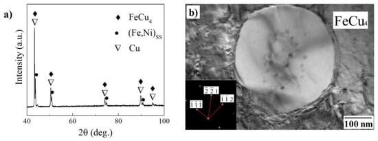
Figure 11.
XRD results and TEM images for the first copper layer. (a) XRD results of the deposition, (b) morphology of FeCu4 [128].
As the number of layers increased, the heat transfer was limited to the inside of the previous layer. In addition, the thermal conductivity of SS was much lower than that of copper. This resulted in a lower cooling rate during EBAM than in conventional copper and 304 stainless steel welding. Consequently, the ordered transition of iron and copper occurred at a low cooling rate. Interfacial interaction occurred in the boundary regions in both copper and iron: Cu particles with an average size of <5 µm were formed immediately near the sharp boundary of the boundary zone in the region of the iron matrix, whereas Fe particles with an average size of <10 µm were formed in the copper matrix. Different mechanisms of boundary formation during 3D printing, namely the filament change of stainless steel and copper, have been established: during the formation of the steel–copper boundary, austenite hardening by copper occurs; during the formation of the copper–steel boundary, spinodal decomposition is observed [156]. Samples showed a sharp transition boundary rupture in the Cu region, and this is expected because Cu is a soft material and is primarily subject to the accumulation of a large amount of strain followed by its high-degree localization. Because the UTS of Cu is low, the stress did not cause much deformation in the steel. Based on the level of mechanical properties, the UTS and relative elongation achieved by the steel–copper sample were 298 MPa and 10%, respectively. The UTS and relative elongation values achieved in our studies were 99.55% and 33% of the basic Cu material, respectively. It is believed that the low % elongation is due to small internal defects (porosity or cracks) in the dissimilar material joint, and therefore defects in the Cu layers can develop significantly during the tensile test, leading to premature failure. Although the steel–copper specimen exhibits a relatively lower percentage of elongation than the base Cu material, the other tensile properties (ultimate strength, fracture strain) are almost identical in magnitude to the base Cu material [163]. The reason for the high bonding strength of the materials at the interface appears to be due to their internal structure. Thus, in [155], the boundary regions of the “steel–copper” bond in the layers of similar “copper–steel” samples studied in this work were studied in detail. It was shown that the structure of the metal in the boundary zone is represented by a mechanical mixture of copper and austenitic steel. The steel–copper interface has a wavy structure and is completely devoid of any microscopic defects, such as large porosity and hot cracks.
In the case of bimetallic samples with a smooth transition from steel to copper, the mechanical properties lie in the interval between steel and copper. For example, in [153], the strength of CuSn/18Ni300 bimetal (144.1 ± 41.59 MPa) is much lower than that of the CuSn sample (441.0 ± 7.048 MPa), and the failure occurs at the interface. The final tensile strength in the perpendicular tensile direction to the 316L/C18400 bimetal interface is (310 ± 18) MPa; however, there are no tensile results in the parallel direction to the sample boundary. In the case of a sharp transition boundary from one material to another, strain dominated in the Cu region. This is expected since the strength characteristics of Cu are much lower than those of SS. That said, the YS and UTS of Cu fabricated with AM are superior to other conventional methods due to the achievement of quality and defect-free samples. This is significantly influenced by the mechanism of the microstructural evolution of the gradient zone of the Fe-Cu polymetallic alloy. The formation of the gradient zone can be divided into the following four stages: (I) Formation of the mesh structure; (II) grouping of elements near dendritic boundaries; (III) formation of a sharp boundary between Cu and Fe; and (IV) the formation of nanodispersed particles [158].
7.2. Composite Materials Based on Copper Alloys
Only a small number of scientific groups are currently engaged in obtaining this type of composite material. The main areas of work are in obtaining composite materials on the basis of aluminum bronzes by adding an additional filament of steel or nickel alloy into the melt bath during printing or the introduction of powders of different compositions during the hybrid wire–powder method of obtaining the samples.
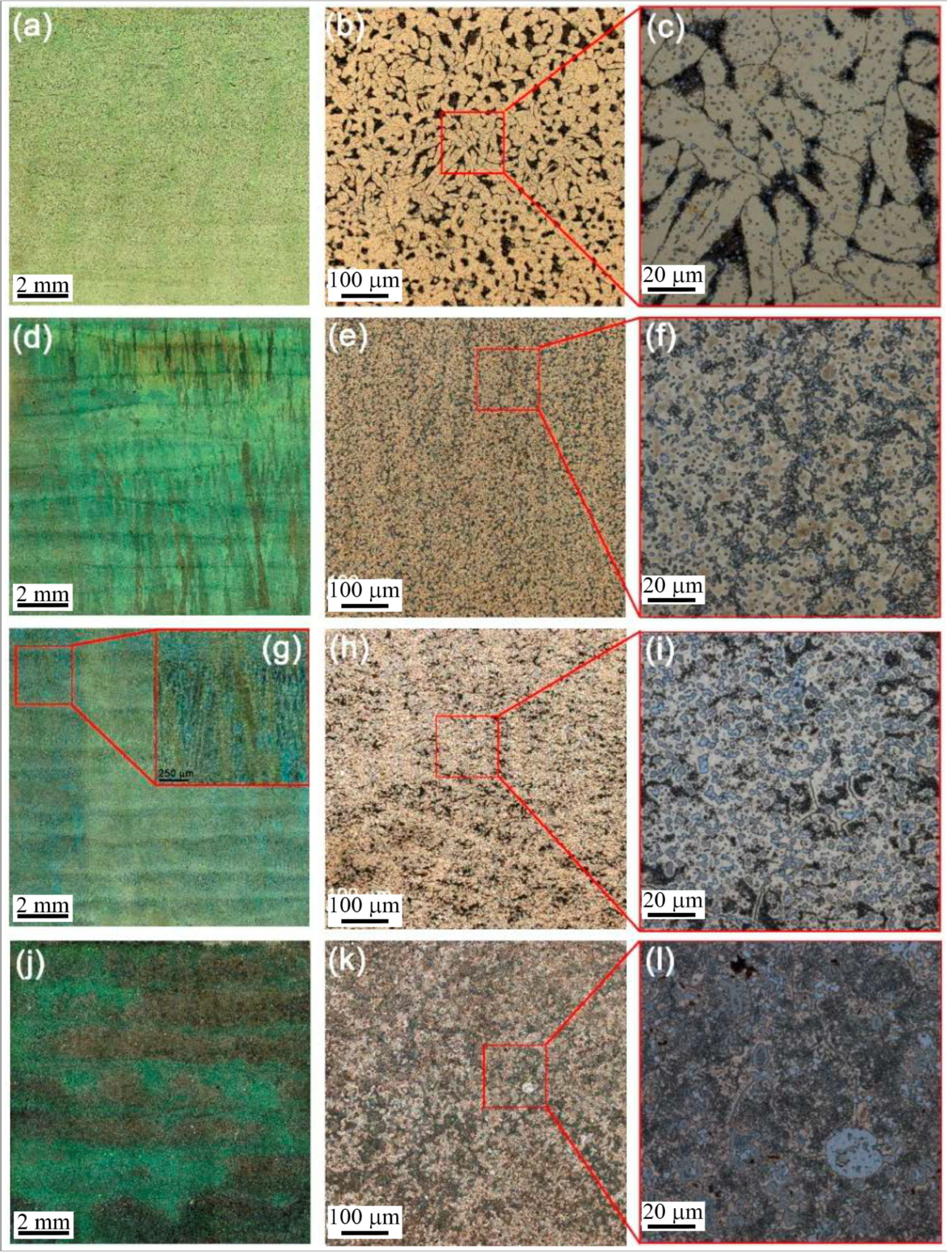
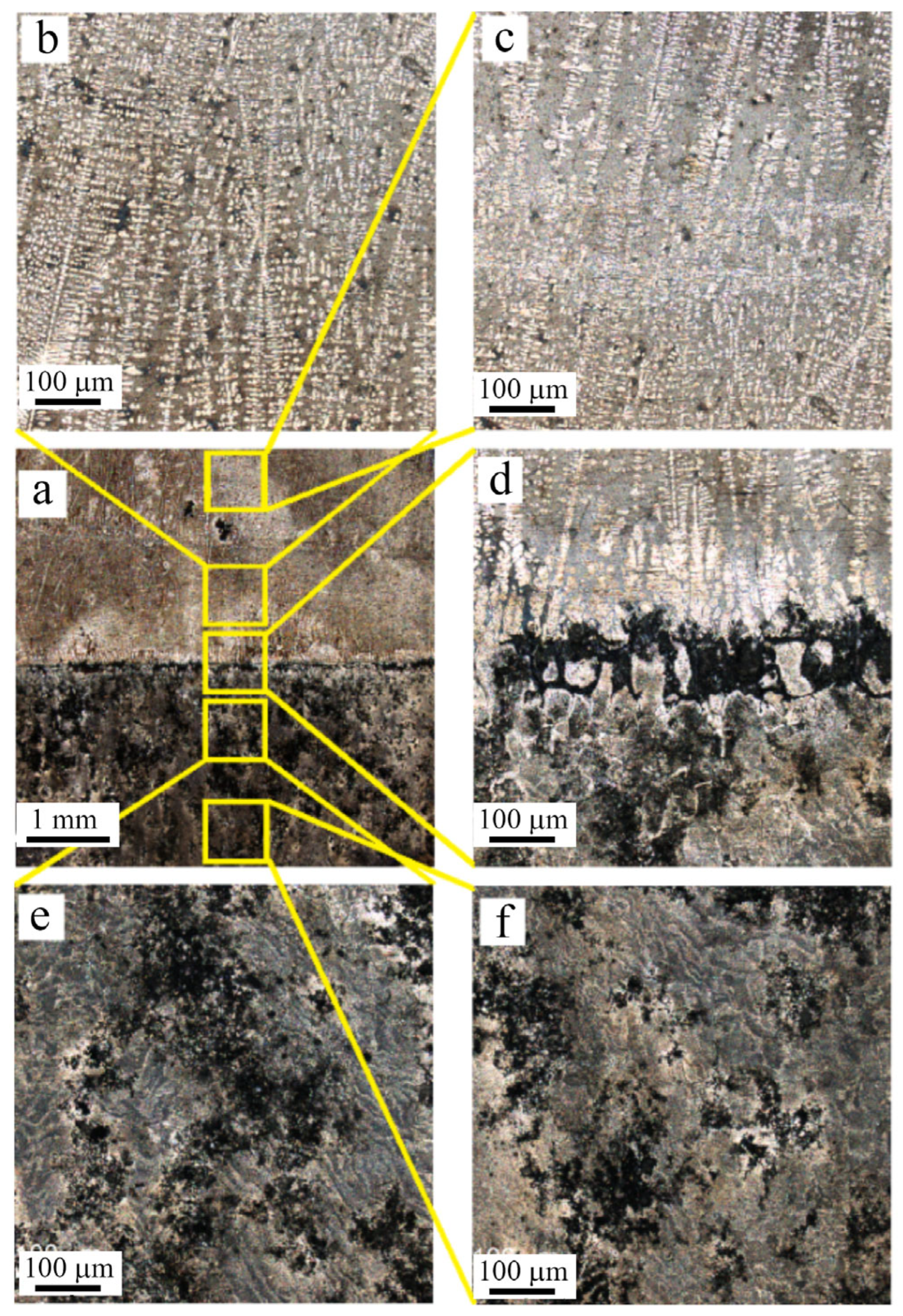
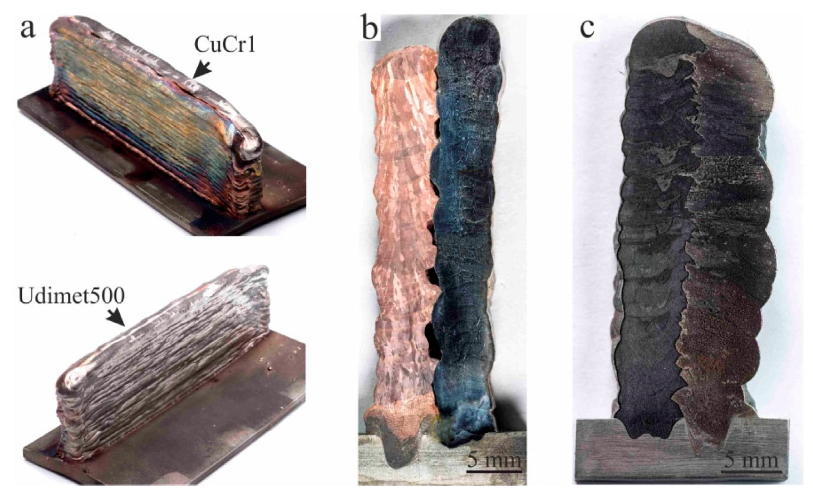
In [133], the authors used the EBAM method and obtained thin-walled samples of CuAl9Mn2/Udimet 500 composites with different Udimet500 nickel alloy contents (5%, 10%, 15%, and 25%) by simultaneously feeding and fusing two wires: bronze and nickel alloy. The authors found that increasing the nickel alloy concentration results in a marked decrease in relative elongation from 33% for 5% Udimet 500 to a fully brittle fracture for 25% Udimet 500, with the ultimate strength increasing from ~590 MPa for 5% to ~680 MPa for 25%. Microhardness increases from 1.7 GPa for 5% to 2.6 GPa for 25%. The structure of the samples after printing has a complex and heterogeneous character, with the presence of a whole spectrum of particles of intermetallic phases or mixtures of refractory metals (Figure 12). The formation of particles with a core–shell structure is noted. As the nickel alloy input increases, the volume fractions of intermetallide phases, fragments of unreacted nickel alloy, and refractory metal particles increase, while the volume fraction of the bronze matrix decreases. At a nickel alloy content of 25%, the heterogeneity of the material structure increases sharply, and a large number of large particles of nickel alloy with secondary phases in the structure is formed.
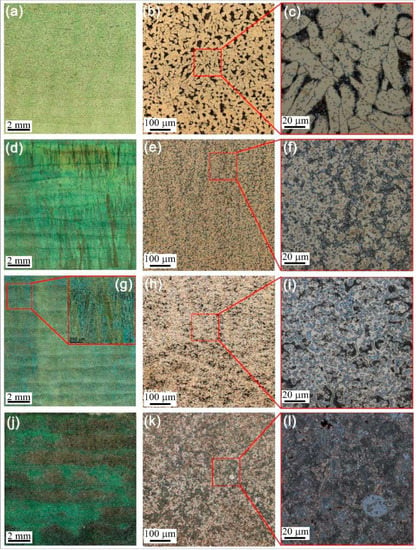
Figure 12.
(a–c) Microstructures of the 5% Udimet500, (d–f) 10% Udimet500, (g–i) 15% Udimet500, (j–l) 25% Udimet500 alloys [133].
In [137], the authors studied the possibility of obtaining multimaterials consisting of aluminum bronze CuAl9Mn2 and nickel-based superalloy Inconel 625 by two-wire electron beam additive manufacturing, with 5%, 15%, 25%, and 50% Inconel 625. It was found that increasing the concentration of the nickel alloy leads to an increase in microhardness from 133 to 164 MPa at 5% Inconel 625, to 414 MPa at 50% Inconel625. The microstructure of the material obtained in the work, when changing the concentration of In625 from 5% to 50%, undergoes significant changes. For example, at 15% Inconel 625 in bronze, the allocation of needle-like particles is observed, as well as an almost complete suppression of high-temperature phase β’.
At 25% Inconel 625 there is an increase in the previously described particles, and at a concentration of Inconel 625 50%, there is the formation of dendrites, the main component of which is nickel. When adding the above alloys the structural changes are close enough, and the main role is played by the ratio of alloying elements, including refractory ones. In general, the results obtained for the modification of bronzes with nickel superalloys demonstrate a greater mixing efficiency for the Inconel 625 alloy compared with Udimet500. The addition of these alloys in the surface layers may have applicability in terms of increasing the wear resistance of parts and saving the alloying elements in the main volume.
In [134], the authors showed for the first time the possibility of obtaining Ti6Al4V/7.5%Cu polymer alloy using the EBAM method with the simultaneous feeding of two wires of copper C1100 and titanium alloy Ti6Al4V. According to the authors’ research [164], the printing of titanium alloy forms columnar grains that can be up to ~11 mm in height and up to ~4.5 mm in width. In this study, the authors showed that the addition of copper lead to a significant refinement of the grain microstructure and the formation of predominantly equiaxed grains ranging in size from ~100 μm to ~500 μm. The results of static tensile tests showed that the titanium tensile strength with the addition of 7.5% Cu was 1126 MPa, while without copper, the titanium tensile strength was 906 MPa. The relative elongation of titanium with the addition of copper dropped from 10.5% to 3.4%. The authors pointed out that the increase in tensile strength and the decrease in relative elongation was a consequence of grinding the microstructure of the titanium alloy when copper was added in the additive manufacturing process.
It is also possible to identify a number of works on the combination of wire and powder in the formation of composite materials during the melting of materials by electron beam [138]. The authors found that this method can obtain a relatively homogeneous distribution in the surface layers of bronze of boron carbide, although some agglomerates of the added powder were formed. Since boron carbide is rather poorly wetted by the deposited bronze layers during printing, boron carbide powder was mixed with aluminum powder. Increasing the concentration of boron carbide powder led to an increase in microhardness and wear resistance; however, an increase of more than 25% meant the wear resistance began to decrease. The obtained data show that this technique can be used to modify parts for tribological purposes.
7.3. Polymetallic and Composite Products Based on Aluminum and Titanium Alloys
Works on obtaining polymetallic products based on heterogeneous aluminum alloys of various systems are currently promising in terms of combining high-strength products with high-level antifriction or anticorrosion properties [130,131]. This could potentially allow the combination of the high-level mechanical properties of alloys, such as AA7075, with high-level anticorrosion aluminum–silicon alloys, such as AA4047. In [130], a gradient transition zone was obtained by the deposition of AA4047 wire on an AA7075 substrate. Changes in the ultimate strength and relative elongation of the obtained gradient transition were investigated, and its corrosion resistance was examined. The results of the static tensile mechanical tests showed that the gradient transition from AA7075 to AA4047 had a higher tensile strength compared with AA4047, whose tensile strength was 180.5 MPa, because the failure occurred over its printed layers. A corrosion resistance study showed that the gradient zone consisting of AA4047 and AA7075, compared with individual AA4047 and AA7075, was the most susceptible to corrosion (Figure 13). The AA4047 alloy section is the least susceptible to corrosion, which shows that the samples obtained conform to the expected characteristics. In [131], the authors used the ELAP method to obtain the transition zone by the deposition of AA5356 wire on an AA7075 substrate. According to the authors’ results, the ultimate strength of the resulting bond was 180 MPa. The microhardness profiles described by the authors in the paper, which were measured along the growth direction, showed a sharp decrease in hardness in transition zone 6, and a difference of about 0.3 GPa between zones 7 and 5. Measurements of the corrosion resistance of the resulting material showed that the most active corrosion processes occurred in the transition zone between AA5356 and AA7075. Similarly to the previous work, the used combination of alloys allows to protect the high-strength alloy AA7075 from corrosion and to combine the strength and corrosion resistance properties of the two alloys.
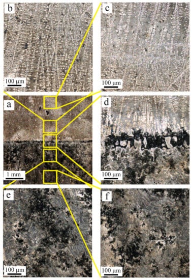
Figure 13.
(a) Corroded surface macrograph, (b,c) as-deposited AA4047 zones, (d) transition zone, (e) heat-affected 7075, (f) as-received AA7075-T42 [130].
In [132], the authors produced a titanium alloy with 52% aluminum by EBAM using pure Ti and Al wires. During the study, the authors showed that the actual Al content was lower than the calculated one due to the evaporation of elements during additive manufacturing. The microhardness of the resulting material varied widely from 240 MPa to 355 MPa. The authors also noted that this material was obtained for the first time by the EBAM method and did not contain structural defects that would lead to a deterioration of the mechanical properties. The results obtained testify to the possibility of obtaining products from alloys with controlled structures and a sufficiently accurate ratio of components by the method of electron beam double-wire printing.
The formation of composite materials based on the titanium alloy Ti-6Al-4V-0.07B and alloy Ti64 [165] allowed to obtain a layered material with a complex organized structure and high mechanical properties. The anisotropy of the properties of such composites predominantly consists of greater plasticity in the growing direction than in the printing direction. This was caused by the layered structure of the sample and the elimination of the formation of continuous interlayers of titanium boride along the boundaries of the initial β-phase grains. Obtaining a composite material based on titanium diboride and aluminum alloy [166] results in the distribution of strengthening phases mainly along the grain boundaries. Mechanical tests of the obtained composites show that the strength in the printing direction is slightly higher than in the growing direction of the sample. A prepared wire of the required composition was used to obtain this composite.
Obtaining the coating by the electron beam melting and surfacing of the titanium alloy TC4 with aluminum alloy ER5356 allows for obtaining composites hardened by TiAl3 particles, etc. [167]. This technique is an original variation of additive electron beam-assisted freeform fabrication (PEBF3) manufacturing. The obtained materials had improved tribological characteristics due to the formation of intermetallic phases, which shows the prospects of using this technique in practice.
In [168], using hybrid electron beam wire–powder manufacturing, they obtained composite materials based on AA5154 aluminum alloy with different concentrations (0.3, 0.6, 0.9, and 1.2 g/layer) of molybdenum powder, where part of the samples was formed by the deposition of aluminum alloy; then, the second part was printed by feeding molybdenum powder, resulting in its subsequent alloying with the aluminum wire fed into the melt pool. The authors found that increasing the concentration of molybdenum powder not only leads to a significant agglomeration of powder particles during melt crystallization (Figure 14) but also contributes to the formation of defects in the form of pores, cracks, and imperfections. Thus, values of microhardness for all samples change in a range from ~500 MPa to ~800 MPa, and the greatest values of microhardness for concentrations 0.3, 0.6, 0.9, and 1.2 g/layer make 2300, 2600, 11.500, and 9000 MPa, respectively, and correspond to the introduction of an indenter in the particles of the molybdenum and intermetallic phases Al12Mo, Al5Mo, Al8Mo3, and Al18Mg3Mo2, formed as a result of powder agglomeration and its alloying with an aluminum wire. In spite of the heterogeneity of the structure, the wear resistance of the material after the introduction of molybdenum powder considerably increases (practically up to two times) due to formations on the friction surface of molybdenum oxides Mo8O23 and aluminum molybdates Al2(MoO4)3. The received result testifies to the limited possibility of obtaining composite materials on the basis of components with significant differences in density and melting temperature. For the practical application of such materials, it is necessary to apply additional controlling influences in the printing process.
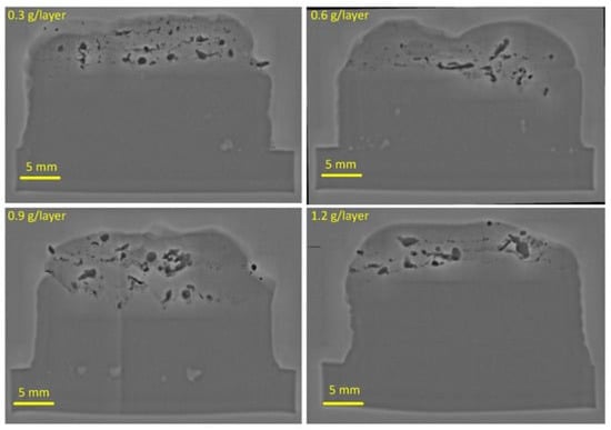
Figure 14.
X-ray images of molybdenum powder distribution in the surface layer of AA5056 aluminum alloy [168].
7.4. Bimetallic Products on “Steel–Nickel Alloy” and “Copper Alloy–Nickel Alloy” Systems
The high efficiency in obtaining graded samples based on steel and copper served in further research as a starting point for the production of more complex types of transitional bimetallic items based on nickel alloys and steels or nickel alloys and copper alloys. Elements on the basis of nickel alloys and austenitic steels have prospects for use in those areas where it is important, in addition to the heat resistance of the material, to maintain high anticorrosion properties. Bimetals based on heat-resistant bronzes and nickel alloys have potential applications for obtaining monolithic nozzles for rocket engines.
In [61], bimetallic transition elements based on steel and nickel alloy with a smooth gradient transition from one component to another were obtained. The resulting product contained four characteristic regions varying in height (Figure 15): austenitic steel; austenitic steel with NiCr; NiCr with austenitic steel; and NiCr. The stainless steel region is represented by the typical γ-austenite/δ-ferrite dendritic structure. As the NiCr region passes to the NiCr region, the δ-ferrite disappears, and pure γ-austenite is formed. This area contained large elongated grains with cellular dendrites inside. Regarding microhardness, the presence of two maxima in the area of austenitic steel and in the transition area was established, which corresponds to stable austenite; however, in the area of pure NiCr, the microhardness was the lowest. The obtained results indicate a high degree of applicability of the technology to obtain products with defect-free structures and the smoothest transition between components. This is caused by the wide possibilities regarding the regulation of the relative intensity of feeding of two filaments and the smooth change in a gradient zone. The wire-feed electron beam additive technology is one of the most acceptable at present for obtaining products of this type.
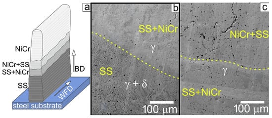
Figure 15.
Schematic representation illustrating the appearance of a product with gradient composition obtained by EBAM technology (a), the structure of the boundary between the steel and the transition zone (b) and between the steel-enriched and nickel-alloyed regions in the transition zone (c) [61].
Studies to obtain bimetallic-graded products based on heat-resistant bronze and heat-resistant nickel superalloys have been performed in [139,169]. Obtaining transition elements by printing nickel alloy over bronze and bronze over nickel alloy [169] allowed the authors to reveal the main regularities of the structures’ organizations at different orders of components printing. It was found that when printing CuCr1 bronze over Udimet500 nickel alloy, a more extended gradient zone is formed than when printing in reverse order. The transition zone is divided into a zone characterized by the coarse mechanical mixing of the components, a zone with a finely dispersed distribution of particles of the second component in the first component, and a zone of diffusion mixing. The mechanical properties of samples after printing are at a sufficiently high level. There is no unstrengthening of the gradient zone, and fracture during tensile testing across the structural gradient zone occurs in the least strong material—heat-resistant bronze.
Obtaining products from the nickel superalloy Udimet500 and the heat-resistant bronze CuCr1 in the form of double-row walls showed that the structure formation is significantly influenced by the printing strategy [139]. In this work, bimetallic elements (Figure 16a) were obtained by alternately printing two walls (Figure 16b) and by depositing one-part nickel alloy and one-part heat-resistant bronze on each layer (Figure 16c). Studies of the structure showed that the first type of the samples is characterized by a low mutual diffusion of components; however, due to the presence of irregularities on the first of the printed “walls”, some pores are rapidly cooled. Additionally, the mechanical properties of the material in those areas where there is a thin diffusion boundary are at a fairly high level. Such an interface is optimal in terms of ensuring the high strength of the nickel alloy and the thermal conductivity of the bronze. No pores are formed in the samples of the second type. However, the gradient zone is a rather wide layer characterized by the mechanical- and diffusion-mixing of components. This is due to the mixing of components on each layer because of the surface tension of the applied material, and with the application of each successive layer, the surface tension-tightened metal melts with the previous and subsequent layer. Thus, in terms of optimal interface thickness, the first option is the best, and for obtaining a defect-free structure, the second option is the best.
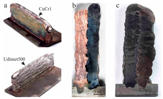
Figure 16.
(a) Appearance and (b) macrostructure of samples obtained by alternating printing of two separate “walls” and (c) by alternating printing with changing through each layer of printed material [139].
8. Modification of Structure and Hardening of Additive-Formed Materials by Friction Stirring Treatment
Friction stir processing (FSP) is a widely known method for processing various metals and alloys, including for obtaining composite materials [170,171]. Complexly organized metal flow along the tool contour [172], as well as the plastic deformation, fragmentation, and formation of an ultrafine structure allows for obtaining parts with improved mechanical properties or performance characteristics, especially when obtaining composites [173]. The strengthening of various products obtained by additive methods has a rather positive effect on the mechanical and tribological properties of the obtained products [174]. For this reason, the friction stir processing of materials obtained by electron beam additive manufacturing is relevant.
The use of friction stir processing for additively obtained aluminum alloy products is currently being utilized [29], including in combination with the layer-by-layer printing of samples [175]. The results of these works show that friction stirring treatment is effective for hardening additively produced materials. The strength, ductility, and fatigue-life of the samples are increased, while the anisotropy of the structure and its related properties are reduced. As applied to additive electron beam 3D printing, there are rather few works on post-processing using the FSP method. As a whole, few works on obtaining aluminum alloys by this method stand out.
In [176,177], aspects of the hardening of AA5056 and 04130 alloys produced by wire-feed electron beam additive manufacturing were considered. The ultimate strength of AA5056 alloy samples after FSP can reach 329 MPa, especially after up to four tool passes along the processing line. Such strength characteristics are typical for the sheet-rolled products of this alloy and significantly exceed the properties of initially printed samples (176–215 MPa). This is due to the structural changes in the samples (Figure 17) associated with grain size refinements from 1.6 to 2.5 µm, as well as the homogenization of the material at the macro level with the removal of pores and discontinuities. Similar structural changes occur in alloy 04130. The grain size decreases to 1.8–2.6 µm. The ultimate strength of the samples increases to a maximum of 217 MPa compared with the initial value of 176–180 MPa.
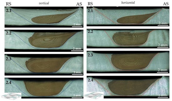
Figure 17.
Macrostructure of samples made by electron beam additive technology from AA5056 alloy after FSP in vertical and horizontal direction by modes 2.1–2.4. RS—retreating side, AS—advancing side, blue and red dashed lines indicate the stir zone boundaries [177].
The friction stir processing of titanium alloys [178,179] is also the main purpose of modifying the structure and hardening various parts. It is especially pronounced in the processing of products that are in the initially unstrengthened state. The processing of products made of titanium alloy Ti-6Al-4V obtained by wire-feed electron beam additive manufacturing revealed that the strength of the samples can significantly increase in comparison with the initial state [48,50]. The strength properties of the material significantly depend on the process parameters. Increasing the clamping force leads to a decrease in the strength properties. The strength of the material increases compared with the initial printed state up to values up to 64%, which exceeds the strength of the corresponding rolled sheet.
Obtaining materials with a combination of additive manufacturing methods and friction stir processing, although it has quite clear perspectives, but studied only a small number of works [180]. Only a small number of works on the modification of composites has been revealed with respect to the processing of products obtained by wire-feed electron beam manufacturing. Moreover, the heterogeneous distribution of strengthening phases in composites obtained by this method requires additional treatments, otherwise a number of materials, for example, based on components with sharply different density and melting temperature, cannot be used in practice. In addition, the works carried out on composite materials obtained by other methods proved to be sufficiently effective for this problem.
In [135,181], friction stir processing was first applied to improve the microstructure, microhardness, and tribological properties of Cu-Fe bimetal, which was previously obtained by the authors using the EBAM method by forming one half of the samples from stainless steel and the other half from copper. After processing the microhardness of copper, the zone from ~1.3 GPa to ~1.9 GPa considerably increases, while microhardness of steel increases from ~2 GPa to ~2.7 GPa, which is caused by a reduction in the sizes of structural elements. The tribological tests carried out by the authors have shown that the treated FSP specimens had a friction coefficient of 0.57 in comparison with the friction coefficient of untreated specimens (0.76). There was also a significant reduction in dry friction wear. The results of the work showed the high efficiency of the treatment to control the structure of the composites obtained by wire-feed electron beam additive manufacturing.
9. Conclusions
The review of literature sources in the field of wire additive electron beam technology for metal and alloy products shows that despite the presence of much more groundwork in other areas (DED, LD, WAAM), the considered technology has relevance in various applications. The application of electron beam technology allows to produce articles from titanium, aluminum, nickel, copper alloys, steels, and composite materials on different bases. Extensive opportunities are offered by the development of various methods of feeding the material into the melt bath. Samples are printed by feeding a wire filament into the printing zone. The electron beam fed into the printing zone forms a sweep, mainly in the form of an ellipse, due to which it melts the substrate and the wire, layer-by-layer depositing it to the surface. As a result, each layer partially melts the previous layer. Composites or transitional bimetallic components can be produced by the controlled feeding of two wires into the melt bath. Additionally, combined wire and powder feeding into the melt bath is possible. For printing samples of metals or alloys from which no wire is produced, special types of feeders based on the introduction of discrete bars of material loaded into a pushdown device into the printing area are possible.
The main characteristic features of the structure and properties of monometallic material samples obtained by electron beam additive manufacturing are elongated grains in the direction of heat removal, which are characterized by high plasticity and low strength. The anisotropy of the properties of the obtained materials mainly consists of higher strength values of the samples in the printing direction compared with the growing direction.
In general, a steady-state thermal process gives WEBAM the largest printed structure compared with other technologies, such as SLM, SLS, and DED, which use powders as starting materials. In combination with a small melt pool and high scanning speed [182], this results in the highest cooling rates and the smallest grain size. Of course, this also affects the properties of the resulting products. However, different processes have different application possibilities. Powder technology is excellent for the rapid prototyping of products and the manufacture of products smaller than what can be achieved with wire technology, such as WAAM and WEBAM. WAAM, on the other hand, is used for weldable materials, due to the technological features and the protection of the melt pool only. WEBAM has been shown in the survey to work with all materials, as the protection against oxidation is ensured by a vacuum chamber. Furthermore, ways of using starting materials in the form of bars have been developed. The use of bars as a raw material provides a wider range of applications for materials that are difficult to produce in the form of wires. Therefore, the efficiency of the WEBAM technology is higher than that of the previously listed technologies.
Regarding obtaining high-strength structures, this circumstance is a significant disadvantage. However, in the case of products with high heat-removal rates due to the directional structure, this situation is, on the contrary, a positive factor. Grain reduction in electron beam wire printing can be facilitated by controlling the heat input into the material or by heat removal, as well as by the use of additional influences. As can be seen, the different parameters of EBAM lead to the formation of grains of different sizes [183]. The heat input is changed by controlling the parameters of the electron beam, as well as the heat output by the intensity of table cooling. Without changing the chemical composition of the samples, grain refinement can be achieved by adding ultrasonic influences to the printing zone when obtaining products, as well as by conducting post-processing. Friction stir processing can be used as post-processing, which makes it possible to increase the initial low-strength properties to the rolled-sheet properties of the corresponding alloy, or even above them. Grain reduction is also possible through inoculating particles or metal powders into the printing zone for the in situ formation of intermetallic phases that inhibit grain growth. Control of the thermal gradient in the sample when printing nickel superalloys allows, on the contrary, to increase the size of the formed dendritic grains and to maximize the phenomenon of the directional crystallization of the material in the printing zone. Additional elements, such as a heated print table, can be used for this purpose.
Obtaining composite materials with a metal matrix allows the production of parts with increased strength or performance characteristics. It is also possible to create products with compositions and structures not achievable by traditional methods. The formation of composite materials is also affected by the tendency to form large grains that are elongated in the direction of heat dissipation. The main problems in obtaining products from different metals and alloys are the significant differences in the density and melting temperature of material, as well as the irregularity of the introduction of filament or powder into the melt bath. The obtained composites are distinguished by increased mechanical, tribological properties, etc. The use of surface alloying or the hardening of materials in printing makes it possible to save expensive materials when printing the whole product. Obtaining a gradient transition from the surface—to the main volume of the material—allows increasing the connection of the surface layer with the underlying layers.
Electron beam additive manufacturing also makes it possible to control the structure of products directly during printing and to feed different materials only in those areas of the product where they are required in principle. Various bimetallic transition elements based on different metals and alloys are successfully formed in this way. In the future, various bushings, adapters, rocket engine nozzles, containers for chemical equipment with high heat resistance or a heat sink, etc., can be produced by this method. Another promising area for the development of this technology could be the production of various homogeneous alloys, such as different alloys of titanium, aluminum, copper, or steels. This contributes to saving on alloying elements and the possibility of increasing corrosion resistance in addition to strength.
Most of the modern alloys used have their own technological characteristics that complicate the EBAM process. Copper and copper-based alloys have high thermal conductivity, which quickly removes heat from the melt bath, preventing it from reaching the required temperature. Copper alloys also tend to flow. Heat-resistant alloys based on nickel, cobalt, and iron are complex alloys, leading to the vaporization of fusible elements (e.g., aluminum); therefore, it is necessary to adjust the composition of the raw materials or look for other ways to achieve the required chemical composition. The disadvantage of printing with steel wire is the inevitable formation of directional structures, resulting in the anisotropy of the material’s properties. Additionally, the electron beam when acting on the steel comes under the influence of its magnetic field, which changes the preset shape of the beam sweep and leads to its deflection. Due to the problems described above, the most technologically advanced materials in terms of the EBAM process are titanium and its alloys. Although these materials are also prone to the formation of elongated columnar grains, much work is currently being conducted to solve this problem.
Thus, wire-feed electron beam additive manufacturing is a rapidly developing area of obtaining products from metals and alloys with monometallic structures, as well as composite materials and functionally graded products of various types. Compared with the other technologies involved in 3D wire-feed printing, it has significant advantages due to the implementation of printing in a vacuum, the possibility of implementing directional solidification, the fine control of the structure, and the properties of the finished products. For this reason, it is competitive, even in comparison with the currently widespread technologies of high-performance additive manufacturing.
In our point of view, the prospects for the development of WEBAM technology have several directions. First of all, it is necessary to create a set of studies to ensure the selection of optimal printing parameters for producing parts from metal alloys of different compositions and applications. The optimization of the WEBAM process will provide opportunities for the standardization of the produced materials for application in the aerospace industry, for aircraft construction, and most other important industries. Secondly, using WEBAM to modify the structures and properties of the produced materials. The modification includes methods such as addition of powders by printing to increase the number of crystallization nuclei or to increase strength/tribological characteristics; in situ vibration treatments in the frequency range from 100 Hz to 40 kHz (the most frequently used frequency ~20 kHz), which should also cause a refinement of the grain structure and change the rate of diffusion processes in multi-component materials; and post-processing, which can be of a different nature entirely, from heat treatment to thermomechanical impact. All of the above-mentioned methods for controlling the structures and properties will determine the further development of the WEBAM technology, as well as numerous other additive technologies.
Author Contributions
Conceptualization. A.C., V.R., and E.K.; writing—original draft preparation. K.O., K.K., A.C., D.G., T.K., A.V., A.Z., V.U., A.P., A.N., and A.D.; writing—review and editing. A.C. and A.D.; supervision. E.K.; project administration. V.R. All authors have read and agreed to the published version of the manuscript.
Funding
This research was funded by the Russian Federation Government under research assignment for ISPMS SB RAS. Project No. FWRW-2022-0004.
Institutional Review Board Statement
Not applicable.
Informed Consent Statement
Not applicable.
Data Availability Statement
Data sharing is not applicable to this article.
Acknowledgments
The work is partially supported the grant of the President of the Russian Federation for the state support of leading scientific schools NSh-1174.2022.4. The investigations have been carried out using the equipment of the Share Use Centre “Nanotech” of the ISPMS SB RAS.
Conflicts of Interest
The authors declare no conflict of interest.
References
- Kodama, H. Automatic Method for Fabricating a Three-dimensional Plastic Model with Photo-hardening Polymer. Rev. Sci. Instrum. 1981, 52, 1770–1773. [Google Scholar] [CrossRef]
- Melchels, F.P.W. Celebrating Three Decades of Stereolithography. Virtual Phys. Prototyp. 2012, 7, 173–175. [Google Scholar] [CrossRef]
- Olakanmi, E.O.; Cochrane, R.F.; Dalgarno, K.W. A Review on Selective Laser Sintering/Melting (SLS/SLM) of Aluminium Alloy Powders: Processing, Microstructure, and Properties. Prog. Mater. Sci. 2015, 74, 401–477. [Google Scholar] [CrossRef]
- Sefene, E.M. State-of-the-art of selective laser melting process: A comprehensive review. J. Manuf. Syst. 2022, 63, 250–274. [Google Scholar] [CrossRef]
- Lekurwale, S.; Karanwad, T.; Banerjee, S. Selective laser sintering (SLS) of 3D printlets using a 3D printer comprised of IR/red-diode laser. Ann. 3D Print. Med. 2022, 6, 100054. [Google Scholar] [CrossRef]
- Lulu-Bitton, N.; Sabatani, E.; Rosen, B.A.; Kostirya, N.; Agronov, G.; Tiferet, E.; Eliaz, N.; Navi, N.U. Mechanical behavior of electrochemically hydrogenated electron beam melting (EBM) and wrought Ti–6Al–4V using small punch test. Int. J. Hydrog. Energy 2022, 47, 6388–6403. [Google Scholar] [CrossRef]
- Onuike, B.; Bandyopadhyay, A. Bond strength measurement for additively manufactured Inconel 718- GRCop84 copper alloy bimetallic joints. Addit. Manuf. 2019, 27, 576–585. [Google Scholar] [CrossRef]
- Bouaziz, M.A.; Djouda, J.M.; Chemkhi, M.; Rambaudon, M.; Kauffmann, J.; Hild, F. Heat treatment effect on 17-4PH stainless steel manufactured by Atomic Diffusion Additive Manufacturing (ADAM). Procedia CIRP 2021, 104, 935–938. [Google Scholar] [CrossRef]
- Papyrin, A.; Kosarev, V.; Klinkov, S.; Alkhimov, A.; Fomin, V.M. Cold Spray Technology; Elsevier: Amsterdam, The Netherlands, 2007; pp. 1–32. [Google Scholar] [CrossRef]
- Singh, R.; Kondás, J.; Bauer, C.; Cizek, J.; Medricky, J.; Csaki, S.; Čupera, J.; Procházka, R.; Melzer, D.; Konopík, P. Bulk-like ductility of cold spray additively manufactured copper in the as-sprayed state. Addit. Manuf. Lett. 2022, 3, 100052. [Google Scholar] [CrossRef]
- Liu, J.; Xu, Y.; Ge, Y.; Hou, Z.; Chen, S. Wire and Arc Additive Manufacturing of Metal Components: A Review of Recent Research Developments. Int. J. Adv. Manuf. Technol. 2020, 111, 149–198. [Google Scholar] [CrossRef]
- Recent Studies of Laser Metal 3D Deposition with Wire Feeding. J. Weld. Join. 2016, 34, 35–40. [CrossRef]
- Tarasov, S.Y.; Filippov, A.V.; Shamarin, N.N.; Fortuna, S.V.; Maier, G.G.; Kolubaev, E.A. Microstructural Evolution and Chemical Corrosion of Electron Beam Wire-Feed Additively Manufactured AISI 304 Stainless Steel. J. Alloys Compd. 2019, 803, 364–370. [Google Scholar] [CrossRef]
- Evans, S.I.; Wang, J.; Qin, J.; He, Y.; Shepherd, P.; Ding, J. A review of WAAM for steel construction–Manufacturing, material and geometric properties, design, and future directions. Structures 2022, 44, 1506–1522. [Google Scholar] [CrossRef]
- Ding, D.; Pan, Z.; Cuiuri, D.; Li, H. Wire-Feed Additive Manufacturing of Metal Components: Technologies, Developments and Future Interests. Int. J. Adv. Manuf. Technol. 2015, 81, 465–481. [Google Scholar] [CrossRef]
- Negi, S.; Nambolan, A.A.; Kapil, S.; Joshi, P.S.R.M.; Karunakaran, K.P.; Bhargava, P. Review on Electron Beam Based Additive Manufacturing. Rapid Prototyp. J. 2020, 26, 485–498. [Google Scholar] [CrossRef]
- Węglowski, M.S.; Błacha, S.; Pilarczyk, J.; Dutkiewicz, J.; Rogal, Ł. Electron Beam Additive Manufacturing with Wire–Analysis of the Process. AIP Conf. Proc. 2018, 1960, 140015. [Google Scholar] [CrossRef]
- Kolubaev, E.A.; Rubtsov, V.E.; Chumaevsky, A.V.; Astafurova, E.G. Micro-, Meso- and Macrostructural Design of Bulk Metallic and Polymetallic Materials by Wire-Feed Electron-Beam Additive Manufacturing. Phys. Mesomech. 2022, 25, 479–491. [Google Scholar] [CrossRef]
- Tshephe, T.S.; Akinwamide, S.O.; Olevsky, E.; Olubambi, P.A. Additive manufacturing of titanium-based alloys- A review of methods, properties, challenges, and prospects. Heliyon 2022, 8, e09041. [Google Scholar] [CrossRef]
- Shahwaz, M.; Nath, P.; Sen, I. A critical review on the microstructure and mechanical properties correlation of additively manufactured nickel-based superalloys. J. Alloys Compd. 2022, 907, 164530. [Google Scholar] [CrossRef]
- Guo, L.; Zhang, L.; Andersson, J.; Ojo, O. Additive manufacturing of 18% nickel maraging steels: Defect, structure and mechanical properties: A review. J. Mater. Sci. Technol. 2022, 120, 227–252. [Google Scholar] [CrossRef]
- Zhang, D.; Liu, A.; Yin, B.; Wen, P. Additive manufacturing of duplex stainless steels—A critical review. J. Manuf. Process. 2022, 73, 496–517. [Google Scholar] [CrossRef]
- Kong, D.; Dong, C.; Wei, S.; Ni, X.; Zhang, L.; Li, R.; Wang, L.; Man, C.; Li, X. About metastable cellular structure in additively manufactured austenitic stainless steels. Addit. Manuf. 2021, 38, 101804. [Google Scholar] [CrossRef]
- Roccetti Campagnoli, M.; Galati, M.; Saboori, A. On the processability of copper components via powder-based additive manufacturing processes: Potentials, challenges and feasible solutions. J. Manuf. Process. 2021, 72, 320–337. [Google Scholar] [CrossRef]
- Altıparmak, S.C.; Yardley, V.A.; Shi, Z.; Lin, J. Challenges in additive manufacturing of high-strength aluminium alloys and current developments in hybrid additive manufacturing. Int. J. Light. Mater. Manuf. 2021, 4, 246–261. [Google Scholar] [CrossRef]
- Kumar Sinha, A.; Pramanik, S.; Yagati, K.P. Research progress in arc based additive manufacturing of aluminium alloys—A review. Measurement 2022, 200, 111672. [Google Scholar] [CrossRef]
- Bandyopadhyay, A.; Heer, B. Additive manufacturing of multi-material structures. Mater. Sci. Eng. R Rep. 2018, 129, 1–16. [Google Scholar] [CrossRef]
- Shakil, S.I.; Smith, N.R.; Yoder, S.P.; Ross, B.E.; Alvarado, D.J.; Hadadzadeh, A.; Haghshenas, M. Post fabrication thermomechanical processing of additive manufactured metals: A review. J. Manuf. Process. 2022, 73, 757–790. [Google Scholar] [CrossRef]
- He, P.; Bai, X.; Zhang, H. Microstructure refinement and mechanical properties enhancement of wire and arc additively manufactured 6061 aluminum alloy using friction stir processing post-treatment. Mater. Lett. 2023, 330, 133365. [Google Scholar] [CrossRef]
- Sibum, H.; Güther, V.; Roidl, O.; Habashi, F.; Wolf, H.; Siemers, C. Titanium, Titanium Alloys and Titanium Compounds. In Ullmann’s Encyclopedia of Industrial Chemistry; Wiley: Weinheim, Germany, 2017; pp. 1–35. [Google Scholar]
- Boyer, R.R. An Overview on the Use of Titanium in the Aerospace Industry. Mater. Sci. Eng. A 1996, 213, 103–114. [Google Scholar] [CrossRef]
- Boyer, R.R. Attributes, Characteristics, and Applications of Titanium and Its Alloys. JOM 2010, 62, 21–24. [Google Scholar] [CrossRef]
- FUJII, H.; TAKAHASHI, K.; YAMASHITA, Y. Application of Titanium and Its Alloys for Automobile Parts. Nippon Steel Tech. Rep. 2003, 88, 70–75. [Google Scholar]
- Lee, H.S.; Yoon, J.H.; Yoo, J.T. Manufacturing Titanium and Al-Li Alloy Cryogenic Tanks. Key Eng. Mater. 2020, 837, 64–68. [Google Scholar] [CrossRef]
- Cotton, J.D.; Briggs, R.D.; Boyer, R.R.; Tamirisakandala, S.; Russo, P.; Shchetnikov, N.; Fanning, J.C. State of the Art in Beta Titanium Alloys for Airframe Applications. JOM 2015, 67, 1281–1303. [Google Scholar] [CrossRef]
- Singh, P.; Pungotra, H.; Kalsi, N.S. On the Characteristics of Titanium Alloys for the Aircraft Applications. Mater. Today Proc. 2017, 4, 8971–8982. [Google Scholar] [CrossRef]
- Peters, M.; Kumpfert, J.; Ward, C.H.; Leyens, C. Titanium Alloys for Aerospace Applications. Adv. Eng. Mater. 2003, 5, 419–427. [Google Scholar] [CrossRef]
- Veiga, C.; Davim, J.; Loureiro, A. Review on Machinability of Titanium Alloys: The Process Perspective. Rev. Adv. Mater. Sci. 2013, 34, 148–164. [Google Scholar]
- Pramanik, A. Problems and Solutions in Machining of Titanium Alloys. Int. J. Adv. Manuf. Technol. 2014, 70, 919–928. [Google Scholar] [CrossRef]
- Taminger, K.M.; Hafley, R.A. Electron Beam Freeform Fabrication for Cost Effective Near-Net Shape Manufacturing. NATO/RTO AVT 2006, 139, 11–16. [Google Scholar]
- Wanjara, P.; Watanabe, K.; de Formanoir, C.; Yang, Q.; Bescond, C.; Godet, S.; Brochu, M.; Nezaki, K.; Gholipour, J.; Patnaik, P. Titanium Alloy Repair with Wire-Feed Electron Beam Additive Manufacturing Technology. Adv. Mater. Sci. Eng. 2019, 2019, 3979471. [Google Scholar] [CrossRef]
- Electron Beam Additive Manufacturing (EBAM®). Available online: https://www.sciaky.com/additive-manufacturing/electron-beam-additive-manufacturing-technology (accessed on 27 December 2022).
- Pixner, F.; Warchomicka, F.; Peter, P.; Steuwer, A.; Colliander, M.H.; Pederson, R.; Enzinger, N. Wire-Based Additive Manufacturing of Ti-6Al-4V Using Electron Beam Technique. Materials 2020, 13, 3310. [Google Scholar] [CrossRef]
- Zhang, G.; Xiong, H.; Yu, H.; Qin, R.; Liu, W.; Yuan, H. Microstructure Evolution and Mechanical Properties of Wire-Feed Electron Beam Additive Manufactured Ti-5Al-2Sn-2Zr-4Mo-4Cr Alloy with Different Subtransus Heat Treatments. Mater. Des. 2020, 195, 109063. [Google Scholar] [CrossRef]
- Kalashnikov, K.N.; Chumaevskii, A.V.; Kalashnikova, T.A.; Kolubaev, E.A. A Substrate Material and Thickness Influence on the 3D-Printing of Ti–6Al–4V Components via Wire-Feed Electron Beam Additive Manufacturing. J. Mater. Res. Technol. 2022, 16, 840–852. [Google Scholar] [CrossRef]
- Panin, A.; Martynov, S.; Kazachenok, M.; Kazantseva, L.; Bakulin, A.; Kulkova, S.; Perevalova, O.; Sklyarova, E. Effects of Water Cooling on the Microstructure of Electron Beam Additive-Manufactured Ti-6Al-4V. Metals 2021, 11, 1742. [Google Scholar] [CrossRef]
- Kalashnikov, K.N.; Rubtsov, V.E.; Savchenko, N.L.; Kalashnikova, T.A.; Osipovich, K.S.; Eliseev, A.A.; Chumaevskii, A.V. The Effect of Wire Feed Geometry on Electron Beam Freeform 3D Printing of Complex-Shaped Samples from Ti-6Al-4V Alloy. Int. J. Adv. Manuf. Technol. 2019, 105, 3147–3156. [Google Scholar] [CrossRef]
- Kalashnikov, K.; Chumaevskii, A.; Kalashnikova, T.; Cheremnov, A.; Moskvichev, E.; Amirov, A.; Krasnoveikin, V.; Kolubaev, E. Friction Stir Processing of Additively Manufactured Ti-6Al-4V Alloy: Structure Modification and Mechanical Properties. Metals 2021, 12, 55. [Google Scholar] [CrossRef]
- Carroll, B.E.; Palmer, T.A.; Beese, A.M. Anisotropic Tensile Behavior of Ti–6Al–4V Components Fabricated with Directed Energy Deposition Additive Manufacturing. Acta Mater. 2015, 87, 309–320. [Google Scholar] [CrossRef]
- Kalashnikova, T.; Cheremnov, A.; Eliseev, A.; Gurianov, D.; Knyazhev, E.; Moskvichev, E.; Beloborodov, V.; Chumaevskii, A.; Zykova, A.; Kalashnikov, K. Structural Changes in Block-Shaped WEBAM’ed Ti6Al4V Samples after Friction Stir Processing. Lubricants 2022, 10, 349. [Google Scholar] [CrossRef]
- Matz, J.E.; Eagar, T.W. Carbide formation in alloy 718 during electron-beam solid freeform fabrication. Met. Mater. Trans. A 2020, 33, 2559–2567. [Google Scholar] [CrossRef]
- Waters, B.R. Mechanical Properties of Inconel 718 Processed Using Electron Beam Free Form Fabrication (EBAM). Master’s Thesis, Brigham Young University, Provo, UT, USA, 2018. [Google Scholar]
- Tayon, W.A.; Shenoy, R.N.; Redding, M.R.; Keith Bird, R.; Hafley, R.A. Correlation Between Microstructure and Mechanical Properties in an Inconel 718 Deposit Produced Via Electron Beam Freeform Fabrication. Manuf. Sci. Eng. 2014, 136, 061005. [Google Scholar] [CrossRef]
- Tayon, W.; Shenoy, R.; Bird, T.; Hafley, R.; Redding, M. Texture-induced anisotropy in an inconel 718 alloy deposited using electron beam freeform fabrication. In Proceedings of the International Conference on Texture of Materials, Dresden, Germany, 24–29 August 2014. [Google Scholar]
- Bird, R.K.; Atherton, T.S. Effect of Orientation on Tensile Properties of Inconel 718 Block Fabricated with Electron Beam Freeform Fabrication (EBAM). Technical Memorandum. NASA/TM-2010-216719. In Proceedings of the Langley Research Center, Hampton, VA, USA, 13–15 April 2010. [Google Scholar]
- Bird, R.K.; Hibberd, J. Tensile Properties and Microstructure of Inconel 718 Fabricated with Electron Beam Freeform Fabrication (EBAM); Technical Memorandum. NASA/TM-2009-215929; Langley Research Center: Hampton, VA, USA, 2009; pp. 1–19. [Google Scholar]
- Hales, S.J.; Domack, C.S.; Brown, T.; Karen, M. Electron Beam Freeform Fabrication of Dissimilar Materials: Cracking in Inconel 625 on GRCop-84; Technical Publication NASA-TP-2020-5005040; Langley Research Center: Hampton, VA, USA, 2020; pp. 1–83. [Google Scholar]
- Wahlmann, B.; Korner, C.; Nunn, M. Electron beam wire cladding of nickel alloys and stainless steel on a reactor pressure vessel steel. Mater. Sci. Eng. A 2021, 811, 141082. [Google Scholar] [CrossRef]
- Xu, D.; Wang, H.; Tao, X.; Yao, Z.; Zhang, S.; Oleksander, M. Investigation on Microstructure, Hardness and Wear Resistance of Electron Beam Wire-Feeding Deposited Inconel 718 Alloy Coatings. Met. Mater. Int. 2021, 27, 1263–1272. [Google Scholar] [CrossRef]
- Sun, W.; Xin, J.; Wang, S.; Chen, Y.; Huang, Y. Effect of deposited layer thickness on the microstructure and mechanical properties of IC10 single-crystal Ni3Al-based alloy electron beam welded joint. J. Mater. Res. Technol. 2021, 11, 1206–1219. [Google Scholar] [CrossRef]
- Moskvina, V.A.; Melnikov, E.V.; Panchenko, M.Y.; Maier, G.G.; Reunova, K.A.; Astafurov, S.V.; Kolubaev, E.A.; Astafurova, E.G. Stabilization of austenitic structure in transition zone of “austenitic stainless steel/NiCr alloy” joint fabricated by wire-feed electron beam melting. Mater. Lett. 2020, 277, 128321. [Google Scholar] [CrossRef]
- Small, K.A.; Taheri, M.L. Role of Processing in Microstructural Evolution in Inconel 625: A Comparison of Three Additive Manufacturing Techniques. Metall. Mater. Trans. A 2021, 52, 2811–2820. [Google Scholar] [CrossRef]
- Fortuna, S.V.; Gurianov, D.A.; Kalashnikov, K.N.; Chumaevskii, A.V.; Mironov, Y.P.; Kolubaev, E.A. Directional Solidification of a Nickel-Based Superalloy Product Structure Fabricated on Stainless Steel Substrate by Electron Beam Additive Manufacturing. Met. Mater. Trans. A 2021, 52, 857–870. [Google Scholar] [CrossRef]
- Fortuna, S.V.; Gurianov, D.A.; Kalashnikov, K.N. Directional solidification features of nickel-based superalloy in the electron beam additive manufacturing process. AIP Conf. Proc. 2019, 2167, 020107. [Google Scholar] [CrossRef]
- Safarzade, A.; Sharifitabar, M.; Afarani, M.S. Effects of heat treatment on microstructure and mechanical properties of Inconel 625 alloy fabricated by wire arc additive manufacturing process. Trans. Nonferrous Met. Soc. China 2020, 30, 3016–3030. [Google Scholar] [CrossRef]
- Asala, G.; Andersson, J.; Ojo, O.A. Improved dynamic impact behaviour of wire-arc additive manufactured ATI 718Plus®. Mater. Sci. Eng. A 2018, 738, 111–124. [Google Scholar] [CrossRef]
- Seow, C.E.; Zhang, J.; Coules, H.E. Effect of crack-like defects on the fracture behaviour of Wire + Arc Additively Manufactured nickel-base Alloy 718. Addit. Manuf. 2020, 36, 101578. [Google Scholar] [CrossRef]
- Baufeld, B. Mechanical Properties of INCONEL 718 Parts Manufactured by Shaped Metal Deposition (SMD). J. Mater. Eng. Perform. 2012, 21, 1416–1421. [Google Scholar] [CrossRef]
- Qiu, Z.; Wu, B.; Zhu, H.; Wang, Z.; Hellier, A.; Ma, Y.; Li, H.; Muransky, O.; Wexel, D. Microstructure and mechanical properties of wire arc additively manufactured Hastelloy C276 alloy. Mater. Des. 2020, 195, 109007. [Google Scholar] [CrossRef]
- Rodrigues, T.A.; Duarte, V.; Miranda, R.M.; Santos, T.G.; Oliveira, J.P. Current Status and Perspectives on Wire and Arc Additive Manufacturing (WAAM). Materials 2019, 12, 1121. [Google Scholar] [CrossRef] [PubMed]
- Cormier, D.; Harrysson, O.; West, H. Characterization of H13 steel produced via electron beam melting. Rapid Prototyp. J. 2004, 10, 35–41. [Google Scholar] [CrossRef]
- Gardner, L. Stability and design of stainless steel structures–Review and outlook. Thin Walled Struct. 2019, 141, 208–216. [Google Scholar] [CrossRef]
- Grigorescu, A.C.; Hilgendorff, P.M.; Zimmermann, M.; Fritzen, C.P.; Christ, H.J. Cyclic deformation behavior of austenitic Cr–Ni-steels in the VHCF regime: Part I–Experimental study. Int. J. Fatigue 2016, 93, 250–260. [Google Scholar] [CrossRef]
- Kalinin, G.; Barabash, V.; Cardella, A.; Dietz, J.; Ioki, K.; Matera, R.; Santoro, R.T.; Tivey, R. Assessment and selection of materials for ITER in-vessel components. J. Nucl. Mater. 2000, 283–287, 10–19. [Google Scholar] [CrossRef]
- Hsiao, C.N.; Chiou, C.S.; Yang, J.R. Aging reactions in a 17-4 PH stainless steel. Mater. Chem. Phys. 2002, 74, 134–142. [Google Scholar] [CrossRef]
- Fayazfar, H.; Salarian, M.; Rogalsky, A.; Sarker, D.; Russo, P.; Paserin, V.; Toyserkani, E. A critical review of powder-based additive manufacturing of ferrous alloys: Process parameters, microstructure and mechanical properties. Mater. Des. 2018, 144, 98–128. [Google Scholar] [CrossRef]
- Kumar, S.; Pityana, S. Laser-Based Additive Manufacturing of Metals. Adv. Mater. Res. 2011, 227, 92–95. [Google Scholar] [CrossRef]
- Rannar, L.E.; Glad, A.; Gustafson, C.G. Efficient cooling with tool inserts manufactured by electron beam melting. Rapid Prototyp. J. 2007, 13, 128–135. [Google Scholar] [CrossRef]
- Bajaj, P.; Hariharan, A.; Kini, A.; Kürnsteiner, P.; Raabe, D.; Jägle, E.A. Steels in additive manufacturing: A review of their microstructure and properties. Mater. Sci. Eng. A 2020, 772, 138633. [Google Scholar] [CrossRef]
- Astafurov, S.; Astafurova, E. Phase Composition of Austenitic Stainless Steels in Additive Manufacturing: A Review. Metals 2021, 11, 1052. [Google Scholar] [CrossRef]
- Panchenko, M.Y.; Astafurova, E.G.; Moskvina, V.A.; Maier, G.G.; Astafurov, S.V.; Melnikov, E.V.; Reunova, K.A.; Rubtsov, V.E.; Kolubaev, E.A. The effect of niobium on microstructure and mechanical properties of austenitic crni steel produced by wire-feed electron beam additive manufacturing. Nanosci. Technol. Int. J. 2020, 11, 109–118. [Google Scholar] [CrossRef]
- Astafurova, E.G.; Panchenko, M.Y.; Moskvina, V.A.; Maier, G.G.; Astafurov, S.V.; Melnikov, E.V.; Fortuna, A.S.; Reunova, K.A.; Rubtsov, V.E.; Kolubaev, E.A. Microstructure and grain growth inhomogeneity in austenitic steel produced by wire-feed electron beam melting: The effect of post-building solid-solution treatment. J. Mater. Sci. 2020, 55, 9211–9224. [Google Scholar] [CrossRef]
- Feng, Y.; Zhan, B.; He, J.; Wang, K. The double-wire feed and plasma arc additive manufacturing process for deposition in Cr-Ni stainless steel. J. Mater. Process. Technol. 2018, 259, 206–215. [Google Scholar] [CrossRef]
- Herzog, D.; Seyda, V.; Wycisk, E.; Emmelmann, C. Additive manufacturing of metals. Acta Mater. 2016, 117, 371–392. [Google Scholar] [CrossRef]
- Tarasov, S.Y.; Filippov, A.V.; Savchenko, N.L.; Fortuna, S.V.; Rubtsov, V.E.; Kolubaev, E.A.; Psakhie, S.G. Effect of heat input on phase content, crystalline lattice parameter, and residual strain in wire-feed electron beam additive manufactured 304 stainless steel. Int. J. Adv. Manuf. Technol. 2018, 99, 2353–2363. [Google Scholar] [CrossRef]
- Lin, X.; Yue, T.M. Phase formation and microstructure evolution in laser rapid forming of graded SS316L/Rene88DT alloy. Mater. Sci. Eng. A 2005, 402, 294–306. [Google Scholar] [CrossRef]
- Huang, Y.; Ansari, M.; Asgari, H.; Farshidianfar, M.H.; Sarker, D.; Khamesee, M.B.; Toyserkani, E. Rapid prediction of real-time thermal characteristics, solidification parameters and microstructure in laser directed energy deposition (powder-fed additive manufacturing). J. Mater. Process. Technol. 2019, 274, 116286. [Google Scholar] [CrossRef]
- Abd-Elghany, K.; Bourell, D.L. Property evaluation of 304L stainless steel fabricated by selective laser melting. Rapid Prototyp. J. 2012, 18, 420–428. [Google Scholar] [CrossRef]
- Niendorf, T.; Leuders, S.; Riemer, A.; Richard, H.A.; Tröster, T.; Schwarze, D. Highly anisotropic steel processed by selective laser melting. Metall. Mater. Trans. B Process Metall. Mater. Process. Sci. 2013, 44, 794–796. [Google Scholar] [CrossRef]
- Ma, M.; Wang, Z.; Wang, D.; Zeng, X. Control of shape and performance for direct laser fabrication of precision large-scale metal parts with 316L Stainless Steel. Opt. Laser Technol. 2013, 45, 209–216. [Google Scholar] [CrossRef]
- Luecke, W.E.; Slotwinski, J.A. Mechanical Properties of Austenitic Stainless Steel Made by Additive Manufacturing. J. Res. Natl. Inst. Stand. Technol. 2014, 119, 15. [Google Scholar] [CrossRef] [PubMed]
- DebRoy, T.; Wei, H.L.; Zuback, J.S.; Mukherjee, T.; Elmer, J.W.; Milewski, J.O.; Beese, A.M.; Wilson-Heid, A.; De, A.; Zhang, W. Additive manufacturing of metallic components—Process, structure and properties. Prog. Mater. Sci. 2018, 92, 112–224. [Google Scholar] [CrossRef]
- Wanjara, P.; Brochu, M.; Jahazi, M. Electron beam freeforming of stainless steel using solid wire feed. Mater. Des. 2007, 28, 2278–2286. [Google Scholar] [CrossRef]
- Nassour, A.; Bose, W.W.; Spinelli, D. Creep properties of austenitic stainless-steel weld metals. J. Mater. Eng. Perform. 2001, 10, 693–698. [Google Scholar] [CrossRef]
- Sun, G.F.; Yao, S.; Wang, Z.D.; Shen, X.T.; Yan, Y.; Zhou, R.; Ni, Z.H. Microstructure and mechanical properties of HSLA-100 steel repaired by laser metal deposition. Surf. Coat. Technol. 2018, 351, 198–211. [Google Scholar] [CrossRef]
- Abramov, O.V. High-Intensity Ultrasonics: Theory and Industrial Applications. High-Intensity Ultrason. 2019, 21, 1954. [Google Scholar] [CrossRef]
- Vorontsov, A.; Astafurov, S.; Melnikov, E.; Moskvina, V.; Kolubaev, E.; Astafurova, E. The microstructure, phase composition and tensile properties of austenitic stainless steel in a wire-feed electron beam melting combined with ultrasonic vibration. Mater. Sci. Eng. A 2021, 820, 141519. [Google Scholar] [CrossRef]
- Jadhav, S.D.; Dadbakhsh, S.; Goossens, L.; Kruth, J.-P.; Van Humbeeck, J.; Vanmeensel, K. Influence of selective laser melting process parameters on texture evolution in pure copper. J. Mater. Process. Technol. 2019, 270, 47–58. [Google Scholar] [CrossRef]
- Singer, F.; Deisenroth, D.C.; Hymas, D.M.; Ohadi, M.M. Additively manufactured copper components and composite structures for thermal management applications. In Proceedings of the 2017 16th IEEE Intersociety Conference on Thermal and Thermomechanical Phenomena in Electronic Systems, Orlando, FL, USA, 30 May–2 June 2017; pp. 174–183. [Google Scholar] [CrossRef]
- El-Wardany, T.I.; She, Y.; Jagdale, V.N.; Garofano, J.K.; Liou, J.J.; Schmidt, W.R. Challenges in Three-Dimensional Printing of High-Conductivity Copper. J. Electron. Packag. Trans. ASME 2018, 140, 39974. [Google Scholar] [CrossRef]
- Li, J.; Cai, Y.; Yan, F.; Wang, C.; Zhu, Z.; Hu, C. Porosity and liquation cracking of dissimilar Nd:YAG laser welding of SUS304 stainless steel to T2 copper. Opt. Laser Technol. 2020, 122, 105881. [Google Scholar] [CrossRef]
- Wolf, T.; Fu, Z.; Körner, C. Selective electron beam melting of an aluminum bronze: Microstructure and mechanical properties. Mater. Lett. 2019, 238, 241–244. [Google Scholar] [CrossRef]
- Osipovich, K.S.; Chumaevskii, A.V.; Eliseev, A.A.; Kalashnikov, K.N.; Kolubaev, E.A.; Rubtsov, V.E.; Astafurova, E.G. Peculiarities of Structure Formation in Copper/Steel Bimetal Fabricated by Electron-Beam Additive Technology. Russ. Phys. J. 2019, 62, 1867. [Google Scholar] [CrossRef]
- Moriya, S.; Inoue, T.; Sasaki, M.; Nakamoto, T.; Kimura, T.; Nomura, N.; Kikuchi, K.; Kawasaki, A.; Kato, T.; Masuda, I. Feasibility Study on Additive Manufacturing of Liquid Rocket Combustion Chamber. Trans. JAPAN Soc. Aeronaut. Sp. Sci. Aerosp. Technol. JAPAN 2018, 16, 261–266. [Google Scholar] [CrossRef]
- Ledford, C.; Rock, C.; Carriere, P.; Frigola, P.; Gamzina, D.; Horn, T. Characteristics and Processing of Hydrogen-Treated Copper Powders for EB-PBF Additive Manufacturing. Appl. Sci. 2019, 9, 3993. [Google Scholar] [CrossRef]
- King, W.E.; Anderson, A.T.; Ferencz, R.M.; Hodge, N.E.; Kamath, C.; Khairallah, S.A.; Rubenchik, A.M. Laser powder bed fusion additive manufacturing of metals; physics, computational, and materials challenges. Appl. Phys. Rev. 2015, 2, 041304. [Google Scholar] [CrossRef]
- Dehoff, R.R.; Kirka, M.M.; Sames, W.J.; Bilheux, H.; Tremsin, A.S.; Lowe, L.E.; Babu, S.S. Site specific control of crystallographic grain orientation through electron beam additive manufacturing. Mater. Sci. Technol. 2014, 31, 931–938. [Google Scholar] [CrossRef]
- Chen, N.; Khan, H.A.; Wan, Z.; Lippert, J.; Sun, H.; Shang, S.L.; Liu, Z.K.; Li, J. Microstructural characteristics and crack formation in additively manufactured bimetal material of 316L stainless steel and Inconel 625. Addit. Manuf. 2020, 32, 101037. [Google Scholar] [CrossRef]
- Zhang, X.; Pan, T.; Chen, Y.; Li, L.; Zhang, Y.; Liou, F. Additive manufacturing of copper-stainless steel hybrid components using laser-aided directed energy deposition. J. Mater. Sci. Technol. 2021, 80, 100–116. [Google Scholar] [CrossRef]
- Osipovich, K.; Vorontsov, A.; Chumaevskii, A.; Moskvichev, E.; Zakharevich, I.; Dobrovolsky, A.; Sudarikov, A.; Zykova, A.; Rubtsov, V.; Kolubaev, E. Features of Microstructure and Texture Formation of Large-Sized Blocks of C11000 Copper Produced by Electron Beam Wire-Feed Additive Technology. Materials 2022, 15, 814. [Google Scholar] [CrossRef] [PubMed]
- Wang, C.; Li, Y.; Tian, W.; Hu, J.; Li, B.; Li, P.; Liao, W. Influence of Ultrasonic Impact Treatment and Working Current on Microstructure and Mechanical Properties of 2219 Aluminium Alloy Wire Arc Additive Manufacturing Parts. J. Mater. Res. Technol. 2022, 21, 781–797. [Google Scholar] [CrossRef]
- Zhou, Y.; Lin, X.; Kang, N.; Huang, W.; Wang, Z. Mechanical Properties and Precipitation Behavior of the Heat-Treated Wire + Arc Additively Manufactured 2219 Aluminum Alloy. Mater. Charact. 2021, 171, 110735. [Google Scholar] [CrossRef]
- Guo, N.; Wu, D.; Wang, G.; Cheng, Q.; Fu, Y.; Yu, M. Investigation on Underwater Wire-Feed Laser Deposition of 5052 Aluminum Alloy. J. Manuf. Process. 2022, 76, 687–694. [Google Scholar] [CrossRef]
- Brice, C.A.; Tayon, W.A.; Newman, J.A.; Kral, M.V.; Bishop, C.; Sokolova, A. Effect of Compositional Changes on Microstructure in Additively Manufactured Aluminum Alloy 2139. Mater. Charact. 2018, 143, 50–58. [Google Scholar] [CrossRef]
- Utyaganova, V.R.; Filippov, A.V.; Shamarin, N.N.; Vorontsov, A.V.; Savchenko, N.L.; Fortuna, S.V.; Gurianov, D.A.; Chumaevskii, A.V.; Rubtsov, V.E.; Tarasov, S.Y. Controlling the Porosity Using Exponential Decay Heat Input Regimes during Electron Beam Wire-Feed Additive Manufacturing of Al-Mg Alloy. Int. J. Adv. Manuf. Technol. 2020, 108, 2823–2838. [Google Scholar] [CrossRef]
- Knyazhev, E.O.; Panfilov, A.O.; Kalashnikova, T.A.; Kalashnikov, K.N.; Gusarova, A.V.; Chumaevskii, A.V. Structure Formation Features of Large Block-Shaped Samples from AA5356 Alloy at the Electron-Beam Wire-Feed Additive Manufacturing; AIP Publishing LLC: Melville, NY, USA, 2020; p. 020151. [Google Scholar]
- Chumaevskii, A.V.; Nikonov, S.Y.; Gusarova, A.V.; Knyazhev, E.O.; Panfilov, A.O.; Zykova, A.P.; Gurianov, D.A. Anisotropy of the Aluminum-Silicon and Aluminum-Magnesium Alloys Properties Produced by Wire-Feed Electron Beam Additive Manufacturing; AIP Publishing LLC: Melville, NY, USA, 2022; p. 020047. [Google Scholar]
- Feenstra, D.R.; Banerjee, R.; Fraser, H.L.; Huang, A.; Molotnikov, A.; Birbilis, N. Critical Review of the State of the Art in Multi-Material Fabrication via Directed Energy Deposition. Curr. Opin. Solid State Mater. Sci. 2021, 25, 100924. [Google Scholar] [CrossRef]
- Chandrasekaran, S.; Hari, S.; Amirthalingam, M. Wire Arc Additive Manufacturing of Functionally Graded Material for Marine Risers. Mater. Sci. Eng. A 2020, 792, 139530. [Google Scholar] [CrossRef]
- Wu, B.; Qiu, Z.; Pan, Z.; Carpenter, K.; Wang, T.; Ding, D.; Duin, S.V.; Li, H. Enhanced Interface Strength in Steel-Nickel Bimetallic Component Fabricated Using Wire Arc Additive Manufacturing with Interweaving Deposition Strategy. J. Mater. Sci. Technol. 2020, 52, 226–234. [Google Scholar] [CrossRef]
- Shen, C.; Liss, K.-D.; Reid, M.; Pan, Z.; Hua, X.; Li, F.; Mou, G.; Huang, Y.; Zhu, Y.; Li, H. Fabrication of FeNi Intermetallic Using the Wire-Arc Additive Manufacturing Process: A Feasibility and Neutron Diffraction Phase Characterization Study. J. Manuf. Process. 2020, 57, 691–699. [Google Scholar] [CrossRef]
- Shen, C.; Liss, K.-D.; Reid, M.; Pan, Z.; Hua, X.; Li, F.; Mou, G.; Huang, Y.; Dong, B.; Luo, D.; et al. Effect of the Post-Production Heat Treatment on Phase Evolution in the Fe3Ni–FeNi Functionally Graded Material: An in-Situ Neutron Diffraction Study. Intermetallics 2021, 129, 107032. [Google Scholar] [CrossRef]
- Mohan Kumar, S.; Rajesh Kannan, A.; Pravin Kumar, N.; Pramod, R.; Siva Shanmugam, N.; Vishnu, A.S.; Channabasavanna, S.G. Microstructural Features and Mechanical Integrity of Wire Arc Additive Manufactured SS321/Inconel 625 Functionally Gradient Material. J. Mater. Eng. Perform. 2021, 30, 5692–5703. [Google Scholar] [CrossRef]
- Ahsan, M.R.U.; Fan, X.; Seo, G.-J.; Ji, C.; Noakes, M.; Nycz, A.; Liaw, P.K.; Kim, D.B. Microstructures and Mechanical Behavior of the Bimetallic Additively-Manufactured Structure (BAMS) of Austenitic Stainless Steel and Inconel 625. J. Mater. Sci. Technol. 2021, 74, 176–188. [Google Scholar] [CrossRef]
- Rajesh Kannan, A.; Mohan Kumar, S.; Pravin Kumar, N.; Siva Shanmugam, N.; Vishnu, A.S.; Palguna, Y. Process-Microstructural Features for Tailoring Fatigue Strength of Wire Arc Additive Manufactured Functionally Graded Material of SS904L and Hastelloy C-276. Mater. Lett. 2020, 274, 127968. [Google Scholar] [CrossRef]
- Shen, C.; Hua, X.; Reid, M.; Liss, K.-D.; Mou, G.; Pan, Z.; Huang, Y.; Li, H. Thermal Induced Phase Evolution of Fe–Fe3Ni Functionally Graded Material Fabricated Using the Wire-Arc Additive Manufacturing Process: An in-Situ Neutron Diffraction Study. J. Alloys Compd. 2020, 826, 154097. [Google Scholar] [CrossRef]
- Wang, J.; Pan, Z.; Ma, Y.; Lu, Y.; Shen, C.; Cuiuri, D.; Li, H. Characterization of Wire Arc Additively Manufactured Titanium Aluminide Functionally Graded Material: Microstructure, Mechanical Properties and Oxidation Behaviour. Mater. Sci. Eng. A 2018, 734, 110–119. [Google Scholar] [CrossRef]
- Dharmendra, C.; Shakerin, S.; Ram, G.D.J.; Mohammadi, M. Wire-Arc Additive Manufacturing of Nickel Aluminum Bronze/Stainless Steel Hybrid Parts—Interfacial Characterization, Prospects, and Problems. Materialia 2020, 13, 100834. [Google Scholar] [CrossRef]
- Chen, G.; Shu, X.; Liu, J.; Zhang, B.; Feng, J. Crystallographic Texture and Mechanical Properties by Electron Beam Freeform Fabrication of Copper/Steel Gradient Composite Materials. Vacuum 2020, 171, 109009. [Google Scholar] [CrossRef]
- Filippov, A.; Utyaganova, V.; Shamarin, N.; Vorontsov, A.; Savchenko, N.; Gurianov, D.; Chumaevskii, A.; Rubtsov, V.; Kolubaev, E.; Tarasov, S. Microstructure and Corrosion Resistance of AA4047/AA7075 Transition Zone Formed Using Electron Beam Wire-Feed Additive Manufacturing. Materials 2021, 14, 6931. [Google Scholar] [CrossRef]
- Utyaganova, V.; Filippov, A.; Tarasov, S.; Shamarin, N.; Gurianov, D.; Vorontsov, A.; Chumaevskii, A.; Fortuna, S.; Savchenko, N.; Rubtsov, V.; et al. Characterization of AA7075/AA5356 Gradient Transition Zone in an Electron Beam Wire-Feed Additive Manufactured Sample. Mater. Charact. 2021, 172, 110867. [Google Scholar] [CrossRef]
- Xu, J.; Peng, Y.; Zhou, Q.; Fan, J.; Kong, J.; Wang, K.; Guo, S.; Zhu, J. Microstructure and Mechanical Properties of Ti-52 At% Al Alloy Synthesized in-Situ via Dual-Wires Electron Beam Freeform Fabrication. Mater. Sci. Eng. A 2020, 798, 140232. [Google Scholar] [CrossRef]
- Zykova, A.; Chumaevskii, A.; Panfilov, A.; Vorontsov, A.; Nikolaeva, A.; Osipovich, K.; Gusarova, A.; Chebodaeva, V.; Nikonov, S.; Gurianov, D.; et al. Aluminum Bronze/Udimet 500 Composites Prepared by Electron-Beam Additive Double-Wire-Feed Manufacturing. Materials 2022, 15, 6270. [Google Scholar] [CrossRef] [PubMed]
- Zykova, A.; Vorontsov, A.; Nikolaeva, A.; Chumaevskii, A.; Kalashnikov, K.; Gurianov, D.; Savchenko, N.; Nikonov, S.; Kolubaev, E. Structural Design and Performance Evaluation of Ti6Al4V/5%Cu Produced by Electron-Beam Additive Technology with Simultaneous Double-Wire Feeding. Mater. Lett. 2022, 312, 131586. [Google Scholar] [CrossRef]
- Zykova, A.; Chumaevskii, A.; Vorontsov, A.; Kalashnikov, K.; Gurianov, D.; Gusarova, A.; Kolubaev, E. Evolution of Microstructure and Properties of Fe-Cu, Manufactured by Electron Beam Additive Manufacturing with Subsequent Friction Stir Processing. Mater. Lett. 2022, 307, 131023. [Google Scholar] [CrossRef]
- Filippov, A.; Shamarin, N.; Moskvichev, E.; Savchenko, N.; Kolubaev, E.; Khoroshko, E.; Tarasov, S. Heat Input Effect on Microstructure and Mechanical Properties of Electron Beam Additive Manufactured (EBAM) Cu-7.5wt.%Al Bronze. Materials 2021, 14, 6948. [Google Scholar] [CrossRef]
- Kalashnikov, K.; Kalashnikova, T.; Semenchuk, V.; Knyazhev, E.; Panfilov, A.; Cheremnov, A.; Chumaevskii, A.; Nikonov, S.; Vorontsov, A.; Rubtsov, V.; et al. Development of a Multimaterial Structure Based on CuAl9Mn2 Bronze and Inconel 625 Alloy by Double-Wire-Feed Additive Manufacturing. Metals 2022, 12, 2048. [Google Scholar] [CrossRef]
- Filippov, A.V.; Khoroshko, E.S.; Shamarin, N.N.; Savchenko, N.L.; Moskvichev, E.N.; Utyaganova, V.R.; Kolubaev, E.A.; Smolin, A.Y.; Tarasov, S.Y. Characterization of Gradient CuAl–B4C Composites Additively Manufactured Using a Combination of Wire-Feed and Powder-Bed Electron Beam Deposition Methods. J. Alloys Compd. 2021, 859, 157824. [Google Scholar] [CrossRef]
- Osipovich, K.; Gurianov, D.; Vorontsov, A.; Knyazhev, E.; Panfilov, A.; Chumaevskii, A.; Savchenko, N.; Nikonov, S.; Rubtsov, V.; Kolubaev, E. Phase Formation, Microstructure, and Mechanical Properties of Ni-Cu Bimetallic Materials Produced by Electron Beam Additive Manufacturing. Metals 2022, 12, 1931. [Google Scholar] [CrossRef]
- Kar, J.; Roy, S.K.; Roy, G.G. Effect of beam oscillation on electron beam welding of copper with AISI-304 stainless steel. J. Mater. Process. Technol. 2016, 233, 174–185. [Google Scholar] [CrossRef]
- Sen, I.; Amankwah, E.; Kumar, N.S.; Fleury, E.; Oh-ishi, K.; Hono, K.; Ramamurty, U. Microstructure and mechanical properties of annealed SUS 304H austenitic stainless steel with copper. Mater. Sci. Eng. A 2011, 528, 4491–4499. [Google Scholar] [CrossRef]
- Tran, T.Q.; Chinnappan, A.; Lee, J.K.Y.; Loc, N.H.; Tran, L.T.; Wang, G.; Kumar, V.V.; Jayathilaka, W.A.D.M.; Ji, D.; Doddamani, M.; et al. 3D Printing of Highly Pure Copper. Metals 2019, 9, 756. [Google Scholar] [CrossRef]
- Silbernagel, C.; Gargalis, L.; Ashcroft, I.R.H.-A. Electrical Resistivity of Pure Copper Processed by Medium-Powered Laser Powder Bed Fusion Additive Manufacturing for Use In Electromagnetic Applications; Elsevier: Amsterdam, The Netherlands, 2019. [Google Scholar]
- Gladkovsky, S.V.; Kuteneva, S.V.; Sergeev, S.N. Microstructure and mechanical properties of sandwich copper/steel composites produced by explosive welding. Mater. Charact. 2019, 154, 294–303. [Google Scholar] [CrossRef]
- Chen, S.; Huang, J.; Xia, J.; Zhao, X.; Lin, S. Influence of processing parameters on the characteristics of stainless steel/copper laser welding. J. Mater. Process. Technol. 2015, 222, 43–51. [Google Scholar] [CrossRef]
- Magnabosco, I.; Ferro, P.; Bonollo, F.; Arnberg, L. An investigation of fusion zone microstructures in electron beam welding of copper–stainless steel. Mater. Sci. Eng. A 2006, 424, 163–173. [Google Scholar] [CrossRef]
- Sabetghadam, H.; Hanzaki, A.Z.; Araee, A. Diffusion bonding of 410 stainless steel to copper using a nickel interlayer. Mater. Charact. 2010, 61, 626–634. [Google Scholar] [CrossRef]
- Martinsen, K.; Hu, S.J.; Carlson, B.E. Joining of dissimilar materials. CIRP Ann. Manuf. Technol. 2015, 64, 679–699. [Google Scholar] [CrossRef]
- Imran, M.K.; Masood, S.H.; Brandt, M.; Bhattacharya, S.; Mazumder, J. Direct metal deposition (DMD) of H13 tool steel on copper alloy substrate: Evaluation of mechanical properties. Mater. Sci. Eng. A 2011, 528, 3342–3349. [Google Scholar] [CrossRef]
- Tan, C.; Zhou, K.; Ma, W.; Min, L. Interfacial characteristic and mechanical performance of maraging steel-copper functional bimetal produced by selective laser melting based hybrid manufacture. Mater. Des. 2018, 155, 77–85. [Google Scholar] [CrossRef]
- Liu, Z.H.; Zhang, D.Q.; Sing, S.L.; Chua, C.K.; Loh, L.E. Interfacial characterization of SLM parts in multi-material processing: Metallurgical diffusion between 316L stainless steel and C18400 copper alloy. Mater. Charact. 2014, 94, 116–125. [Google Scholar] [CrossRef]
- Zhang, M.; Yang, Y.; Wang, D.; Song, C.; Chen, J. Microstructure and mechanical properties of CuSn/18Ni300 bimetallic porous structures manufactured by selective laser melting. Mater. Des. 2019, 165, 107583. [Google Scholar] [CrossRef]
- Nguyen, Q.; Azadkhou, A.; Akbari, M.; Panjehpour, A.; Karimipour, A. Experimental investigation of temperature field and fusion zone microstructure in dissimilar pulsed laser welding of austenitic stainless steel and copper. J. Manuf. Process. 2020, 56, 206–215. [Google Scholar] [CrossRef]
- Kuryntsev, S.V.; Morushkin, A.E.; Gilmutdinov, A.K. Fiber laser welding of austenitic steel and commercially pure copper butt joint. Opt. Lasers Eng. 2017, 90, 101–109. [Google Scholar] [CrossRef]
- Mannucci, A.; Tomashchuk, I.; Vignal, V.; Sallamand, P.; Duband, M. Parametric study of laser welding of copper to austenitic stainless steel. Procedia CIRP 2018, 74, 450–455. [Google Scholar] [CrossRef]
- Osipovich, K.; Vorontsov, A.; Chumaevskii, A.; Gurianov, D.; Shamarin, N.; Savchenko, N.; Kolubaev, E. Characterization of a Bimetallic Multilayered Composite “Stainless Steel/Copper” Fabricated with Wire-Feed Electron Beam Additive Manufacturing. Metals 2021, 11, 1151. [Google Scholar] [CrossRef]
- Shu, X.; Chen, G.; Liu, J.; Zhang, B.; Feng, J. Microstructure evolution of copper/steel gradient deposition prepared using electron beam freeform fabrication. Mater. Lett. 2018, 213, 374–377. [Google Scholar] [CrossRef]
- Osipovich, K.S.; Astafurova, E.G.; Chumaevskii, A.V.; Kalashnikov, K.N.; Astafurov, S.V.; Maier, G.G.; Melnikov, E.V.; Moskvina, V.A.; Panchenko, M.Y.; Tarasov, S.Y.; et al. Gradient transition zone structure in “steel–copper” sample produced by double wire-feed electron beam additive manufacturing. J. Mater. Sci. 2020, 55, 9258–9272. [Google Scholar] [CrossRef]
- Tosto, S.; Nenci, F.; Jiandong, H.; Corniani, G.; Pierdominici, F. Microstructure of copper-AISI type 304L electron beam welded alloy. Mater. Sci. Technol. 2003, 19, 519–522. [Google Scholar] [CrossRef]
- Munitz, A.; Abbaschian, R. Liquid separation in Cu-Co and Cu-Co-Fe alloys solidified at high cooling rates. J. Mater. Sci. 1998, 33, 3639–3649. [Google Scholar] [CrossRef]
- Zhou, Z.M.; Gao, J.; Li, F.; Zhang, Y.K.; Wang, Y.P.; Kolbe, M. On the metastable miscibility gap in liquid Cu–Cr alloys. J. Mater. Sci. 2009, 44, 3793–3799. [Google Scholar] [CrossRef]
- Chbihi, A.; Sauvage, X.; Blavette, D. Atomic scale investigation of Cr precipitation in copper. Acta Mater. 2012, 60, 4575–4585. [Google Scholar] [CrossRef]
- Kibitkin, V.; Vorontsov, A.; Osipovich, K.; Shamarin, N.; Chumaevskii, A.; Rubtsov, V.; Moskvichev, E.; Savchenko, N.; Kolubaev, E. Characterizing the Tensile Behavior of Double Wire-Feed Electron Beam Additive Manufactured “Copper–Steel” Using Digital Image Correlation. Metals 2022, 12, 1797. [Google Scholar] [CrossRef]
- Kalashnikov, K.N.; Chumaevskii, A.V.; Kalashnikova, T.A.; Osipovich, K.S.; Kolubaev, E.A. Defect Formation in Titanium Alloy during Non-Stationary Process of Local Metallurgy. Russ. Phys. J. 2020, 63, 962–967. [Google Scholar] [CrossRef]
- Yao, M.; Yao, Z.; Tao, X.; Huang, C.; Zhang, S. Alleviating Plastic Anisotropy of Boron Modified Titanium Alloy by Constructing Layered Structure via Electron Beam Directed Energy Deposition. Addit. Manuf. 2022, 50, 102561. [Google Scholar] [CrossRef]
- Lei, S.; Li, X.; Deng, Y.; Xiao, Y.; Chen, Y.; Wang, H. Microstructure and Mechanical Properties of Electron Beam Freeform Fabricated TiB2/Al-Cu Composite. Mater. Lett. 2020, 277, 128273. [Google Scholar] [CrossRef]
- Chen, G.; Shu, X.; Liu, J.; Zhang, B.; Feng, J. A New Coating Method with Potential for Additive Manufacturing: Premelting Electron Beam-Assisted Freeform Fabrication. Addit. Manuf. 2020, 33, 101118. [Google Scholar] [CrossRef]
- Zykova, A.; Chumaevskii, A.; Vorontsov, A.; Shamarin, N.; Panfilov, A.; Knyazhev, E.; Moskvichev, E.; Gurianov, D.; Savchenko, N.; Kolubaev, E.; et al. Microstructural Evolution of AA5154 Layers Intermixed with Mo Powder during Electron Beam Wire-Feed Additive Manufacturing (EBAM). Metals 2022, 12, 109. [Google Scholar] [CrossRef]
- Chumaevskii, A.V.; Kolubaev, E.A.; Osipovich, K.S.; GurIanov, D.A.; Rubtsov, V.E.; Nikonov, S.Y.; Boltrushevich, A.E. Obtaining of Bimetallic Product from Nickel Superalloy and Heat-Resistant Bronze by Wire-Feed Electron Beam Additive Manufacturing. Russ. Phys. J. 2022, 65, 1231–1238. [Google Scholar] [CrossRef]
- Ma, Z.Y. Friction Stir Processing Technology: A Review. Metall. Mater. Trans. A 2008, 39, 642–658. [Google Scholar] [CrossRef]
- Zykova, A.P.; Tarasov, S.Y.; Chumaevskiy, A.V.; Kolubaev, E.A. A Review of Friction Stir Processing of Structural Metallic Materials: Process, Properties, and Methods. Metals 2020, 10, 772. [Google Scholar] [CrossRef]
- Tongne, A.; Desrayaud, C.; Jahazi, M.; Feulvarch, E. On Material Flow in Friction Stir Welded Al Alloys. J. Mater. Process. Technol. 2017, 239, 284–296. [Google Scholar] [CrossRef]
- Moustafa, E.B.; Alazwari, M.A.; Abushanab, W.S.; Ghandourah, E.I.; Mosleh, A.O.; Ahmed, H.M.; Taha, M.A. Influence of Friction Stir Process on the Physical, Microstructural, Corrosive, and Electrical Properties of an Al–Mg Alloy Modified with Ti–B Additives. Materials 2022, 15, 835. [Google Scholar] [CrossRef] [PubMed]
- Ralls, A.M.; Daroonparvar, M.; Kasar, A.K.; Misra, M.; Menezes, P.L. Influence of Friction Stir Processing on the Friction, Wear and Corrosion Mechanisms of Solid-State Additively Manufactured 316L Duplex Stainless Steel. Tribol. Int. 2023, 178, 108033. [Google Scholar] [CrossRef]
- He, C.; Wei, J.; Li, Y.; Zhang, Z.; Tian, N.; Qin, G.; Zuo, L. Improvement of Microstructure and Fatigue Performance of Wire-Arc Additive Manufactured 4043 Aluminum Alloy Assisted by Interlayer Friction Stir Processing. J. Mater. Sci. Technol. 2023, 133, 183–194. [Google Scholar] [CrossRef]
- Kalashnikova, T.A.; Chumaevskii, A.V.; Rubtsov, V.E.; Kalashnikov, K.N.; Kolubaev, E.A.; Eliseev, A.A. Structural Heredity of the Aluminum Alloy Obtained by the Additive Method and Modified Under Severe Thermomechanical Action on Its Final Structure and Properties. Russ. Phys. J. 2020, 62, 1565–1572. [Google Scholar] [CrossRef]
- Kalashnikova, T.; Chumaevskii, A.; Kalashnikov, K.; Knyazhev, E.; Gurianov, D.; Panfilov, A.; Nikonov, S.; Rubtsov, V.; Kolubaev, E. Regularities of Friction Stir Processing Hardening of Aluminum Alloy Products Made by Wire-Feed Electron Beam Additive Manufacturing. Metals 2022, 12, 183. [Google Scholar] [CrossRef]
- Mironov, S.; Sato, Y.S.; Kokawa, H. Friction-stir welding and processing of Ti-6Al-4V titanium alloy: A review. J. Mater. Sci. Technol. 2018, 34, 58–72. [Google Scholar] [CrossRef]
- Lippold, J.C.; Livingston, J.J. Microstructure evolution during friction stir processing and hot torsion simulation of Ti—6Al—4V. Metall. Mater. Trans. A. 2013, 44, 3815–3825. [Google Scholar] [CrossRef]
- Xie, X.; Chen, C.; Chen, Z.; Wang, W.; Yin, S.; Ji, G.; Liao, H. Achieving simultaneously improved tensile strength and ductility of a nano-TiB2/AlSi10Mg composite produced by cold spray additive manufacturing. Compos. Part B Eng. 2020, 202, 108404. [Google Scholar] [CrossRef]
- Gusarova, A.V.; Chumaevskii, A.V.; Osipovich, K.S.; Kalashnikov, K.N.; Kalashnikova, T.A. Regularities of structural changes after friction stir processing in materials obtained by the additive method. Nanosci. Technol. Int. J. 2020, 11, 195–205. [Google Scholar] [CrossRef]
- Liverani, E.; Toschi, S.; Ceschini, L.; Fortunato, A. Effect of selective laser melting (SLM) process parameters on microstructure and mechanical properties of 316L austenitic stainless steel. J. Mater. Process. Technol. 2017, 249, 255–263. [Google Scholar] [CrossRef]
- Moshtaghi, M.; Loder, B.; Safyari, M.; Willidal, T.; Hojo, T.; Mori, G. Hydrogen trapping and desorption affected by ferrite grain boundary types in shielded metal and flux-cored arc weldments with Ni addition. Int. J. Hydrog. Energy 2022, 47, 20676–20683. [Google Scholar] [CrossRef]
Disclaimer/Publisher’s Note: The statements, opinions and data contained in all publications are solely those of the individual author(s) and contributor(s) and not of MDPI and/or the editor(s). MDPI and/or the editor(s) disclaim responsibility for any injury to people or property resulting from any ideas, methods, instructions or products referred to in the content. |
© 2023 by the authors. Licensee MDPI, Basel, Switzerland. This article is an open access article distributed under the terms and conditions of the Creative Commons Attribution (CC BY) license (https://creativecommons.org/licenses/by/4.0/).

