Abstract
Experiments were carried out to determine the effect of cooling rate on the nucleation, growth and microstructure evolution during the solidification process in Ce containing S31254 high Mo austenite stainless steel (HMASS). In situ observations and in situ quenching tests indicate that the Ce effects in this steel are to refine the equiaxed grain and change in the secondary phase from σ to δ, but are mainly suitable for the medium and low cooling rate. The high cooling rate is highly beneficial for austenite nucleation and significantly influence the primary austenite grain growth behavior. The growth velocity for austenite grain is increased with the increase in cooling rate. The morphology of the primary austenite would change from a crescent shape to rod shape with the cooling rate increased from 50 °C/min to 100 °C/min. Rod-shaped grains with high nucleation densities would make primary grains easy to be combined together, which would reduce the ability of the refined grain. Furthermore, a high cooling rate could slightly improve the solute redistribution, while it significantly deteriorated the micro-segregation of Mo in a solidified structure. The main reason is that high cooling rate could worsen the kinetic condition of ferrite precipitation and postpone the precipitation reaction at the end of the solidification process.
1. Introduction
High Mo austenite stainless steel (HMASS) is believed to have potential for use in extremely harsh service environments, such as for flue gas desulphurization and sea water desalination, and also for applications in the petrochemical industry [1,2,3,4]. In order to obtain excellent pitting resistance, HMASS has a high content of alloy elements (>40%), especially Cr and Mo, which is liable to produce solute segregation in the solidification process. Significant solute element segregation occurs in coarse-equiaxed crystals’ structure at the center of the slab due to the low thermal conductivity coefficient of austenite. The solidification sequence of HMASS follows the pattern, L → γ followed by L → γ + secondary phase [5]. Tehovnik et al. [6] indicated that at sufficient levels of Cr and Mo, these regions are susceptible to the formation of the sigma phases, which results in difficulties in hot working processes. Thus, refining the grain size and controlling the precipitation of the σ phase during solidification is the key issue for HMASS.
Cerium is an important additive used in the metallurgy industries [7,8,9,10,11,12,13,14,15] and has been drawing researchers’ attention in the HMASS area [16,17,18,19,20,21]. HMASS is mainly divided into two categories, namely 7Mo level steel and 6Mo level steel. The tiny Ce addition could refine the dendrite structure and form fine and dispersed σ phase particles in 7Mo HMASS [16]. Zhang investigated the solidification structure of the Ce-containing 7Mo HMASS ingot obtained by a water cooling mould and indicated that the addition of RE elements can refine the solidification micro-structure and reduce element segregation [17]. Zhang force on the roles of Ce and Mn on the solidification behavior of 7Mo HMASS and indicate that Ce acted as inclusions and atoms to shorten the solidification interval and refine the microstructure to reduce the σ phase [18]. Different from 7Mo HMASS (24.5Cr-22.5Ni-7.3Mo-3Mn-0.5N), 6Mo HMASS (20Cr-18Ni-6Mo-1Mn-0.2N) contains lower Ni, Mn and N and has a much weaker austenite stability, enabling the possibility of a precipitate δ phase during the solidification process. For S31254, Wang demonstrated that a tiny Ce addition could significantly promote heterogeneous nucleation [22] and changes the secondary phase from σ to δ [5]. It is worth noting that the present work is less concerned with the effect of the cooling rate, which varies continuously during the casting process. It is commonly accepted that fast cooling leads to a large thermal undercooling and shortens the solidification time, which is significant for changing the solidification behavior. The final solidified structure is determined by the mutual effect of the tiny Ce addition and the cooling rate in 6 Mo Ce-HMASS.
The aim of the present study is to investigate the effect of the cooling rate on the role played by the Ce elements during the solidification of S31254 (6Mo) high-Mo austenite stainless steel. Two in situ methods were used, including high temperature laser scanning confocal microscopy (HT-LSCM) and directional solidification with in situ quenching. The effect of tiny Ce addition on primary austenite nucleation and growth during a solidification process under the different cooling rate were observed and analysed by using an in situ observation test. In addition, the effect of the tiny Ce addition on element partitioning and secondary phase precipitation during the solidification process under different cooling rates were measured by using an directional solidification with the in situ quenching test.
2. Materials and Experiments
2.1. Rare Earth Addition Experiment
In the case of the experiments with the cerium metal addition, S31254 HMASS (400 g) were contained in an MgO crucible and placed in a vertical MoSi2 resistance furnace. The schematic diagram of the experimental device used in this work is demonstrated in our former study [23]. The temperature of the liquid steel was controlled at 1500 °C under a high-purity Ar atmosphere. In order to protect the Ce metal (99.9%, Aladdin) from oxidation, the Ce metal was wrapped in reduced iron powder and pressed into a metal cylinder, and then the metal cylinder wrapped in pure iron chips was added to the molten steel. Good cerium homogeneity was achieved in the molten steel by stirring the molten steel for 15 s with a quartz tube. Table 1 shows the composition of the steels. The Ce content, analyzed through ICP-MS, in the sample used in in situ experiments, is 0.016 ± 0.003 wt%. The liquids temperature for S31254 HMASS is 1394.5 °C, which is calculated by the Thermo-Calc software (2019a, Thermo-Calc, Stockholm, Sweden).

Table 1.
Chemical composition of the Ce- high Mo austenite stainless steel (wt%).
2.2. In Situ Observation Test
Solidification in situ observation was conducted on a high temperature laser scanning confocal microscopy (HT-LSCM, VL2000DX-SVF17SP) (Lasertec, Yokohama, Japan) to observe the grain growth behavior. A purple laser, with a wavelength of 408 nanometers, was used in the camera of CSLM. The reaction chamber was vacuumed to 100 mPa and refilled with high purity Ar (Ar99.999%) three times. The temperature control system of the HT-LSCM was calibrated properly by a standard thermocouple. The samples, 7.5 mm in diameter and 3.5 mm thick, were placed in the aluminium crucible, which was inserted in the furnace. The sample was heated to 1450 °C at a rate of 200 °C/min and held isothermally for 5 min. The cooling rates were set to 10 °C/min, 50 °C/min and 100 °C/min to investigate the solidification behavior in all samples.
2.3. Directional Solidification with In Situ Quenching Test
The directional solidification with the in situ quenching test was performed after evacuating the chamber and breaking the vacuum with a flow of inert argon gas. During the test, the as-machined rods, 7.0 mm in diameter and 120 mm in length, were placed into alumina tubes with an inner diameter of 7.3 mm. The HMASS rods were first heated to 1500 °C, and then the alumina with rods were pulled down with the given velocity for steady growth after stabilizing at 1500 °C for approximately 5 min. The alumina tube with the solidified stainless steel was quenched into the Ga-In-Sn cooling liquid immediately after the 60 mm solidified stainless steel was obtained. The temperature gradient adjacent to the solid/liquid interface in the liquid was measured as approximately 20 °C/mm, and the pulling rate (V) was set as 15 μm/s, 65 μm/s, and 130 μm/s. The cooling rate for the three tests is calculated to be 18 °C/min, 78 °C/min and 156 °C/min, respectively.
2.4. Microstructure Analyses
Microstructure analysis was carried out by the scanning electron microscope (SEM, FEI Quanta) and optical microscope (OM). Electron probe micro analysis (EPMA, SHIMADZU-1720H, with an accelerating voltage of 30 kV and an emission current of 1 μA) was used to identify the element distribution in the solid–liquid interface and interdendritic. The phase distribution in the solidified microstructure was determined by the scanning electron microscope that was equipped with the electron back scatter diffraction (EBSD) and an HKL Channel 5 data acquisition and analysis system. The step size used for the EBSD analyses was 0.5 μm. The EBSD samples were mechanically polished, followed by electropolishing in a solution of 10% perchloric acid and 90% alcohol at approximately 25 °C for approximately 30 s with an applied potential of 15 V.
3. Results and Discussion
3.1. In Situ Observation on the Solidification Process of Ce-HMASS
Figure 1 illustrates the solidification process of Ce-HMASS samples obtained by HT-LSCM at the cooling rate of 10 °C/min, 50 °C/min and 100 °C/min. Temperature and real-time variations are also displayed on the continuously recorded pictures. The analysis results of the solidification process are shown in Table 2, where Tn is the initial nucleation temperature, Ts is the solidus temperature, ∆T is the solidification temperature range, and ttotal is the total solidification time. The solidification process of the Ce-HMASS sample under the cooling rate of 10°C/min is shown in Figure 1a. The low cooling rate makes the molten steel have sufficient time to occur in the solidification shrinkage during the solidification process. In this figure, the white irregular particles and black regions are the solid phase and the bright regions are the liquid phase. The initial nucleation site appears at 1409.1 °C and the end solidus temperature is 1391.1 °C. The solidification temperature range and total solidification time is 18.0 °C and 96.9 s, respectively. With the cooling rate increase to 50 °C/min, the solidification shrinkage was inhibited during the solidification process. Figure 1b gives the solidification process of Ce-HMASS sample under the cooling rate of 50 °C/min. First of all, the initial nucleation site appeared at 1415.2 °C and the solidus temperature changed to 1371.3 °C. The temperature range and total solidification time is 43.9 °C and 50.2 s, respectively. With the cooling rate increase to 100 °C/min, the initial nucleation site appeared at 1405.2 °C. The solidus temperature changes to 1354.2 °C under the cooling rate of 100 °C/min. The temperature range and total solidification time is 51 °C and 27.5 s, respectively. As shown in Table 2, the total solidification time decreases with the cooling rate and the temperature range increases with the cooling rate. However, the cooling rate variation was not sensitive to the initial nucleation in the Ce-HMASS samples. It is the heterogeneous nucleation effect of the Ce-containing inclusions in liquid steel that may enhance the ability of austenite heteronucleation.
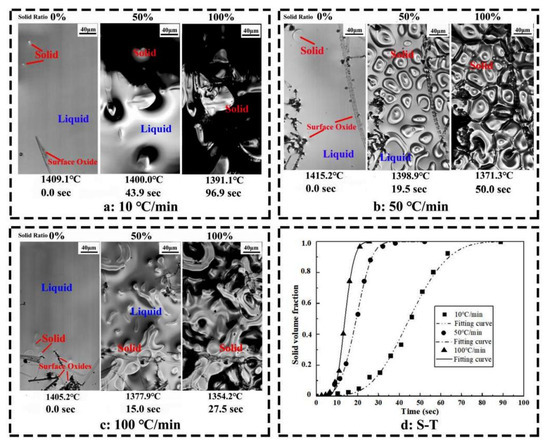
Figure 1.
Solidification process of Ce-HMASS sample observed in situ via HT-LSCM. (a) cooled at 10 °C/min, (b) cooled at 50 °C/min, (c) cooled at 100 °C/min, and (d) fitted curves of the solid volume fraction as a function of time.
Table 2.
Analysis results of Ce-HMASS sample solidification process.
Using the mathematical method to analyse the solidification process is widely accepted. Many researchers propose various models involving the phase transition model [24], solute segregation/redistribution model [25], dendrite growth model [26] and other models. Polycrystalline solidification is a first-order phase transition that proceeds via nucleation and growth. The kinetics of such transformations is often described in terms of the Johnson–Mehl–Avrami–Kolmogorov (JMAK) theory [24]. The JMAK equation is commonly expressed as Equation (1), where Y is solid phase proportion, t is time, k is rate constant for solidification and n is Avrami exponent. The solid volumes in each case have been obtained using the software ImageJ. The solid volume fraction versus time is plotted in Figure 1d. The fitting results are shown in Table 2.
Y = 1 − exp(−ktn)
The Avrami exponent n can be used to analyze the nucleation mechanism. The value of n is 3.63 for the cooling rate of 10 °C/min, 3.57 for 50 °C/min and 3.55 for 100 °C/min, respectively. The Avrami exponent 4 > n > 3 indicates site saturation plus avrami nucleation as nucleation mechanism, which has a decreasing nucleation rate after the initial nucleation [27]. This indicates that the nucleation mode for Ce-HMASS steel is site saturation plus avrami nucleation during solidification. However, the cooling rate does not change the nucleation mode. The rate constant k represents the velocity at which the phase transition from liquid to solid occurs. The rate constant k of Ce-HMASS sample is increased from 1.05 × 10⁻⁵ to 5.95 × 10⁻⁵ with the increase of cooling rate. Thus, the cooling rate has a significant effect on the velocity of HMASS solidification in Ce-HMASS.
3.2. The Combined Effect on Austenite Nucleation and Growth Morphology of Austenite during Solidification in Ce-HMASS
The nucleation site density is measured from the HT-LSCM observation pictures and is shown in Figure 2. The nucleation density increases with the cooling rate in the Ce-HMASS sample. The nucleation number density (10 s after initial nucleation) in the Ce-HMASS sample under the cooling rate of 10 °C/min, 50 °C/min and 100 °C/min is 53.2/mm2, 302.2/mm2 and 440.3/mm2, respectively. The thermal undercooling of liquid steel, which increases with the cooling rate, dominates the austenite nucleation during solidification. Furthermore, the high cooling rate is beneficial to the release of latent heat of solidification, which could further promote the follow-up nucleation.
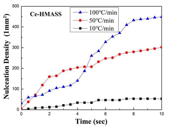
Figure 2.
The evolution of nucleation sites’ density under different cooling rates.
A special austenite grain growth behavior was observed in Figure 1b,c. Thus, two in situ observation tests under the cooling rate of 50 °C/min and 100 °C/min were analyzed in detail. The typical growth process of a single grain in the Ce-HMASS sample under the cooling rate of 50 °C/min and 100 °C/min is shown in Figure 3.
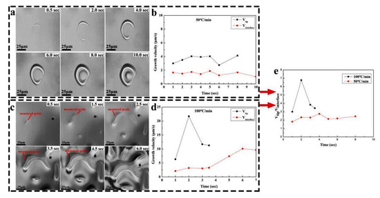
Figure 3.
HT-LSCM observation of the growth process of a single austenite grain cooled and growth velocity of a single grain. (a,b) for 50 °C/min, (c,d) for 100 °C/min, and (e) the ratio of the growth velocity in tip in between interface.
The cerium element would enrich in the solid–liquid interface due to the low solubility in austenite, which could create a constitutional undercooling zone at the front of the solid/liquid (S/L) interface and further reduce the growth velocity for austenite grain growth. X. Yue [28] indicates that the growth rate of the solid phase is gradually becoming slow along with the increasing curvature radius. The smaller the radius of curvature of the solid phase, the faster the growth rate reaches. In addition, the density of cerium atoms is much lower in the interior of the liquid zone than at the interface. Thus, the primary austenite has a much larger growth velocity at the tip than in the middle.
As shown in Figure 3a, the primary austenite is observed in a crescent shape, and then it bends to form a circle shape. After forming a circle-shaped primary austenite, the primary consumes all the liquid phase inside the circle and grows outward until it touches other primary phases. A constant growth velocity in the interface is shown in Figure 3b, and the value is about 2 μm/s. However, the growth velocity in the tip is larger than in the interface, and could reach 4 μm/s in the early stage of grain growth. The velocity in the tip decreases as the thin crescent-shaped primary broadens. The primary grain will bend inward due to the growth of the internal and external interfaces. After bending, the growth velocity in the tip increases again. The tips in the individual grains then quickly grow together, giving the grains a circular shape.
As shown in Figure 3c, the primary austenite would grow to a rod shape with the cooling rate increasing to 100 °C/min. The primary austenite has a tendency to grow together when its tips touch each other during the solidification process. A large number of nucleation sites would appear under the high cooling rate, which would make primary austenite grains easy to be combined together and reduce the ability to refine the solidified structure. As shown in Figure 3d, the growth velocity in the interface of the primary austenite grain is around 2.5 μm/s in the early growth stage. However, the growth velocity in the tip has a significantly higher value than in the interface and would quickly increase to above 20 μm/s. The velocity of the middle part increases significantly after multiple grains fuse together at the tip. The velocity ratio defined as the ratio of the growth velocity in the tip in between the interface, under the cooling rate of 50 °C/min and 100 °C/min, are shown in Figure 3e. The growth morphology of primary austenite grains is controlled by the velocity ratio and changes from crescent-shaped to rod-shaped, as the velocity ratio increases from around 2 to around 7.
The final solidified microstructure of the Ce-HMASS sample under the cooling rate of 50 °C/min obtained from HT-CLSM is shown in Figure 4. The obtained sample has a fine-grained microstructure with equiaxed grains with the average grain size that ranged from 40 to 100 μm. Thus, medium nucleation densities with crescent shape grains make the final solidified microstructure obtain fine equiaxed crystal grains under the cooling rate of 50 °C/min.
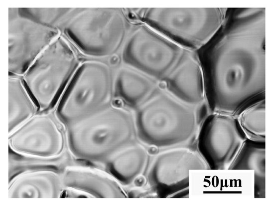
Figure 4.
The final solidified microstructure of the Ce-HMASS sample under the cooling rate of 50 °C/min obtained from HT-CLSM.
When the cooling rate increases to 100 °C/min, a large number of nucleation sites with a rod shape make primary grains easy to be combined together, which would reduce the ability of the grain refining. Due to the HT-LSCM not being able to distinguish the grain boundary after complete solidification, a metallographic image of the Ce-HMASS sample under the cooling rate of 100 °C/min was given to confirm grain the status and shown in Figure 5. Multiple large grains and lots of single equiaxed grains were observed, which lead to non-uniform grain distributions. Thus, the grain refining effect of the cerium addition is not obvious under the cooling rate of 100 °C/min. The phenomenon of austenite grains combined together during the growth process is confirmed in Figure 5. In summary, the final grain size of the solidified structure depends not only on the occurrence of nucleation, but also on the process of primary grain growth. Thus, simply increasing the cooling intensity is inadequate to refine the equiaxed grain in Ce-HMASS.
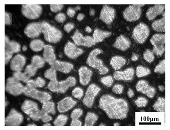
Figure 5.
The final solidified microstructure of the Ce-HMASS sample under the cooling rate of 100 °C/min.
3.3. Influence of Cooling Rate on Element Partition and Redistribution in Ce-HMASS
The directional solidification technique can provide a stable solid–liquid interface at a constant cooling rate, which has important implications for analyzing elemental distributions. First, the morphologies of the solid–liquid interface of the directionally solidified samples under different cooling rates are shown in Figure 6. With the increase of the pulling rate from 15 μm/s to 130 μm/s, the solidified structure gradually changed from the coarse-free dendrite interface to a fine dendrite interface. The average primary and secondary dendrite spacings are measured according to the SEM images. With the increase in the pulling rate, the primary dendrite spacing of the solidified structure decreased from 210 ± 23.14 μm to 144 ± 14.51 μm, and the secondary dendrite spacing of the solidified structure decreased from 52.3 ± 8.31 μm to 17.9 ± 2.83 μm. Thus, the high cooling rate could refine the grain structure.
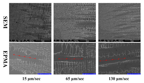
Figure 6.
The microstructure of solid–liquid interface under different pulling rate.
The origin of micro-segregation comes from the partitioning of the solute between a solid and liquid during a crystal growth [29]. The partition coefficient of ki (ki = , Ci is the measured content of element i in the primary dendrites, is the initial content of element i), which can be obtained by the measured content in the primary dendrites. The chemical composition at the center of the primary dendrites would be stable and could be measured by using EPMA, and the result is shown in Table 3. The average contents of Mo and Cr in the columnar crystal center of the Ce-HMASS sample at the pulling rates of 15 μm/s, 65 μm/s and 130 μm/s are 3.718 ± 0.050 wt% and 19.329 ± 0.064 wt%, 3.848 ± 0.044 wt% and 19.391 ± 0.090 wt%, 3.862 ± 0.079 wt% and 19.467 ± 0.066 wt%, respectively. As the pulling rate increased from 15 μm/s to 130 μm/s, the solute partition coefficient of Mo element increased slightly, from 0.612 to 0.644, and the relative amount changed by 5.22%. Under different pulling rate conditions, the solute partition coefficient of Cr elements remained essentially unchanged at 0.97, with a relative change of 0.62%. Therefore, compared with the Cr element, the solute partition coefficient of Mo element is more sensitive to the change of the pulling rate. Increasing the cooling rate is beneficial to improve the micro-segregation of Mo, but the effect of this improvement is limited.
Table 3.
Elemental solute partition coefficients during solidification.
Element redistribution is the result of the superposition of back-diffusion onto the micro-segregation [29]. In order to characterize the element redistribution degree, RD ((, is the maximum element content in interdendritic, is the minimum element content in dendrite arm) was measured by EPMA point analysis. The measurement results are shown in Table 3. With the increase in the pulling rate from 15 μm/s to 130 μm/s, the redistribution degree of Mo element in the solidification structure increased from 2.33 to 3.80, and the redistribution degree of the Cr element increased from 1.15 to 1.21. As a result, the degree of element redistribution of the solidified structure gradually increases as the pulling rate increases.
3.4. Influence of Cooling Rate on Phase Microstructure Evolution in Ce-HMASS
The cross-section SEM-BSED images and EBSD phase distribution results of the directional solidification samples under different pulling rates are shown in Figure 7. As shown in Figure 7a–c, as the pulling rate increases, the size of the second phase in the solidified structure gradually decreases, and the number of the second phase gradually increases. The contrast difference between the second phase and the matrix in the 130 μm/s sample is obvious. The EBSD technique was used to determine the phase distribution of the solidification structure in the cross-section of the three samples, as shown in Figure 7d–f. The second phase in the solidification structure is mainly ferrite under the pulling rate of 15 μm/s and 65 μm/s and would change mainly to the σ phase at 130 μm/s.
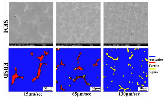
Figure 7.
EBSD phase distribution images for Ce-HMASS steel under different pulling rate.
From the EBSD phase distribution diagram, the second phase proportion of the solidified structure was determined to change with the pulling rate, as shown in Figure 8. The proportion of the ferrite phase in the solidification structure is negatively correlated with the pulling rate. As the pulling rate increases from 15 μm/s to 130 μm/s, the proportion of ferrite phase decreases from 6.6% to 0.
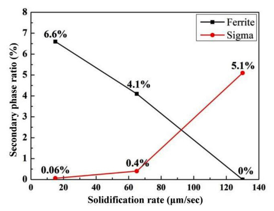
Figure 8.
Effect of pulling rate on the proportion of the second phase.
The proportion of σ phase in the solidification structure is positively correlated with the pulling rate. As the pulling rate increases from 15 μm/s to 65 μm/s, the proportion of σ phase in the steel increases slightly, and the second phase of the solidified structure is mainly ferrite. When the pulling rate reaches 130 μm/s, the ferrite phase of the solidified structure basically disappears completely, and the proportion of the σ phase reaches 5.1%.
The thermodynamic solidification path for 6Mo HMASS is analyzed in our former study and reveals that L → L + γ → L + γ + δ → L + γ + δ + σ [5]. The δ phase is precipitated through a divorced eutectic reaction of L → γ + δ. The nucleation of δ phase in each individual droplet is the restrictive step for δ precipitate. For Ce containing steel, Ce atoms can be enriched in the interdendritic solute-rich liquid and solid–liquid interface due to the low solubility in austenite, which could accelerate δ nucleation, and transforms the secondary phase from σ to δ in 6Mo HMASS. The pulling rate is increased, allowing the dendrite to grow even faster and reducing the solidification time. The function of Ce induced ferrite precipitation at the end of the solidification process can become difficult, as the kinetic condition gradually worsens. Thus, the increasing solidification rate could postpone the precipitation reaction of the ferrite phase and result in further enrichment of Mo in the liquid phase, as shown in Table 4. Finally, the secondary phase in Ce-HMASS would change from δ to σ with the increase in the cooling rate. Thus, the function of Ce promotes the main secondary phase change from σ phase to δ phase in the final solidified structure, which is mainly suitable for medium and low cooling rate.
Table 4.
Average Mo and Cr element content in the second phase wt%.
4. Conclusions
The effect of variations in the cooling rate on the solidification of the Ce-HMASS melt has been investigated by in situ investigations and theoretical approaches. The main results are summarized as follows:
- Cerium addition at high cooling rates is highly favorable for austenite nucleation and has a significant effect on the growth of primary austenite grains. The final nucleation site density would increase from 53.2/mm2 to 440.3/mm2 with the cooling rate increase from 10 °C/min to 100 °C/min in the Ce-HMASS sample. The growth morphology of the primary austenite grain is controlled by the velocity ratio of tip with interface and would change from a crescent shape to stripe shape, with the velocity ratio increasing from around 2 to around 7.
- Simply increasing the cooling rate is inadequate to refine the equiaxed grain in Ce-HMASS. Medium nucleation densities with crescent shape grains make the final solidified microstructure obtain fine equiaxed crystal grains under the cooling rate of 50 °C/min. When the cooling rate increases to 100 °C/min, a large number of nucleation sites with stripe shape grains would make primary grains easily combine together, which would reduce the ability of the refined grain.
- Increasing the cooling rate is beneficial to improve the solute redistribution of the Mo element at the solid–liquid interface, but the effect of this improvement is limited. As the pulling rate increased from 15 μm/s to 130 μm/s, the solute partition coefficient of Mo element increased slightly, from 0.612 to 0.644, and the relative amount changed by 5.22%. However, the micro-segregation degree between dendrites in the solidified structure gradually intensifies with the increase in the pulling rate. The segregation ratio of Mo increased from 2.33 to 3.80 and that of Cr from 1.15 to 1.21.
- The function of Ce promotes the main secondary phase change from σ phase to δ phase in the final solidified structure, and is mainly suitable for the medium and low cooling rate. The increasing pulling rate could postpone the precipitation reaction of the ferrite phase and result in the further enrichment of Mo in the liquid phase.
Author Contributions
Conceptualization, Q.W. and W.Z.; methodology, Q.W. and L.W.; validation, Q.W.; formal analysis, W.Z.; investigation, Q.W., L.W. and W.Z.; resources, Q.W. and L.W.; writing—original draft preparation, Q.W.; writing—review and editing, L.W.; visualization, W.Z. and L.W.; supervision, L.W. and K.C.; funding acquisition, Q.W., K.C. and L.W. All authors have read and agreed to the published version of the manuscript.
Funding
This research was funded by “the National Nature Science Foundation of China, grant number U1810207 and 51922003” and “the Natural Science Foundation of Hebei Province, grant number E2021208017”.
Data Availability Statement
Not applicable.
Conflicts of Interest
The authors declare no conflict of interest.
References
- Zhang, S.; Jiang, Z.; Li, H.; Feng, H.; Zhang, B. Detection of susceptibility to intergranular corrosion of aged super austenite stainless steel S32654 by a modified electrochemical potentiokinetic reactivation method. J. Alloys Compd. 2017, 695, 3083–3093. [Google Scholar] [CrossRef]
- Han, Y.; Wu, H.; Zhang, W.; Zou, D.; Liu, G.; Qiao, G. Constitutive equation and dynamic recrystallization behavior of as-cast 254SMO super-austenite stainless steel. Mater. Des. 2015, 69, 230–240. [Google Scholar] [CrossRef]
- Cui, Y.; Qurashi, M.S.; Wang, J.; Chen, T.; Bai, J.; Dong, N.; Zhang, C.; Han, P. Effect of Solution Treatment on the Microstructure and Performance of S31254 Super austenite Stainless Steel. Steel Res. Int. 2019, 90, 1900041. [Google Scholar] [CrossRef]
- Bai, J.; Cui, Y.; Wang, J.; Dong, N.; Qurashi, M.S.; Wei, H.; Yang, Y.; Han, P. Effect of Boron Addition on the Precipitation Behavior of S31254. Metals 2018, 8, 497. [Google Scholar] [CrossRef]
- Wang, Q.; Wang, L.; Sun, Y.; Zhao, A.; Zhang, W.; Li, J.; Dong, H.; Chou, K. The influence of Ce micro-alloying on the precipitation of intermetallic sigma phase during solidification of super-austenite stainless steels. J. Alloys Compd. 2020, 815, 152418. [Google Scholar] [CrossRef]
- Tehovnik, F.; Burja, J.; Arh, B.; Vode, F. Precipitation of σ phase in superaustenite stainless steel UHB 904L. Metalurgija 2017, 56, 63–66. [Google Scholar]
- Wang, Z.; Shi, C.; Wang, S.; Li, J.; Zhu, X. Evolution and Formation of Non-Metallic Inclusions during Electroslag Remelting of Ce-Bearing 15Cr-22Ni-1Nb austenite Heat-Resistant Steel. Metals 2022, 12, 2094. [Google Scholar] [CrossRef]
- Gong, W.; Wang, P.; Zhang, L.; Jiang, Z. Effects of Ce on microstructure and mechanical properties of LDX2101 duplex stainless steel. Metals 2020, 10, 1233. [Google Scholar] [CrossRef]
- Luo, S.; Shen, Z.; Yu, Z.; Wang, W.; Zhu, M. Effect of Ce addition on inclusions and grain structure in gear steel 20CrNiMo. Steel Res. Int. 2021, 92, 2000394. [Google Scholar] [CrossRef]
- Wang, H.; Bao, Y.; Zhi, J.; Duan, C.Y.; Gao, S.; Wang, M. Effect of rare earth Ce on the morphology and distribution of Al2O3 inclusions in high strength IF steel containing phosphorus during continuous casting and rolling process. ISIJ Int. 2021, 61, 657–666. [Google Scholar] [CrossRef]
- Chen, X.; Li, Y. Fracture toughness improvement of austempered high silicon steel by titanium, vanadium and rare earth elements modification. Mater. Sci. Eng. A 2007, A444, 298–305. [Google Scholar] [CrossRef]
- Cai, Y.; Luo, Z.; Huang, Z.; Zeng, Y. Effect of cerium oxide flux on active flux TIG welding of 800 MPa super steel. J. Mater. Process. Technol. 2016, 230, 80–87. [Google Scholar] [CrossRef]
- Torkamani, H.; Raygan, S.; Garcia Mateo, C.; Rassizadehghani, J.; Vivas, J.; Palizdar, Y.; San-Martin, D. The influence of La and Ce addition on inclusion modification in cast niobium microalloyed steels. Metals 2017, 7, 377. [Google Scholar] [CrossRef]
- Wang, Y.; Liu, C. Evolution and deformability of inclusions in Al-killed steel with rare earth-alkali metals (Ca or Mg) combined treatment. J. R. Earths 2022, in press. [Google Scholar] [CrossRef]
- Sun, M.; Jiang, Z.; Li, Y.; Chen, C.; Ma, S.; Ji, Y.; Wang, J.; Liu, H. Effect of Sulfur Content on the Inclusion and Mechanical Properties in Ce-Mg Treated Resulfurized SCr420H Steel. Metals 2022, 12, 136. [Google Scholar] [CrossRef]
- Zhang, S.; Yu, J.; Li, H.; Jiang, Z.; Geng, Y.; Feng, H.; Zhang, B.; Zhu, H. Refinement mechanism of cerium addition on solidification structure and sigma phase of super austenite stainless steel S32654. J. Mater. Sci. Technol. 2022, 102, 105–114. [Google Scholar] [CrossRef]
- Zhang, Y.; Xiao, J.; Liang, J.; Pei, W.; Liu, P.; Zhang, W.; Zhao, A. Effect of rare earth elements on the segregation behavior and microstructure of super austenite stainless steel. J. Mater. Res. Technol. 2022, 19, 20–29. [Google Scholar] [CrossRef]
- Zhang, R.; He, J.; Xu, S.; Zhang, F.; Wang, X. The roles of Ce and Mn on solidification behaviors and mechanical properties of 7Mo super austenite stainless steel. J. Mater. Res. Technol. 2022, 22, 1238–1249. [Google Scholar] [CrossRef]
- Zhang, S.; Li, H.; Jiang, Z.; Feng, H.; Wen, Z.; Ren, J.; Han, P. Unveiling the mechanism of yttrium significantly improving high-temperature oxidation resistance of super-austenite stainless steel S32654. J. Mater. Sci. Technol. 2022, 115, 103–114. [Google Scholar] [CrossRef]
- Wang, L.; Li, Z.; Hu, X.; Lv, B.; Chen, C.; Zhang, F. Hot deformation behavior and 3D processing map of super austenite stainless steel containing 7Mo–0.46 N–0.02 Ce: Effect of the solidification direction orientation of columnar crystal to loading direction. J. Mater. Res. Technol. 2021, 13, 618–634. [Google Scholar] [CrossRef]
- Xu, P.; Ma, J.; Jiang, Z.; Li, H.; Zhang, Y.; Dong, N.; Han, P. Effect of B and Ce on the grain boundary segregation of Mo-rich phases in super-austenite stainless steels. Appl. Phys. A 2022, 128, 34. [Google Scholar] [CrossRef]
- Wang, Q.; Wang, L.; Zhang, W.; Li, J.; Chou, K. Effect of Cerium on the austenite Nucleation and Growth of High-Mo austenite Stainless Steel. Metall. Mater. Trans. B 2020, 51, 1773–1783. [Google Scholar] [CrossRef]
- Wang, Q.; Wang, L.; Liu, Y.; Chou, K.C. Using Ce to modify Al2O3 inclusion in spring steel. J. Min. Metall. Sect. B Metall. 2017, 53, 365–372. [Google Scholar] [CrossRef]
- Christian, J.W. The theory of transformations in metals and alloys. In Equilibrium and General Kinetic Theory, 2nd ed.; Pergamon Press: Oxford, UK, 1975; 564p. [Google Scholar]
- Wołczyński, W. Back-diffusion in crystal growth. Eutectics. Arch. Metall. Mater. 2015, 60, 2403–2407. [Google Scholar] [CrossRef]
- Kim, B. Development of Macrosegregation during Solidification of Binary Metal Alloys; The Pennsylvania State University: State College, PA, USA, 2002. [Google Scholar]
- Wang, M.; Chen, L.; Wang, Z.; Bao, E. Influence of rare earth elements on solidification behavior of a high speed steel for roll using differential scanning calorimetry. J. R. Earths 2011, 29, 489–493. [Google Scholar] [CrossRef]
- Yue, X.D.; Jin, G.C.; Chen, S.Y.; Chang, G.W. In Situ Observation of Growth Process of δ Phase of 0.15% C Carbon Steel during Solidification. In Advanced Materials Research; Trans Tech Publications Ltd.: Wollerau, Switzerland, 2011; Volume 299, pp. 341–344. [Google Scholar]
- Wołczynski, W. Pattern Selection in the Eutectic Growth-Thermodynamic Interpretation. Arch. Metall. Mater. 2020, 65, 653–666. [Google Scholar]
Disclaimer/Publisher’s Note: The statements, opinions and data contained in all publications are solely those of the individual author(s) and contributor(s) and not of MDPI and/or the editor(s). MDPI and/or the editor(s) disclaim responsibility for any injury to people or property resulting from any ideas, methods, instructions or products referred to in the content. |
© 2023 by the authors. Licensee MDPI, Basel, Switzerland. This article is an open access article distributed under the terms and conditions of the Creative Commons Attribution (CC BY) license (https://creativecommons.org/licenses/by/4.0/).