Abstract
This research presents the microstructural and mechanical evolution throughout the welded seam of an austenitic stainless steel (ASS) tube. It was found that the main hardness decrement occurred in the fusion zone (FZ), followed by the heat-affected zone (HAZ) and the base material (BM). Optical microscopy indicated a dendritic structure in FZ and heterogeneous austenitic grain size from the HAZ towards the BM, ranging from 100 µm to 10 µm. The welding process generated an intense texture around the FZ and the HAZ, while the BM still showed an extrusion-like texture. In terms of mechanical behavior, the largest austenite grain size in the FZ led to the lowest strength and ductility of all zones due to the earliest strain localization manifested by heterogeneous strain distribution. However, the strain localization in all zones appeared after 0.4 true strain, indicating an overall good ductility of the seam. These high values were related to two microstructure characteristics: (1) the 10% δ-ferrite after solidification in the FZ favored by the relationship that delayed the crack propagation along the austenite grains and (2) the heterogeneous microstructure made up of soft austenite and hard martensite in the HAZ and BM producing multiple strain concentrations. Kernel Average Misorientation (KAM) maps obtained by Electron Back-Scattering Diffraction (EBSD) allowed observing higher internal misorientations in the FZ than in the HAZ due to interconnected walls between the δ-ferrite grains. However, the largest KAM values were observed in the BM between γ-austenite and the deformation-induced α’-martensite phases. X-ray diffraction revealed that the residual stresses in the cross-section of the welded seam were compression-type and then switched to tension-type in the outer surface.
1. Introduction
Welding as a technological manufacturing process that requires knowledge of the properties across the welded seam to fulfill the load applications, corrosion resistance, fatigue strength, and safety requirements, i.e., the joint quality. It is so that welding process investigations represent a comprehensive research field in metallurgy and materials science, where it is sought a better understanding of different hardening and softening phenomena, as well as the relationship between processing parameters and microstructure changes that influence the welded joint integrity. Therefore, chemical compositions of the elements to joint, type of welding process, protecting atmosphere, heat input, and filler material are vital parameters defining the quality of the welded seam [1,2,3].
Within the significant number of welding processes, Gas Tungsten Arc Welding (GTAW), also known as Tungsten Inert Gas (TIG), stands out due to its ability to operate with and without filler material, allowing to obtain sound quality and free-of-defects weld seams of similar and dissimilar materials [4]. These advantages make the GTAW process ideal to be used in several industrial applications, such as applying an overlay, fill pass welding, and welding by root joints [4,5]. For these reasons, the GTWA process has been used to manufacture seam tubes, repairs, and joints between tubes to increase their length [6].
When it comes to high-quality and performance tubes, steels offer a wide diversity of properties that fit many applications. For example, stainless steels include a group of alloys covering an ample and diverse range of properties, starting with corrosion resistance, formability capacity, and thermal stability at high and cryogenic temperatures. Additionally, they are inert materials, and due to their low carbon content, most stainless steels show good welding behavior [7,8,9]. These distinct properties are highly related to alloying elements such as C, Cr, and Ni that define the steel phases and the solidification mechanism [10,11].
Stainless steel weld seam tubes can be found in many industrial types of equipment. Some examples are the chemical industry, petroleum and gas transport, paper factories, the electric industry, medical implements, the food industry, construction and buildings, aerospace applications, textile industries, and nuclear and power plants [12,13,14]. Thus, the study, comprehension, and evaluation of the weld seam tubes’ properties under different environments and working conditions are essential to ensure optimal performance.
Some authors have studied the effect of different processing variables and how these variables affect the intergranular and pitting corrosion resistance in stainless steel, considering different temperature ranges and measurement techniques [15,16]. For example, Kain et al. [17] studied the stress corrosion cracking phenomenon in stainless steels, evaluating the composition, stacking fault energy, microstructure, and environmental conditions. In this study, they concluded that a high fraction of low-energy grain boundaries was helpful to counteract the stress corrosion cracking sensibilization. On the other hand, Böhner et al. [18] evaluated the effect of the martensitic transformation on the steel fatigue life applying monotonic and cyclic loads. Their principal findings were that under cyclic loads, the critical nuclei for the martensitic transformation were independent of ultrafine-grained microstructure. However, the opposite happened with monotonic loads, where the ultrafine-grained microstructure was more favorable for the martensitic transformation than its coarse-grained counterpart.
Martensitic transformation in stainless steels is of great importance because the steel can combine hard and soft phases such as martensite and austenite that help to improve the steel fatigue life delaying the crack propagation due to a local hardening effect [19]. This is why studying the phase transformations in the welding process is a key parameter defining the joint properties. For example, Lima et al. [20] demonstrated grain growth during the temperature rise in the Heat Affected Zone (HAZ) and the Cr carbides nucleation that diminished the joint mechanical strength. Moreover, Muthupandi et al. [21] proved that the chemical composition of duplex stainless steel has a stronger influence on the ferrite–austenite relation than the cooling rate during the welding process. Several authors have pointed out that after solidification, the ferrite solidification in the weld seam of austenitic stainless steel alloyed with CrMnNi helps to improve the hot cracking resistance [22,23].
Welding processes involve considerable microstructural modifications around the weld seam. Thus, different zones are identified. For instance, the Fuzion Zone (FZ), where the highest temperatures are reached because the fusion of the materials is necessary, giving rise to a dendritic microstructure. Then, the HAZ, where phase transformations and grain growth can occur. Therefore, studying the microstructure evolution, mechanical properties, and the mechanism behind the welding process of stainless steel is a topic of interest that guarantees the integrity of elements to avoid failure. In this context, it is crucial to determine in detail the properties of each region from the FZ to the Base Material (BM) passing thorough the HAZ.
This investigation addresses the microstructural and mechanical heterogeneity of a weld seam obtained by the GTAW in austenitic stainless steel (ASS) 304L. To apport a better understating of the steel properties subject to a welding process, the microstructure heterogeneity between the FZ and the BM was thoroughly studied by Optical Microscopy (OM) and electronic microscopy using Electron Backscattering Diffraction (EBSD). Furthermore, hardness profiles and micro-tensile tests for each zone were evaluated regarding the weld joint mechanical behavior. Thus, the critical points and the responsible softening and hardening mechanisms across the weld seam were established.
2. Materials and Methods
2.1. As-Received Material
The as-received material was an extruded tube of 100 mm exterior diameter and 4 mm in thickness. The BM steel corresponds with a 304L ASS with the chemical composition indicated in Table 1. The tube was cut and welded around its perimeter, as shown in Figure 1a. A small cross-section of the weld seam in the radial direction (RD)-extrusion direction (ED) plane was extracted to analyze the microstructure and the different zones generated by the heat transfer, as indicated in Figure 1b,c, respectively. The GTWA process in a girth configuration with a current of 250 A, voltage of 27 V, and non-consumable 2.4 mm diameter electrode was employed to weld the pieces. Argon flowing at a rate of 15 L/min was used as a protector atmosphere, and the Filler Material (FM) with a chemical composition indicated in Table 1 (we did not apply weld root protection to purge the oxygen inside the tube). The main differences between the base material and the filler material are concentrated in the Mn content, which is considerably higher in the filler material.

Table 1.
Chemical composition for the studied steel base material (BM) and filler material (FM) (wt. %).
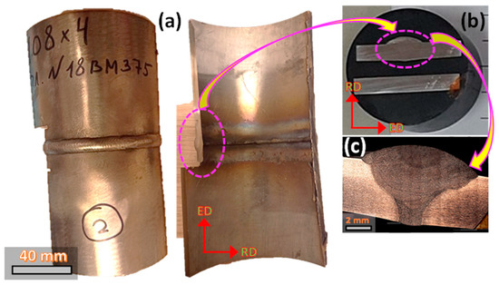
Figure 1.
(a) welded tube, (b) welded seam section, and (c) welded seam microstructure.
2.2. Microstructure Characterization
The microstructure of a representative area of the welded joint and the BM was characterized by cutting the tube along its longitudinal direction (LD) to observe the weld seam, and BM cross sections, as indicated in Figure 1. Microstructural changes in the FZ, HAZ, and BM were observed through OM using an optical microscope Zeiss AX10 (ZEISS Microscopy, Oberkochen, Germany), as shown in Figure 2. The sample surfaces were prepared by mechanical grinding following standard metallographic procedures. As a first step, the surfaces were polished with SiC sandpapers with granulometry ranging between 400 and 2500. Then, a fine polishing with diamond suspensions of 9 µm, 6 µm, 3 µm, and 1 µm was applied. Then, the sample surface was electropolished with 10% aqueous oxalic acid at room temperature for 5 s to reveal the microstructure and to minimize any phase transformation induced by local deformations. Finally, ImageJ software was used estimate the average grain size from optical micrographics by derivation of the equivalent diameter of each grain [24].
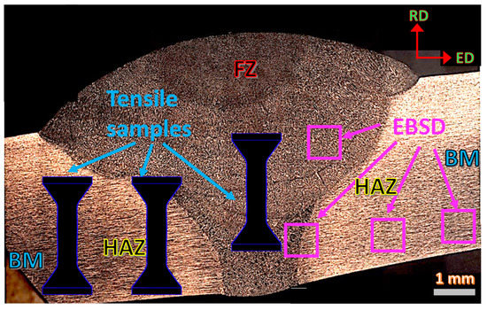
Figure 2.
Analyzed zones on the weld seam with indication of the areas were mini-tensile samples were extracted (all the tensile samples were cut with the same orientation; the tensile test drawings are scaled 1:2).
For a more detailed microstructure, texture, and phases transformations characterization on the different zones, a TSL-OIM EDAX EBSD system mounted on an FEG SEM Quanta 200 scanning electron microscope (SEM, manufactured by ThermoFisher scientific, Waltham, MA, USA) was used. The sample preparation was similar to the OM, but with the addition of one more polishing step using 0.03 µm particle size colloidal silica that does not crystalize. This procedure was carried out in a vibratory polishing machine for 3 h and subsequently cleaned in ultrasonic for 1 h before taking the sample inside the microscope chamber. The EBSD scans were obtained in different zones between the weld seam and BM to reveal the microstructure heterogeneity, as displayed in Figure 2. For the texture and microstructure analysis, the EBSD scans were obtained with 1 µm and 0.1 µm step sizes, respectively. It is worth mentioning that the indexation rate in all the scans was over 90%, so the non-indexed points were corrected by the grain dilation method, and grains with less than 2 pixels were excluded from any statistical analysis. The data were processed by TSL-OIM 7.1 and MTEX toolbox software (version 5.7.0, Ralf Hielscher, Freiberg, Germany) [25]. Grain boundaries were divided into two families: high angle grain boundaries (HAGB) for those boundaries with misorientations higher than 15° and low angle grain boundaries (LAGB), also referred to as subgrains, with misorientations between 3° and 15°. Grain size and Kernel Average Misorientation (KAM) profiles were plotted following the methodology proposed by Muñoz et al. [26]. For the sake of statistics, scan areas of 500 µm × 500 µm were considered for the texture analysis.
In addition to the OM and EBSD studies, X-ray diffraction analyses were carried out on the FZ and the BM zones. The diffractograms for each zone were obtained by means of a Philips X pert Pro MPD diffractometer with Cu-Kα radiation at 40 kV and 15 mA, a polycapillary fiber optic concentrator device (called X-ray Lens by Panalytical, Malvern Panalytical Ltd, Malvern, UK), and Soller slits on the outgoing X-ray beam reaching a Xe gas detector. The whole setup has the advantage of a high intensity parallel beam with superb averaging capabilities. Residual strains were measured, and stresses were calculated by using the proper polycrystalline isotropic elastic constants for 304 stainless steel by the sin2ψ method. The method allows the measurement of stresses without knowing the precise value of dhklo (interplanar distance) for different family planes. That is particularly useful for studying materials with low anisotropy as FCC homogeneous metals and alloys. The intensities in the 2θ range between 38°–118° were measured with a scan step size of 0.02°. For the volumetric fraction calculation of each phase, it was assumed proportional to the integrated intensity of all its peaks, as indicated by the following equation [27]:
where represents the number of integrated peaks for each phase; is the integrated intensity; refers to the scattering factor. All the diffractograms were analyzed using Maud software [28], which allows for determining the dislocation density () considering the peak broadening according to the following equation [29]:
where is the lattice strain; the Burgers vector; is the crystal size.
2.3. Mechanical Characterization
Uniaxial tensile tests and hardness measurements evaluated the mechanical response for all the zones. Vickers hardness profiles were built inside the FZ, across the fusion line between the FZ and the HAZ and on the BM for better mechanical characterization. All the hardness measurements used a load of 1.97 N and a dwell time of 15 s. To avoid the strain field influence from the previous hardness mark, every new hardness measurement was taken at a distance of two times the size of the last mark. For the uniaxial tensile tests at room temperature, two scaled bone shape samples with gauge dimensions of 4 mm × 1.3 mm × 2 mm were extracted from each zone (see Figure 2) using electrode discharge machining (EDM). All the tensile samples were tested in a universal Instron machine with a constant strain rate of 1 × 10⁻³ s−1. During the tensile tests, the strain and the deformation maps were recorded using the digital image correlation (DIC) method. In this regard, a speckle pattern of black and white spots was painted on the calibrated length of each sample, and pictures were taken every 2 s. The post-processing was conducted with the free software Ncorr (version v1.2.2, Georgia Institute of Technology, Atlanta, GA, USA, http://www.ncorr.com/index.php) [30].
3. Results and Discussion
3.1. Microstructure Evolution
Figure 3a shows the weld seam transversal section after chemical etching, where the main characteristics of the FZ and the HAZ microstructures can be identified. Figure 3b highlights the microstructure profile inside the FZ following the dashed red arrow in Figure 3a. In this profile, distinct microstructural characteristics of the solidified material are noticed. For example, the microstructure in the FZ is fully dendritic in all the sections. Second, the dendritic structure solidified following different behaviors depending on the zone. Larger and narrower dendrites were observed in the middle zone of the FZ than close to the fusion line, where a more equiaxed cellular was observed, as corroborated by the black square insets in Figure 3b. Some authors have found dendritic microstructures in the FZ with cellular and columnar morphologies, either for the δ-ferrite (bcc crystal structure) or for the γ-austenite (fcc crystal structure) in ASS after the welding process [31,32]. The coexistence of various dendritic morphologies in the FZ has been associated with local chemical fluctuations and cooling rate gradients across the FZ [22].
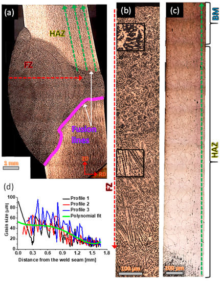
Figure 3.
(a) Weld seam cross section indicating the FZ, HAZ, and BM, (b) microstructural panoramic across the FZ, (c) microstructural panoramic between the HAZ and the BM, and (d) austenitic grain size evolution across the interphase of the FZ and the HAZ until the BM.
Regarding the HAZ and BM microstructure, Figure 3c confirms significant grain size variations from the FZ-HAZ interphase until zones beyond 1 mm far from the fusion line. As expected, heat transfer affects areas closer to the FZ more than the furthest ones. This gave rise to austenitic grain sizes next to the fusion line of 100 µm. Figure 3d plots three grain size profiles following the green dashed arrows indicated in Figure 3a to corroborate the grain size variations. These profiles suggest the existence of grain sizes larger than 100 µm around the FZ-HAZ neighborhoods, which continuously decrease as one moves away from the fusion line reaching average values of 10 µm in the BM. It is worth mentioning that grain size values calculated from OM mainly correspond to the austenite phase. However, the grain size and grain boundaries from other phases, such as δ-ferrite and α’-martensite (bcc crystal structures) coming from the solidification and forming processes, respectively, are not easy to reveal and identify by OM. Even so, it is evident from Figure 3c and Figure 3d that the temperature gradient creates an HAZ that extends beyond 1 mm from each side of the weld seam.
Figure 4 shows SEM images for all the analyzed zones. Figure 4a confirms the solidification of the primary δ-ferrite together with the austenite grains. In the fusion line, Figure 4b allows observing several phases with different morphologies. Austenite is mainly observed on the FZ side, and new microstructural characteristics are noticed on the HAZ. These new characteristics are related to the presence of α’-martensite induced by the tube-forming process. Thus, in the BM zone, two phases can be distinguished following a well-defined orientation, as indicated in Figure 4c. Furthermore, in this figure, grain size differences between the austenite and the martensite suggest microstructure heterogeneity.
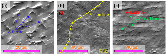
Figure 4.
SEM images for all the analyzed zones. (a) FZ, (b) fusion line defining the border between the FZ and the HAZ, and (c) BM.
For a more detailed microstructure characterization in all the zones, the EBSD maps allowed the phases identification, grain size calculations for all phases, and texture evolution. Thus, Figure 5a through Figure 5d present the phase maps overlaid over the Image Quality (IQ) for the different zones, starting with the FZ until the BM. For example, in the FZ, Figure 5a highlights in blue and red colors the δ-ferrite and γ-austenite phases, respectively. In this figure, it is observed that the dendritic structure corresponds to the primary δ-ferrite phase.
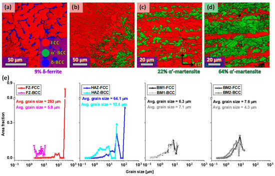
Figure 5.
Identification phase maps overlapped on the image quality map for the (a) FZ, (b) fusion line between the FZ and HAZ, (c) BM1, (d) BM2, and (e) grain size distributions for all the phases in the analyzed zones.
The apparition of δ-ferrite in the FZ confirms the high temperature reached during the fusion. At first glance, Figure 5a suggests that the δ-ferrite solidified around the austenite grain boundaries with an irregular skeletal-type morphology. This phase stretches to the limits with the HAZ until the fusion line, as shown in Figure 5b. From this border forward, the bcc crystal structure corresponds to the α’-martensite due to the deformation-induced phase transformation phenomenon of ASS during the manufacturing process (tube was supplied in a cold extrusion state). According to Shen et al. [33], the amount of α’-martensite in a 304L-ASS is a function of composition, strain, and strain rate.
The way the weld joint has solidified agrees with the relationship that controls the phases present in stainless steels, as indicated in the Schaeffler diagram. Thus, the amount of and can be evaluated by the following equations [34]:
From the chemical composition in Table 1 and using Equations (3) and (4), a value of was obtained. According to Lu et al. [35] and Yazdian et al. [32], if the relationship , the FZ will solidify with the presence of ferrite around the austenite grain boundaries. Given the amounts of and for the studied steel and using the Schaeffler diagram presented in the research work of Quitzke et al. [22], the amount of δ-ferrite should not exceed 10%. This value agrees with the 9% of δ-ferrite calculated by EBSD, as indicated in Figure 5a.
Other factors also help to keep a δ-ferrite fraction in the FZ. For example, since the δ → γ transformation is a diffusion-controlled solid-state transformation, the fast-cooling rates involved in the GTAW process can be responsible for a non-complete austenite transformation. Nevertheless, δ-ferrite can play a positive role in the ASS’ weld seams because it acts as a barrier for crack propagation.
In zones far from the fusion line and the HAZ, in the zone called BM1, which corresponds to the based material that still could be affected by the welding heat, new microstructural characteristics are developed, as indicated in Figure 5c. At this point, the microstructure presents two phases: the austenite (red color) and the bcc crystal structure corresponding to the deformation-induced α’-martensite (green color). Beyond the BM1 zone, i.e., the BM2 zone, Figure 5d shows a mixture of austenite and α’-martensite again, being the latter fraction more dominant.
The development of α’-martensite in stainless steels of the 304L series depends on microstructural parameters such as the stacking fault energy (). A quick measurement of this parameter can be conducted from the steel chemical composition following the equation proposed by Schramm et al. [36]:
Using Equation (5) and the BM chemical composition shown in Table 1, the value for the studied steel is ~15.1 mJ/m2, which can be considered low energy according to Allain et al. [37]. Furthermore, they established for a high Mn steel that twinning was the favorite deformation mechanism when the ranges between 18 mJ/m2–45 mJ/m2, while deformation assisted by dislocation (dislocation glide) required energies above 45 mJ/m2. Therefore, the preferred deformation mechanism at room temperature for the studied steel is the deformation-induced phase transformation, i.e., austenite transforms into martensite.
Moving on to grain size evolution in the different zones, Figure 5e represents the grain size distributions for each zone indicated in Figure 5a to Figure 4d. As a first observation, the grain size distributions for the two phases in the FZ show more than one magnitude order difference between the austenite and δ-ferrite average grain size. These differences suggest a heterogeneous microstructure inside the FZ. Around the fusion line, grain size differences decrease considerably, but the average austenite grain size is almost six times greater than the mix of ferrite and martensite. These fewer differences in the grain size calculations are related to the consideration of α’-martensite, which possesses larger grains than δ-ferrite.
In more distant areas, e.g., BM1 and BM2, the austenitic grain size tends to stabilize around 8 µm, as illustrated in the OM analysis presented in Figure 3d. In the same zones, the martensite grain size decreases from 7 µm to 4 µm, and its fraction increases from 22% to 64%. These grain size and phase volume fraction variations can produce overall grain refinement and material strengthening. Muñoz et al. [38] found a yield strength improvement in an ASS due to the grain refinement after plastic deformation by increasing the martensite fraction. Thus, it is clear that the welded tube microstructure owns different grades of heterogeneity.
The microstructural heterogeneity generated by different phase transformations due to the GTAW welding and the tube forming process can affect the grain size, the grain boundary nature, and the dislocation density, as some researchers have proved [39,40]. In this context, Figure 6 presents the IQ maps together with the different grain boundaries (black and red colors correspond with the HAGB and LAGB, respectively) and the corresponding misorientation angle distributions. As with the grain sizes, Figure 6a through Figure 6d also suggest different amounts of LAGB and HAGB depending on the analyzed zone. The mentioned differences can be interpreted and compared by the misorientation angle distributions. These distributions demonstrate that the HAGB fractions for all phases increase as the distance from the FZ also increases, as illustrated in Figure 6e. This analysis also highlights two things: (1) both phases found the largest LAGB fractions in the FZ, and (2) in each zone, the phases with bcc crystal structure showed the largest LAGB fractions.
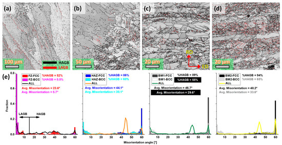
Figure 6.
IQ imagens together with the grain boundaries for the different analyzed zones. (a) FZ, (b) fusion line between the FZ and HAZ, (c) BM1, (d) BM2, and (e) misorientation angle distributions for all the phases in all the analyzed zones.
These observations allow seeing microstructure heterogeneity along the zones and between the phases of each zone. Besides, the most significant fractions of LAGB in the FZ and its neighborhoods are related to a high density of Geometrically Necessary Dislocations (GNDs), which controls the curvature of the grain [41,42,43]. This is because the more intense thermal gradients produce higher residual stresses around the FZ than in the BM. On the other hand, metallic materials with two phases, such as duplex, dual phase, and austenitic stainless steels, present different dislocation densities due to their different capacities to distribute deformation. According to several authors [38,44,45], deformation distribution must also be heterogenous between the two phases leading to additional material hardening. It also demonstrates the creation of plastic gradients around the weld seam and between the phases of each zone.
3.2. Texture Heterogeneity
The preferential crystallographic orientation is closely related to microstructural parameters, such as grain size, dislocation density, and grain boundary orientation, which are influenced by the solidification, thermal gradients, and the tube-forming process. At first glance, the highest texture intensities were observed in the FZ, followed by the zones close to the fusion line and the HAZ, as shown in Figure 7a,b, respectively. However, according to the pole figure, austenite texture for these zones does not follow any specific texture component associated with recrystallization, deformation, or shear mechanism. This is coherent with the solidification process that produced huge austenite grains with random orientations. Conversely, the pole figure for the δ-ferrite indicates more symmetric components in both zones. This is because, in the FZ, the δ-ferrite solidified in the austenite grain boundaries. Furthermore, in the HAZ, texture calculation also considers the α’-martensite, which conserves its preferential orientation towards the Extrusion Direction (ED). In zones BM1 and BM2, the pole figures for both phases indicate symmetric behaviors associated with a monotonic process such as rolling or extrusion, as indicated in Figure 7c,d. Therefore, the tube’s thermal (solidification and recrystallization) and deformation (phase transformation and continuous dynamic recrystallization) history have favored the apparition of different kinds of textures across the FZ, HAZ, and BM.
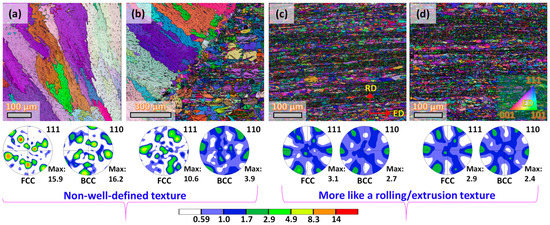
Figure 7.
Inverse pole figure maps and the corresponding pole figures for the fcc and bcc crystal structures. (a) FZ, (b) fusion line between the FZ and HAZ, (c) BM1, (d) BM2.
3.3. Hardness Evolution
As a consequence of the microstructural changes on the weld seam and its surroundings, to determine the joint weak points, the mechanical behavior was analyzed following hardness profiles in three zones, that is FZ, HAZ, and BM. Thus, dashed lines in Figure 8a indicate where the hardness profiles were measured. As a first observation, Figure 8b highlights that the hardness profiles inside the FZ vary significantly over the measured distance with an average value of 183 HV and a standard deviation value of 10 6 HV. This behavior certainly is attributed to the heterogeneous dendritic morphology across the FZ, as indicated in Figure 3b and corroborated by the grain size and grain boundaries evolutions in Figure 5 and Figure 6, respectively. Then, the HAZ hardness profiles show less scatter and higher magnitudes than the FZ (average value of 195 HV and a standard deviation value of 6.5 HV) but lower than the BM (average value of 197 HV and a standard deviation value of 5 HV). The hardness differences between the HAZ and the BM are related to the grain size and the phase volume fraction variations originating from thermal gradients. For example, in the BM, the α’-martensite grain size is the smallest, and this phase represents more than 60%, i.e., the hardest phase is more representative than the softest one, as indicated in Figure 5d. Therefore, based on the hardness evolution, the weld seam’s weakest points are mainly located between the FZ and the HAZ.
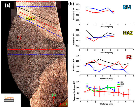
Figure 8.
(a) hardness profiles localization and (b) hardness measurements on the different zones and the average curve for each zone (doted lines in figure (a) do not correspond to the exact path and location where the hardness profiles were obtained, they are just used as an illustration mode).
3.4. Plastic Behavior and Internal Stresses
Uniaxial tensile tests in each zone will be discussed to better understand the microstructural heterogeneity impact on the weld seam mechanical response. Figure 9a presents the engineering (symbol line) and true (line without symbols) stress–strain tensile curves for the FZ, HAZ, and BM, following the sketch in Figure 2. These curves reflect clear ductility and strength variations with the same tendency of the hardness profiles. So, the FZ reaches the lowest mechanical strength and ductility (maximum elongation) values of all three zones with values of ~1100 MPa and ~45%, respectively. In the HAZ, values of ~1300 MPa and 58% are found, while the BM shows the highest properties with values of 1330 MPa and 63% elongation to failure. These mechanical properties confirm that the FZ presents the poorest performance; however, the mechanical strength and ductility values stand out over other 304L ASS with a 100% austenitic microstructure such as the steel studied by Kumar et al. [46].
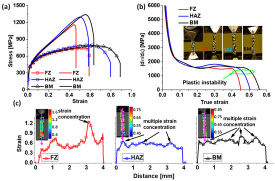
Figure 9.
(a) True and engineering tensile curves, (b) strain hardening rate curves, and (c) strain maps and profiles for the different analyzed zones before the plastic instability starts (the strain profiles were obtained along the vertical direction following the pink color arrow, so distance on X axis means the length of the analyzed zone being 0 in the upper part, i.e., the beginning of the arrow).
The good mechanical performance of the FZ can be associated with the presence of δ-ferrite, which contributes to strength (smaller grain size than austenite) and also acts as a barrier for the crack propagation in the big austenitic grains, delaying the final fracture. Additionally, it has been demonstrated by Kain et al. [17] that δ-ferrite helps to improve the stress corrosion cracking strength. On the other hand, the heterogeneous microstructure in the HAZ and BM made up of austenite and α’-martensite allows good strength and ductility in good ratios. In these cases, the α’-martensite is the phase that retards the plastic instability. This is because the α’-martensite is tougher than the austenite; therefore, for a given plastic deformation, the austenite will assume more plastic deformation than the martensite; i.e., austenite will start to deform plastically ahead of martensite. One example of hetero-deformation is the research work of Li et al. [47] in a 304L ASS with a heterogeneous lamella-type microstructure obtained by rolling and subsequent annealing. In this research, the good strength–ductility ratio was associated with different hardening stages where the accumulation of stacking faults/GNDs and initiation of strain-induced martensitic transformation took place during the tensile test.
Phase transformations and heterogeneous microstructures made up of dissimilar phases with different grain sizes affect the steel hardening capacity, as indicated in Figure 9b. In this figure, the FZ’s strain hardening rate curve decays fast at the beginning of deformation, followed by short plateau regions before the plastic instability appears (plastic instability, according to the Considère criteria [48], takes place when the strain hardening rate at a constant strain rate equals the flow stress, i.e., ).
The fact that the FZ is the first to localize the plastic instability is related to the large free path for the crack propagation inside the austenitic grain size, although it could be worse without δ-ferrite. On the side of the HAZ and BM, the strain hardening rate curves take longer to localize the plastic instability. This is because, in these zones, the strain hardening rate increases a little before reaching a plateau behavior, so the homogeneous plastic zone extends beyond a strain of 0.45. In these cases, the heterogeneous microstructure made up of soft austenite and hard martensite gives rise to heterogeneous deformation states and plastic gradients that act in favor of good strength–ductility ratios. In this context, in their review manuscript, Romero-Resendiz et al. [49] explain that due to the presence of phases with different flow stresses and stacking fault energies, ASSs are ideal candidates to reach a good compromise between strength and ductility.
The remarkable microstructural variations in grain sizes, grain boundary nature, phase transformations, and internal stresses across the weld seam and the BM have also influenced the strain distribution during the tensile tests, as indicated in Figure 9c. These maps obtained at a deformation just below the plastic instability allow a better understanding of the welded tube performance. Thus, contrary to what was observed in the tensile curves, the FZ reaches the largest strain magnitudes of all zones (i.e., strains larger than 1); however, the deformation was concentrated in a small area, as manifested by the deformation map, and the peak in the deformation profile. Therefore, the strong strain localization explains the lack of hardening in the FZ. On the other hand, deformation is evenly distributed in the HAZ and BM, as shown in the strain maps and profiles. In these zones, the strain is accumulated in multiple zones before the plastic instability, creating smaller strain concentrations more evenly spread in all the tensile sample dimensions than the FZ sample. This behavior can be related to where austenite is located (soft domain) since this phase experience plastic deformation faster than martensite (hard domain), which possesses a larger yield strength than austenite.
High internal stresses from thermal gradients and local deformations can also influence the mechanical response of the elements joined by the welding process. EBSD offers multiple tools to evaluate the internal stress state based on local misorientations variations. For instance, Kernel Average Misorientation (KAM) is the average misorientation between a point on the measurement grid and its neighbors [50]; thus, places with large KAM values indicate microstructural inhomogeneities.
Figure 10 shows KAM maps and profiles for all the discussed zones. Inside the FZ, Figure 10a shows continuous KAM variations forming interconnected walls between δ-ferrite grains; however, KAM values inside δ-ferrite grains are the smallest, producing a KAM profile with several pointed peaks, as indicated in Figure 10e (the red dashed arrows indicate the KAM profile orientation). Figure 10b allows analyzing the border between the FZ and the HAZ, so the KAM map suggests small KAM values on the FZ side and larger values on the HAZ side. This is due to the lower amount of δ-ferrite observed close to the fusion line (see Figure 5b), which is attributed to a lower cooling rate than in the middle of the FZ. Thus, fast solidification kinetics in the middle of the FZ favors keeping δ-ferrite at room temperature; however, the δ-ferrite fraction is not evenly distributed in the FZ cross-section, and its fraction decreases towards the fusion line due to a slower solidification rate. García-García et al. [51] demonstrated the presence of thermal gradients between the FZ and the HAZ using the GTAW process on high-Mn steel. They also observed δ-ferrite nucleation in zones with dendritic morphologies, which agrees with the observations of this study.
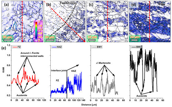
Figure 10.
KAM maps. (a) FZ, (b) fusion line between the FZ and HAZ, (c) BM1, (d) BM2, and (e) KAM profiles for all the analyzed zones (the KAM profiles were obtained following the red dashed arrow on each KAM map).
On the HAZ side, the KAM increments are produced by the α’-martensite formation, as demonstrated by the KAM profile in Figure 10e. In more distant areas, e.g., the BM1 zone, the heat transfer impact can still be observed with KAM values similar to the HAZ, as displayed in Figure 10c,e. The behavior changes in the BM2 zone where the KAM values increase considerably in the α’-martensite, as shown in Figure 10d,e. The KAM increments are associated with a high density of defects, such as statistically stored and GND dislocations, which are more affected by the high temperatures around the HAZ. On the FZ side, the high KAM values can also be associated with the shrinkage phenomena during the solidification that gives rise to high residual stresses.
Using X-ray diffraction, it is possible to calculate the dislocation density and the phase volume fraction considering the peak broadening and the integrated area of each diffracted peak. The phases volume fraction and the dislocation densities obtained with Equations (1) and (2) and the diffractograms in Figure 11a allow for the subsequent observations: (1) dislocations densities are higher in the BM than in the FZ; (2) α’-martensite and δ-ferrite are the phases with the highest dislocation density corroborating the plastic gradients with austenite; and (3) δ-ferrite in the FZ has a higher dislocation density than austenite after the welding process.
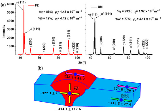
Figure 11.
(a) X-ray diffraction patterns from the FZ and the BM zones and (b) residual stresses in the weld seam (values are in MPa).
As mentioned before, the mechanical properties of weld seams can be affected by residual stresses originating during the liquid-to-solid shrinkage during solidification or from the thermal gradients with the HAZ. Figure 11b indicates the residual stresses in the FZ and the BM obtained by X-ray diffraction after the small sample was cut from the tube. So, the sample is free from macroscopic stresses imposed during tube fabrication. The blue dots show the measurement places either on the external surfaces or internally, after cutting. The values calculated suggest that the FZ withstands compression-type stresses in the middle zone and tension-type on the superior exterior surface. This is coherent with the weld seam shape, where the upper part is wider than the inferior because the melted material can flow easier in the upper part than in the inferior one, where the melted material is more constrained by the tube wall thickness. The same happens in the HAZ, where the tube resistance to shrinkage during the solidification of the melt pool in the FZ produces compression and tension-type stresses on the cross and superficial areas, respectively. This behavior has been reported by several researchers that also found significant tension-type residual stresses in the weld seam surface, then changed to compression type towards the FZ interior [52,53].
No doubt, welding is a complex manufacturing process where several phase transformations, microstructural changes, and stress states can be involved. Although the studied ASS suffered multiple changes across the weld seam and BM, its overall strength and ductility remain quite high from a mechanical point of view. However, other properties, such as corrosion resistance, should be evaluated to fully characterize its performance.
4. Conclusions
The study of the mechanical and microstructural heterogeneity on a weld seam applied in an ASS-304L tube through OM, EBSD, X-ray diffraction, hardness measurements, and tensile tests allowed drawing the following conclusions:
The GTAW welding process on an ASS resulted in a biphasic microstructure inside the FZ made up of δ-ferrite (~10%) and γ-austenite with different dendritic morphologies due to a favorable . Moreover, δ-ferrite created interconnected dislocation walls in the FZ, as illustrated by KAM analysis. This gave rise to strength improvements because of the δ-ferrite grain size (5.9 µm) smaller than austenite (253 µm) and the obstacles (interconnected dislocation walls) for the crack’s free propagation in the austenite large grains.
Thermal gradients produced grain growth from the fusion line to the BM with values ranging from 100 µm to 10 µm. It was also found higher dislocation density and smaller grain size in the α’-martensite ( = 4.11 × 10¹⁴ m−2) than in austenite ( = 1.92 × 10¹⁴ m−2). However, the mechanical properties between the HAZ and the BM only showed 30 MPa strength and 5% elongation differences.
Deformation maps demonstrated that the lowest strength and ductility in the FZ (ultimate tensile strength of 1100 MPa and maximum elongation of 45%) was associated with a strong localized strain allowing the plastic instability occurs earlier than in the HAZ (ultimate tensile strength of 1300 MPa and maximum elongation of 58%) and BM (ultimate tensile strength of 1330 MPa and maximum elongation of 63%), where the strain localized in multiple points delaying the plastic instability.
After all the microstructural, texture, and residual stress variations across the weld seam and the BM, from a mechanical point of view, the FZ is revealed as the weakest point of the weld seam. However, this zone reached a mechanical strength higher than 1 GPa with a homogeneous deformation zone of 0.4 true strain, which can be considered a good strength–ductility ratio. This performance was highly related to the heterogeneous structure in the FZ originated during the solidification process.
Author Contributions
Conceptualization, J.A.M.; methodology, J.A.M., E.D., M.A. and R.B.; software, J.A.M.; validation, R.B. and J.M.C.; formal analysis, J.A.M. and E.D.; investigation, J.A.M., V.T. and P.R.; resources, M.A., R.B. and J.M.C.; data curation, J.A.M., V.T. and P.R.; writing—original draft preparation, J.A.M. and J.M.C.; writing—review and editing, J.A.M., R.B. and J.M.C.; supervision, R.B. and J.M.C.; project administration, R.B. and J.M.C.; funding acquisition, M.A., R.B. and J.M.C. All authors have read and agreed to the published version of the manuscript.
Funding
This research received no external funding.
Data Availability Statement
Not applicable.
Acknowledgments
The authors thank Alexander Komissarov from National University of Science and Technology “MISIS” for providing the studied tubes.
Conflicts of Interest
The authors declare no conflict of interest.
References
- Mohan Kumar, S.; Siva Shanmugam, N. Effect of Heat Input and Weld Chemistry on Mechanical and Microstructural Aspects of Double Side Welded Austenitic Stainless Steel 321 Grade Using Tungsten Inert Gas Arc Welding Process. Materwiss. Werksttech. 2020, 51, 349–367. [Google Scholar] [CrossRef]
- Costanza, G.; Sili, A.; Tata, M.E. Weldability of Austenitic Stainless Steel by Metal Arc Welding with Different Shielding Gas. Procedia Struct. Integr. 2016, 2, 3508–3514. [Google Scholar] [CrossRef]
- Sirohi, S.; Pandey, C.; Goyal, A. Role of Heat-Treatment and Filler on Structure-Property Relationship of Dissimilar Welded Joint of P22 and F69 Steel. Fusion Eng. Des. 2020, 159, 111935. [Google Scholar] [CrossRef]
- Rathod, D.W. Chapter 4—Comprehensive Analysis of Gas Tungsten Arc Welding Technique for Ni-Base Weld Overlay. In Advanced Welding and Deforming; Paulo Davim, J., Gupta, K., Gupta, K., Paulo Davim, J., Eds.; Handbooks in Advanced Manufacturing; Elsevier: Amsterdam, The Netherlands, 2021; pp. 105–126. ISBN 978-0-12-822049-8. [Google Scholar]
- Smith, P. Chapter 6—Fabrication, Assembly, and Erection. In The Fundamentals of Piping Design; Smith, P., Ed.; Gulf Publishing Company: Houston, TX, USA, 2007; pp. 171–189. ISBN 978-1-933762-04-3. [Google Scholar]
- Komissarov, A.A.; Sokolov, P.Y.; Tikhonov, S.M.; Sidorova, E.P.; Mishnev, P.A.; Matrosov, M.Y.; Kuznetsov, D. V Production of Low-Carbon Steel Sheet for Oil-Industry Pipe. Steel Transl. 2018, 48, 748–753. [Google Scholar] [CrossRef]
- Chuaiphan, W.; Srijaroenpramong, L. Effect of Hydrogen in Argon Shielding Gas for Welding Stainless Steel Grade SUS 201 by GTA Welding Process. J. Adv. Join. Process. 2020, 1, 100016. [Google Scholar] [CrossRef]
- Zhu, Z.; Ma, X.; Wang, C.; Mi, G.; Zheng, S. The Metallurgical Behaviors and Crystallographic Characteristic on Macro Deformation Mechanism of 316 L Laser-MIG Hybrid Welded Joint. Mater. Des. 2020, 194, 108893. [Google Scholar] [CrossRef]
- Ogawa, T.; Koseki, T. Weldability of Newly Developed Austenitic Alloys for Cryogenic Service: Part 1—Up-to-Date Overview of Welding Technology. Weld. J. 1987, 66, 8–17. [Google Scholar]
- Padilha, A.F.; Rios, P.R. Decomposition of Austenite in Austenitic Stainless Steels. ISIJ Int. 2002, 42, 325–327. [Google Scholar] [CrossRef]
- Zhang, S.; Wang, P.; Li, D.; Li, Y. Investigation of the Evolution of Retained Austenite in Fe–13%Cr–4%Ni Martensitic Stainless Steel during Intercritical Tempering. Mater. Des. 2015, 84, 385–394. [Google Scholar] [CrossRef]
- Yin, Y.; Faulkner, R.; Starr, F. 5—Austenitic Steels and Alloys for Power Plants. In Structural Alloys for Power Plants; Shirzadi, A., Jackson, S., Eds.; Woodhead Publishing Series in Energy; Woodhead Publishing: Sawston, UK, 2014; pp. 105–152. ISBN 978-0-85709-238-0. [Google Scholar]
- Was, G.S.; Ukai, S. Chapter 8—Austenitic Stainless Steels. In Structural Alloys for Nuclear Energy Applications; Odette, G.R., Zinkle, S.J., Eds.; Elsevier: Boston, MA, USA, 2019; pp. 293–347. ISBN 978-0-12-397046-6. [Google Scholar]
- Michler, T. Austenitic Stainless Steels. In Reference Module in Materials Science and Materials Engineering; Elsevier: Amsterdam, The Netherlands, 2016; ISBN 978-0-12-803581-8. [Google Scholar]
- Tedmon, C.S.; Vermilyea, D.A.; Rosolowski, J.H. Intergranular Corrosion of Austenitic Stainless Steel. J. Electrochem. Soc. 1971, 118, 192. [Google Scholar] [CrossRef]
- Fregonese, M.; Idrissi, H.; Mazille, H.; Renaud, L.; Cetre, Y. Initiation and Propagation Steps in Pitting Corrosion of Austenitic Stainless Steels: Monitoring by Acoustic Emission. Corros. Sci. 2001, 43, 627–641. [Google Scholar] [CrossRef]
- Kain, V. 5—Stress Corrosion Cracking (SCC) in Stainless Steels. In Stress Corrosion Cracking; Raja, V.S., Shoji, T., Eds.; Woodhead Publishing Series in Metals and Surface Engineering; Woodhead Publishing: Sawston, UK, 2011; pp. 199–244. ISBN 978-1-84569-673-3. [Google Scholar]
- Böhner, A.; Niendorf, T.; Amberger, D.; Höppel, H.W.; Göken, M.; Maier, H.J. Martensitic Transformation in Ultrafine-Grained Stainless Steel AISI 304L Under Monotonic and Cyclic Loading. Metals 2012, 2, 56–64. [Google Scholar] [CrossRef]
- Hamada, A.S.; Karjalainen, L.P.; Surya, P.K.C.V.; Misra, R.D.K. Fatigue Behavior of Ultrafine-Grained and Coarse-Grained Cr–Ni Austenitic Stainless Steels. Mater. Sci. Eng. A 2011, 528, 3890–3896. [Google Scholar] [CrossRef]
- Lima, A.S.; Nascimento, A.M.; Abreu, H.F.G.; de Lima-Neto, P. Sensitization Evaluation of the Austenitic Stainless Steel AISI 304L, 316L, 321 and 347. J. Mater. Sci. 2005, 40, 139–144. [Google Scholar] [CrossRef]
- Muthupandi, V.; Bala Srinivasan, P.; Seshadri, S.K.; Sundaresan, S. Effect of Weld Metal Chemistry and Heat Input on the Structure and Properties of Duplex Stainless Steel Welds. Mater. Sci. Eng. A 2003, 358, 9–16. [Google Scholar] [CrossRef]
- Quitzke, C.; Schröder, C.; Mandel, M.; Krüger, L.; Volkova, O.; Wendler, M. Solidification of Plasma TIG-Welded N-Alloyed Austenitic CrMnNi Stainless Steel. Weld. World 2022, 66, 2217–2229. [Google Scholar] [CrossRef]
- Shankar, V.; Gill, T.P.S.; Mannan, S.L.; Sundaresan, S. Solidification Cracking in Austenitic Stainless Steel Welds. Sadhana 2003, 28, 359–382. [Google Scholar] [CrossRef]
- Igathinathane, C.; Pordesimo, L.O.; Columbus, E.P.; Batchelor, W.D.; Methuku, S.R. Shape Identification and Particles Size Distribution from Basic Shape Parameters Using ImageJ. Comput. Electron. Agric. 2008, 63, 168–182. [Google Scholar] [CrossRef]
- Bachmann, F.; Hielscher, R.; Schaeben, H. Texture Analysis with MTEX–Free and Open Source Software Toolbox. Solid State Phenom. 2010, 160, 63–68. [Google Scholar] [CrossRef]
- Muñoz, J.A.; Komissarov, A. Back Stress and Strength Contributions Evolution of a Heterogeneous Austenitic Stainless Steel Obtained after One Pass by Equal Channel Angular Sheet Extrusion (ECASE). Int. J. Adv. Manuf. Technol. 2020, 109, 607–617. [Google Scholar] [CrossRef]
- De, A.K.; Murdock, D.C.; Mataya, M.C.; Speer, J.G.; Matlock, D.K. Quantitative Measurement of Deformation-Induced Martensite in 304 Stainless Steel by X-Ray Diffraction. Scr. Mater. 2004, 50, 1445–1449. [Google Scholar] [CrossRef]
- Lutterotti, L.; Matthies, S.; Wenk, H.R. MAUD (Material Analysis Using Diffraction): A User Friendly Java Program for Rietveld Texture Analysis and More. In Proceedings of the Twelfth International Conference on Textures of Materials (ICOTOM-12), Montreal, QC, Canada, 9–13 August 1999; NRC Research Press: Ottawa, ON, Canada, 1999; p. 1599. [Google Scholar]
- Zhao, Y.H.; Sheng, H.W.; Lu, K. Microstructure Evolution and Thermal Properties in Nanocrystalline Fe during Mechanical Attrition. Acta Mater. 2001, 49, 365–375. [Google Scholar] [CrossRef]
- Ghani, A.F.A.; Ali, M.B.; Dharmalingam, S.; Mahmud, J. Digital Image Correlation (DIC) Technique in Measuring Strain Using Opensource Platform Ncorr. J. Adv. Res. Appl. Mech. 2016, 26, 10–21. [Google Scholar] [CrossRef]
- Ostovan, F.; Shafiei, E.; Toozandehjani, M.; Mohamed, I.F.; Soltani, M. On the Role of Molybdenum on the Microstructural, Mechanical and Corrosion Properties of the GTAW AISI 316 Stainless Steel Welds. J. Mater. Res. Technol. 2021, 13, 2115–2125. [Google Scholar] [CrossRef]
- Yazdian, N.; Mohammadpour, M.; Razavi, R.; Kovacevic, R. Hybrid Laser/Arc Welding of 304L Stainless Steel Tubes, Part 2–Effect of Filler Wires on Microstructure and Corrosion Behavior. Int. J. Press. Vessel. Pip. 2018, 163, 45–54. [Google Scholar] [CrossRef]
- Shen, Y.F.; Li, X.X.; Sun, X.; Wang, Y.D.; Zuo, L. Twinning and Martensite in a 304 Austenitic Stainless Steel. Mater. Sci. Eng. A 2012, 552, 514–522. [Google Scholar] [CrossRef]
- Suutala, N.; Takalo, T.; Moisio, T. The Relationship between Solidification and Microstructure in Austenitic and Austenitic-Ferritic Stainless Steel Welds. Metall. Trans. A 1979, 10, 512–514. [Google Scholar] [CrossRef]
- Lu, B.T.; Chen, Z.K.; Luo, J.L.; Patchett, B.M.; Xu, Z.H. Pitting and Stress Corrosion Cracking Behavior in Welded Austenitic Stainless Steel. Electrochim. Acta 2005, 50, 1391–1403. [Google Scholar] [CrossRef]
- Schramm, R.E.; Reed, R.P. Stacking Fault Energies of Seven Commercial Austenitic Stainless Steels. Metall. Trans. A 1975, 6, 1345. [Google Scholar] [CrossRef]
- Allain, S.; Chateau, J.-P.; Bouaziz, O. A Physical Model of the Twinning-Induced Plasticity Effect in a High Manganese Austenitic Steel. Mater. Sci. Eng. A 2004, 387–389, 143–147. [Google Scholar] [CrossRef]
- Muñoz, J.A.; Komissarov, A.; Avalos, M.; Bolmaro, R.E. Mechanical and Microstructural Behavior of a Heterogeneous Austenitic Stainless Steel Processed by Equal Channel Angular Sheet Extrusion (ECASE). Mater. Sci. Eng. A 2020, 792, 139779. [Google Scholar] [CrossRef]
- Muñoz, J.A.; Komissarov, A.; Mejía, I.; Hernández-Belmontes, H.; Cabrera, J.-M. Characterization of the Gas Tungsten Arc Welding (GTAW) Joint of Armco Iron Nanostructured by Equal-Channel Angular Pressing (ECAP). J. Mater. Process. Technol. 2021, 288, 116902. [Google Scholar] [CrossRef]
- Muñoz, J.A.; Cobos, O.F.H.; M’Doihoma, R.; Avalos, M.; Bolmaro, R.E. Inducing Heterogeneity in an Austenitic Stainless Steel by Equal Channel Angular Sheet Extrusion (ECASE). J. Mater. Res. Technol. 2019, 8, 2473–2479. [Google Scholar] [CrossRef]
- Nye, J.F. Some Geometrical Relations in Dislocated Crystals. Acta Metall. 1953, 1, 153–162. [Google Scholar] [CrossRef]
- Muñoz, J.A.; Avalos, M.; Schell, N.; Brokmeier, H.G.; Bolmaro, R.E. Comparison of a Low Carbon Steel Processed by Cold Rolling (CR) and Asymmetrical Rolling (ASR): Heterogeneity in Strain Path, Texture, Microstructure and Mechanical Properties. J. Manuf. Process. 2021, 64, 557–575. [Google Scholar] [CrossRef]
- Muñoz, J.A. Geometrically Necessary Dislocations (GNDs) in Iron Processed by Equal Channel Angular Pressing (ECAP). Mater. Lett. 2019, 238, 42–45. [Google Scholar] [CrossRef]
- Muñoz, J.A.; Chand, M.; Signorelli, J.W.; Calvo, J.; Cabrera, J.M. Strengthening of Duplex Stainless Steel Processed by Equal Channel Angular Pressing (ECAP). Int. J. Adv. Manuf. Technol. 2022, 123, 2261–2278. [Google Scholar] [CrossRef]
- Ramazani, A.; Mukherjee, K.; Schwedt, A.; Goravanchi, P.; Prahl, U.; Bleck, W. Quantification of the Effect of Transformation-Induced Geometrically Necessary Dislocations on the Flow-Curve Modelling of Dual-Phase Steels. Int. J. Plast. 2013, 43, 128–152. [Google Scholar] [CrossRef]
- Kumar, S.S.S.; Vasanth, M.; Singh, V.; Ghosal, P.; Raghu, T. An Investigation of Microstructural Evolution in 304L Austenitic Stainless Steel Warm Deformed by Cyclic Channel Die Compression. J. Alloys Compd. 2017, 699, 1036–1048. [Google Scholar] [CrossRef]
- Li, J.; Fang, C.; Liu, Y.; Huang, Z.; Wang, S.; Mao, Q.; Li, Y. Deformation Mechanisms of 304L Stainless Steel with Heterogeneous Lamella Structure. Mater. Sci. Eng. A 2019, 742, 409–413. [Google Scholar] [CrossRef]
- Considère, A. Memoire Sur l’emploi Du Fer et de l’acier Dans Les Constructions. Ann. Ponts Chaussées Sem. 1885, 9, 574–775. [Google Scholar]
- Romero-Resendiz, L.; El-Tahawy, M.; Zhang, T.; Rossi, M.C.; Marulanda-Cardona, D.M.; Yang, T.; Amigó-Borrás, V.; Huang, Y.; Mirzadeh, H.; Beyerlein, I.J.; et al. Heterostructured Stainless Steel: Properties, Current Trends, and Future Perspectives. Mater. Sci. Eng. R Rep. 2022, 150, 100691. [Google Scholar] [CrossRef]
- Wright, S.I.; Nowell, M.M.; Field, D.P. A Review of Strain Analysis Using Electron Backscatter Diffraction. Microsc. Microanal. 2011, 17, 316–329. [Google Scholar] [CrossRef] [PubMed]
- García-García, V.; Mejía, I.; Hernández-Belmontes, H.; Reyes-Calderón, F.; Benito, J.A.; Cabrera, J.M. Computational Simulation of Thermo-Mechanical Field and Fluid Flow and Their Effect on the Solidification Process in TWIP Steel Welds. J. Manuf. Process. 2022, 84, 100–120. [Google Scholar] [CrossRef]
- Ishigami, A.; Roy, M.J.; Walsh, J.N.; Withers, P.J. The Effect of the Weld Fusion Zone Shape on Residual Stress in Submerged Arc Welding. Int. J. Adv. Manuf. Technol. 2017, 90, 3451–3464. [Google Scholar] [CrossRef]
- Ganesh, K.C.; Vasudevan, M.; Balasubramanian, K.R.; Chandrasekhar, N.; Mahadevan, S.; Vasantharaja, P.; Jayakumar, T. Modeling, Prediction and Validation of Thermal Cycles, Residual Stresses and Distortion in Type 316 LN Stainless Steel Weld Joint Made by TIG Welding Process. Procedia Eng. 2014, 86, 767–774. [Google Scholar] [CrossRef]


Disclaimer/Publisher’s Note: The statements, opinions and data contained in all publications are solely those of the individual author(s) and contributor(s) and not of MDPI and/or the editor(s). MDPI and/or the editor(s) disclaim responsibility for any injury to people or property resulting from any ideas, methods, instructions or products referred to in the content. |
© 2023 by the authors. Licensee MDPI, Basel, Switzerland. This article is an open access article distributed under the terms and conditions of the Creative Commons Attribution (CC BY) license (https://creativecommons.org/licenses/by/4.0/).