Article

Effects of Nickel Plating on Interference Fit between Medium Carbon Steel and Copper–Zinc Alloy Parts

1
Department of Machine Design, Faculty of Mechanical Engineering, Ho Chi Minh City University of Technology (HCMUT), 268 Ly Thuong Kiet Street, District 10, Ho Chi Minh City 700000, Vietnam
2
Vietnam National University Ho Chi Minh City, Linh Trung Ward, Thu Duc City, Ho Chi Minh City 700000, Vietnam
*
Author to whom correspondence should be addressed.
Metals 2023, 13(2), 247; https://doi.org/10.3390/met13020247
Submission received: 30 December 2022 / Revised: 24 January 2023 / Accepted: 24 January 2023 / Published: 28 January 2023
(This article belongs to the Section Welding and Joining)

Abstract

:
Studies on load capacity enhancement for an interference fit mainly focused on the essential coupling material pair of steel–steel parts. With more complex requirements in technical assemblies, more notable cases of material pairs are applied in interference fits. Hence, it is crucial to highlight the variations across-coupling scenarios in order to identify a workable approach for load capacity augmentation. The goal of this study is to examine how nickel plating affects the interference fit between steel and brass assembly parts. The experiments in this research focus on comparing the load capacity of plated and non-plated specimens by evaluating the extraction force on a compression machine. The fit parameters are measured with a coordinate measuring machine and contact surface profiler. Some microscopic observations are made to confirm the phenomena of this coupling case. The axial extraction tests determined that the plated fits show an increase in axial force limits of around 20% in comparison with the non-plated ones. There are also some significant improvements in the plated shaft surface properties, which reduce the physical adhesions between the shaft and hub. These results confirm the possibility of reusing the plated assembly parts, which gives highly economic and environmental advantages.

1. Introduction

Interference fits are high-efficiency and reliable connections between machine parts and mechanisms. There are multiple kinds depending on the geometries and assembly methods. The most popular ones have cylinder-shaped interfaces, whose assembly methods are either by press fitting or shrink fitting [1].
The joining procedure of interference fits is somewhat akin to an elastic deformation process—based on the diameter differential of joining parts. Textbooks portray this contrast level as the interference value, which is the main factor to consider among the others that affect interference-fit characteristics [2,3].
Along with the evolution of interference-fit calculating and designing theories, researchers have developed numerous empirical analyses focusing on load capacity enhancement. The primary considerations are the contact surface characteristics and the external effects, such as temperature or physical impacts.
In recent decades, some relevant studies have tested the above viewpoints step-by-step and obtained great results. Researchers have found close connections between fitting parameters and load capacity. The better the surface quality, the higher the fit strength [4,5,6,7]. A series of practical studies confirmed the significance of temperature and physical impacts on interference-fit characteristics. Through strain aging, the load capacity sharply increases when soaking the fits between the highly finished steel and stainless-steel parts at 300 °C for three hours [8,9]. Another study found that burnishing greatly increases surface hardness owing to asperities flattening, generating a favorable environment for the generation of residual interface stresses, and increasing load capacity by five times over non-burnished specimens [9,10].
Here, it is easy to see an interesting pattern. If the surface treatment solutions effectively solve other mechanical contact problems, they probably have the same effects in interference-fit applications. For this reason, studies started to consider the effectiveness of plating layers in enhancing the interference-fit load capacity.
Plating is a traditional surface treatment method with an archaic story of existence and development, from ancient jewelry in 2000 BC to highly complex machine parts in the weapon systems used in World War II. Today, their applications are widespread in manufacturing microchips, semiconductors, and aerospace technologies. The evolution of plating has created multiple new technologies, from filling basic human needs to answering the most complicated technical problems. Nickel plating is one of them. As its originals, nickel plating helps enhance surface properties and hardness, providing better product finishing. At contact interfaces, nickel plating helps increase surface wear resistance and corrosion resistance [11].
When applied in interference fits, the plated nickel layer contributes to the influences of heat treatment processes. A combination of nickel plating and heat treating at 500 °C for 7 h provides an axial force limitation that is three times as great as in usual cases [12]. Researchers also experimented with combining different plating materials to take advantage of their plating properties. With nickel plating’s concave filling ability and chromium plating’s strong bonding strength, researchers combined nickel and chromium as a sub-layer and a primary plating layer, resulting in a roughly 75% increase in load capacity [13].
Adding layers of materials between contact surfaces can be extended to another researchable direction, in which these layers are adhesive materials or act as adhesive films. They could be metallic or non-metallic. There are studies on applying thread-locking agents to increase the surface contact area by forming linkages between the bindings and the base materials. The empirical results showed that the actual contact area could be up to 100% compared with 25–30% of the traditional cases, corresponding to the enhancement of the load capacity from 10 to 20% [14]. In the case of metallic adhesives, it is usually a plating material layer with a lower recrystallization temperature than the substrate. After plating and assembling the parts, the joints go through various forms of stimulation to achieve the recrystallization temperature of the plating material. At this time, stronger bonds between the plating layer and the substrate form, raising the load capacity to three times greater than regular fits [15].
The current research status presented above inspires the objectives of this paper. Firstly, regarding the research materials, existing analyses only focused on the case of steel–steel interference fits [4,5,8,10,12,13]. Notwithstanding, the use of this fit is becoming more common in other coupling material applications. Worm gear transmission, in which a copper alloy rim attaches to a carbon steel hub, is one example. Additionally, because some materials are prone to temperature stress or inefficiency when being heat treated, the thermal or physical techniques employed for heat treatment may not be appropriate in some circumstances [8,10,12]. Another significant gap in this research problem is that it has not yet brought high applicability in calculating and designing interference-fit processes. The current results consider only a specific case and barely show the relationship between experimental and theoretical factors that directly affect the load capacity of the interference fit [4,5,12] (Table 1).
In terms of intuitive parameters, such as the coefficient of friction (CoF), these specific relationships still need to be made available, and the calculation is mainly based on some general standards. Many studies have made great efforts to evaluate the CoF in interference fits and give incredibly positive signals with acceptable measurement accuracies, which could help design and calculate interference fits [16,17].
The purpose of this research is to investigate the effects of nickel plating on the surface properties and load capacities of the interference fit between medium carbon steel and copper–zinc alloy (brass) components. The axial load limit and the CoF value are the main aspects, reflecting the load capacity and the behaviors of the fit surfaces.
This study specifically addressed and defined the following problems:
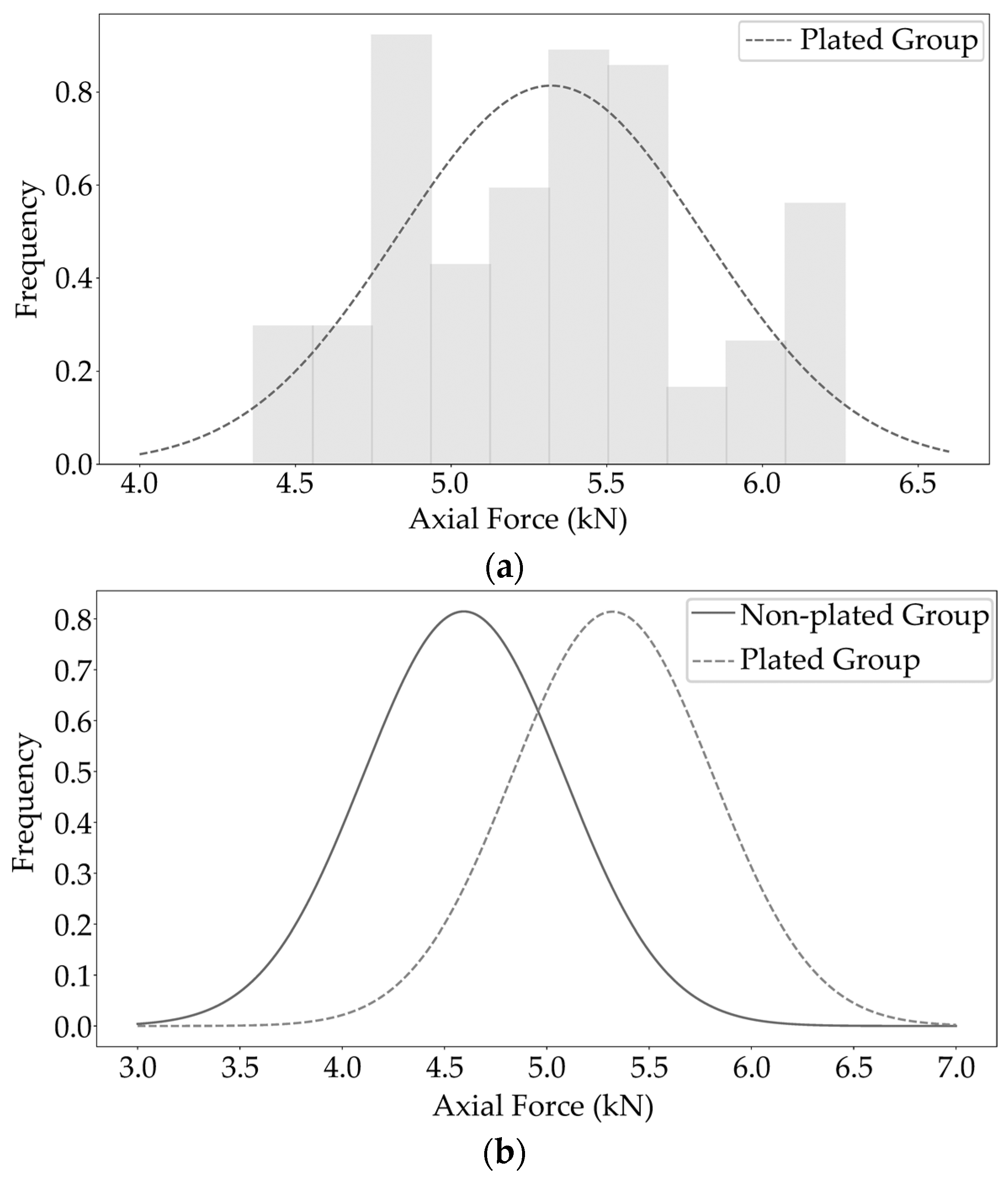
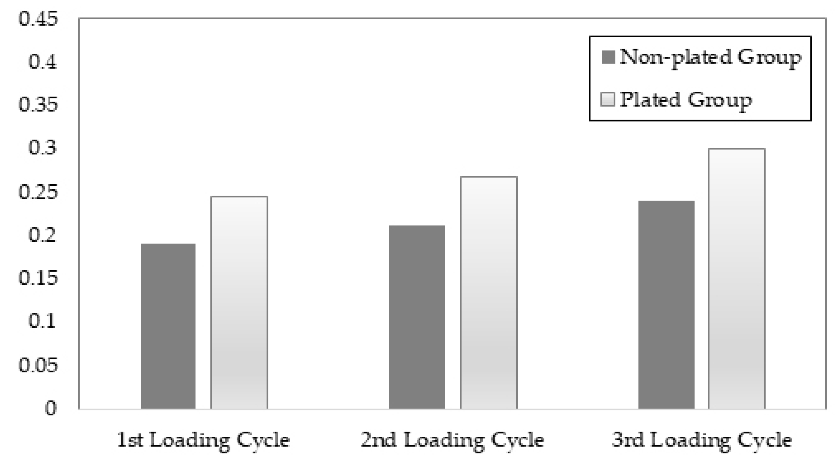
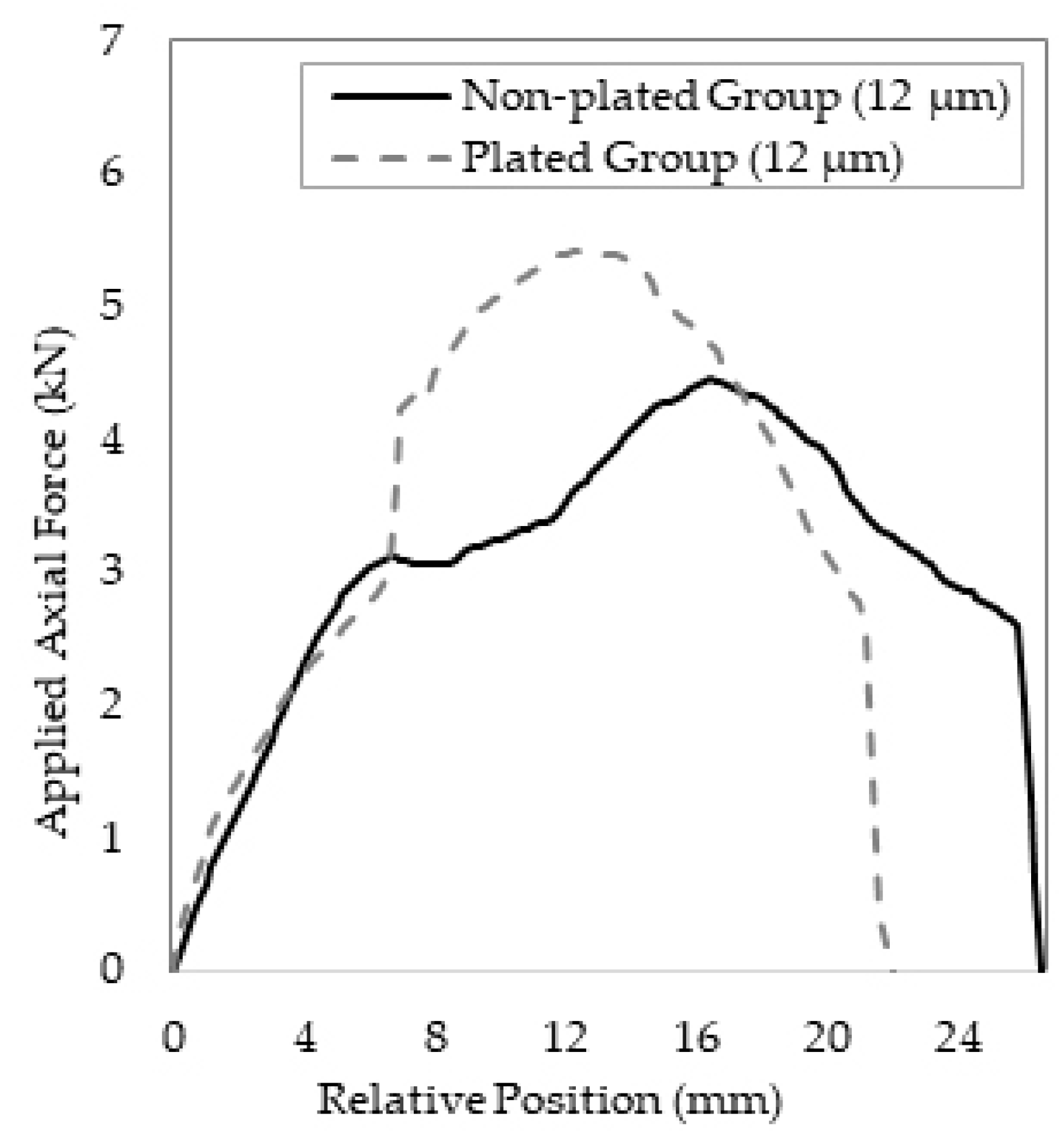
  • The increase in load capacity and CoF value of steel–brass interference fits by up to 20% with the application of nickel plating;
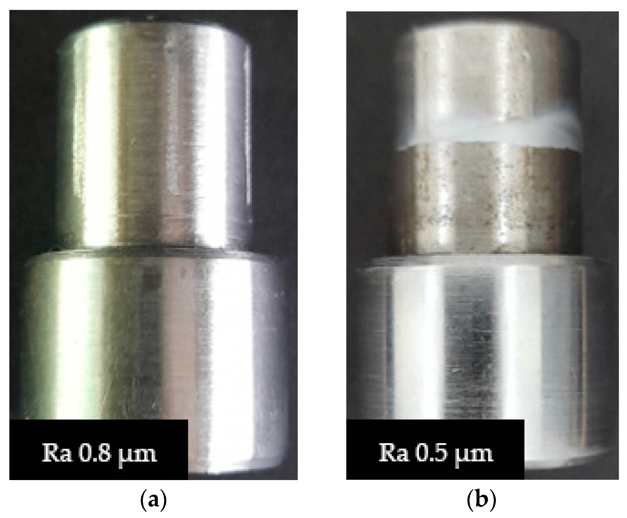
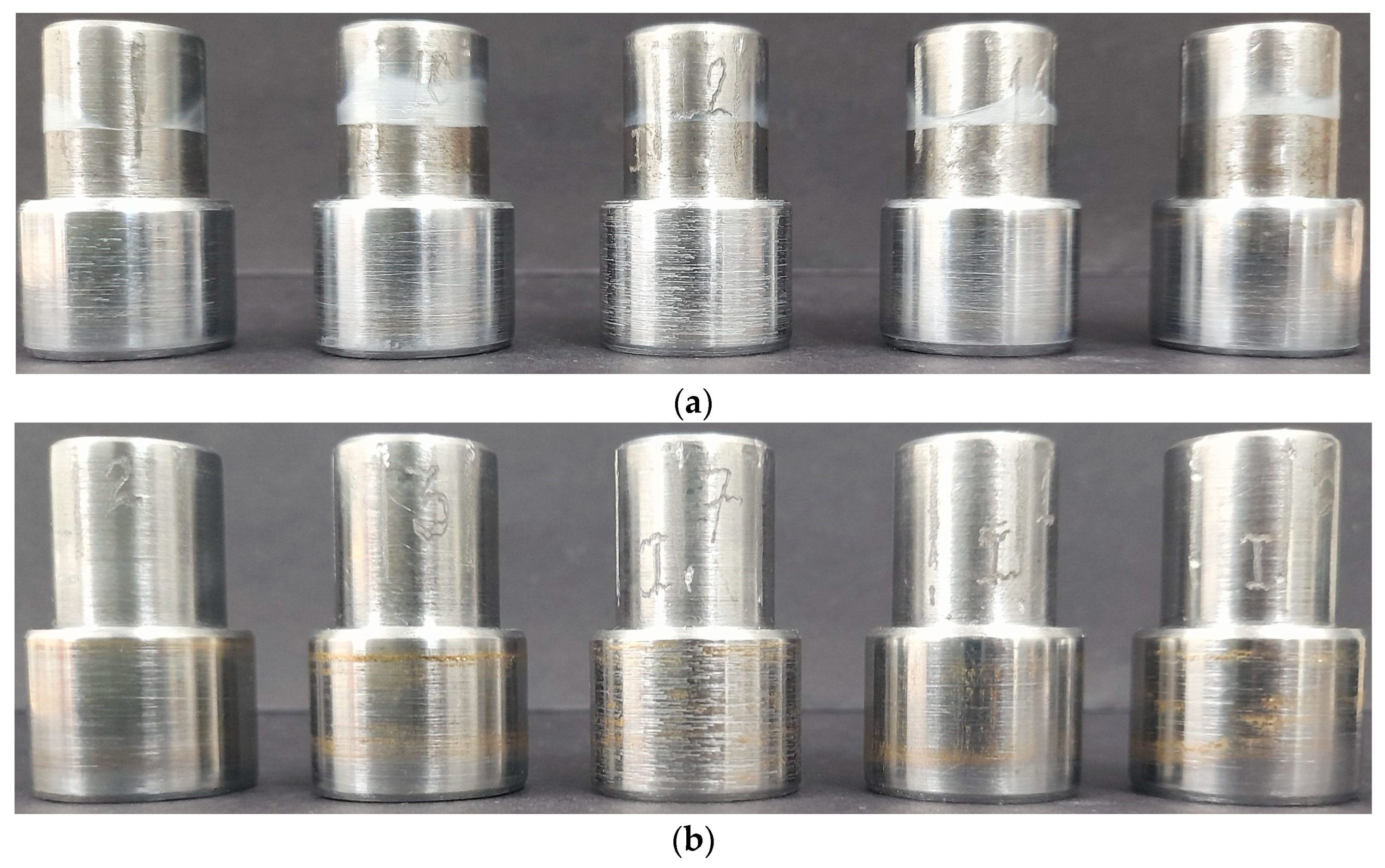
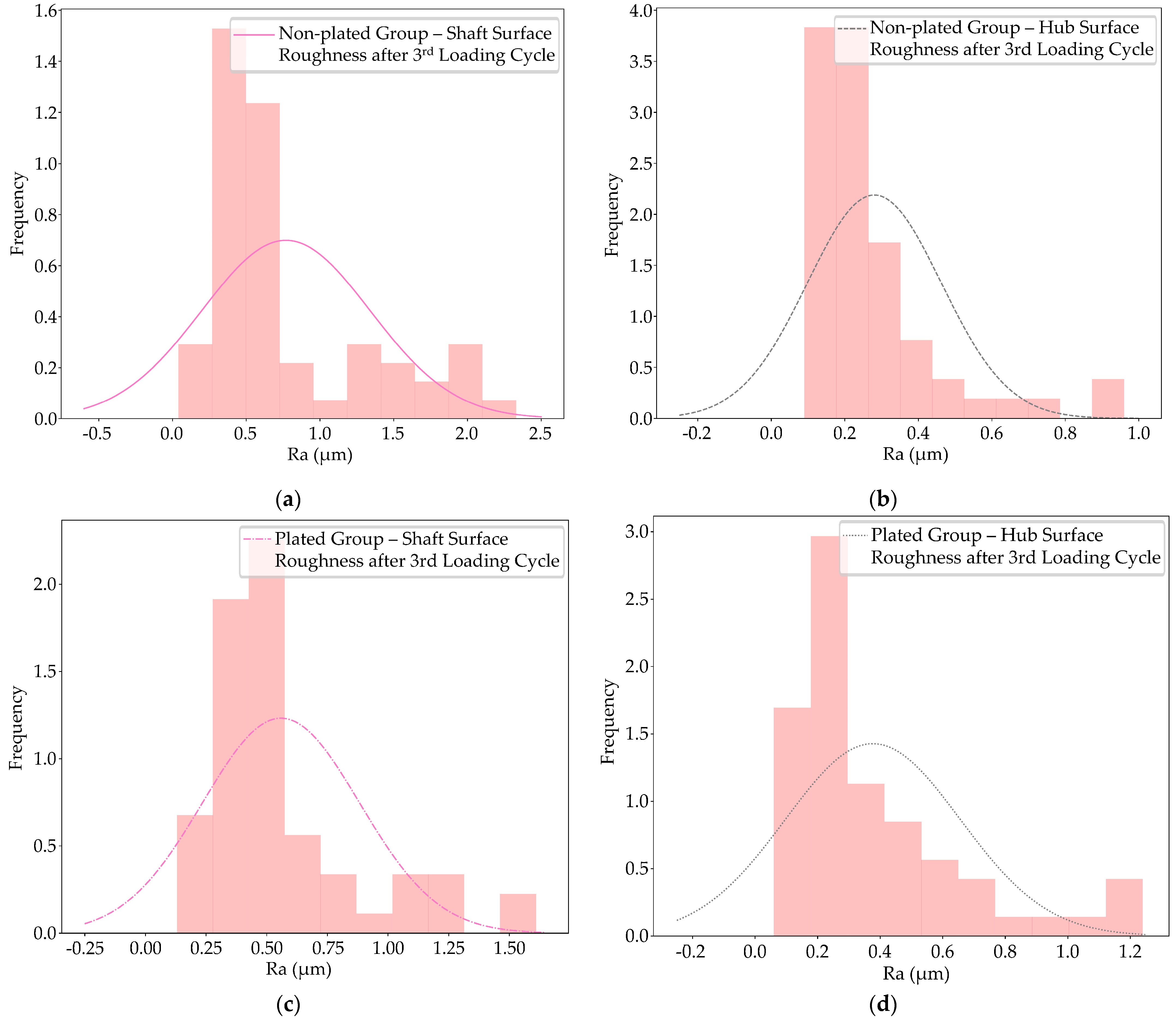
  • The differences in surface characteristics between non-plated and plated specimens, especially the identification of the physical adhesions phenomenon;
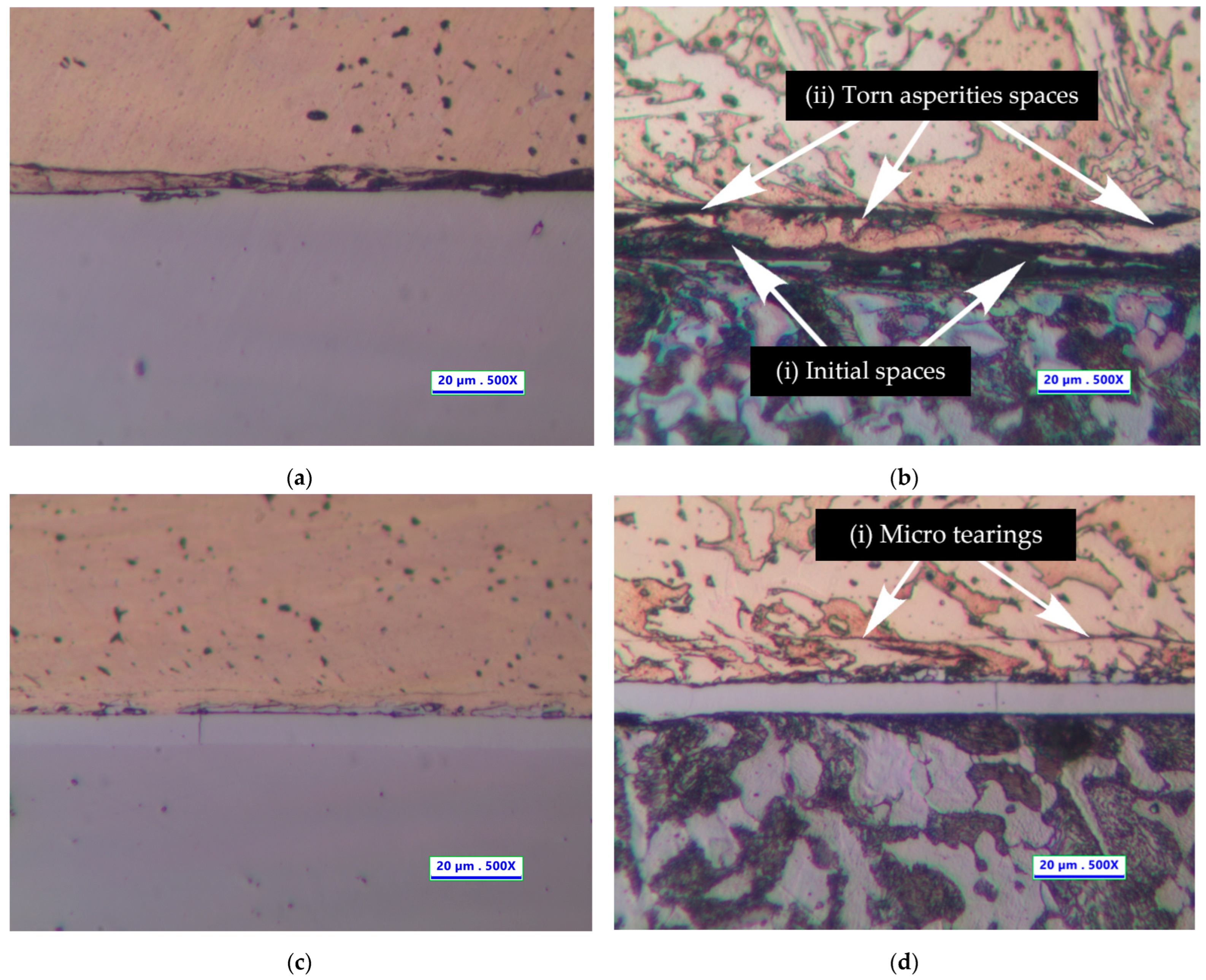
  • The microscopic observations at the contact interface.

2. Materials and Methods

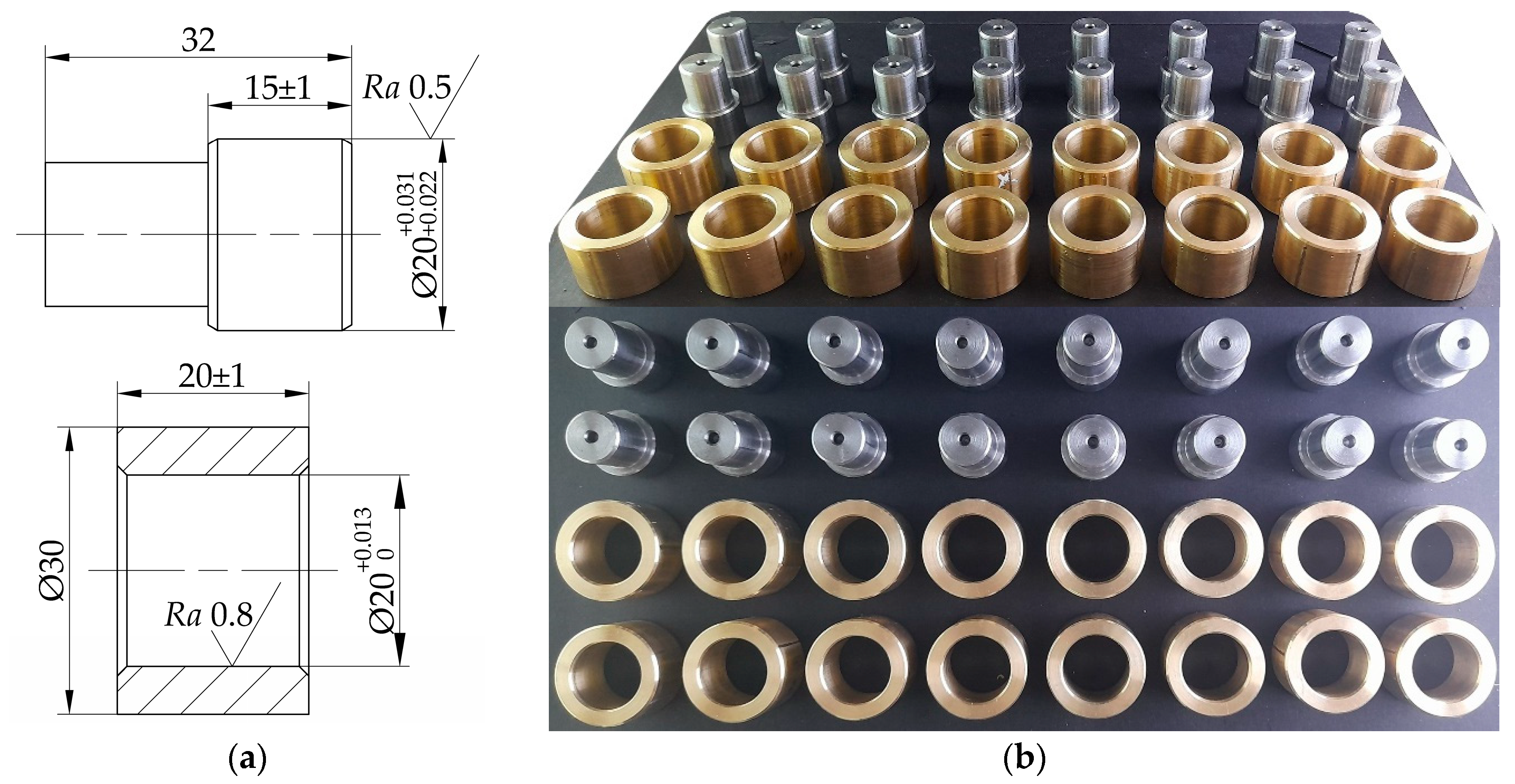
2.1. Coupling Parameters and Materials

This study discusses cylinder-shaped interference fits due to their widespread application. Following the archetypal research [5,6,8,10,12], this study concentrates on the fit’s nominal diameter df of 20 mm, with strict machining tolerances and other interference-fit factors (Figure 1). In Figure 1b, the upper figure is the front view and the lower figure is the top view of the selected specimens.
The analyzed objects in this study included medium carbon steel shafts and copper–zinc alloy hubs with material grades of C45 (steel) [18] and C2680 (brass) [19]. The material properties, such as Poisson’s ratio ν, Young’s modulus E, and yield strength σy, are as follows:
  • C45 Steel: νs = 0.3; Es = 210 GPa; σys = 360 MPa.
  • C2680 Brass: νh = 0.34; Eh = 112 GPa; σyh = 240 MPa.
Initially, 30 pairs of shafts and hubs were made. Then, by their differences in diameter value, we chose 16 pairs of shaft–hub (steel–brass) specimens and divided them into two groups of interference fits and clearance fits. The interference-fit group has a mean interference value of around 15 μm, while the clearance fits group has a mean clearance value of roughly 2 μm.
Each sample group consists of eight pairs of specimens (eight shafts and eight hubs). The shaft specimens in the clearance-fit group were nickel-plated and ground until their nominal diameter was approximately about the value of their references in the interference-fit group (around 15 μm). To ensure the equivalences in tolerance field between the non-plated and plated samples and to achieve trustworthy axial force testing results, each pair of plated samples group were inspected after every plating and grinding step. Then, the specimens were tested on a compression machine, followed by the analysis of the nickel-plated layer on the load capacity.

2.2. Nickel Plating Application

Regarding the clearance-fit group, electroplating was used to add a nickel layer on the shaft surfaces, with a thickness tp of about 150–200 μm, followed by grinding processes to reduce the shaft diameters until they reached the average diameter of the interference-fit group. There were clear distinctions in the shaft surfaces between the testing stages (Figure 2).
In this study, multiple-layer plating is the rational option to limit residual stresses in the nickel-plating process, which might lead to microcracks in the plated layer and a loss in the work capability of the plated components. The plating methods also used selective plating techniques, which cover the non-working surfaces with tiny layers of non-conductive paint. These treatments guaranteed that the plated material appeared exclusively on the working surfaces, reducing the possibility of micro defects. Before plating, the substrate surfaces were prepared by electrocleaning in alkaline solution to remove all the soils and other contaminants.
This research particularly analyzed the hard nickel-plating process, of which the main composition of the electrolytic bath was 180 g/L nickel sulphate (NiSO4·6H2O), with 25 g/L ammonium chloride (NH4Cl) as an additive and 30 g/L boric acid (H3BO3) as the buffer in controlling the pH level. The anodes used in the electroplating process were electrolytic nickel strips with a current density of 4 A/dm2, and the plating temperature was around 40–60 °C then stabilized at about 55 °C.
The multiple-layer plating procedure included three separate plating processes, each about 65 minutes long. After each process, the plated objects and the electrolyte solution needed a thorough cleaning and filtering. The results of this complex procedure were three nickel-plated layers stacking on each other. The overall plated material thickness ranged from 150 to 200 μm.
Then, the initial plated layers would be reduced by grinding processes to reach the desired interference values. The processing parameters must be carefully controlled at these grinding states to minimize their effects on the final plated layer.

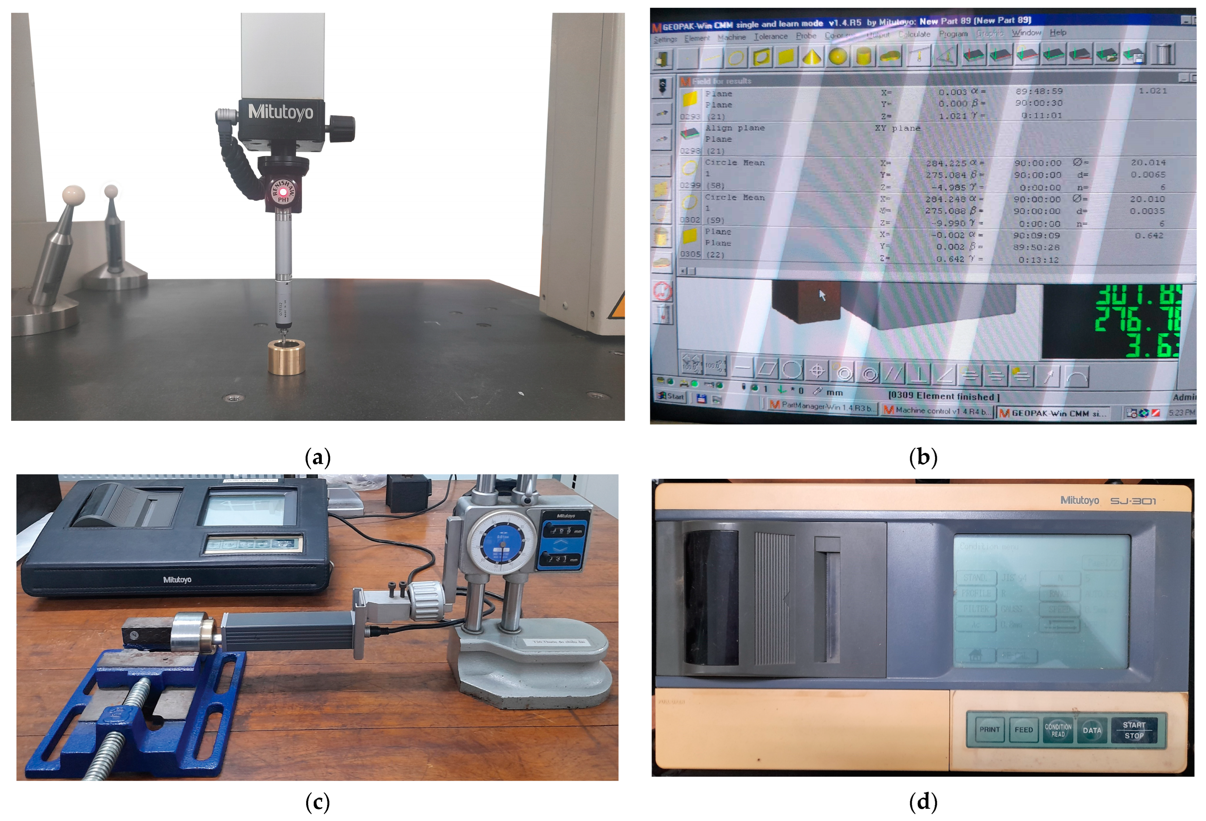
2.3. Dimensional Aspects Measurement

Theoretically, the interference value is the difference between the nominal diameters and depends on the surface roughness value. As stated, this interference value has an undeniable role in the assembly characteristics, so it is necessary to use highly accurate measuring methods. This study used coordinate measuring and contacting surface profiling methods to investigate the diameter and surface roughness values (Figure 3).
The measuring processes started with a diameter evaluation on the Mitutoyo Beyond Apex 504 (Mitutoyo Corporation, Sakado, Japan) (Figure 3a,b) and were carried out at six points on three equally spaced cross-sections. The surface roughness examinations were performed on six ruling lines and were repeated twice on each line to make sure the fit’s length was all covered. Specifically, the arithmetic average roughness (Ra) levels were considered under DIN EN ISO 4288 [20] with Gaussian filter and a cut-off wavelength λc = 0.8 mm. The roughness evaluation was made with the Mitutoyo SJ-301 surface profiler (Mitutoyo Corporation, Sakado, Japan) (Figure 3c,d).
All the measures were averaged. The results partially guaranteed the initial requirements in Figure 1a. The interference values ranged from 9 to 31 μm, and the surface roughness was within Ra 0.5–Ra 0.8.

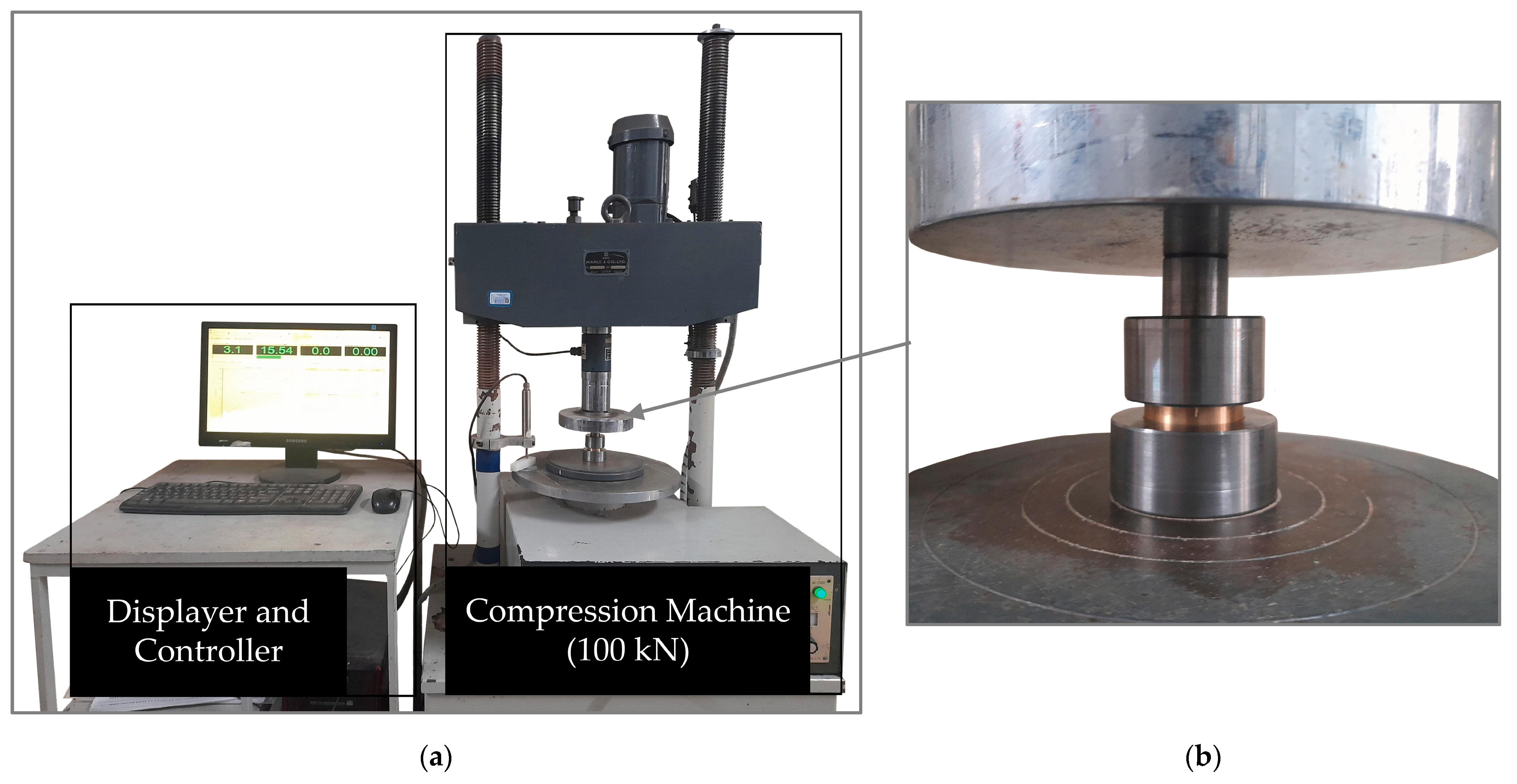
2.4. Axial Extraction Test

The axial pressing method was used to join and dismantle the specimens, in which the parts were held into place through a set of fixtures [21]. The surfaces on the assembly parts, the fixtures, and the pressing tool were cleaned with acetone before testing.
The machine used in this axial extraction test is the MARUI testing system MIS-225-1-16 (MARUI & Co., Ltd., Osaka, Japan), which allows axial loading with a 100 kN maximum value (as shown in Figure 4). Based on this testing equipment and the standardized procedures in determining coefficient of friction through static friction limits [16,22], the axial extraction test in this research was executed.

2.5. Coefficient of Friction Evaluating

The load capacity of a fit is the primary feature representing the level of technical requirements for designing and calculating, which is also reflected by the contact pressure generated at the interface—p. Here, a common question of most related studies exists: How to evaluate the load capacity of an interference fit.
Indeed, it is a challenge to directly obtain the interface pressure value. Even if the process is achievable through numerical simulating methods, the analyzed results are often inaccurate [16,23]. As a practical solution, researchers often consider this problem indirectly through the axial holding force Fa or the holding torque Th [9], or sometimes, in complex cases, both of them (a combination of Fa and Th).
The following formula expresses the axial holding force Fa [3,17,21]:
F a = δ π l μ s 1 E s ( r f 2 + r i 2 r f 2 r i 2 ν s ) + 1 E h ( r o 2 + r f 2 r o 2 r f 2 + ν h )
There are two main groups of parameters:
  • The constants—whose values are almost unchanged during joining and dismantling processes. They include the following: l is the contact length; Es and Eh are the Young’s modulus of the shaft and hub material; νs and νh are the Poisson ratio of the shaft and hub material; rf, ri, and ro are the nominal radius, the shaft’s inner radius, and the hub’s outer radius, respectively.
  • The variables—which could have considerable changes during joining and dismantling processes. They include the following: δ is the actual interference value of the fit; μs is the static CoF.
Usually, when evaluating the actual interference δ, studies rely on the ratio of the actual measured mean interference value δm to the nominal diameter df, known as the relative interference value δm/df [7,21,24]. Specifically, in the case of a carbon steel shaft and a copper–zinc alloy hub, the equations are as follows [21]:
  • δm/df < 2.25‰:
δ = δ m [ 1.1...2.1 ] ( R a s + R a h )
  • δm/df ≥ 2.25‰:
δ = δ m [ 1.1...2.1 ] ( R a s + R a h ) L p
where Ras and Rah are the arithmetical mean roughness values of shaft and hub specimens; Lp is the interference loss value due to plastic deformation.
Because of the relationship between the CoF and other surface characteristics, it is hard to find the exact CoF value. To complete this task, researchers conventionally use some empirical analysis methods. They could be full models of interference-fit cases or some simplified specimens having their surfaces interact with each other under high pressure. The goal of these experimental analyses is to find the load limitation. Then, along with the input parameters of the joint, it is possible to transform the variables in Equation (1) to achieve the relevant CoF [16,17]. Regarding the case of an interference fit only subjected to axial load Fa, assuming its relative interference being less than 2.25%, Equation (1) could be transformed as follows:
μ = F a δ m [ 1.1...2.1 ] ( R a s + R a h ) [ A ]
where:
[ A ] = 1 E s ( r f 2 + r i 2 r f 2 r i 2 ν s ) + 1 E h ( r o 2 + r f 2 r o 2 r f 2 + ν h ) π l
[A] can be called the assembling coefficient—a group of constants representing the fit’s characteristics.

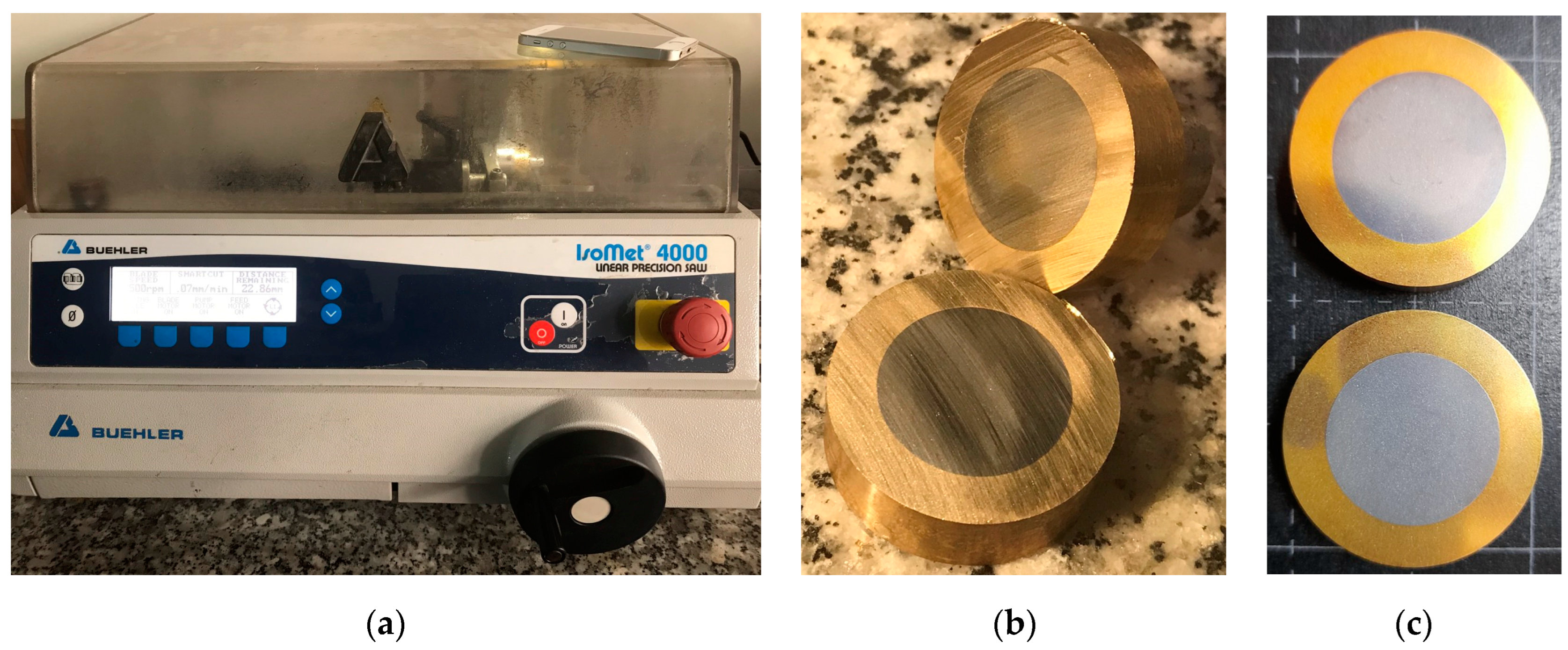
2.6. Microscopic Observation

The connected fits were cut with the Buehler IsoMet 4000 linear precision saw (Buehler Ltd., Lake Bluff, IL, USA) (Figure 5a). Using this device and carefully setting the cutting parameters made it possible to ensure no severe impact on the specimens, especially at the interface.
Then, the cut samples were ground, polished, etched (Figure 5c), and observed using the Buehler ViewMet inverted laboratory microscope (Buehler Ltd., Lake Bluff, IL, USA). Specifically, the etching procedure was carried out by swab etching method in 25 s with Carapella’s etchant, whose compositions include 5 g of iron chloride (FeCl3), 2 mL of hydrochloric acid (HCl), and 100 mL of ethanol. Then, the observations were carried out at four locations along the interface, evenly spaced at around 90° from one another.

3. Results and Discussion

After three loading cycles, the experimental results confirmed the effects of nickel plating in enhancing the load capacity of steel–brass interference fits.
Under the same experimental conditions, the group of plated shaft specimens showed remarkably higher axial force limitations. Regarding the same mean interference value δm = 12 μm, the load capacity of the plated group increased from 10 to 20% in comparison with the non-plated group (Figure 6).
The results were statistically analyzed to determine the expected value and standard deviation (Figure 7a). The distribution plots show that there is a considerable enhancement in the mean load capacity between the plated and non-plated groups (Figure 7b).
The above differences in axial force output can be considered as the changes in CoF value in each case, which depends on the actual interference value and the surface characteristics. Between plated and non-plated fits, after three cycles of joining and disassembling, the CoF values vary by approximately 20% (Table 2).
The mean CoF values between the non-plated and plated sample group gradually increase, while the mean interference values decrease after each loading cycle, which can be explained by the hardening of the surface asperities or strain aging on the hub surface. These effects also show a negative trend for CoF changes. The elastoplastic deformation of the asperities cancels out the stresses at the fit interface, which slowly reduces the load-enhancing effect of the nickel layer. The difference between the non-plated and plated group drops from 22.5% (between 0.19 and 0.244) at the first loading cycle to 20% (between 0.24 and 0.30) after the third time (as shown in Figure 8). This result is a warning for further studies into the sustainability of mechanical assembly parts.
The increase in value of the CoF compound can also be defined through the surface characteristics. After the first assembly, there were no physical adhesions on the plated shaft surfaces (Figure 9a). This phenomenon helps reduce the surface damage and lower the flattening of asperities on the brass hub.
Then, the average measured values and their standard deviations were used to determine the probability distribution curves (Figure 10). The analyzed results show a good similarity between the non-plated and plated specimens groups.
The nickel layer also helped increase the physical properties of the surface. After the first joining and disassembling process, the physical adhesions occurred on the non-plated shaft surface, which led to a slight increase in the surface roughness value (Figure 11a). In contrast, there was nearly nothing similar on the nickel-plated shafts (Figure 11b).
Despite their surface roughness result correlations, the plated specimens showed strong evidence of workability enhancement, shown in the microscopic images at the interface (Figure 12).
The microscopic images confirmed that the nickel electrodepositing procedure gave out good results. There were no microcracks in the plated material, which ensured the properties of the plating layer.
In the non-plated sample, there were many gaps between the two contact surfaces (Figure 12b). They included: (i) the initial spaces from the diameter differential and (ii) the generated spaces from the asperities tearing on the hub. These observations can give a solid explanation for the physical adhesion phenomena of the non-plated group.
In the plated sample, the plated material filled most of the asperities on the shaft, resulting in better contact surfaces. This phenomenon can be explained by the increase in asperities flattening while reducing the material tearing on the inferior surface (Figure 12d), which increases the interface pressure and enhances the fit’s load capacity.
The reduction in physical adhesion phenomena create a new study field in the maintenance of interference-fitted mechanisms. Considering common types of machinery that have worm gear transmission, there are interference fits between the steel worm gear hub and brass worm gear rim. When the rim goes to a failure state, technicians usually replace it or must replace the whole driving mechanism, which is costly in some complex transmission cases. In addition, we also replace in the case of sliding bearings, where the shaft is stationary and the working face of the sliding bearing is the outer surface. Then, the joint between the shaft and the inner surface of the sliding bearing has an interference fit.
This research confirms that in the case of an interference fit between steel and brass parts, with the help of hard nickel plating, the reusing of the inner assembled parts is completely practical.
From the obtained results and the proposed procedures, new studies can be performed to analyze the effects of other plating (or coating) technologies on interference-fit load capacity, such as physical vapor deposition (PVD) or chemical vapor deposition (CVD). These coating methods have the ability to apply extremely thin layers of materials on the substrate, which can optimize the effects of enhancing the CoF between interference-fitted parts.

4. Conclusions

This paper successfully finished an experimental analysis that evaluated the effects of nickel plating on enhancing the load capacity of interference fits between steel and brass specimens. Under the same interference level, the axial force testing showed an enhancement of a maximum of 20% in the load capacity between plated and non-plated fits. Here, the results significantly differed from the previous studies of steel–steel interference fits, which showed an increase of 75% [13]. This study also evaluated the CoF values in these plated cases of steel–brass interference fits, which increased in around 20% of non-plated cases.
Our microscopic observations ensure this conclusion. There are nearly no physical adhesions on the plated shaft surfaces, which could adversely affect assembly parts. The microscopic images once again confirm the above analyses. There is nearly no tearing of the brass asperities, increasing the contact area between assembly parts and the interface pressure.
These results settle some disputes regarding the load capacity enhancement of interference fits between steel and non-ferrous alloy parts. Subsequent studies can follow the presented procedure using different material pairs or go deeper in finding the best coating/plating processes for this steel–brass interference fit case.

Author Contributions

H.L.N. and V.P.L. contributed equally to the conceptualization, methodology, investigation, and writing of the paper. All authors have read and agreed to the published version of the manuscript.

Funding

This research received no external funding.

Data Availability Statement

The data used to support the findings of this study are available from the corresponding author upon request.

Acknowledgments

We acknowledge Ho Chi Minh City University of Technology (HCMUT), VNU-HCM for supporting this study.

Conflicts of Interest

The authors declare no conflict of interest.

References

  1. Budynas, R.G.; Nisbett, J.K.; Shigley, J.E. Shigley’s Mechanical Engineering Design; McGraw-Hill Education: New York City, NY, USA, 2020. [Google Scholar]
  2. Mott, R.L.; Vavrek, E.M.; Wang, J. Machine Elements in Mechanical Design; Pearson: New York City, NY, USA, 2017. [Google Scholar]
  3. Steven, R.S.; Bernard, J.H.; Bo, O.J. Fundamentals of Machine Elements, 3rd ed.; CRC Press: Boca Raton, FL, USA, 2013. [Google Scholar] [CrossRef]
  4. Ramachandran, R.V.; Radhakrishnan, V. Influence of surface finish on interference fits. Int. J. Prod. Res. 1974, 12, 705–719. [Google Scholar] [CrossRef]
  5. Raj, A.P.; Bhatti, A.; Dhanish, P.B. Combined effect of cylindricity, roundness and roughness on axial load-carrying ability of interference fits. Proc. Inst. Mech. Eng. Part J J. Eng. Tribol. 2020, 234, 1697–1711. [Google Scholar] [CrossRef]
  6. Buczkowski, R.; Kleiber, M. A study of the surface roughness in elasto-plastic shrink fitted joint. Tribol. Int. 2016, 98, 125–132. [Google Scholar] [CrossRef]
  7. Yang, G.M.; Coquille, J.C.; Fontaine, J.F.; Lambertin, M. Influence of roughness on characteristics of tight interference fit of a shaft and a hub. Int. J. Solids Struct. 2001, 38, 7691–7701. [Google Scholar] [CrossRef]
  8. Ramamoorthy, B.; Radhakrishnan, V. Improving the load-carrying capacity of interference fits. Proc. Inst. Mech. Eng. Part B J. Eng. Manuf. 1989, 203, 83–90. [Google Scholar] [CrossRef]
  9. Booker, J.D.; Truman, C.E. Strengthening and Weakening Mechanisms in Interference-fitted Joints. In Proceedings of the Proceedings of the 7th International Conference on Integrity, Reliability, Failure, Funchal, Portugal, 6–10 September 2020; pp. 405–418. [Google Scholar]
  10. Ramamoorthy, B.; Radhakrishnan, V. Performance improvement of shrink-fitted assemblies by surface strengthening. Proc. Inst. Mech. Eng. Part B J. Eng. Manuf. 1992, 206, 207–213. [Google Scholar] [CrossRef]
  11. Wang, D.; Li, F.; Shi, Y.; Liu, M.; Liu, B.; Chang, Q. Optimization of the Preparation Parameters of High-Strength Nickel Layers by Electrodeposition on Mild Steel Substrates. Materials 2021, 14, 5461. [Google Scholar] [CrossRef] [PubMed]
  12. Venkateswara, R.P.; Ramamoorthy, B.; Radhakrishnan, V. Effect of plating and temperature on the strength of shrink fitted assemblies. Int. J. Mach. Tools Manuf. 1993, 33, 475–481. [Google Scholar] [CrossRef]
  13. Kurnosov, N.E.; Tarnopol’skii, A.V. Effect of the coatings of mating parts on the strength of interference fit joints. Russ. Metall. 2020, 2020, 1550–1553. [Google Scholar] [CrossRef]
  14. Kleiner, F.; Fleischmann, W. Technologies of Threadlocking and Interference-Fit Adhesive Joints. In Hybrid Adhesive Joints; Springer: Berlin/Heidelberg, Germany, 2010; pp. 227–255. [Google Scholar] [CrossRef]
  15. Andrusch, K.; Füssel, U.; Karsch, S.; Pejko, M.; Nguyen, V.D. Press fit/pressure-soldered joint–improve your press fit. Weld. World 2018, 62, 869–875. [Google Scholar] [CrossRef]
  16. Booker, J.D.; Truman, C.E. Measuring the coefficient of friction for use in shrink-fit calculations. Exp. Tech. 2011, 35, 7–13. [Google Scholar] [CrossRef]
  17. Stamenkoic, D.; Milosevic, M.; Mijajlović; Miroslav; Banic, M.S. Estimation of the static friction coefficient for press fit joints. J. Balk. Tribol. Assoc. 2011, 17, 341–355. [Google Scholar]
  18. German Version EN Standard No. 10277:2018; Bright Steel Products—Technical Delivery Conditions. German Institute for Standardisation: Berlin, Germany, 2018. [CrossRef]
  19. German Version EN Standard No. 12163:2016; Copper and Copper Alloys—Rod for General Purposes. German Institute for Standardisation: Berlin, Germany, 2016. [CrossRef]
  20. German Version EN ISO Standard No. 4288:1998. In Geometrical Product Specifications (GPS)—Surface Texture: Profile Method—Rules and Procedures for the Assessment of Surface Texture; German Institute for Standardisation: Berlin, Germany, 1998. [CrossRef]
  21. Loc, N.H.; Phong, L.V. Study of interference fit between steel and brass parts. EUREKA Phys. Eng. 2022, 140–149. [Google Scholar] [CrossRef]
  22. ASTM Standard No. G115-10:2018; Standard Guide for Measuring and Reporting Friction Coefficients. American Society for Testing and Materials: West Conshohocken, PA, USA, 2018. [CrossRef]
  23. Lyu, C.; Wang, S.; Liu, S.; Guo, Y. Method for measuring interface pressure of high-voltage cables. Electronics 2022, 11, 1419. [Google Scholar] [CrossRef]
  24. Yang, G.M.; Coquille, J.C.; Fontaine, J.F.; Lambertin, M. Contact pressure between two rough surfaces of a cylindrical fit. J. Mater. Process. Technol. 2002, 123, 490–497. [Google Scholar] [CrossRef]
Figure 1. The interference fit’s designed aspects (Ra in micrometers and the others in millimeters) (a) and the actual specimens (b).
Metals 13 00247 g001
Figure 2. Non-plated (a) after plating and after grinding (b) shaft specimen.
Metals 13 00247 g002
Figure 3. Coordinate measuring machine (a,b) and surface profiler (c,d).
Metals 13 00247 g003
Figure 4. Axial extraction test equipment (a) with fixtures and specimen set-up (b).
Metals 13 00247 g004
Figure 5. IsoMet 4000 linear precision saw (a) was used to cut the fit (b) before the preparing processes of etched samples (c).
Metals 13 00247 g005
Figure 6. Comparison of axial test between plated and non-plated interference fit.
Metals 13 00247 g006
Figure 7. Normal probability density curves for the mean axial force results in slip analysis of plated group (a) and comparison between non-plated and plated group (b).
Metals 13 00247 g007
Figure 8. Mean coefficient of friction value of the sample groups between loading cycles.
Metals 13 00247 g008
Figure 9. Physical adhesions on the plated shafts (a) and the non-plated shafts (b).
Metals 13 00247 g009
Figure 10. Surface roughness distribution plots of non-plated group (a,b) and plated group (c,d).
Metals 13 00247 g010
Figure 11. Probability density curves for the mean roughness value before and after the first loading cycle of the non-plated (a) and plated (b) group.
Metals 13 00247 g011
Figure 12. Microscopic images at the interface of non-plated (a,b) and plated (c,d) assembly before and after the etching procedure.
Metals 13 00247 g012
Table 1. The research gaps.
ReferenceMaterials PairCoF Evaluating
[4]Steel–steelNo
[5]Steel–steelYes
[7]Steel–duraluminNo
[8]Steel–steelNo
[10]Steel–steelNo
[12]Steel–steelNo
[13]Steel–steelYes
[16]Steel–steelYes
[17]Steel–steelYes
Table 2. Coefficient of friction value after three loading cycles.
Beginning Parameters and First Loading Cycle Results
Pair No. *Actual Assembly DiameterMean Interference ValueSurface RoughnessMean Axial ForceCoF Evaluating by Equation (4)
Shaft (mm)Hub (mm)δm (μm)Ras (μm)Rah (μm)Fa (kN)μs
120.022 ± 0.00220.012 ± 0.001100.25 ± 0.051.01 ± 0.1127000.17
220.024 ± 0.00220.012 ± 0.001120.23 ± 0.04 0.38 ± 0.0340000.19
320.026 ± 0.00220.012 ± 0.001140.35 ± 0.100.93 ± 0.0847000.20
420.028 ± 0.00120.012 ± 0.001160.38 ± 0.040.65 ± 0.1253000.19
520.029 ± 0.00220.009 ± 0.001201.53 ± 0.250.41 ± 0.0466000.20
620.024 ± 0.002 20.013 ± 0.001 110.48 ± 0.10 0.68 ± 0.07 37000.21
720.023 ± 0.002 20.011 ± 0.001 121.00 ± 0.21 0.64 ± 0.06 48000.26
820.024 ± 0.00220.011 ± 0.002130.37 ± 0.06 1.57 ± 0.06 51000.25
920.023 ± 0.002 20.010 ± 0.002 130.27 ± 0.081.79 ± 0.03 48000.24
1020.026 ± 0.002 20.013 ± 0.002 130.40 ± 0.07 0.69 ± 0.16 56000.26
Parameters after First Loading Cycle and Second Loading Cycle Results
120.022 ± 0.00220.014 ± 0.00180.27 ± 0.060.94 ± 0.0925000.20
220.024 ± 0.00220.015 ± 0.00190.38 ± 0.21 0.20 ± 0.0531000.20
320.026 ± 0.00220.015 ± 0.001110.35 ± 0.100.93 ± 0.0845000.24
420.028 ± 0.00120.015 ± 0.001130.35 ± 0.090.70 ± 0.0951000.23
520.029 ± 0.00220.009 ± 0.001161.53 ± 0.250.41 ± 0.0450000.19
620.024 ± 0.002 20.016 ± 0.001 80.44 ± 0.090.29 ± 0.1032000.24
720.023 ± 0.002 20.013 ± 0.002101.01 ± 0.23 0.17 ± 0.0545000.28
820.024 ± 0.00220.013 ± 0.002110.38 ± 0.060.85 ± 0.2449000.28
920.023 ± 0.002 20.012 ± 0.001110.30 ± 0.100.65 ± 0.3646000.25
1020.026 ± 0.002 20.015 ± 0.001110.41 ± 0.040.51 ± 0.1554000.29
Parameters after Second Loading Cycle and Last Loading Cycle Results
120.022 ± 0.00220.015 ± 0.00170.27 ± 0.060.86 ± 0.1925000.24
220.024 ± 0.00220.016 ± 0.00180.32 ± 0.090.21 ± 0.0931000.23
320.026 ± 0.00220.016 ± 0.001100.35 ± 0.090.38 ± 0.1745000.27
420.028 ± 0.00120.016 ± 0.001120.35 ± 0.090.18 ± 0.0751000.24
520.029 ± 0.00220.009 ± 0.001141.54 ± 0.220.17 ± 0.0650000.22
620.024 ± 0.002 20.017 ± 0.001 70.50 ± 0.080.22 ± 0.0632000.28
720.023 ± 0.002 20.013 ± 0.00291.00 ± 0.310.16 ± 0.0545000.32
820.024 ± 0.00220.013 ± 0.002100.37 ± 0.050.53 ± 0.2849000.30
920.023 ± 0.002 20.012 ± 0.001100.30 ± 0.120.66 ± 0.4646000.28
1020.026 ± 0.002 20.015 ± 0.001100.42 ± 0.030.30 ± 0.1354000.32
* 1, 2, 3, 4 and 5 are non-plated specimens group; 6, 7, 8, 9 and 10 are plated specimens group.
Disclaimer/Publisher’s Note: The statements, opinions and data contained in all publications are solely those of the individual author(s) and contributor(s) and not of MDPI and/or the editor(s). MDPI and/or the editor(s) disclaim responsibility for any injury to people or property resulting from any ideas, methods, instructions or products referred to in the content.

