Abstract
The effect of hot rolling on the structure and mechanical properties of three Mg–Y–Zn–Mn alloys was studied depending on the process temperature and the reduction ratio. The original plates of cast WZM111, WZM211, and WZM321 alloys after heat treatment were subjected to rolling from an initial thickness of 7 mm to a final thickness of 0.2 mm at two temperatures, namely 400 and 450 °C. Optical and scanning electron microscopy, the microhardness measurement, and tensile testing were used to characterize the material. The rolling regimes that provide a good balance between the strength and ductility of the alloys were established.
1. Introduction
In past decades, the healthcare systems in many countries used permanent bone fixation implants because titanium alloys are a gold standard for osteosynthesis. However, its disadvantages, including temperature and tactile sensitivity, growth restriction, and titanium particles in tissue together with frequently symptomatic removal, make looking for other solutions necessary [1]. At present, temporary biodegradable implants that gradually dissolve as the healing process progresses and reduce healthcare costs by eliminating secondary surgery for implant removal are gaining popularity [2,3]. Mg alloys, due to enough mechanical properties, biocompatibility, and acceptable biodegradation rate, are attractive candidates as materials for temporary fixation devices used in osteosynthesis [4,5,6]. In comparison with permanent Ti implants, Mg ones have a density and Young’s modulus closer to cortical bone [7,8]. The commercial NOVAMag® and MAGNEZIX® fixation devices produced by Botiss biomaterials GmbH and Syntellix AG (both Germany) are used in orthopedic practices’ in many countries and provide equal performance with Ti permanent implants [9,10].
It is well known that the grain size significantly affects the mechanical properties of Mg alloys because of their high Hall–Petch strengthening coefficient (~300 MPa·μm1/2) [11]. Various methods, such as hot extrusion, equal channel angular pressing, and hot rolling, are used to provide the fine-grained structure and the high mechanical properties of magnesium alloys [12,13,14,15,16,17]. At the same time, in the works where biodegradable magnesium alloys are developed, the manufacturing technique for the implant type is not considered. For example, in many works, biodegradable plates are cut from extruded bars [18,19,20]. The production yield in this case is extremely low and a high amount of scraps are produced that lead to a large environmental impact. Rolling is typically used for the large-quantity manufacturing of titanium alloy permanent plates, and this technique best fits biodegradable magnesium alloy plate production. In this work, the influences of Zn and Y content in Mg–Y–Zn–Mn alloys on the structure and mechanical properties during rolling are investigated in order to choose the best alloy composition and rolling path to produce the rolled sheet for further manufacturing of biodegradable plates.
In the last decades, a great importance has been on Mg–Zn–Y alloys, which have a high strength after deformation processing [21,22,23]. According to the composition of Mg–Zn–Y alloys, the long-period stacking-ordered (LPSO) phase (Mg12ZnY), W-phase (Mg3Zn3Y2), I-phase (Mg3Zn6Y), and Mg24Y5 phase can be found in their structure [24,25,26]. It was shown previously that the LPSO phase is preferable in view of the higher corrosion resistance of the alloy [27]. Because of that, in this work, alloys with the LPSO phase in their structure are under investigation.
Mn addition promotes effective grain refinement in magnesium alloys in general [28,29,30,31,32] and for Mg–Zn–Y alloys in particular [33,34,35], and hence it improves the mechanical properties of the alloys. The effectiveness of Mn is from the formation of α-Mn precipitates that hinder the grain growth during recrystallization [15]. It was shown that the addition of Mn improves the corrosion resistance of Mg alloys due to the formation of a Mn-rich oxide film, which prevents chloride ion penetration and also forms intermetallics with Fe, which is the most harmful impurity in Mg alloys [5,32].
No works were found focused on the hot rolling of Mg–Y–Zn–Mn alloys. Thus, the aim of this study is to investigate the effect of the Zn and Y content in rolled Mg–Y–Zn–Mn alloys on the microstructure and mechanical properties to evaluate their potential for application in biodegradable orthopedic plates.
2. Materials and Methods
2.1. Materials
For alloy preparation, the following raw materials were used: Mg (99.95 wt.% purity; SOMZ, Solikamsk, Russia), Zn (99.995 wt.%; UGMK, Verkhnaya Pyshma, Russia), Mg–3Mn (wt.%) master alloy (self-made using Mn 99.8 wt.%), and Mg–20Y (wt.%) master alloy (Uralredmet, Verkhnaya Pyshma, Russia). The melts were prepared using a graphite crucible in a resistance furnace under Ar + 2 vol.% SF6 atmosphere. Before pouring, the melt was purged with Ar. The rectangular ingots 12 × 60 × 200 mm3 were cast into graphite permanent molds preheated to 150 °C. Three Mg–Y–Zn–Mn alloys with different Y and Zn content were prepared as listed in Table 1. The alloy compositions were determined using energy-dispersive X-ray spectroscopy (EDS, Oxford Instruments, Oxford, UK) on the metallographic sections with 0.1 wt.% accuracy. Three areas of size 1 × 1 mm2 were analyzed for each specimen.

Table 1.
Chemical composition of the studied magnesium alloys.
Before rolling, the castings were subjected to solution treatment at a temperature of 520 °C for 10 h, followed by quenching in water. After that, the castings were processed using a milling machine to the required size, namely plates 54 mm wide and 70 mm long. The solution treatment temperature (520 °C) was taken as 20 °C lower than the solidus temperature determined from the plotted nonequilibrium solidification pathway of alloys in accordance with the Sheil–Gulliver model (Figure 1).
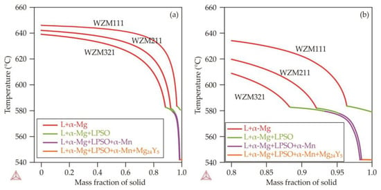
Figure 1.
(a) The nonequilibrium solidification pathway of the studied alloys according to the Sheil–Gulliver model and (b) the enlarged fragment for the mass fraction of the solid 0.8–1.
The heat-treated plates with an initial thickness of 7.1 ± 0.1 mm were subjected to rolling to a final thickness of 0.23 ± 0.2 mm through 18 passes. Rolling was carried out at two temperatures, namely 400 and 450 °C. The reduction ratio per pass was calculated by the equation where and are the plate’s thickness before and after each specific pass, respectively. The average reduction ratio per pass was 17%. The sample designations and characteristics (total reduction ratio and final thickness) selected for further research and testing are listed in Table 2.
Table 2.
Characteristics of the studied samples.
2.2. Materials
For structural studies and microhardness measurements, ND-RD longitudinal sections of size 15 × 5 mm2 were cut from rolled plates with different reductions (thickness) by the electro-spark method. The sections were embedded in epoxy resin using a SimpliMet 1000 machine (Buehler, Leinfelden-Echterdingen, Germany); after that, the sections were prepared. The sections’ surfaces were carefully ground and polished to a mirror finish. Grinding was carried out sequentially on abrasive paper with a roughness of P400, P1000, and P2500. Polishing was carried out on fabric using diamond paste. The structural studies were carried out on pre-etched sections in a solution of the following composition: 20 mL of acetic glycol, 1 mL of nitric acid, 60 mL of ethylene glycol, and 60 mL of distilled water; the microhardness was tested on unetched sections.
For tensile testing, small-sized tensile specimens with a total length of 12 mm and a length and width of the gauge part of 5 and 1.45 mm, respectively, were cut from the plates along the rolling direction by the electro-spark method. The thickness of the specimens corresponded to the thickness of the plate after rolling to a specific reduction ratio. Before the tensile test, the surfaces of the tensile specimens were not subjected to additional grinding or polishing.
2.3. Microhardness Measurement
The Vickers microhardness values were measured on samples’ longitudinal sections using a Micromet 5101 tester (load 0.5 N, load exposure time 10 s, Buehler, Leinfelden-Echterdingen, Germany). Six measurements were made randomly with the calculation of the arithmetic average and standard deviation.
2.4. Tensile Test
Tensile testing of small-sized specimens was carried out using an Instron 5966 universal testing machine (Instron, Norwood, MA, USA) with special adapters installed. The deformation rate was 0.002 s−1. During the test, the stress–strain curves were plotted using the built-in software; after that, the mechanical characteristics of the specimens were determined: the yield strength (YS), the ultimate tensile strength (UTS), and the relative elongation (RE). Three specimens per point were tested.
2.5. Structural Studies
The study of the longitudinal sections’ microstructures was carried out using an optical microscope (OM) Axio Observer D1m Carl Zeiss (Carl Zeiss, Oberkochen, Germany) with a built-in digital camera at magnifications from 50× to 1000× as well as a scanning electron microscope (SEM) Tescan Vega 3 SBH (Tescan, Brno, Czech Republic) with an Oxford energy-dispersive microanalysis attachment in the back-scattered electron mode (sensitive to the atomic mass of a chemical element) at magnifications from 200× to 5000×.
3. Results and Discussion
3.1. Microstructure Analysis
3.1.1. Microstructure of the Alloys in As-Cast and Heat Treated States
Figure 2 shows the SEM images representing the typical microstructures of the studied samples in the as-cast state and after heat treatment. As-cast alloys have a dendritic structure of a magnesium solid solution (α-Mg) and an LPSO phase with specific broken boundaries located along the boundaries of dendritic cells. According to the EDS data, almost all manganese is in α-Mg. In addition to the LPSO phase, a small amount of the Y-rich phase is observed in the structure, the composition of which is close to Mg24Y5. It corresponds to the calculations of the solidification pathway using the Sheil–Gulliver model (see Figure 1). After heat treatment, the structures of the WZM111 and WZM211 alloys are mainly homogenized, but the Mg24Y5 phase can be observed, while the open contours of the dendritic structure with fragments of the LPSO phase remain in the WZM321 alloy. These results contradict the calculated equilibrium phase composition of the WZM111 and WZM211 alloys for a temperature of 520 °C (see Table 3), according to which the WZM111 and WZM211 alloys should contain a small amount of the LPSO phase, about 3% and 8%, respectively, but are consistent with the calculation for the WZM321 alloy for the fraction of the LPSO phase which should reach 12%.
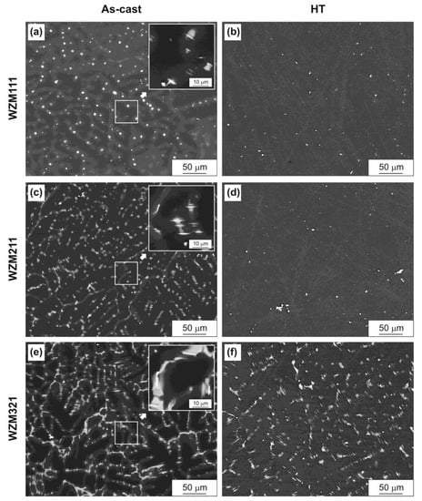
Figure 2.
Microstructure (SEM) of magnesium alloys (a,b) WZM111, (c,d) WZM211, and (e,f) WZM321: (a,c,e) as-cast state and (b,d,f) after heat treatment (HT).
Table 3.
Equilibrium phase composition (wt%) of the studied alloys at different temperatures.
3.1.2. Microstructure of the Alloys after Rolling
The plates made of the WZM211 and WZM321 alloys failed during rolling at 400 °C (the WZM211 alloy after the 6th pass, and the WZM321 alloy after the 1st pass). The rest of the plates for all rolling regimes were successfully rolled to a final thickness of 0.23 ± 0.2 mm through 18 passes.
Figure 3, Figure 4, Figure 5 and Figure 6 show the OM images representing the typical microstructures of the studied samples after rolling with different reductions. Since both variants of rolling were carried out at high homologous temperatures (0.6–0.7 Tmelt), dynamic recrystallization played the main role in the microstructure formation and grain refinement [36,37].
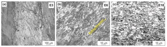
Figure 3.
Microstructure (OM) of the WZM111 alloy after rolling at 400 °C to different reductions: (a)–E3, (b)–E6, (c)–E18.
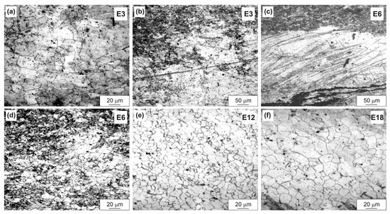
Figure 4.
Microstructure (OM) of the WZM111 alloy after rolling at 450 °C to different reductions: (a,b)–E3, (c,d)–E6, (e)–E12, (f)–E18.
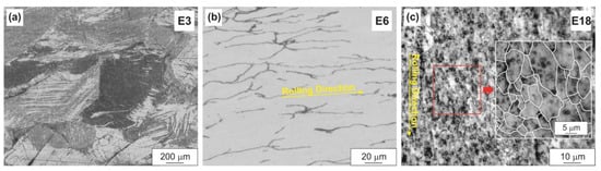
Figure 5.
Microstructure (OM) of the WZM211 alloy after rolling at 450 °C to different reductions (the grain boundaries in the insert of Figure 5c were drawn in a graphics editor): (a)–E3, (b)–E6, (c)–E18.
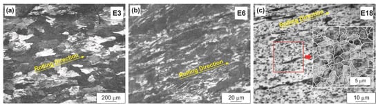
Figure 6.
Microstructure (OM) of the WZM321 alloy after rolling at 450 °C to different reductions (the grain boundaries in the insert of Figure 6c were drawn in a graphics editor): (a)–E3, (b)–E6, (c)–E18.
The evolution of the microstructure with an increase in the reduction ratio differed in the three alloys and, in addition, depended on the rolling temperature. Thus, in the WZM111 alloy, after rolling at a temperature of 400 °C to a low reduction ratio (E3), a deformed structure with numerous intersecting shear bands was observed (Figure 3a). With an increase in the reduction ratio to E6, equiaxed grains with a predominant size of 4–8 μm were formed in the alloy structure as a result of dynamic recrystallization (Figure 3b). The grains were elongated in the rolling direction. With a further increase in the reduction ratio to E18, the predominant grain size decreased to 3–5 μm, and the grain shape tended to be equiaxed (Figure 3c).
With an increase in the rolling temperature to 450 °C, the equiaxed grains in the structure of the WZM111 alloy were already formed at a reduction ratio of E3 (Figure 4a), although the deformed areas remained (Figure 4b). The predominant size of such grains was 10–20 µm. With an increase in the reduction ratio to E6–E18, an alternation of the deformed areas and the recrystallized grains was observed in the structure, and the grain size both increased and decreased with the increasing reduction ratio (Figure 4c–f). The body of many grains contained parallel slip bands. This indicates the incompleteness of the dynamic recrystallization process. In addition, the precipitating process of the α-Mn particles, which can contribute both to the recrystallized grain refinement and additional strengthening, was superimposed on the microstructure formation process. According to the calculated equilibrium phase composition of the alloys for the rolling temperatures, the fractions of the α-Mn phase in all three alloys were about 0.4% at 450 °C and about 0.6% at 400 °C (see Table 3).
In the WZM211 alloy, the dynamic recrystallization process was difficult, which is associated with the precipitation of numerous LPSO phase particles during deformation. At a low reduction ratio (E3), the structure was close to that of the WZM111 alloy after rolling at 400 °C (Figure 5a). With an increase in the reduction ratio, the deformed areas and the recrystallized grains alternated in the structure, and the developed grain structure was formed only after high reductions (E18) (Figure 5c). At the reduction value of E18, the grain size was 4–12 µm.
The dynamic recrystallization process in the WZM321 alloy was the most difficult, which is also associated with the precipitation of numerous LPSO phase particles. Thus, at a low reduction (E3), the original large grains with strongly distorted boundaries, elongated in the direction of rolling, were retained in the alloy structure (Figure 6a). The recrystallized grains began to form only at high reductions (E12). However, even after maximum reduction (E18), a slight elongation of the grains along the direction of rolling was observed (Figure 6c). At the reduction value of E18, the grain size was 3–8 µm.
Before rolling, as noted above, the LPSO phase particles were present only in the WZM321 alloy. During rolling, the LPSO phase particles precipitated in the WZM211 and WZM321 alloys, which hinders dynamic recrystallization. As an example, Figure 7 shows SEM images of the WZM321 alloy structure after rolling with different reductions. At low reductions (E3-E6), the structure contains large particles of the LPSO phase, up to 50 µm in length (particles of Type 1 in Figure 7). These particles were present in the structure of the alloy before rolling. With an increase in the reductions (E12–E18), large particles of the LPSO phase were elongated in the direction of rolling, and fine particles of the LPSO phase, 0.5–2 µm in size, precipitated in the structure (particles of Type 2 in Figure 7).
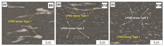
Figure 7.
SEM images of the microstructure of the WZM321 alloy after rolling at 450 °C to different reductions: (a)–E6, (b)–E12, (c)–E18.
3.2. Mechanical Properties
3.2.1. Microhardness Measurement
Table 4 shows the average microhardness values of the studied alloys depending on the rolling temperature and the reduction ratio. It can be seen that an increase in the rolling temperature does not have a strong effect on the change in microhardness. At the same rolling temperature (450 °C), the average (for all reductions) microhardness increases in the following order: the WZM111 alloy, the WZM211 alloy, and the WZM321 alloy, 75, 85, and 91 HV, respectively.
Table 4.
Microhardness (HV) of the studied alloys after rolling.
Changes in the microhardness values ambiguously correlate with changes in the microstructure. Thus, only for the WZM211 alloy, a noticeable decrease in the microhardness was observed with an increase in the reduction ratio from E3 to E6–E18, which can be associated with the development of the dynamic recrystallization process [38]. For other alloys, with an increase in the reduction ratio from E3 to E18, the microhardness either did not change or fluctuated slightly, which can be associated with the competition of the hardening process caused by the accumulation of dislocations and the precipitation of the α-Mn/LPSO-phase particles and the softening process caused by a decrease in the dislocation density due to dynamic recrystallization. At the same time, it is difficult to estimate the contribution of the dynamically recrystallized grain size to the hardening of the alloy through the Hall–Petch relation due to the highly inhomogeneous microstructure and dislocation structure: the presence of the second phase particles, the presence of deformed regions with a high dislocation density, and the presence of a dynamically recrystallized structure with a reduced dislocation density.
The weak sensitivity of the microhardness of different alloys to the reduction ratio in the E6–E12 range can be associated either with the rapid activation of the dynamic recrystallization process already at low reductions (for the WZM111 alloy) or vice versa with the difficulty of the dynamic recrystallization process (for the WZM211 and WZM321 alloys).
3.2.2. Tensile Tests
Table 5, Table 6, Table 7 and Table 8 present the averaged (over three specimens) values of the mechanical properties of the studied alloys obtained in tensile testing, depending on the rolling temperature and the reduction ratio. The typical stress–strain curves for the samples are shown in Figure 8, Figure 9, Figure 10 and Figure 11. For clarity, the histograms of the distribution of mechanical properties for each alloy were plotted depending on the rolling temperature and the reduction ratio (Figure 12, Figure 13, Figure 14 and Figure 15).
Table 5.
Mechanical properties of the WZM111 alloy after rolling at a temperature of 400 °C.
Table 6.
Mechanical properties of the WZM111 alloy after rolling at a temperature of 450 °C.
Table 7.
Mechanical properties of the WZM211 alloy after rolling at a temperature of 450 °C.
Table 8.
Mechanical properties of the WZM321 alloy after rolling at a temperature of 450 °C.
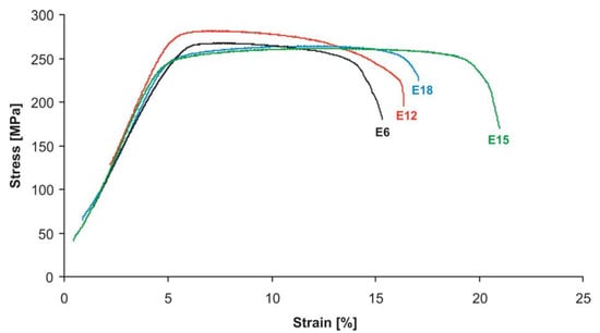
Figure 8.
Typical stress–strain curves of the WZM111 alloy samples after rolling at 400 °C.
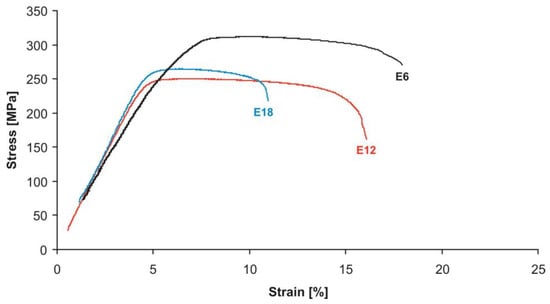
Figure 9.
Typical stress–strain curves of the WZM111 alloy samples after rolling at 450 °C.
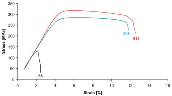
Figure 10.
Typical stress–strain curves of the WZM211 alloy samples after rolling at 450 °C.
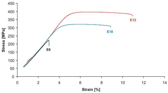
Figure 11.
Typical stress–strain curves of the WZM321 alloy samples after rolling at 450 °C.
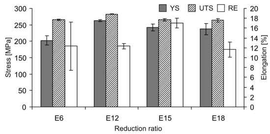
Figure 12.
Dependence of the YS, UTS, and RE of the WZM111 alloy on the reduction ratio after rolling at a temperature of 400 °C.
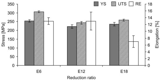
Figure 13.
Dependence of the YS, UTS, and RE of the WZM111 alloy on the reduction ratio after rolling at a temperature of 450 °C.
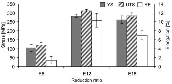
Figure 14.
Dependence of the YS, UTS, and RE of the WZM211 alloy on the reduction ratio after rolling at a temperature of 450 °C.
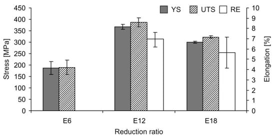
Figure 15.
Dependence of the YS, UTS, and RE of the WZM321 alloy on the reduction ratio after rolling at a temperature of 450 °C.
The change in the mechanical properties correlates well with the change in the microstructure. Thus, for the WZM111 alloy, after rolling at 400 °C with an increase in the reduction ratio from E6 to E12, an increase in strength was observed (especially in the yield strength, by 30%), and with a further increase in the reduction ratio to E15–E18, the strength decreased monotonically (by 7–10%), which is associated with more complete dynamic recrystallization. For the WZM111 alloy, after rolling at 450 °C with an increase in the reduction ratio from E6 to E12, the strength, on the contrary, first decreased (by 12–21%) and then increased (by 6%) with a further increase in the reduction ratio to E18. At the same time, an increase in the rolling temperature from 400 to 450 °C at low reductions caused an increase in strength, and at high reductions, this caused a decrease in ductility.
During the tensile test of the WZM211 and WZM321 alloy specimens after rolling to a low reduction ratio, their failure could occur even in the elastic region at low stresses due to surface cracks formed during rolling. However, with an increase in the reduction ratio, such cracks heal, which leads to an increase in strength, and the specimens deformed with the development of the neck, which indicates a high ductility of the material. With an increase in the reduction ratio from E12 to E18, the strength of the WZM211 and WZM321 alloys decreased (by 7–9% and 17–18%, respectively). In addition, at the same rolling temperature (450 °C), the transition from the E12 to E18 reduction for all three alloys caused a decrease in the relative elongation, i.e., ductility. A decrease in strength can be explained by a decrease in the dislocation density as a result of a more complete dynamic recrystallization process. The decrease in ductility can be explained by the presence of a surface defective layer, the negative effect of which will be stronger with a decrease in the sample’s thickness (or with an increase in the reduction ratio).
The most attractive balance of strength and ductility for all three alloys was achieved after rolling with the E12–E18 reductions.
At the same rolling temperature (450 °C) and high reductions (E12–E18), the strength increased in the following order: the WZM111 alloy, the WZM211 alloy, and the WZM321 alloy, which correlates with their microhardness as well as with the amount of the LPSO phase that precipitated in their structure after rolling. In this case, the change in their relative elongation had an inverse relationship.
It is of interest to compare the achieved mechanical properties with those of other Mg–Zn–Y alloys. For example, for a comparable reduction ratio (~90%) of hot rolling, the yield strength of the WZM111 alloy significantly (by a factor of 1.3–2) exceeds that of Mg–(3–9)Zn–(0.6–2)Y alloys, but it is inferior to them in ductility [21]. Accordingly, for the WZM211 and WZM321 alloys, the strength advantage is even greater. Thus, the achieved strength of the studied alloys exceeds the strength of other hot-rolled alloys of the Mg–Zn–Y system. The mechanical properties of the hot-rolled WZM321 alloy with the greatest strength can be compared with the properties of Mg–Zn–Y alloys after hot extrusion [22,39].
The requirements for biomaterials purposed for bone fixtures are a strength higher than 200 MPa and a relative elongation greater than 10% [3,11]. Through this study, we were able to ascertain that the WZM111 and WZM211 alloys processed by hot rolling at 450 °C possess the provided requirements, which make them suitable for applications in bone implants. The WZM321 alloy has a great strength performance but a low relative elongation. Possibly annealing applied to the alloy can increase its relative elongation, and this should be established in future research.
The thickness of the samples achieved after rolling with the E12–E18 reductions was 0.8–0.2 mm. In accordance with the literature, the lower value is close to the thickness of barrier membranes in dental surgery [40], and the higher value is close to the thickness of biodegradable plates [19,20]. Further research will be focused on corrosion properties and biocompatibility investigation of Mg–Y–Zn–Mn alloys in order to choose the best alloy composition with a low corrosion rate (<0.5 mm/year) [3,11]. In addition, it is important to study the texture, whose contribution has a strong influence on the formation of the mechanical properties of magnesium alloys [13,15,38].
4. Conclusions
Based on the results of this study on the effects of the rolling temperature and the reduction ratio on the structure and mechanical properties of the WZM111, WZM211, and WZM321 alloys, it was established that:
(1) All alloys were successfully rolled at 450 °C to reductions up to 97%, while only the WZM111 alloy was successfully rolled at 400 °C;
(2) During hot rolling, the dynamic recrystallization process occurs, and this process proceeds most easily and with most difficulty in the WZM111 and WZM321 alloys, respectively;
(3) During hot rolling, the LPSO phase particles precipitate in the structure of the WZM211 and WZM321 alloys;
(4) At high reductions (96–97%), an increase in the rolling temperature from 400 to 450 °C has little effect on the strength of the WZM111 alloy but reduces its ductility. At the same rolling temperature (450 °C) and at high reductions, the strength increases in the following order: the WZM111 alloy, the WZM211 alloy, and the WZM321 alloy, while ductility has an inverse relationship;
(5) The most attractive balance of strength and ductility for all three alloys is achieved after rolling to total reduction ratios of 88–97%. The achieved strength of all three alloys exceeds the strength of other hot-rolled alloys of the Mg–Zn–Y system, but they are inferior to them in ductility, while the mechanical properties of the hot-rolled WZM321 alloy with the greatest strength can be compared with the properties of Mg–Zn–Y alloys after hot extrusion.
Author Contributions
Conceptualization, V.E.B., A.A.K. and A.Y.D.; methodology, V.E.B. and S.O.R.; investigation, S.O.R., A.V.L., D.V.T. and V.V.Y.; writing—original draft preparation, S.O.R.; writing—review and editing, V.E.B.; visualization, S.O.R.; funding acquisition, K.S.S. All authors have read and agreed to the published version of the manuscript.
Funding
The authors are grateful to the Ministry of Science and Higher Education of the Russian Federation for financial support under the Megagrant (No. 075-15-2022-1133).
Institutional Review Board Statement
Not applicable.
Informed Consent Statement
Not applicable.
Data Availability Statement
The raw/processed data required to reproduce these findings cannot be shared at this time as the data also forms part of an ongoing study.
Acknowledgments
We thank N. Munzaferova for help with research.
Conflicts of Interest
The authors declare no conflict of interest.
References
- Gareb, B.; Van Bakelen, N.B.; Vissink, A.; Bos, R.R.M.; Van Minnen, B. Titanium or Biodegradable Osteosynthesis in Maxillofacial Surgery? In Vitro and In Vivo Performances. Polymers 2022, 14, 2782. [Google Scholar] [CrossRef] [PubMed]
- Vujović, S.; Desnica, J.; Stanišić, D.; Ognjanović, I.; Stevanovic, M.; Rosic, G. Applications of Biodegradable Magnesium-Based Materials in Reconstructive Oral and Maxillofacial Surgery: A Review. Molecules 2022, 27, 5529. [Google Scholar] [CrossRef] [PubMed]
- Kraus, T.; Fischerauer, S.F.; Hänzi, A.C.; Uggowitzer, P.J.; Löffler, J.F.; Weinberg, A.M. Magnesium alloys for temporary implants in osteosynthesis: In vivo studies of their degradation and interaction with bone. Acta Biomater. 2012, 8, 1230–1238. [Google Scholar] [CrossRef] [PubMed]
- Staiger, M.P.; Pietak, A.M.; Huadmai, J.; Dias, G. Magnesium and its alloys as orthopedic biomaterials: A review. Biomaterials 2006, 27, 1728–1734. [Google Scholar] [CrossRef]
- Gu, X.-N.; Li, S.-S.; Li, X.-M.; Fan, Y.-B. Magnesium based degradable biomaterials: A review. Front. Mater. Sci. 2014, 8, 200–218. [Google Scholar] [CrossRef]
- Tran, N.T.; Kim, Y.-K.; Kim, S.-Y.; Lee, M.-H.; Lee, K.-B. Comparative Osteogenesis and Degradation Behavior of Magnesium Implant in Epiphysis and Diaphysis of the Long Bone in the Rat Model. Materials 2022, 15, 5630. [Google Scholar] [CrossRef]
- Gu, X.-N.; Zheng, Y.-F. A review on magnesium alloys as biodegradable materials. Front. Mater. Sci. China 2010, 4, 111–115. [Google Scholar] [CrossRef]
- Nguyen, A.; Kunert, M.; Hort, N.; Schrader, C.; Weisser, J.; Schmidt, J. Cytotoxicity of the Ga-containing coatings on biodegradable magnesium alloys. Surf. Innov. 2015, 3, 10–19. [Google Scholar] [CrossRef]
- Rider, P.; Kačarević, Ž.P.; Elad, A.; Rothamel, D.; Sauer, G.; Bornert, F.; Windisch, P.; Hangyási, D.; Molnar, B.; Hesse, B.; et al. Biodegradation of a Magnesium Alloy Fixation Screw Used in a Guided Bone Regeneration Model in Beagle Dogs. Materials 2022, 15, 4111. [Google Scholar] [CrossRef]
- Delsmann, M.M.; Stürznickel, J.; Kertai, M.; Stücker, R.; Rolvien, T.; Rupprecht, M. Radiolucent zones of biodegradable magnesium-based screws in children and adolescents—A radiographic analysis. Arch. Orthop. Trauma Surg. 2022. [Google Scholar] [CrossRef]
- Chen, Y.; Xu, Z.; Smith, C.; Sankar, J. Recent advances on the development of magnesium alloys for biodegradable implants. Acta Biomater. 2014, 10, 4561–4573. [Google Scholar] [CrossRef] [PubMed]
- Sun, Y.; Zhang, B.; Wang, Y.; Geng, L.; Jiao, X. Preparation and characterization of a new biomedical Mg–Zn–Ca alloy. Mater. Des. 2012, 34, 58–64. [Google Scholar] [CrossRef]
- Zhang, B.; Wang, Y.; Geng, L.; Lu, C. Effects of calcium on texture and mechanical properties of hot-extruded Mg–Zn–Ca alloys. Mater. Sci. Eng. A 2012, 539, 56–60. [Google Scholar] [CrossRef]
- Tong, L.B.; Zheng, M.Y.; Hu, X.S.; Wu, K.; Xu, S.W.; Kamado, S.; Kojima, Y. Influence of ECAP routes on microstructure and mechanical properties of Mg–Zn–Ca alloy. Mater. Sci. Eng. A 2010, 527, 4250–4256. [Google Scholar] [CrossRef]
- Tong, L.B.; Zheng, M.Y.; Xu, S.W.; Kamado, S.; Du, Y.Z.; Hu, X.S.; Wu, K.; Gan, W.M.; Brokmeier, H.G.; Wang, G.J.; et al. Effect of Mn addition on microstructure, texture and mechanical properties of Mg–Zn–Ca alloy. Mater. Sci. Eng. A 2011, 528, 3741–3747. [Google Scholar] [CrossRef]
- Geng, L.; Zhang, B.P.; Li, A.B.; Dong, C.C. Microstructure and mechanical properties of Mg–4.0Zn–0.5Ca alloy. Mater. Lett. 2009, 63, 557–559. [Google Scholar] [CrossRef]
- Bian, D.; Zhou, W.; Deng, J.; Liu, Y.; Li, W.; Chu, X.; Xiu, P.; Cai, H.; Kou, Y.; Jiang, B.; et al. Development of magnesium-based biodegradable metals with dietary trace element germanium as orthopaedic implant applications. Acta Biomater. 2017, 64, 421–436. [Google Scholar] [CrossRef]
- Niu, J.; Yuan, G.; Liao, Y.; Mao, L.; Zhang, J.; Wang, Y.; Huang, F.; Jiang, Y.; He, Y.; Ding, W. Enhanced biocorrosion resistance and biocompatibility of degradable Mg–Nd–Zn–Zr alloy by brushite coating. Mater. Sci. Eng. C 2013, 33, 4833–4841. [Google Scholar] [CrossRef]
- Naujokat, H.; Seitz, J.-M.; Açil, Y.; Damm, T.; Möller, I.; Gülses, A.; Wiltfang, J. Osteosynthesis of a cranio-osteoplasty with a biodegradable magnesium plate system in miniature pigs. Acta Biomater. 2017, 62, 434–445. [Google Scholar] [CrossRef]
- Byun, S.-H.; Lim, H.-K.; Cheon, K.-H.; Lee, S.-M.; Kim, H.-E.; Lee, J.-H. Biodegradable magnesium alloy (WE43) in bone-fixation plate and screw. J. Biomed. Mater. Res. Part B Appl. Biomater. 2020, 108, 2505–2512. [Google Scholar] [CrossRef]
- Lee, J.Y.; Kim, D.H.; Lim, H. Effects of Zn/Y ratio on microstructure and mechanical properties of Mg-Zn-Y alloys. Mater. Lett. 2005, 59, 3801–3805. [Google Scholar] [CrossRef]
- Okayasu, M.; Takeuchi, S.; Matsushita, M.; Tada, N.; Yamasaki, M.; Kawamura, Y. Mechanical properties and failure characteristics of cast and extruded Mg97Y2Zn1 alloys with LPSO phase. Mater. Sci. Eng. A 2016, 652, 14–29. [Google Scholar] [CrossRef]
- Singh, A.; Osawa, Y.; Somekawa, H.; Mukai, T. Ultra-fine grain size and isotropic very high strength by direct extrusion of chill-cast Mg–Zn–Y alloys containing quasicrystal phase. Scr. Mater. 2011, 64, 661–664. [Google Scholar] [CrossRef]
- Tahreen, N.; Chen, D.L. A Critical Review of Mg-Zn-Y Series Alloys Containing I, W, and LPSO Phases. Adv. Eng. Mater. 2016, 18, 1983–2002. [Google Scholar] [CrossRef]
- Xu, D.K.; Tang, W.N.; Liu, L.; Xu, Y.B.; Han, E.H. Effect of W-phase on the mechanical properties of as-cast Mg–Zn–Y–Zr alloys. J. Alloys Compd. 2008, 461, 248–252. [Google Scholar] [CrossRef]
- Luo, Z.P.; Zhang, S.Q. High-resolution electron microscopy on the X-Mg12ZnY phase in a high strength Mg-Zn-Zr-Y magnesium alloy. J. Mater. Sci. Lett. 2000, 19, 813–815. [Google Scholar] [CrossRef]
- Bazhenov, V.E.; Saidov, S.S.; Tselovalnik, Y.V.; Voropaeva, O.O.; Plisetskaya, I.V.; Tokar, A.A.; Bazlov, A.I.; Bautin, V.A.; Komissarov, A.A.; Koltygin, A.V.; et al. Comparison of castability, mechanical, and corrosion properties of Mg-Zn-Y-Zr alloys containing LPSO and W phases. Trans. Nonferrous Met. Soc. China 2021, 31, 1276–1290. [Google Scholar] [CrossRef]
- Bakhsheshi-Rad, H.R.; Idris, M.H.; Abdul-Kadir, M.R.; Ourdjini, A.; Medraj, M.; Daroonparvar, M.; Hamzah, E. Mechanical and bio-corrosion properties of quaternary Mg–Ca–Mn–Zn alloys compared with binary Mg–Ca alloys. Mater. Des. 2014, 53, 283–292. [Google Scholar] [CrossRef]
- Ibrahim, H.; Moghaddam, N.; Elahinia, M. Mechanical and In Vitro Corrosion Properties of a Heat-Treated Mg-Zn-Ca-Mn Alloy as a Potential Bioresorbable Material. Adv. Metall. Mater. Eng. 2017, 1, 1–7. [Google Scholar] [CrossRef]
- Yandong, Y.; Shuzhen, K.; Teng, P.; Jie, L.; Caixia, L. Effects of Mn Addition on the Microstructure and Mechanical Properties of As-cast and Heat-Treated Mg-Zn-Ca Bio-magnesium Alloy. Metallogr. Microstruct. Anal. 2015, 4, 381–391. [Google Scholar] [CrossRef]
- She, J.; Pan, F.S.; Guo, W.; Tang, A.T.; Gao, Z.Y.; Luo, S.Q.; Song, K.; Yu, Z.W.; Rashad, M. Effect of high Mn content on development of ultra-fine grain extruded magnesium alloy. Mater. Des. 2016, 90, 7–12. [Google Scholar] [CrossRef]
- Cho, D.H.; Lee, B.W.; Park, J.Y.; Cho, K.M.; Park, I.M. Effect of Mn addition on corrosion properties of biodegradable Mg-4Zn-0.5Ca-xMn alloys. J. Alloys Compd. 2017, 695, 1166–1174. [Google Scholar] [CrossRef]
- Lu, R.; Jiao, K.; Zhao, Y.; Li, K.; Yao, K.; Hou, H. Influence of Long-Period-Stacking Ordered Structure on the Damping Capacities and Mechanical Properties of Mg-Zn-Y-Mn As-Cast Alloys. Materials 2020, 13, 4654. [Google Scholar] [CrossRef] [PubMed]
- Li, D.; Zhang, J.; Que, Z.; Xu, C.; Niu, X. Effects of Mn on the microstructure and mechanical properties of long period stacking ordered Mg95Zn2.5Y2.5 alloy. Mater. Lett. 2013, 109, 46–50. [Google Scholar] [CrossRef]
- Qi, F.; Zhang, D.; Zhang, X.; Xu, X. Effects of Mn addition and X-phase on the microstructure and mechanical properties of high-strength Mg–Zn–Y–Mn alloys. Mater. Sci. Eng. A 2014, 593, 70–78. [Google Scholar] [CrossRef]
- Doherty, R.D.; Hughes, D.A.; Humphreys, F.J.; Jonas, J.J.; Juul Jensen, D.; Kassner, M.E.; King, W.E.; McNelley, T.R.; McQueen, H.J.; Rollett, A.D. Current issues in recrystallization: A review. Mater. Sci. Eng. A 1997, 238, 219–274. [Google Scholar] [CrossRef]
- Sakai, T.; Belyakov, A.; Kaibyshev, R.; Miura, H.; Jonas, J.J. Dynamic and post-dynamic recrystallization under hot, cold and severe plastic deformation conditions. Prog. Mater. Sci. 2014, 60, 130–207. [Google Scholar] [CrossRef]
- He, Y.-B.; Pan, Q.-L.; Chen, Q.; Zhang, Z.-Y.; Liu, X.-Y.; Li, W.-B. Modeling of strain hardening and dynamic recrystallization of ZK60 magnesium alloy during hot deformation. Trans. Nonferrous Met. Soc. China 2012, 22, 246–254. [Google Scholar] [CrossRef]
- Tong, L.B.; Li, X.H.; Zhang, H.J. Effect of long period stacking ordered phase on the microstructure, texture and mechanical properties of extruded Mg–Y–Zn alloy. Mater. Sci. Eng. A 2013, 563, 177–183. [Google Scholar] [CrossRef]
- Rider, P.; Kačarević, Ž.P.; Elad, A.; Tadic, D.; Rothamel, D.; Sauer, G.; Bornert, F.; Windisch, P.; Hangyási, D.B.; Molnar, B.; et al. Biodegradable magnesium barrier membrane used for guided bone regeneration in dental surgery. Bioact. Mater. 2022, 14, 152–168. [Google Scholar] [CrossRef]


Disclaimer/Publisher’s Note: The statements, opinions and data contained in all publications are solely those of the individual author(s) and contributor(s) and not of MDPI and/or the editor(s). MDPI and/or the editor(s) disclaim responsibility for any injury to people or property resulting from any ideas, methods, instructions or products referred to in the content. |
© 2023 by the authors. Licensee MDPI, Basel, Switzerland. This article is an open access article distributed under the terms and conditions of the Creative Commons Attribution (CC BY) license (https://creativecommons.org/licenses/by/4.0/).