Article

Enhanced Productivity of Bottom-Blowing Copper-Smelting Process Using Plume Eye

1
Faculty of Materials Metallurgy and Chemistry, Jiangxi University of Science and Technology, Ganzhou 341000, China
2
Dongying Fangyuan Nonferrous Metals, Dongying 257000, China
3
Sustainable Minerals Institute, University of Queensland, Brisbane 4072, Australia
*
Author to whom correspondence should be addressed.
Metals 2023, 13(2), 217; https://doi.org/10.3390/met13020217
Submission received: 20 December 2022 / Revised: 13 January 2023 / Accepted: 19 January 2023 / Published: 23 January 2023
(This article belongs to the Special Issue Fundamentals of Advanced Pyrometallurgy)

Abstract

:
Bottom-blowing copper smelting is a bath smelting technology recently developed in China. It has the advantages of good adaptability of raw materials, high oxygen utilization and thermal efficiency, and flexible production capacity. Plume eye is a unique phenomenon observed in the bottom-blowing copper-smelting furnace where the slag on the surface of the bath is pushed away by the high-pressure gas injected from the bottom. The existence of plume eye was first confirmed by analyzing the quenched industrial samples collected above the gas injection area and then investigated by laboratory water model experiments. Combining the plant operating data and the smelting mechanism of the copper concentrate, the role of the plume eye in bottom-blowing-enhanced smelting is analyzed. It reveals that the direct dissolution of copper concentrate as a low-grade matte into the molten matte can significantly accelerate the reactions between the concentrate and oxygen. The productivity of the bottom-blowing furnace is therefore increased as a result. The effects of the gas flow rate and thickness of the matte and of the slag layer on the diameter of the plume eye were studied using water-model experiments. It was found that increasing the gas flow and the thickness of the matte and reducing the thickness of the slag can increase the diameter of the plume eye. This work is of great significance for further understanding the copper bottom-blowing smelting technology and optimizing industrial operations.

1. Introduction

The concept of the plume eye was first proposed in steelmaking [1,2,3,4,5,6,7,8,9]. Plume eye was a description of the exposure of lower-layer liquid due to upper-layer liquid being pushed away because of high-pressure gas injection [2]. In a steel ladle, a large plume eye is not desirable because it can result in oxygen and nitrogen pick up by the steel, which can affect the steel quality [3]. Similarly, a large plume eye in steel tundish can lead to the formation of inclusion and slag entrainment because of the metal-liquid re-oxidation reactions [4]. To investigate the nature of the plume eye in steel ladle, the researchers used water to simulate the metal and oil to simulate slag [2,4,5,6,7]. The control of the plume eye size was the primary interest in the steel ladle [3,4,8,9].
Bottom blowing is a copper-smelting technology that was proposed in China in the 1990s [10]. Its unique technical characteristics, including good raw material adaptability, high oxygen utilization rate and thermal efficiency, and flexible production capacity [11,12,13,14,15], have attracted strong interest in the copper industry [16,17,18,19,20,21,22,23,24]. From November 1991 to June 1992, a plant trial was conducted at Shuikoushan (SKS) Smelter for 217 days to smelt copper concentrate in a bottom-blowing furnace [16,17]. In 2005, the first industrial scope BBF (Bottom-blowing furnace ) was built in the Sin Quyen smelter in Vietnam. The size of the furnace was Ø3.8 m × 11.5 m and the capacity was designed to be 10,000 t Cu per year [18]. However, the BBF in the Sin Quyen smelter seemed to be operating incorrectly, as no operating details were reported. In 2008, the first real commercialized BBF started in Dongying Fangyuan Nonferrous Metals (Fangyuan, Shangdong) [19,20]. The oxygen-enriched bottom-blown matte smelting of Shandong Humon Smelting Co., Ltd. (Yantai, China) was successfully put into production in April 2010. After nearly five months of trial production, the unique advantages of this process in energy conservation, environmental protection, safety, and other aspects have been fully demonstrated [21]. In 2011, the bottom-blown furnace (Ø3.8 m × 13.5 m) of Baotou Huading Copper Industry Development Co., Ltd. (Baotou, China) was officially put into operation, with an average feeding capacity of 28 t/h and a matte grade of about 50% [22,23]. Thirteen BBS furnaces were constructed or were under construction with the capacity of 1600 kt/a copper production until 2016. The furnace size ranged from Ø3.8 m × 11.5 m to Ø5.8 m × 30 m [24]. During the operation of oxygen bottom-blowing bath smelting, high-pressure oxygen-enriched air is injected into liquid matte from the bottom to provide oxygen for copper-concentrate smelting reactions and to strongly stir the bath. It has been observed by the authors directly from the feeding mouth that the plume eye exists in the oxygen bottom-blowing furnace (BBF). The high-pressure oxygen-enriched air pushes away the slag layer on the surface of the bath above the oxygen lance area, exposing the matte to the feeding mouth. The copper-smelting furnace is a horizontal cylindrical vessel, which is geometrically different from a steelmaking ladle or tundish. In addition, the upper layer in the steel ladle or tundish is skinny in comparison to the lower-layer thickness, but the upper slag layer is considerably thick in copper-smelting furnaces. Therefore, the behavior of the plume eye in a copper-smelting furnace is different from that in a steelmaking ladle or tundish. The fundamental studies, including the thermodynamics of the slag and fluid dynamic of the molten bath, have been extensively conducted in recent years to understand and support the new technology [10,25,26]. However, few studies were reported on the plume eye in the bottom-blowing copper-smelting process. Jiang et al. [27] studied the influencing factors of plume eye using the laboratory water model.
This study aims to confirm the existence of plume eye and investigate the reaction mechanisms in a copper bottom-blowing smelting furnace by analyzing the industrial samples collected above the reaction region. The parameters to control the size of the plume eye will be studied using laboratory water-model experiments to provide information for industry operation.

2. Research Methods

2.1. Sampling and Analysis of Industrial Samples

Figure 1 shows a schematic diagram of an oxygen bottom-blowing smelting furnace. The industrial samples were collected from a bottom-blowing copper-smelting furnace (φ3.3 m × 15 m) in Dongying Fangyuan Nonferrous Metals Co., Ltd., Dongying City, China. [10]. A long cold iron rod is stretched into the furnace from the feeding mouth and the sample sprayed above the oxygen lance area stuck on the iron rod and cooled rapidly. The slag sample was collected from the tapping hole using a long cold iron rod dipped into the slag flow. All the quenched samples, including the splash sample and slag sample, were mounted in epoxy resin, polished, and carbon coated for electron probe microanalysis (EPMA). A JXA 8200 Electron Probe Microanalyser (Japan Electron Optics Ltd., Tokyo, Japan) with Wavelength Dispersive Spectroscopy (WDS, Japan Electron Optics Ltd., Tokyo, Japan) was used for the microstructural and compositional analyses. The EPMA was operated on at an accelerating voltage of 15 kV and a probe current of 15 nA. The beam size was set to “0 μm” to accurately measure the composition of an area larger than 1 μm. The ZAF (Z is atomic number correction factor, A is absorption correction factor, and F is fluorescence correction factor) correction procedure was applied for the data analysis. “The standards used for the analysis were from Charles M. Taylor Co. (Stanford, CA, USA): Al2O3 for Al, MgO for MgO, Fe2O3 for Fe, Cu2O for Cu, KAlSi3O8 for K, PbS for Pb, GaAs for As, CaMoO4 for Mo, CaSiO3 for Si and Ca and CuFeS2 for Cu Fe and S, and Micro-Analysis Consultant Ltd. (Cambridge, UK): ZnO for Zn”. The average accuracy of the composition measured using EPMA is within 1 wt%.

2.2. Water Model Experiment

A horizontal cylindrical reactor was designed according to the ratio of 1:10 of the size of the industrial bottom-blowing copper-smelting furnace. The front view and side view of the reactor are shown in Figure 2a and b, respectively. In this study, high-pressure air was injected into the furnace through the bottom lance. Water and silicone oil at 25 °C have similar kinematic viscosities to matte (8 × 10⁻⁷ m2/s) and slag (6 × 10⁻⁶ m2/s) at 1200 °C [28]. The ratio of water density to silicon oil density is close to that of the matte density to slag density. Water and silicone oil were used to simulate matte and slag, respectively. Low density silicone oil located on the upper part of the molten pool can be a good observation of “plume eye”.
At the beginning of each experiment, the liquid bath was flashed with high-pressure air for 20 min to stabilize the flow field of the bath in the furnace. The schematic diagram of the plume eye generated in the model furnace is shown in Figure 3. Since the upper liquid is yellow silicone oil, it is easy to distinguish the shape and size of the plume eye. The plume eye was pictured with a high-speed camera and then the diameter Di of the “plume eye” was measured compared to the width of the upper liquid (D5) from the pictures. By measuring the ratio of the real width of the slag to D5, the diameter of the actual plume eye in the water model can be obtained. The diameter D of the plume eye was determined by calculating the average of ten measures in different directions.

3. Results

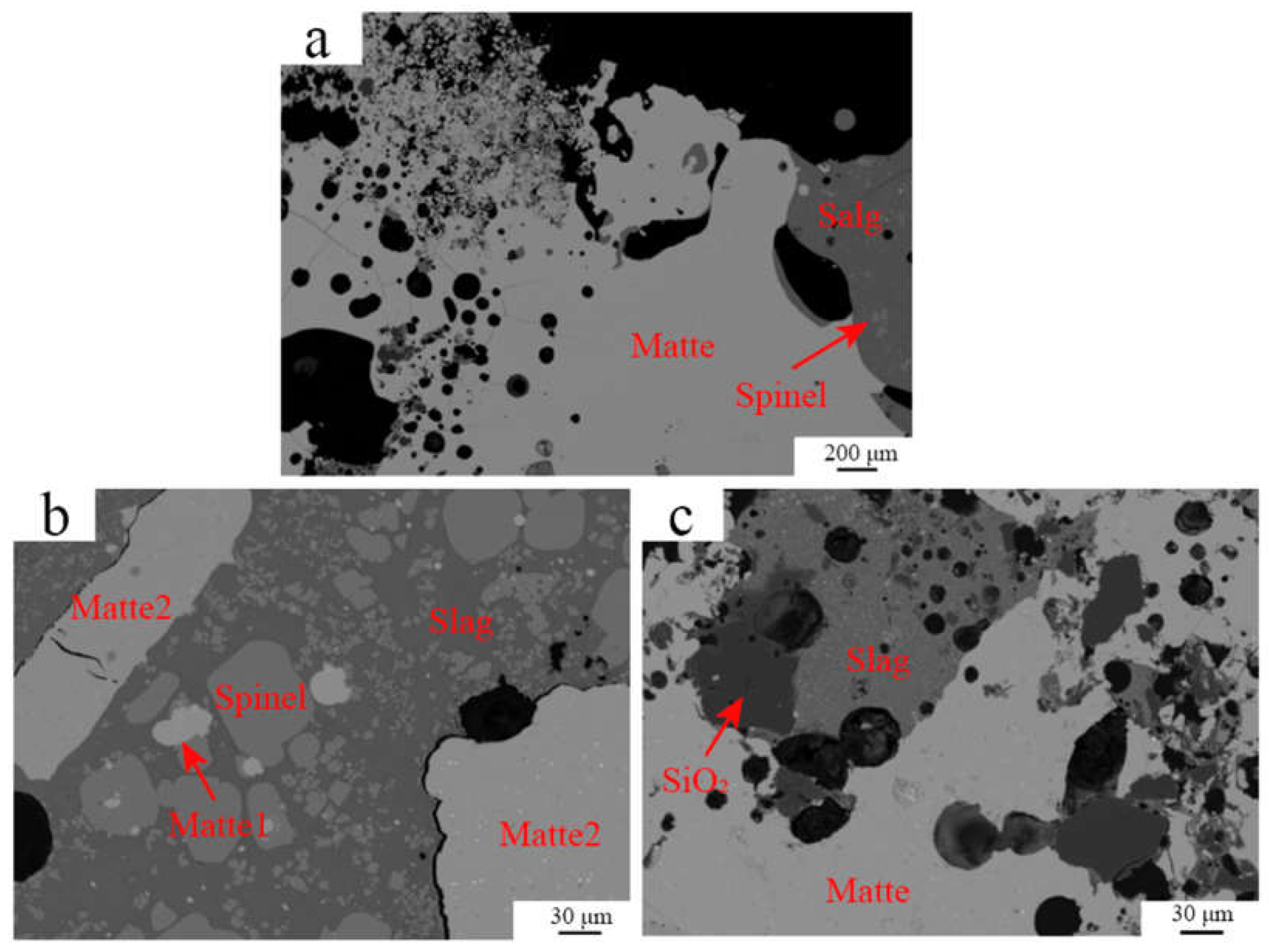
3.1. Analysis of Industrial Samples

Figure 4 shows a typical microstructure of the quenched slag extracted from the tapping hole. The temperature of the tapping slag was approximately 1180 °C. It can be seen from the figure that liquid, spinel, and matte existed in the quenched slag. Spinel is a primary phase that retained its shapes and compositions on quenching. The presence of the spinel phase indicates that the operating temperature of the furnace (1180 °C) was lower than the liquidus temperature (1350 °C) of the slag, which is the feature of the BBF [29].
Table 1 provides the compositions of the liquid, spinel, and matte phases measured using EPMA. It can be seen that the spinel mainly contains “FeO” (FeOx) causing the Fe/SiO2 ratio in the liquid phase to be lower than that of the bulk slag. In addition to “FeO” and SiO2, ZnO, Al2O3, CaO, MgO, and K2O also exist in the liquid. It is noted that the dissolved Cu2O in the liquid phase is only 0.2 wt%. The matte grade entrained in the slag is consistent with the matte grade collected at the matte tapping hole, both of which are 70% Cu.
Figure 5 shows the typical microstructures of the splashed samples extracted simultaneously above the lance area. The compositions of all the phases present in the splashed samples are presented in Table 2 and Table 3. It can be seen from Figure 5a–c that the matte phase dominates the splashed samples confirming the existence of the plume eye in the BBF.
Figure 5a shows a larger matte together with slag is present. It is seen from Table 2 and Table 3 that the Fe/SiO2 ratio in the liquid slag is 1.42 and the matte grade is 70.4% in the splashed sample 1#. These values are close to those in the final slag shown in Table 1, indicating that the splashed sample 1# is approaching the equilibrium. Figure 5b shows the existence of large and small pieces of matte together with the slag. A large proportion of solid spinel is present in the slag. The Fe/SiO2 of the liquid slag in the splash sample 2# is 0.99, which is much lower than that in the final slag. In addition, the large matte phase contains 64.2% Cu, which is lower than that in the final matte. Therefore, the splash sample 2# is still in the matte-forming reaction stage. Further oxidation of the low-grade matte will increase the Fe/SiO2 ratio in the slag and the Cu concentration in the matte. In sample 3#, the undissolved SiO2 is together with the large matte as shown in Figure 5c. The Fe/SiO2 in the splash sample 3# is 0.92 and the matte grade is 66.2. It seems that the local SiO2 concentration in the slag is too high and SiO2 is the primary phase. Further oxidation of the low-grade matte will increase the “FeO” concentration in the slag and dissolve the SiO2 phase.
The analyses of the splash samples collected above the lance area indicate that the equilibrated and unequilibrated matte were brought to the surface of the bath by the high-pressure gas. A plume eye exits in this area without slag coverage above the matte. The low-grade matte and low Fe/SiO2 slag in the splash samples indicate that the smelting reactions are mainly inside the matte layer since the oxygen is injected from the bottom of the bath and is almost completely consumed in the matte.

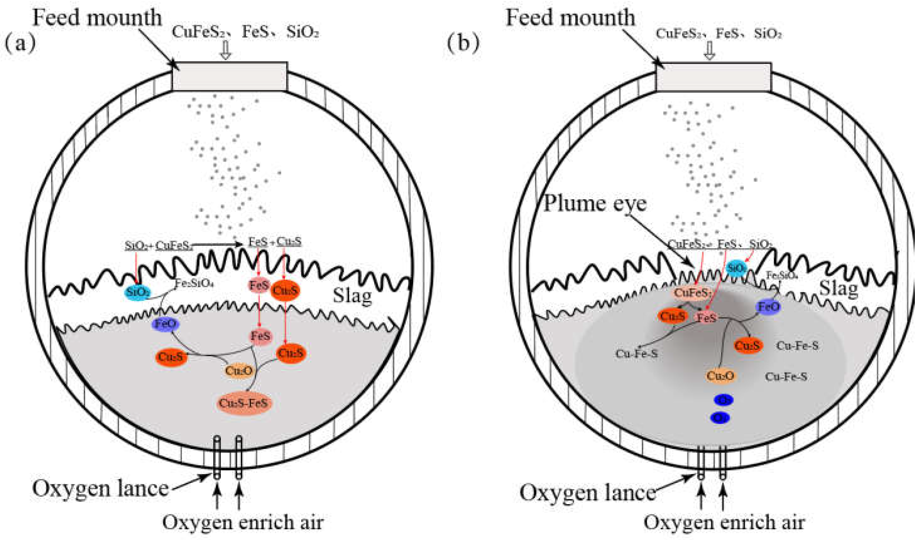
3.2. The Role of Plume Eye in Copper Bottom-Blowing Smelting

The presence of the plume eye in the bottom-blowing smelting furnace plays an important role to enhance the reactions between the feeding materials and oxygen. It can be seen from Figure 1 that the feeding mouth is directly above the lance area in the BBF. Raw materials such as copper concentrate and SiO2 flux can directly fall into the molten bath area with gas injection underneath. The reaction mechanisms with and without a plume eye are discussed below.
Figure 6a shows a schematic diagram of the smelting reaction zone of BBF without a plume eye. If the matte is covered by the slag (without plume eye), the copper concentrate and SiO2 flux fall into the liquid slag. Because the sulfides are immiscible with the slag, which does not contain excess oxygen, the sulfides do not react with the slag directly. The liquid sulfides must pass through the viscus slag layer to enter the matte layer where several phases such as Cu2O, Cu2S, and high-grade matte can react with the concentrate (low-grade matte) to form a final matte. The fine sulfide particles melted to small liquid droplets that require a long time to pass through the slag layer. The SiO2 stays in the slag layer and reacts with liquid slag to form a slag with low Fe/SiO2.
The schematic diagram of the smelting reaction zone of a BBF with a plume eye is shown in Figure 6b. In this case, the copper concentrate as a low-grade matte falls into the plume eye and contacts with the matte directly. The copper concentrate quickly dissolves into the matte and oxidizes further to form the final matte. The “FeO” formed as a result of the oxidation floats up and reacts with the slag and the SiO2 around the plume eye to form the final slag. This reaction mechanism can explain why the splash samples contain different grades of matte, as shown in Table 3. The direct dissolution of copper concentrate into the matte through a plume eye significantly increases the overall reaction rate of the copper-concentrate smelting.

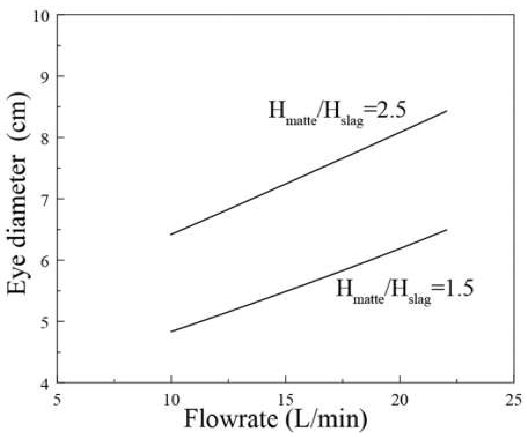
3.3. Effects of Operating Conditions on the Plume Eye Diameter

According to the analyses of the industrial samples combined with the study of the reaction mechanism, a plume eye is confirmed to be present and plays an important role in copper bottom-blowing smelting. Controlling the size of the plume eye will provide useful guidelines for industrial operation. The effects of the gas flowrate rate, slag-layer thickness, and matte-layer thickness on the diameter of the plume eye were studied using water-model experiments. Figure 7a shows the influence of the matte layer thickness on the diameter of the plume eye at a fixed slag-layer thickness of 4 cm. It can be seen from the figure that, at a given gas flowrate, the diameter of the plume eye increases with increasing the ratio of matte thickness to slag thickness. The greater difference in thickness between the matte and the slag, the greater the increase in the diameter of the plume eye. This trend is generally consistent with the results of the steel ladle study [7]. On the other hand, the plume eye diameter increases with increasing the gas flowrate.
Figure 7b shows the influence of slag thickness on the diameter of the plume eye when the thickness of the matte is fixed to 10 cm. At a given gas flowrate, the diameter of the plume eye increases with the ratio of the matte thickness to the slag thickness. However, the increase in the plume eye diameter is not sensitive with a high thickness of the slag layer.
The effect of the gas flowrate on the plume eye diameter is shown in Figure 8 at a fixed ratio of matte thickness to slag thickness. It can be seen that the plume eye diameter is increased linearly with the increase in the gas flowrate at a fixed ratio of water thickness to oil thickness. The gas flowrate per unit area in the laboratory condition is similar to that in the industrial furnace. With a higher-pressure gas injected into the molten bath from the bottom, more dynamic energy will be provided to push the upper layer away.

4. Discussions

In the copper bottom-blowing smelting furnace, raw materials are fed through a feeding port above the lance area. The presence of a plume eye in the lance area enables the feeds to fall directly into the matte through the plume eye causing the reaction mechanism to be different to previous works. Wang et al. [26] proposed a copper-smelting mechanism in an oxygen bottom-blowing furnace. In their mechanism model, the reaction zone of a BBF is divided into seven functional layers from top to bottom, i.e., gas layer, mineral decomposition transitioning layer, slag layer, slag formation transitioning layer, matte formation transitioning layer, weak oxidizing layer, and strong oxidizing layer. The presence of a plume eye in a BBF improves the understanding of the copper-smelting mechanism. The slag layer is not present above the gas injection zone in a bottom-blowing copper-smelting furnace. Therefore, the slag layer, slag formation transitioning layer, and matte formation transitioning layer proposed by Wang et al. [26] need to be removed and a new reaction mechanism is proposed based on the present study.
The copper concentrate as a low-grade matte rapidly dissolves into the oxygen-rich matte in the lance area. A large plume eye can improve the reaction efficiency and increase the productivity of the furnace. This mechanism explained that the productivity of the first BBF was doubled after a few months’ operation [18]. More importantly, with an increased number of copper bottom-blowing smelting furnaces, not all feeding mouths were designed exactly above the gas injection zone. The present study indicates that the location and size of the feeding mouth need to be considered to ensure the raw materials to be dropped directly into the plume eye. The water-model experimental study on the plume eye provides the quantitative effect of different parameters on the size of the plume eye, which will help the copper industry to optimize the operation parameters to control the required plume eye diameter. In the operation of a BBF, the diameter of the plume eye can be increased by increasing the oxygen-enriched air pressure or the thickness of the matte layer. Reducing the thickness of the slag layer can also increase the diameter of the plume eye to a lesser extent. The diameter of the plume eye needs to be adjusted to enable the raw materials from the feeding mouth to be dropped into the matte layer directly as the size of the feeding mouth is fixed.

5. Conclusions

In this study, the existence of plume eyes in a copper bottom-blowing furnace was confirmed by analyzing industrial samples and laboratory water-model experiments. It was found that the splashed samples above the lance zone of the BBF were mainly matte and had a small amount of slag with high SiO2. The grade of the matte in the splashed sample and the Fe/SiO2 ratio of the liquid slag are generally lower than those in the final products. The existence of the plume eye enables the copper concentrate to directly dissolve into the matte, which improves the efficiency of the matte-producing reaction and increases the productivity of the bottom-blowing smelting furnace. The water-model experiments show that, when the thickness of the slag layer is constant, the thicker the matte layer, the larger the diameter of the plume eye. When the thickness of the matte layer is constant, the higher the thickness of the slag layer, the smaller the diameter of the plume eye. The plume eye diameter increases significantly with the increase in the gas flowrate. At a given gas flowrate, the diameter of the plume eye increases with the ratio of the matte thickness to the slag thickness. This research is of great significance for further understanding the strengthening smelting mechanism of the BBF and optimizing the industrial operations.

Author Contributions

Formal analysis, J.L.; resources, B.Z. and K.T.; data curation, J.L.; writing—original draft, J.L.; writing—review & editing, B.Z. and K.T.; supervision, B.Z.; project administration, K.T. and B.Z. All authors have read and agreed to the published version of the manuscript.

Funding

This research received no external funding.

Data Availability Statement

Not applicable.

Acknowledgments

The authors would like to acknowledge Dongying Fangyuan Nonferrous Metals Co., Ltd. for providing the financial support and the industrial samples for this research.

Conflicts of Interest

The authors declare no conflict of interest. The funders had no role in the design of the study; in the collection, analyses, or interpretation of data; in the writing of the manuscript; or in the decision to publish the results.

References

  1. Conejo, A.N.; Feng, W. Ladle Eye Formation Due to Bottom Gas Injection: A Reassessment of Experimental Data. Metall. Mater. Trans. B 2022, 53, 999–1017. [Google Scholar] [CrossRef]
  2. Iguchi, M.; Miyamoto, K.; Yamashita, S.; Iguchi, D.; Zeze, M. Spout eye area in ladle refining process. ISIJ Int. 2004, 44, 636–638. [Google Scholar] [CrossRef]
  3. Krishnapisharody, K.; Irons, G. Modeling of slag eye formation over a metal bath due to gas bubbling. Metall. Trans. B 2006, 37, 763–772. [Google Scholar] [CrossRef]
  4. Chatterjee, S.; Chattopadhyay, K. Formation of slag ‘eye’ in an inert gas shrouded tundish. ISIJ Int. 2015, 55, 1416–1424. [Google Scholar] [CrossRef] [Green Version]
  5. Yonezawa, K.; Schwerdtfeger, K. Spout eyes formed by an emerging gas plume at the surface of a slag-covered metal melt. Metall. Trans. B 1999, 30, 411–418. [Google Scholar] [CrossRef]
  6. Peranandhanthan, M.; Mazumdar, D. Modeling of slag eye area in argon stirred ladles. ISIJ Int. 2010, 50, 1622–1631. [Google Scholar] [CrossRef] [Green Version]
  7. Lv, N.; Wu, L.; Wang, H.; Dong, Y.; Su, C. Size analysis of slag eye formed by gas blowing in ladle refining. JISR Int. 2017, 24, 243–250. [Google Scholar] [CrossRef]
  8. Han, J.; Heo, S.; Kam, D.; You, B.; Pak, J.; Song, H. Transient fluid flow phenomena in a gas stirred liquid bath with top oil layer—Approach by numerical simulation and water model Experiments. ISIJ Int. 2001, 41, 1165–1172. [Google Scholar] [CrossRef] [Green Version]
  9. Mazumdar, D.; Evans, J. Communications: A model for estimating exposed plume eye area in steel refining ladles covered with thin slag. Metall. Trans. B 2004, 35, 400–404. [Google Scholar] [CrossRef]
  10. Zhao, B.; Liao, J. Development of bottom-blowing copper smelting technology: A review. Metals 2022, 12, 190. [Google Scholar] [CrossRef]
  11. Kapusta, J.P.T. Submerged gas jet penetration: A study of bubbling versus jetting and side versus bottom blowing in copper bath smelting. JOM 2017, 69, 970–979. [Google Scholar] [CrossRef]
  12. Chen, M.; Jiang, Y.; Cui, Z.; Wei, C.; Zhao, B. Chemical degradation mechanisms of magnesia–chromite refractories in the copper smelting furnace. JOM 2018, 70, 2443–2448. [Google Scholar] [CrossRef]
  13. Xu, L.; Chen, M.; Wang, N.; Gao, S. Chemical wear mechanism of magnesia-chromite refractory for an oxygen bottom-blowing copper-smelting furnace: A post-mortem analysis. Ceram. Int. 2021, 47, 2908–2915. [Google Scholar] [CrossRef]
  14. Chen, M.; Cui, Z.; Zhao, B. Slag Chemistry of Bottom Blowing Copper Smelting Furnace at Dongying Fangyuan. In Proceedings of the 6th International Symposium on High-Temperature Metallurgical Processing, Orlando, FL, USA, 15–19 March 2015; pp. 257–264. [Google Scholar]
  15. Liang, S. A review of oxygen bottom blowing process for copper smelting and converting. In Proceedings of the 9th International Copper Conference (Copper 2016), Kobe, Japan, 13–16 November 2016; pp. 1008–1014. [Google Scholar]
  16. He, S.; Li, D. Discussion on issues related to Shuikoushan Copper Smelting process. China Nonferrous Metall. 2005, 34, 19–22. (In Chinese) [Google Scholar]
  17. Chen, Z. The application of oxygen bottom-blowing bath smelting of copper. China Nonferrous Metall. 2009, 5, 16–22. (In Chinese) [Google Scholar]
  18. Liang, S.; Chen, Z. Application and development of oxygen enriched bottom-blowing copper smelting technology furnace. Energy Sav. Nonferr. Metall. 2013, 4, 16–19. (In Chinese) [Google Scholar]
  19. Cui, Z.; Wang, Z.; Zhao, B. Features of the bottom blowing oxygen copper smelting technology. In Proceedings of the 4th International Symposium on High-Temperature Metallurgical Processing, San Antonio, TX, USA, 3–7 March 2013; pp. 351–360. [Google Scholar]
  20. Zhao, B.; Cui, Z.; Wang, Z. A new copper smelting technology—Bottom blowing oxygen furnace developed at Dongying Fangyuan Nonferrous Metals. In Proceedings of the 4th International Symposium on High-Temperature Metallurgical Processing, San Antonio, TX, USA, 3–7 March 2013; pp. 3–10. [Google Scholar]
  21. Qu, S.; Li, T.; Dong, Z.; Luan, H. Plant practice of and design discussion on oxygen enriched bottom blowing smelting. Nonferrous Met. Extr. Metall. 2012, 3, 10–13. (In Chinese) [Google Scholar]
  22. Du, X.; Zhao, G.; Wang, H. Industrial application of oxygen bottom-blowing copper smelting technology. China Nonferrous Metall. 2018, 4, 4–6. (In Chinese) [Google Scholar]
  23. Wang, H.; Yuan, J.; He, R.; Wang, X. Plant practice of copper oxygen enrichment bottom blowing smelting. Nonferrous Met. Extr. Metall. 2013, 10, 15–19. (In Chinese) [Google Scholar]
  24. Yan, J. Recent operation of the oxygen bottom-blowing copper smelting and continuous copper converting technologies. In Proceedings of the 9th International Copper Conference (Copper 2016), Kobe, Japan, 13–16 November 2016; pp. 13–16. [Google Scholar]
  25. Song, K.; Jokilaakso, A. Transport phenomena in copper bath smelting and converting processes–A review of experimental and modeling studies. Miner. Process. Extr. Metall. Rev. 2020, 42, 107–121. [Google Scholar]
  26. Wang, Q.; Guo, X.; Tian, Q. Copper smelting mechanism in oxygen bottom-blowing furnace. Trans. Nonferrous Met. Soc. China 2017, 27, 946–953. [Google Scholar] [CrossRef]
  27. Jiang, X.; Cui, Z.; Chen, M.; Zhao, B. Study of plume eye in the copper bottom blowing smelting furnace. Metall. Trans. B 2019, 50, 782–789. [Google Scholar] [CrossRef]
  28. Shui, L.; Cui, Z.; Ma, X.; Rhamdhani, M.A.; Nguyen, A.; Zhao, B. Mixing phenomena in a bottom blowing copper smelter: A water model study. Metall. Trans. B 2015, 46, 1218–1225. [Google Scholar] [CrossRef]
  29. Liao, J.; Liao, C.; Zhao, B. Comparison of copper smelting slags between flash smelting furnace and bottom-Blowing furnace. In 12th International Symposium on High-Temperature Metallurgical Processing; Springer: Cham, Switzerland, 2022; pp. 249–259. [Google Scholar]
Figure 1. Schematic diagram of oxygen bottom-blowing smelting furnace.
Metals 13 00217 g001
Figure 2. Schematic diagram of water model experiment: (a) front view; (b) side view.
Metals 13 00217 g002
Figure 3. Schematic diagram of measuring the diameter of “plume eye”.
Metals 13 00217 g003
Figure 4. Typical microstructure of a quenched oxygen bottom-blowing slag.
Metals 13 00217 g004
Figure 5. Typical microstructures of the splash samples. (a) Sample 1#, (b) Sample 2#, and (c) Sample 3#.
Metals 13 00217 g005
Figure 6. Schematic diagram of smelting reaction zone of oxygen-enriched bottom-blowing furnace (a) without “plume eye” and (b) with “plume eye”.
Metals 13 00217 g006
Figure 7. Effect of matte-to-slag ratio on plume eye diameter under different gas flow, (a) fixed slag thickness 4 cm and (b) fixed matte thickness 10 cm.
Metals 13 00217 g007
Figure 8. Effect of gas flowrate on the diameter of plume eye at fixed matte-thickness-to-slag-thickness ratio.
Metals 13 00217 g008
Table 1. Phase compositions of oxygen bottom-blowing copper-smelting slag measured by EPMA.
Phase“FeO”Cu2OCaOSiO2Al2O3As2O3MgOSPbOZnOMoO3K2OFe/SiO2
Spinel94.50.00.00.42.80.00.30.00.01.50.10.0
Slag56.90.21.132.14.10.10.80.00.62.50.21.41.38
PhaseFeCuSAs2O3PbOZnOMoO3
Matte2.470.121.70.10.10.10.5
Table 2. Phase compositions of liquid slag, spinel, and SiO2 in the splashed samples measured using EPMA.
SamplePhaseComposition (wt.%)
FeOCu2OCaOSiO2Al2O3As2O3MgOSPbOZnOMoO3K2OFe/SiO2
1#spinel92.80.100.54.100.3001.30.20-
liquid57.20.41.231.34.20.10.70.10.42.50.31.31.42
2#spinel92.90.100.53.900.300.11.500-
liquid48.61.61.438.14.10.210.30.52.50.21.50.99
3#SiO24.80.50.293.20.400.200.10.20.10.3-
liquid47.50.41.7404.10.21.10.10.52.80.21.30.92
Table 3. Matte compositions in the splash samples measured using EPMA.
SamplePhaseComposition (wt.%)
FeCuSAsPbZnMo
1#matte2.270.422.50.00.10.10.2
2#matte 12.270.621.90.000.00.2
matte 25.964.221.40.20.70.10.1
3#matte4.566.624.200.00.10.2
Disclaimer/Publisher’s Note: The statements, opinions and data contained in all publications are solely those of the individual author(s) and contributor(s) and not of MDPI and/or the editor(s). MDPI and/or the editor(s) disclaim responsibility for any injury to people or property resulting from any ideas, methods, instructions or products referred to in the content.

