Article

Study on the Effect of Pulse Waveform Parameters on Droplet Transition, Dynamic Behavior of Weld Pool, and Weld Microstructure in P-GMAW

1
College of Electronic and Information Engineering, Nanjing University of Aeronautics and Astronautics, Nanjing 210016, China
2
College of Aeronautical Engineering, Nanjing Vocational University of Industry Technology, Nanjing 210023, China
*
Authors to whom correspondence should be addressed.
Metals 2023, 13(2), 199; https://doi.org/10.3390/met13020199
Submission received: 2 December 2022 / Revised: 6 January 2023 / Accepted: 11 January 2023 / Published: 19 January 2023
(This article belongs to the Special Issue Special Metal-Alloy Coating and Catalysis)

Abstract

:
The heating and impact of arc and droplet acting on the weld pool lead to the transfer of mass, heat, and momentum, which affects the dynamic behavior of the weld pool and the microstructure in the P-GMAW process. In this paper, an image processing program is used to extract the dynamic behavior characteristics of the droplet transition and the weld pool in high-speed photography. The influence of the current waveform on the arc pressure and the impact of the droplet is quantitatively analyzed with different parameters. The dynamic behavior of the weld pool and the microstructure under different current waveform conditions are further studied. The internal relation of current waveform parameters to weld pool behavior and weld microstructure was expounded. The results show that the droplet impact is positively correlated with the pulse peak current. The rectangular wave pulse has a more significant droplet impact than the exponential wave with the same waveform parameters. The impact of droplet transition on the weld pool enhances the convective intensity of the weld pool. It slows down the cooling rate of the solidified weld microstructure below the tail of the weld pool, increasing the grain size of the weld microstructure.

1. Introduction

The pulsed gas metal arc welding process (P-GMAW) is widely used in automated welding, which realizes the control of droplet transfer while ensuring welding efficiency. With the requirement for high welding quality in aerospace, transportation, and pressure vessel fields, the minute control of the welding process has become a new requirement of the manufacturing industry following the control of the droplet transfer process [1,2]. The microstructure of the weld is the dominant factor that affects the quality of the weld joint while ensuring the stability of the droplet transfer process [3,4]. The minute control of the welding process cannot be achieved only by optimizing the droplet transfer process. Many studies have shown that the weld pool’s dynamic behavior affects the weld pool’s solidification process and weld structure [5,6]. Therefore, the research on the dynamic behavior of the P-GMAW weld pool is of great significance to realizing minute control of the welding process. However, the mechanism of the influence of the P-GMAW current waveform on the dynamic behavior of the weld pool and the structure of the weld is still unclear, which hinders the further development of the P-GMAW.
The study of arc shape and droplet transition behavior under different waveform parameters of P-GMAW has important practical significance for optimizing pulse waveform. The drop transition forms in P-GMAW are mainly divided into three types: more drop in one pulse, one drop in one pulse, and one drop in more pulse, in which the transition form of one drop in more pulse is unstable and prone to short circuit resulting in splashes; while the weld of more drop in one pulse has finger-like penetration depth, which is easy to cause cracks. Many studies have proved that one drop in a vein is the best transition mode of droplet melting [7,8]. The current pulse waveform also affects the welding wire and weld pool’s heat and mass transfer process. Existing studies have shown a strong correlation between the momentum carried by droplets when they impact the weld pool and the weld penetration depth [9,10]. In literature, the concept of compelling momentum in the droplet transition process was introduced and defined as the ratio of the total momentum carried by the droplet in unit time to the welding speed, which could better characterize the influence of the droplet speed on the weld depth. The adjustment of the current waveform significantly affects the heat transfer process acting on the weld pool and the cooling time of the welded joint. While controlling the welding heat input, the current waveform also changes the heat conduction process [2], significantly affecting the weld pool’s solidification process and the weld microstructure [7]. Many studies have shown that the P-GMAW welding process can adjust the weld metal structure by adjusting the pulse frequency and droplet impact strength [11,12]. The impact of the current pulse acting on the weld pool will lead to the breakage of trace solidified dendrites and the presence of equiaxial grains in the molten pool, which are conducive to the nucleation of dendrites and grow into equiaxial primary phase, and finally, define the weld structure.
A large number of research results have been obtained on the droplet transition process and arc of the P-GMAW process, but research on the current waveform is only limited to the droplet transition process. More research on the influence mechanism of the current waveform on the dynamic behavior of weld pool and weld microstructure could be learned. In summary, existing research has the following deficiencies:
(1)
Existing studies have analyzed the influence of current waveforms on droplet transition behavior. However, there is no quantitative analysis of the heat input and impact of arc and droplet transition acting on the weld pool surface, so the differences in heat and force effects on the weld pool under different current waveforms cannot be quantitatively compared.
(2)
The influence of P-GMAW current waveform on weld pool oscillation behavior, the solidification process of weld pool, and weld microstructure are rarely studied and reported systematically.
In this paper, for the P-GMAW, the effect of the current waveform on the heat and force acting on the weld pool, the weld pool behavior, the weld microstructure, and properties are based on the welding high-speed photography system and image processing system.
This paper quantitatively analyzed the differences in heat, force action, and dynamic behavior of weld pools under different pulse peak currents and pulse waveform shapes based on the self-developed high-speed welding photography platform and image processing system. At the same time, combined with the flow behavior of the weld pool, the influence of the current waveform on the solidification process of the weld pool and the weld microstructure was revealed in order to study the influence of the current waveform on the dynamic behavior of the weld pool and the weld microstructure of the P-GMAW process systematically.

2. Materials and Methods

The welding high-speed photography system used in this paper is shown in Figure 1. In order to capture images of the weld pool from different angles, the high-speed camera shot the welding area from two angles: highspeed camera 1 was placed horizontally, and the arc morphology, droplet transition process, and the profile of the upper surface of the molten pool could be observed. Highspeed camera 2 was used to observe the flow behavior of the weld pool surface. The high-speed camera is fixed relative to the welding torch, and the shooting direction is perpendicular to the weld. The electrical signal acquisition system in the welding process is composed of a current Hall sensor (model AKHC-EKAA DC), a voltage Hall sensor (model KCE-VZ01), and a signal acquisition card (model NI 6251, collection frequency 5 × 10⁵ Hz).
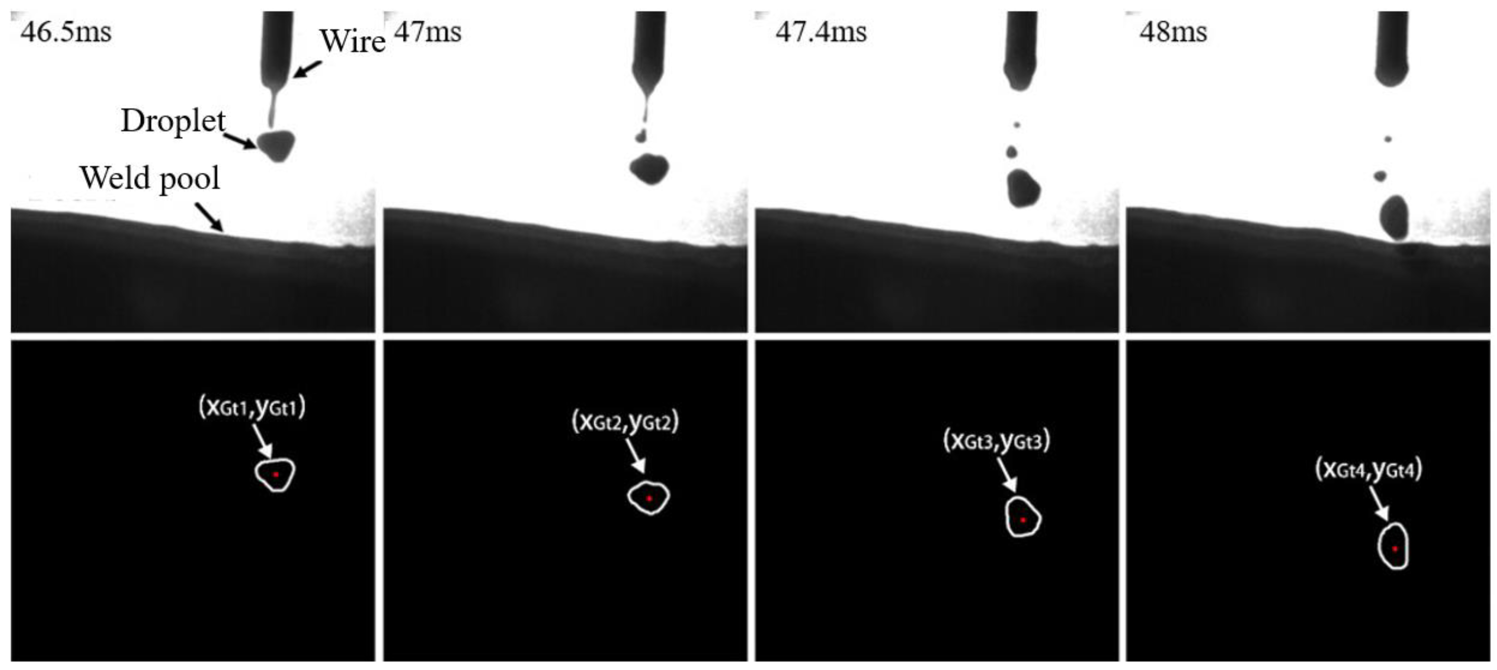
The wavelength of the laser source 1 is 850 nm, and the 850 nm narrow-band filter is attached to the high-speed camera 1. After the software processing of the high-speed photography pictures taken by highspeed camera 1, the contour coordinates of the molten droplets and weld pools in the pictures can be obtained, as shown in Figure 1.
In P-GMAW, alloying elements such as silicon and manganese in the base metal and the wire had a high affinity to react with oxygen and form silicon oxide and manganese oxide. These oxides accumulate on the surface of the weld pool and form slag [13]. The slags have a lower density than the molten metal and follow the flow pattern of the weld pool; hence, the slag flow pattern and accumulation location can disclose the weld pool flow behavior [14]. The torch angle of highspeed camera 2 is 60°. In order to capture the outline of slags (the oxide on the surface of weld pool) and avoid the interference of arc light, the laser source and narrowband filter with a wavelength of 650 nm was selected to highlight the outline information of slags on the weld pool, as shown in Figure 1.
In order to study the influence of pulse current waveform parameters on droplet size and droplet velocity, the center of gravity, diameter, and droplet velocity of the droplet should be measured by image processing technology. A rectangular coordinate system can be set up according to the arrangement of pixels on the high-speed photography image. The x-axis is the bottom edge of the image, the direction is left, the y-axis is the left side of the image, and the direction is up. Since the welding gun and wire are perpendicular to the workpiece surface, and the camera lens is perpendicular to the weld, the speed of the dropper perpendicular to the picture surface (in the z-dimension direction) can be ignored. Due to the effect of surface tension on the droplet, the droplet will approximate into a sphere. For convenient analysis and calculation, the droplet is regarded as a sphere. In addition, the size of the picture taken by the high-speed camera is 480 × 428, and the diameter of the welding wire is 1.2 mm. The pixel size can be quantified by measuring the diameter of the welding wire in the picture while maintaining the position of the camera and torch. The extraction process is as follows:
(1) The contours and positions of the droplets at different times during the welding process were extracted, as shown in Figure 1. The droplet area (Sdroplet), the coordinates of droplet center of gravity (XGt, YGt), and droplet diameter (Ddroplet) were calculated based on the contour coordinates of the droplet, as shown in Equations (1)–(3).
S d r o p l e t = x = x m i n x m a x ( y m a x y min )
( x G t , y G t ) = ( 1 n x n t n , 1 n y n t n )
D d r o p l e t = 4 × S d r o p l e t π
where (Xnt, Ynt) is all coordinates of the droplet contour in Figure 1, (Xmax, Ymax) is the maximum coordinate value of the droplet contour, (Xmin, Ymin) is the minimum coordinate value of the droplet contour, and n is the number of droplet contour points. Sdroplet is the area of the droplet in high-speed photography and Ddroplet is the equivalent diameter of the droplet.
(2) The coordinates of the center of gravity position of the droplet are continuously collected, as shown in Figure 2. The droplet velocity is calculated according to Equation (4), and the droplet momentum is calculated according to Equation (5).
V d r o p l e t = ( x G t 1 x G t 2 ) 2 + ( y G t 1 y G t 2 ) 2 | t 2 t 1 |
M d r o p l e t = π D d r o p l e t 3 6 ρ V d r o p l e t
where Vdroplet is the velocity of the droplet, ρ is the density of the liquid metal, and Pdroplet is the momentum of the droplet.
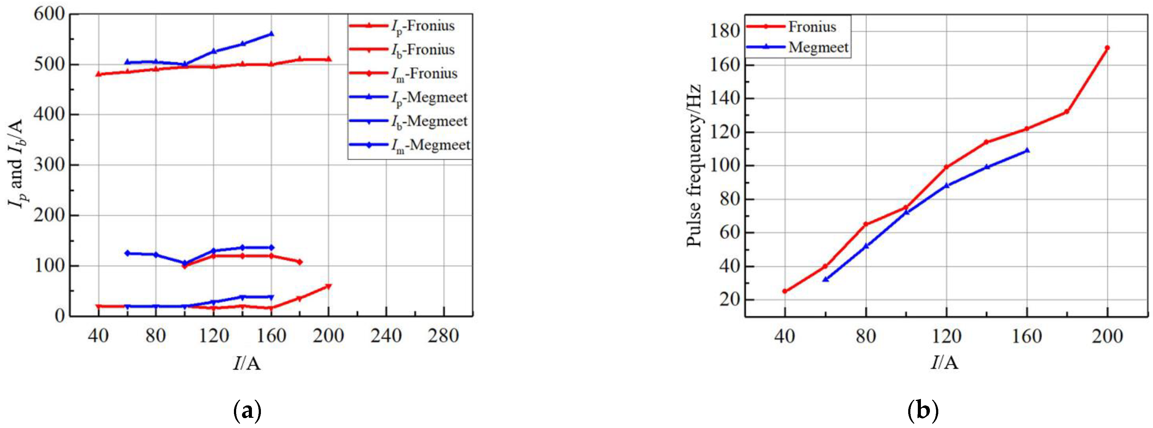
In this paper, Fronius TPS5000 and Megmeet PM500A were selected as power sources of the welding system to provide the needed waveform. Fronius TPS5000 is used to provide a trapezoidal pulse waveform, and Megmeet PM500A is used to provide an exponential pulse waveform. The pulse waveform parameters are automatically set by the unified control system of the welding power source according to the welding current, as shown in Figure 3. Ip is peak pulse current, Ib is Pulse base value current, and Im is mean current. In order to ensure the stability of one pulse and one drop, the pulse width provided by both welding power sources is 4 ms.
The Ip of the trapezoidal pulse waveform supplied from a Fronius TPS5000 can be independently adjusted. We used 4 mm Q235 low carbon steel and 1.2 mm ER50-6 carbon steel wire, respectively, as the base metal and welding wire. The shielding gas is 82% Ar + 18% CO2 mixture, and the gas flow rate is 20 L/min. The welding speed with I = 60 A is 25 cm/min, the welding speed with I = 100 A is 38.5 cm/min. The process parameters are shown in Table 1. The other pulse waveform parameters were automatically set by the unified control system of the welding power supply according to the welding current.
The arc heat and the heat carried by the droplet are the main heat source of the weld pool in P-GMAW. It is assumed that the current density is evenly distributed on the projection surface of the arc and weld pool. The arc heat ( E a r c p u l s e ) acting on the weld pool during a single current pulse is shown in Equation (6), and the heat carried by the molten droplet ( E d r o p l e t p u l s e ) is shown in Equation (7). The total energy input ( E t o t a l p u l s e ) on the surface of the molten pool for a single pulse cycle is shown in Equation (8), and the energy input power ( P t o t a l p u l s e ) on the surface of the molten pool is shown in Equation (9).
E a r c p u l s e = 0 1 / f P a r c d t = 0 1 / f I ( V w φ ) d t
E d r o p l e t p u l s e = ρ 4 3 π ( D d 2 ) 3 300 2500 C p d T
E t o t a l p u l s e = ρ 4 3 π ( D d 2 ) 3 300 2500 C p d T + 0 1 / f I ( V w φ ) d t
P t o t a l p u l s e = E t o t a l p u l s e × f
where f is the pulse current frequency; Vw is the cathode pressure drop, which is 16.7 V [8]; φ is the electron escape work of the base metal, which is 4.77 V [10]; ρ is the density of the liquid metal, Dd is the equivalent diameter of the molten droplet, Cp is the specific heat capacity of the liquid metal, and T is the molten drop temperature, assumed to be 2500 °C.
The arc force acting on the weld pool ( p a r c )   during P-GMAW welding is shown in Equation (10), and the equivalent pressure ( p d r o p l e t ) of the droplet impact on the weld pool is shown in Equation (11).
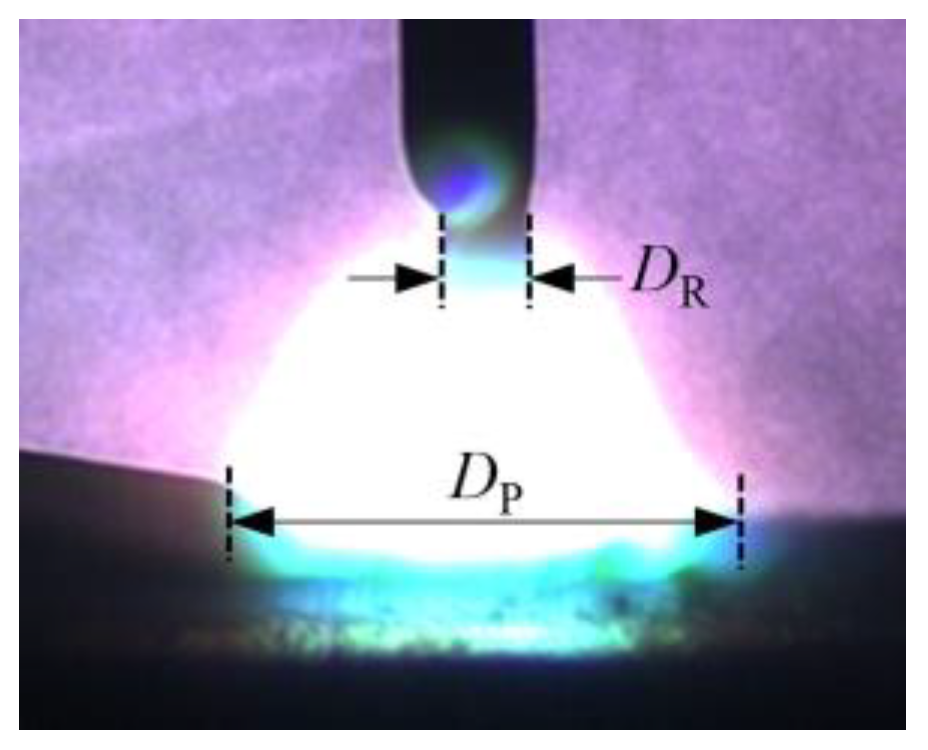
p a r c = μ 4 π I 2 log ( D P D R ) / π D p 2 4
p d r o p l e t = M d r o p l e t f / π D d 2 4 = 2 D d ρ V d f 3
where μ is the spatial permeability, μ = 1.26 × 10⁻⁶ N/A2; ρ   is the density of the liquid metal, ρ = 7.85 g/cm3; f is the pulse frequency, f = 40 Hz; Vd is the droplet velocity; Dd is the droplet equivalent diameter; DP is the projected diameter of arc on the weld pool. DR is the diameter of the arc root. The dimension parameters of the arc in the welding process are shown in Figure 4.

3. Results and Discussion

3.1. Effect of Current Waveform on Heat and Force Acting on Welding Pool

3.1.1. Effect of Ip on Heat and Force Acting on Welding Pool

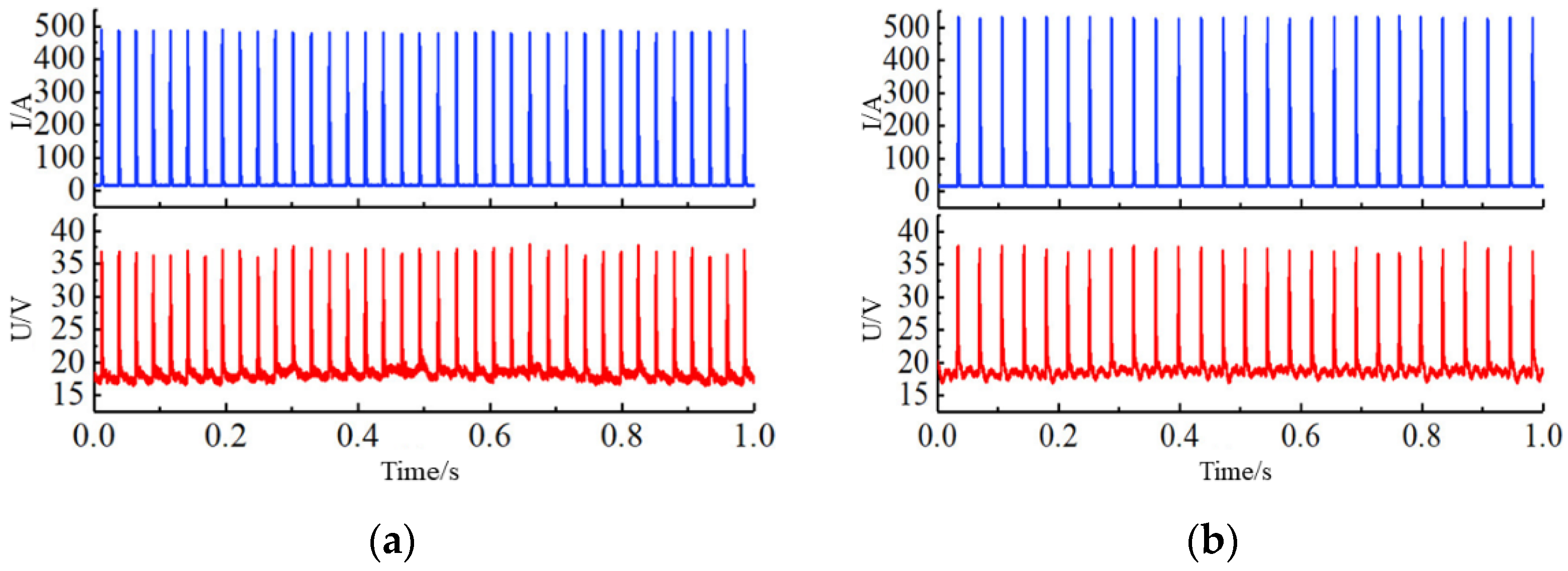
The current waveform of the P-GMAW process is periodic, and the thermal and force effects on the welding pool during the whole welding process can be analyzed by studying the droplet and arc behavior in a single pulse period. Figure 5a,b are the current and voltage waveforms with Ip of 485 A and 525 A, respectively, and the welding current is both 60 A.
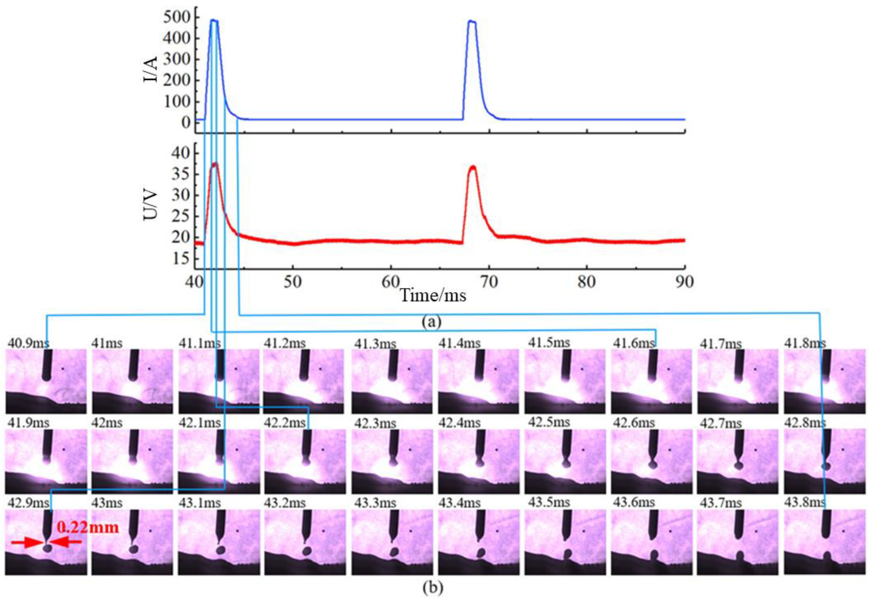
Figure 6 and Figure 7 show the high-speed photography of the arc and droplet transition process and synchronous welding electrical signals within a single current pulse period with the parameters of Ip = 485 A and Ip = 525 A, respectively. It can be found that the arc size increases and the arc brightness increases at the peak pulse stage, and the welding wire melts rapidly under the action of arc heat and forms a molten droplet hanging at the end of the wire. In the late pulse peak stage, the molten droplet falls off, and the current at the pulse base value stage falls back to the base value. The function of the current at the base value is to maintain the arc, which is 20 A, and the arc is almost invisible. In the whole pulse period, there was no obvious melting at the end of the wire at the base value stage.
The increase of Ip lead to the decrease of pulse frequency with the same average current (under the condition of 60 A welding current, Ip = 485 A, f = 40 Hz, Ip = 525 A, f = 30 Hz), and higher Ip accelerate the melting droplet from the welding wire. As shown in Figure 6 and Figure 7, it takes 2 ms from the beginning of the pulse to the moment when the droplet is released from the wire with Ip = 485 A, and the shrinking neck diameter before the droplet is 0.22 mm, while it takes 1.6 ms with Ip = 525 A, and the shrinking neck diameter before the droplet is 0.33 mm. The results show that with the higher Ip, the shorter the time it takes, and the larger the diameter of the shrinking neck as the droplet to detangle from the wire.
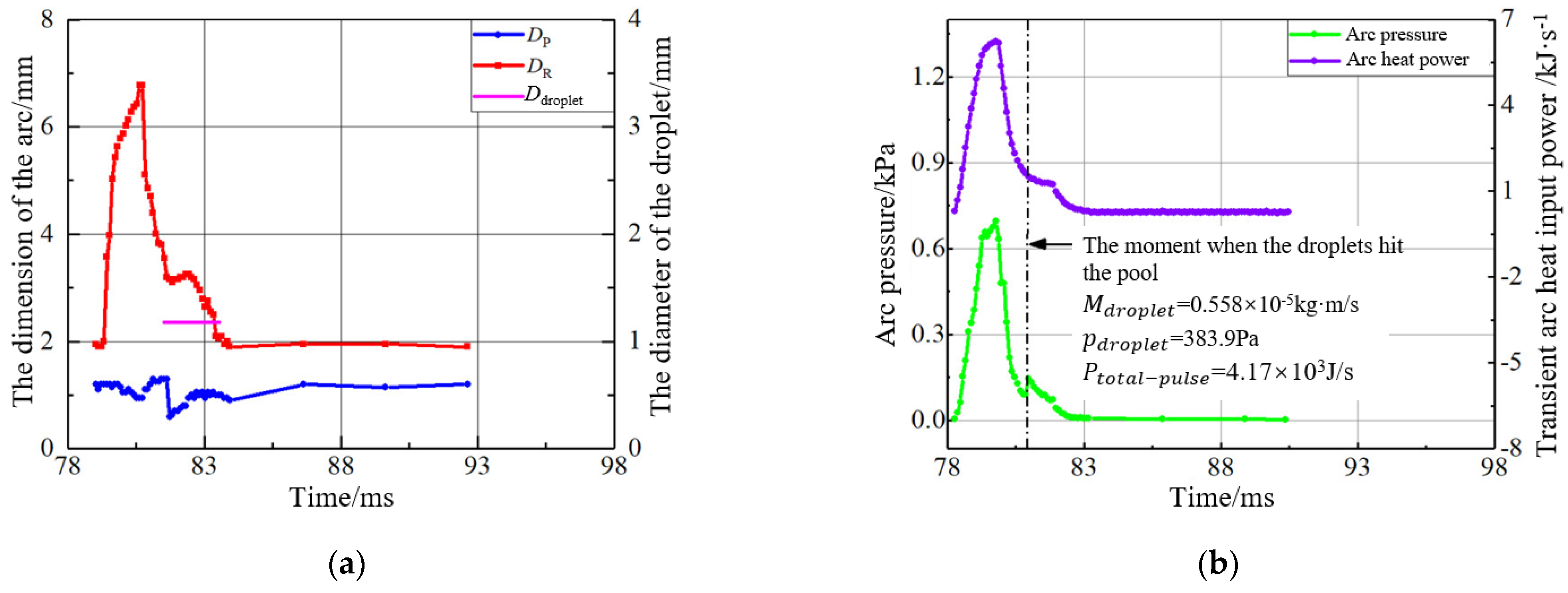
Figure 8a shows the droplet and arc size at different times during a single pulse period (Ip = 485 A). The change process of heat and force acting on the weld pool can be calculated by combining Equations (6) and (11) with the current and voltage data in Figure 4, as shown in Figure 8b. The DP is synchronized with the current, however, at the moment when the droplet detaches from the wire, a peak occurs in the DP curve, which is due to the increase of metal vapor concentration in the arc space resulting from by the droplet detaching from the wire. The DR Curve first falls and then rises at the peak pulse stage because the arc root is always located at the shrink neck between the welding wire and the droplet. The droplet gradually grows and forms a shrink neck, and the size of the arc root decreases gradually. As the droplet detaches, the shrink neck disappears, and the size of the arc root increases. The arc thermal power also has the same variation trend as the current curve, as shown in Figure 8b. The arc pressure increases rapidly with the rise of the current and presents a brief stable stage similar to the current waveform after reaching the peak value. The peak arc pressure is nearly 580 Pa. With the current falling to the base value, the arc pressure falls back and maintains at nearly 5 Pa. The impact of the droplet acting on the weld pool at a fixed frequency can be equivalent to equivalent force, as shown in Equation (11). However, the solidification process of the weld pool is a phase transition process of rapid cooling, and the equivalent force cannot accurately measure the effect of a single molten droplet impacting on the weld pool. Therefore, the momentum carried by a single molten drop is another major parameter to measure the impact. When Ip = 485 A, the projection area of the droplet is 1.1 mm2, the velocity of the droplet is 1.09 m/s, the momentum carried by the droplet is 0.69 × 10⁻⁵ kg·m/s, and the equivalent pressure of the droplet impact on the weld pool is 251 Pa. The welding heat input power is 2.41 × 10³ J/s.
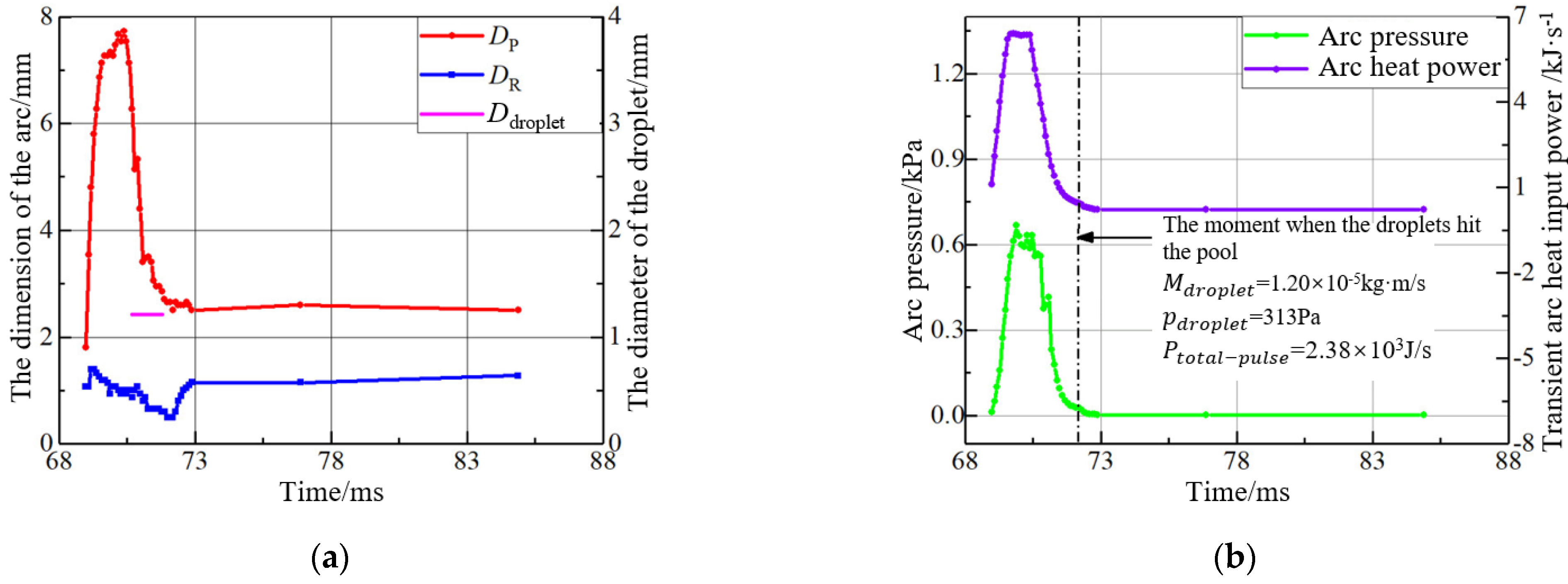
Figure 9 shows the size of the molten droplet and arc and the thermal and force effects on the weld pool with the Ip = 525 A. The arc size increased significantly as the peak pulse current increased, and the arc pressure was maintained at about 610 Pa during the peak pulse phase, which was significantly higher than the peak pulse pressure with the Ip = 485 A, the projected area of the droplet is 1.15 mm2, and the velocity is 1.65 m/s. Due to the increase of heat input in the peak phase of the pulse, the size and velocity of the droplet increase simultaneously, which leads to the rise of the droplet momentum. According to the calculation, As Ip increased to 525 A, the momentum carried by the droplet increased to 1.20 × 10⁻⁵ kg·m/s, and the equivalent impact force of the droplet acting on the weld pool is 313 Pa. At the same time, a too-high pulse peak current could increase the volume of residual droplets at the end of the welding wire, which can easily lead to the occurrence of multi drop during one pulse, as shown in Figure 10. Higher Ip increases the energy input of a single current pulse, while reducing the pulse frequency, resulting in no significant change in the total heat input power during the welding process. According to the measurement, the total heat input power received by the weld pool as the Ip is 525 A is 2.38 × 10³ J/s, which is approximately it as the Ip is 485 A.
Figure 11 shows the influence of pulse peak current on arc pressure, droplet momentum, and equivalent impact force when the welding current is equal to 60 A. It can be found that with the increase of Ip, the equivalent impact force and arc pressure of the molten drop rise slowly, but the momentum of the molten droplet increases significantly (when Ip increases from 485 A to 525 A, the momentum of the molten droplet rises nearly 200%).
At the peak of the pulse, the electromagnetic contraction force generated by the current passing through the droplet is one of the leading forces driving the droplet off the wire, which affects the initial velocity of the droplet when it leaves the wire [15]. At the same time, the metal flow of the molten droplet at the end of the welding wire will produce a downward force F m f , which could increase the initial velocity of the droplet [16]. The droplet accelerates under the impact of the high-speed plasma current in the arc space after the droplet disconnects from the wire and enters the arc space [17]. The downward force F m f and the axial force F a on the molten droplet in the arc space increase with the current increase [15,16,17]. It can be proved that the force received by the molten drop is higher before it disconnects from the wire as the Ip increase, which explains that the higher the peak pulse current, the shorter the time taken for the molten droplet to disconnect from the wire, and the larger the diameter of the shrinking neck before disconnecting. At the same time, according to references [15,16,17], higher Ip could lead to a more significant initial velocity of the molten droplet when it breaks away from the welding wire. At the same time, it will be affected by more intense plasma impact in the arc space, and the acceleration of the molten droplet will increase, leading to the increase of the momentum of the molten droplet. Due to the decrease of in pulse frequency, the increase of droplet impact force is slower than that of droplet momentum, which leads to the equivalent force of droplet impact is significantly smaller than that of arc pressure. However, the difference in the impact form of the arc and droplet on the weld pool does not mean that the impact of the droplet on the weld pool is much smaller than that of the arc. At the same time, it has been shown that the arc force at the peak of the pulse cannot significantly change the surface state of the weld pool. The impact of the molten droplets is the main factor causing the oscillation behavior of the weld pool [18]. However, Ip is positively correlated with the impact of the weld pool.

3.1.2. Effect of Waveform Shape on Heat and Force Acting on Welding Pool

Due to the high coupling between welding parameters and pulse waveform parameters, there is no apparent linear relationship between waveform parameters of one pulse and one drop under different current conditions. Therefore, many welding power supply manufacturers have established welding parameter libraries to ensure the stability of one pulse and one drop, which leads to differences in pulse waveforms under the same current. When the welding current is between 100 A and 180 A, the preset pulse waveform of the FroniusTPS5000 changes from trapezoid to posterior median trapezoid. The preset pulse waveform of the Megmeet PM500A is the posterior median exponential pulse at the full range of welding currents. Many scholars have thoroughly studied the effect of the posterior median parameters of the pulse current waveform on the melting droplet transition process [19]. The results show that the central role of the posterior median pulse is to supplement the pulse’s peak phase energy and increase the pulse-drop transition’s stability [19]. Therefore, this section will not analyze the effect of the median current after the pulse on the melt transition process.
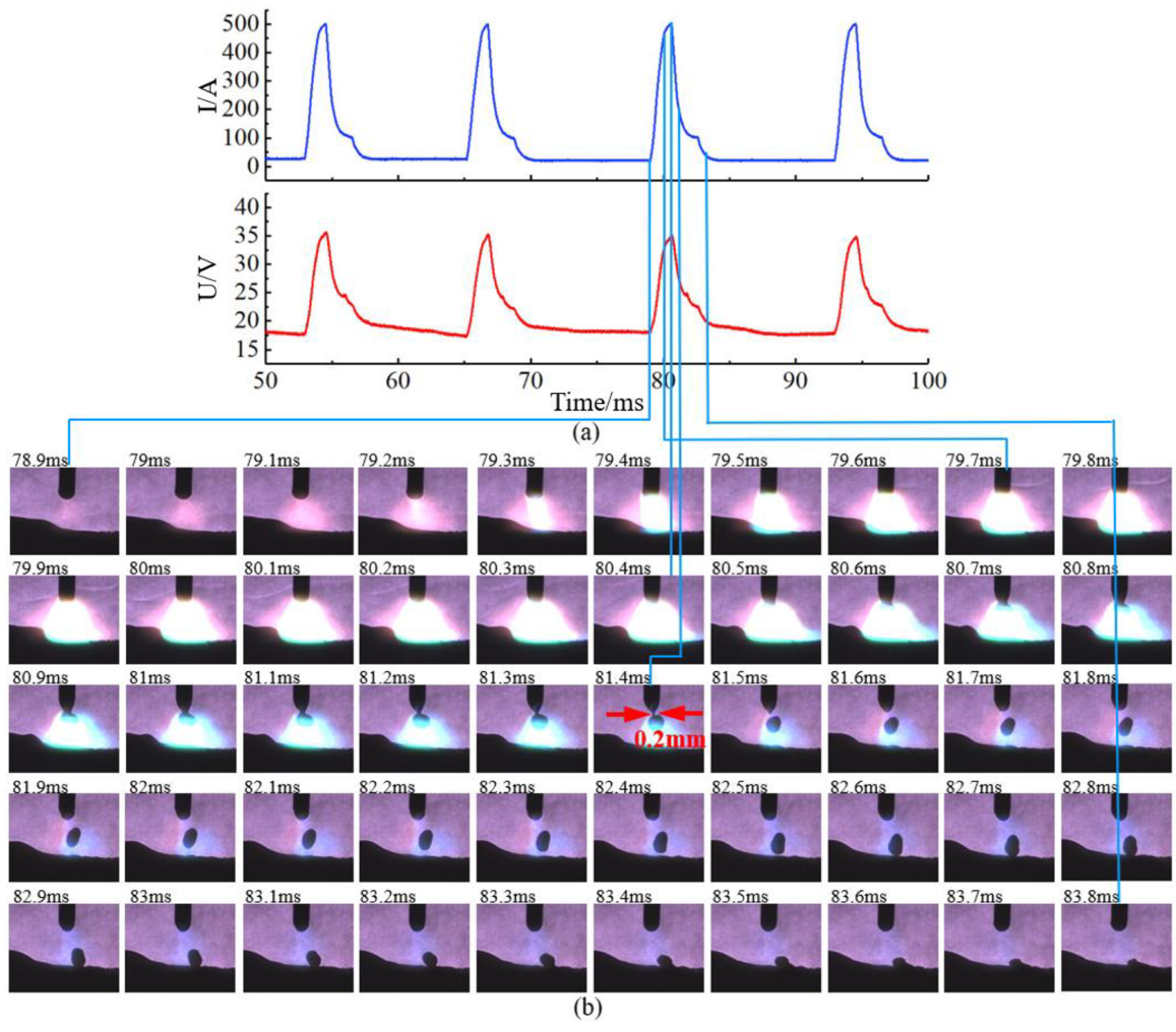
In order to avoid the influence of the difference in pulse waveform parameters with a different welding power source, this section carries out the test at the intersection point of the process parameters of the two pulse waveforms. When the welding current is 100 A, the trapezoid wave parameters (Ip = 500 A; Ib = 17 A; Im = 100 A; f = 75 Hz) are similar to exponential wave parameters (Ip = 500 A; Ib = 20 A; Im = 100 A; f = 73 Hz), as shown in Figure 3. The arc and droplet transition behavior of trapezoidal pulse and exponential pulse are shown in Figure 12 and Figure 13.
The pulse onset time of the trapezoid pulse waveform was 185.9 ms, and the droplet detachment time was 187.7 ms. The time from the pulse onset time to the moment of droplet detachment from the wire was 1.8 ms, and the diameter of droplet retraction before detachment from the wire was 0.35 mm. The onset time of the exponential pulse waveform was 78.9 ms, the time of droplet detachment was 81.5 ms, the time of droplet detachment was 2.6 ms, and the diameter of the shrinking neck before droplet detachment was 0.22 mm. It took longer for the droplet of the exponential pulse to leave the wire than that of the trapezoidal pulse, and the diameter of the shrinking neck before the droplet leaving the wire was significantly smaller.
Under the same pulse peak current, the droplet in the arc space of the trapezoidal pulse was significantly compressed, while the droplet of the exponential pulse had no obvious deformation. The reason for the above differences is that the current rises quickly at the initial stage of the trapezoid pulse and the metal vapor concentration in the arc space is relatively small, forcing the arc to climb to the upper end of the melt drop, and the electromagnetic contraction force rises faster, as shown in Figure 12b 187.2–187.8 ms, which further enhances the extrusion effect of the electromagnetic contraction force on the constricted neck, and the melt drop is easy to break off the welding wire. The slow rise rate of the exponential pulse waveform current leads to a relatively sufficient metal vapor in the arc space, which allows a larger current to pass through the bottom of the melt drop, resulting in the arc concentrated below the melt drop and did not climb to the position of the shrinking neck, which to a certain extent prevents the separation of the melt drop, as shown in Figure 13b 80.8–81.5 ms. The above phenomena are similar to the results obtained by Hertel through simulation [20].
The droplet projection size of the trapezoidal pulse waveform was 1.156 mm2, and the velocity was 1.28 m/s. The droplet projection size of the exponential pulse waveform was 1.09 mm2, and the velocity was 0.82 m/s. Previous studies have proven that the increase of Ip could lead to the simultaneous increase of electromagnetic force and high-speed convection intensity in the droplet and then increase the initial velocity of the droplet [20]. Under the same Ip condition, the trapezoid pulse takes less time for the droplet to detach from the wire. The current is 300 A when the droplet detangles from the wire of the trapezoid pulse, which is significantly higher than that of the exponential pulse (the current is around 200 A when the droplet detaches from the wire), which results in a stronger driving effect on the arc of the trapezoid pulse after the droplet detangles from the wire (as shown in Equation (14)). As a result, the droplet has a large acceleration and initial velocity [21,22,23,24].
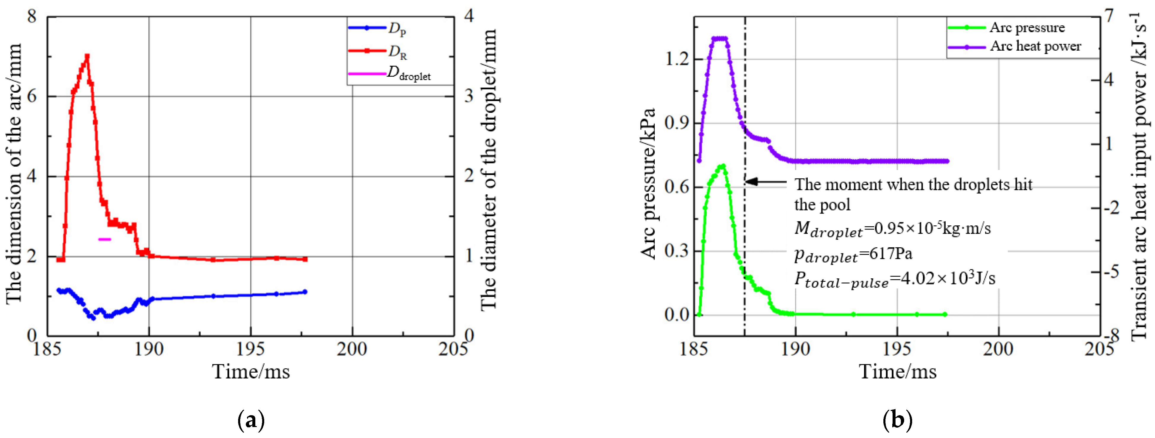
The droplet and arc sizes of the two waveforms in a single pulse cycle are shown in Figure 14a and Figure 15a. Combined with Equations (6)–(11), the heat and force acting on the weld pool in a single pulse cycle can be calculated, as shown in Figure 14b and Figure 15b. It can be found that the welding heat input power of the trapezoidal pulse and exponential pulse are similar, and the maximum value of arc size is close. However, the increase rate of arc size of the trapezoidal wave is significantly faster than that of the exponential wave, and the change of arc pressure shows a similar trend with the arc size. Although the peak arc pressure of the two waveforms is similar, the increased rate of arc size of the trapezoidal wave is significantly higher than that of the exponential wave due to the higher current rise rate of the trapezoidal pulse. As a result, its arc pressure rises faster, and its residence time above 600 Pa is longer than that of the exponential pulse. The droplet velocity of the trapezoidal pulse is significantly higher than that of the exponential pulse, and the droplet momentum and impact force of the trapezoidal pulse is higher than that of the exponential pulse.
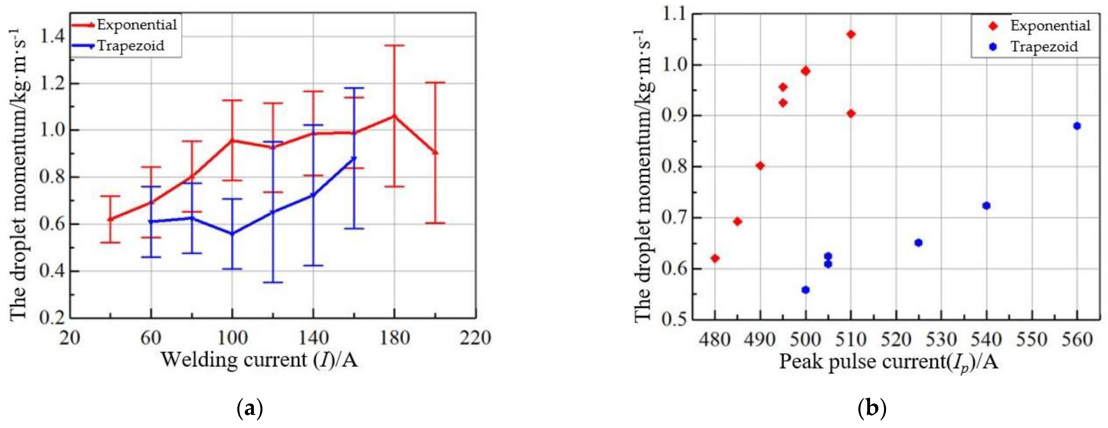
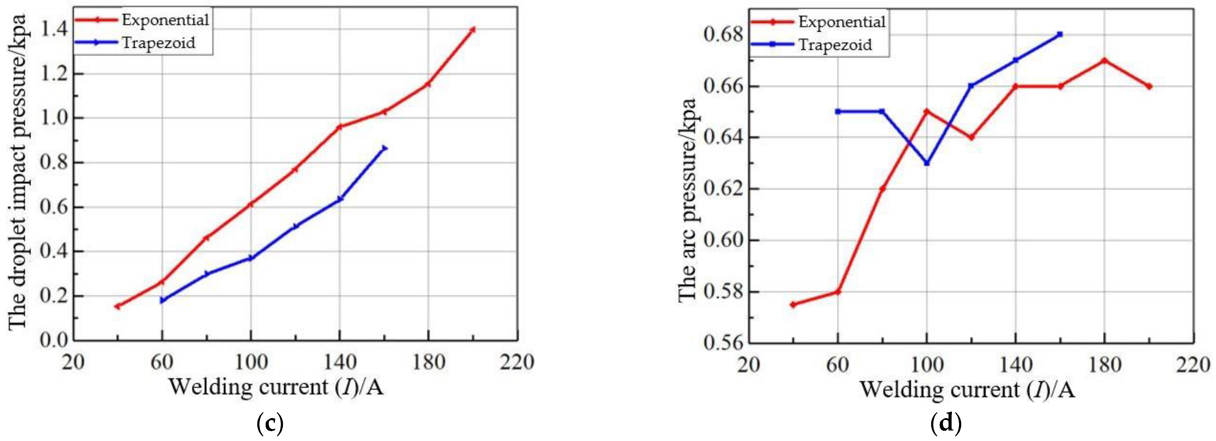
Figure 16 shows the variation trend of droplet momentum, equal impact force, and arc pressure of trapezoidal pulse and exponential pulse under different welding current conditions. According to Figure 16a–c, it can be found that the momentum and the droplet impact equivalent pressure of trapezoidal pulse are higher than those of exponential pulse under all current welding parameters. As shown in Figure 3a and Figure 16a, with the increase of welding current, the peak pulse current also increases, which leads to the synchronous increase of droplet speed and droplet quality, and the above factors all increase the momentum of the droplet. Figure 16d shows the peak pressure of the arc under different welding current conditions. Combined with the distribution of Ip in Figure 3a, it can be found that the peak pressure of the arc is positively correlated with Ip and has no significant correlation with the pulse waveform shape.

3.2. Effect of Current Waveform on the Welding Pool Dynamic Behavior and Microstructure

3.2.1. Effect of Current Waveform on the Dynamic Behavior of Welding Pool

In the welding process, Si, Mn, and other alloying elements in the base metal and welding wire have a high affinity with O elements in the protective gas, and SiO2 and MnO substances formed by oxidation of alloying elements float on the surface of the welding pool to form slag. The density of slag is lower than that of liquid metal, and researchers have shown that the movement behavior and accumulation position of molten slag reveals the flow behavior of the weld pool [25].
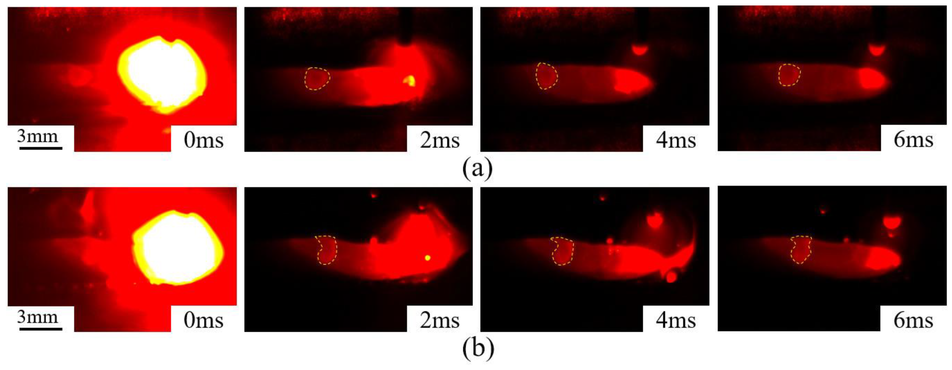
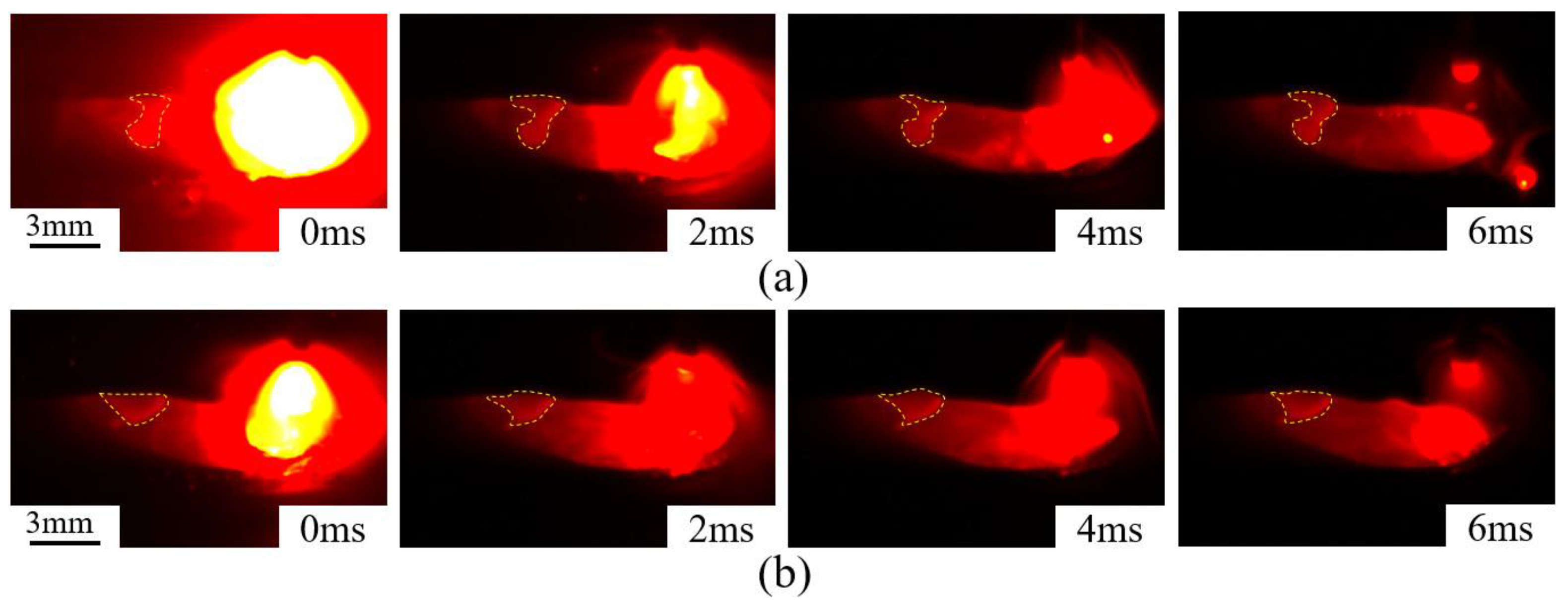
Figure 17 shows the high-speed photography of welding pool flow behavior and molten slag morphology with the Ip 485 A and 525 A, respectively. Figure 18 shows exponential pulse waveforms and trapezoid pulse waveforms with I = 100 A. According to the movement behavior of molten slag, a schematic diagram of the convection behavior of the molten pool can be deduced, as shown in Figure 19. After the front end of the welding pool is compressed, the metal flow is blocked by the bottom and forced to flow to the rear of the welding pool. After being rebounded by the rear edge, it moves to the front end of the welding pool. At the same time, the metal flow on the front surface of the welding pool will be pushed to the rear under the impact and surface tension, and the two metal flows will converge at the rear of the welding pool, resulting in the aggregation of metal oxides into slag blocks.
As shown in Figure 17, the welding pool with Ip = 485 A has a whole block of circular molten slag on its surface, and the welding pool surface with Ip = 525 A has a noticeable depression in the center of the molten slag.
As shown in Figure 18, The middle part of the molten slag on the surface of the trapezoidal pulse pool shrinking obviously, showing a typical “barbell” shape, while the molten slag of the exponential pulse gathered in a circle at the end of the welding pool.
The depression of the slag center indicates that it is subjected to strong convection extrusion in the welding pool. According to the content of Section 3.1, the droplet velocity is positively correlated with the convection intensity of the welding pool. Under the same parameters, the larger the droplet velocity, the higher the kinetic energy transferred during the momentum exchange of the impact welding pool, which leads to an increase in the convection intensity of the welding pool.

3.2.2. Effect of Current Waveform on the Solidification Process and Weld Microstructure

In the welding process, the front end of the welding pool is affected by the heat and force of the arc and the droplets, while the liquid metal at the rear of the welding pool solidifies continuously. Liquid metal is always in a complex state of motion. In order to better understand the influence of the current waveform on the solidification process of the molten pool, it is necessary to calculate the solidification rate of the welding pool (R), the cooling rate of the weld ( C R ) and the temperature gradient (GS and GL).
In the welding process, the liquid metal at the back edge of the welding pool solidifies rapidly, and the growth direction of the grains is related to the shape of the welding pool and the welding speed. In general, the grain of the weld is oriented in the welding direction and bent to the weld center, and the grain’s growth rate (R) is the linear speed of the trailing edge of the welding pool. Under the steady state and quasi-steady state welding conditions, the growth rate of columnar crystals at different positions on the edge of the welding pool changes with the distance from the center point at the tail of the welding pool. At the weld side boundary, the columnar crystal growth rate (R) tends to be 0. At the center point’s midpoint at the welding pool’s tail, the columnar crystal growth rate (R) tends to the welding speed V.
Another critical variable determining the microstructure structural characteristics of the weld is the cooling rate ( C R ). The weld energy and base metal thickness are the main factors determining the weld cooling rate. Considering the thickness and size of the base metal used in this paper, the cooling rate of the weld can be calculated by Equation (12) [26]:
C R = 2 π k ρ c l 2 ( T C T 0 ) 3 H n e t 2
where C R is the cooling rate (K·s−1), k is the thermal conductivity, T C is the liquid phase line temperature of the molten pool, T 0 is the ambient temperature, H n e t is the welding wire energy,   ρ is the density, c is the specific heat capacity, and l   is the plate thickness.
The solid phase temperature gradient (GS) and liquid phase temperature gradient (GL) on each side of the solid/liquid interface at the edge of the welding pool play a decisive role in the initial structure of the weld. GS can be calculated by Equation (13) as follows:
G s = C R R
GL plays a critical role in determining the morphology of the solid/liquid interface at the microscopic scale. It is proportional to the energy of the welding line and is strongly affected by the convection inside the welding pool. However, due to the limitation of technical conditions, the temperature gradient cannot be accurately measured, and at the same time, no relevant literature provides reference temperature gradient data. The temperature gradient in the welding pool is a function of material properties, welding process, position in the weld, and heat input, from which the general trend of liquid phase temperature gradient (GL) with the above factors can be obtained [5]. For the GMAW process, increasing of heat input will increase the welding pool size and reduce the temperature gradient.
The alloy solidification process is mainly affected by “component supercooling,” and the solid/liquid solute redistribution process in the welding pool solidification process is the main factor producing component supercooling. The degree of component supercooling at the solid/liquid interface is mainly affected by the degree of solute enrichment and the temperature gradient GL of the liquid phase of the welding pool. There is always vigorous stirring and convection in the welding pool of the GMAW process, which could significantly affect the liquid temperature gradient GL near the solid/liquid interface of the welding pool.
Measuring the GL and component subcooling in the welding process is complicated. Although there is no way to accurately measure the convection intensity, temperature gradient, and solute distribution in the welding pool, it has been shown that the convection enhancement could reduce the temperature gradient GL [27]. It can be inferred that the convection inside the GMAW welding pool could increase the degree of component undercooling, as shown in Figure 20.
The solute concentration distribution near the solid/liquid interface of the weld pool is shown by TL(x). In the case of convection and heat exchange of liquid metal in the welding pool, the liquid phase temperature gradient (GL) decreases, and the actual temperature T(x) near the liquid phase of the solid/liquid interface changes from blue line to red line, which aggravates the degree of component supercooling and then leads to the change of the solidification process.
Figure 21a and Figure 22a show the macroscopic cross-section photos of the weld with different pulse peak currents. The weld penetration depth is 0.7 mm with Ip = 485 A. When Ip = 525 A, the penetration depth increases to 1 mm. This indicates that higher Ip increases weld penetration depth. Figure 23a and Figure 24a show the macroscopic cross-section photos of a single pulse process weld with different pulse waveform shapes. The penetration depth of the trapezoidal pulse weld is 1.56 mm, and of the exponential pulse weld is 1.4 mm. Under the squeezing and pushing action of the pulse peak current, the overheated molten droplet metal directly enters the welding pool, melting the bottom base metal and the increase of the depth of the pool. The weld depth of the single pulse welding process is affected by the droplets’ speed, frequency, and temperature. Murray and Scotti et al. [10] analyzed the factors affecting the weld depth of GMAW from the perspective of heat and mass transfer, and the results showed that the heat of the droplets was the main factor affecting the weld depth. The study of Hosh et al. [28] showed that the temperature of the melting drop in the single pulse process was positively correlated with the pulse peak current. As mentioned in Section 3.1, increasing Ip significantly increases the melting velocity. Although it could lead to a decrease in pulse frequency, the equivalent impact force of the melting drop still rises slowly. Under the same welding current, the increase of Ip will simultaneously lead to the increase of the equivalent impact force of the melting drop and the increase of the temperature of the melting drop and then increase the weld penetration depth. With the same Ip, no research has been found on the influence of pulse waveform shape on the temperature of the droplet. However, as described in Section 3.1.2, the equivalent impact force of the trapezoidal pulse on the droplet is higher than that of the exponential pulse, which leads to the increase of the former penetration depth.
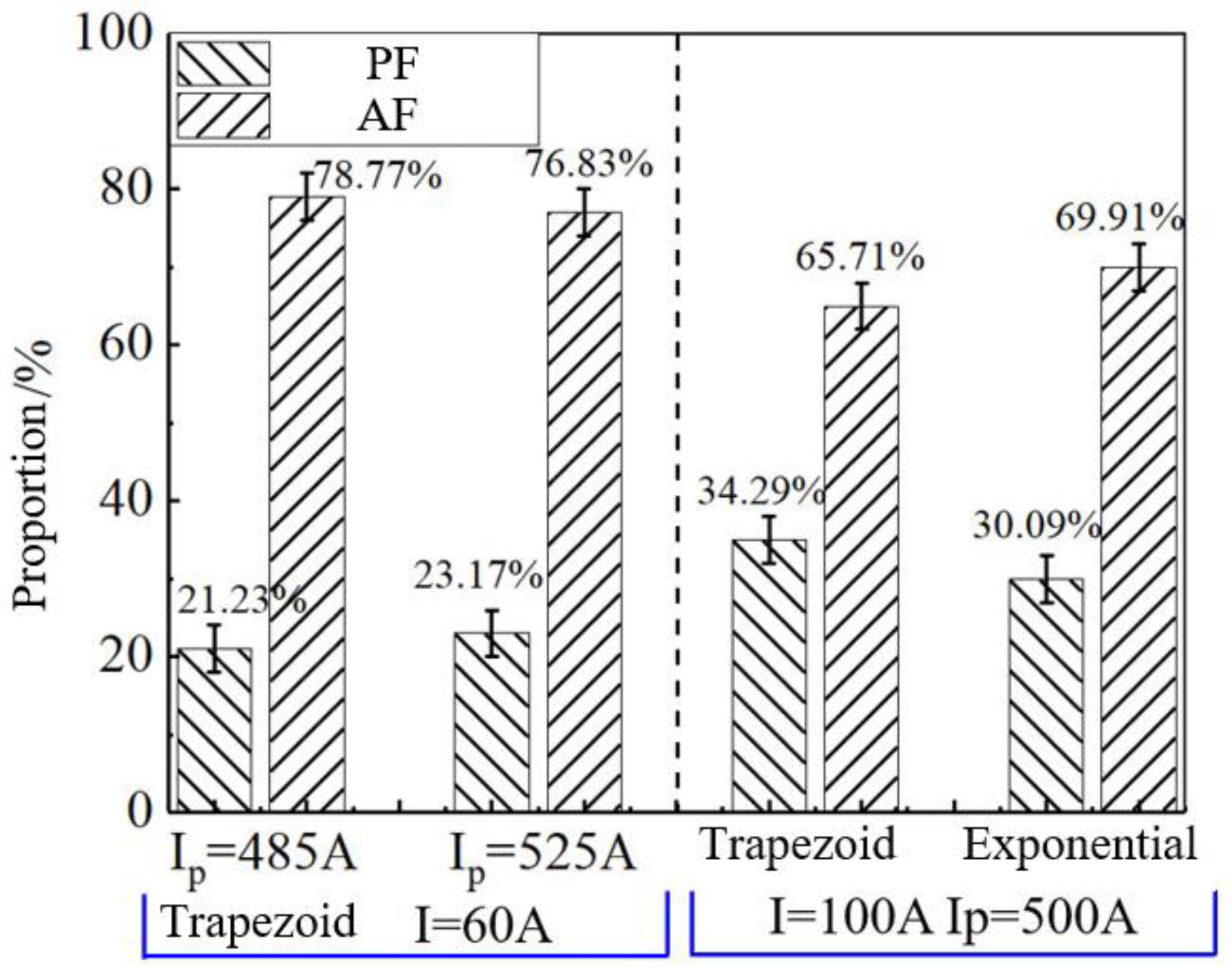
The peak current and shape of the pulse waveform also affected the weld structure. The weld structures with different Ips are shown in Figure 21b and Figure 22b, and the weld structures with different pulse waveform shapes are shown in Figure 23b and Figure 24b. The welded structure mainly comprises pro-eutectoid ferrite (PF) and acicular ferrite (AF). Figure 21b and Figure 22b show that the degree of intersection between adjacent PF dendrites in the welded tissue with Ip = 525 A is higher than that of Ip = 485 A. Figure 24b shows the exponential pulse weld tissue, in which the PF dendrites at the center show the same growth direction and are columnar dendrites. However, the PF phase in the trapezoidal pulse weld tissue shows a typical equiaxed dendrite morphology, as shown in Figure 23b. Figure 21c, Figure 22c, Figure 23c and Figure 24 shows the tissue’s metallographic photos of the AF phase. The average grain sizes of AF grain were calculated using the intercept method (as per ASTME112-10). It can be found that the pulse waveform parameters have no significant effect on the microstructure of the heat-affected zone with the same welding current, but the grain size of the AF phase is different. This paper measured the proportion of the AF and PF phases in the welded tissue under different pulse waveform parameters, as shown in Figure 25. The results showed that the proportion of the PF phase in the welded tissue with Ip = 525 A was higher than that with Ip = 485 A, and the proportion of the PF phase in the welded tissue with a trapeziform pulse was higher than that with an exponential pulse. At the same time, this section calculates the weld’s cooling rate, growth rate, and temperature gradient under different pulse waveform parameters, and the results are shown in Table 2. The cooling rate, growth rate, and temperature gradient of the weld under different pulse waveforms are all consistent with the same welding parameters, and the difference in the dynamic behavior of the weld pool caused by pulse waveforms is the main factor affecting the weld structure.
The convection intensity of the welding pool in the P-GMAW process is positively correlated with the droplet impact. The convection intensifies the subcooling degree during the solidification process and then changes the growth orientation of the primary austenite grain of the weld and reduces the cooling rate of the solidified weld area. Under different pulse waveform parameters, the droplet impact increase could lead to the intersection degree of adjacent PF dendrites in the weld microstructure and the transformation of the PF phase from columnar to equiaxial dendrites. At the same time, it also slows down the cooling rate of the solidified weld microstructure below the tail of the weld pool, resulting in a large amount of PF phase precipitation and an increase in AF phase grain size.

4. Conclusions

(1)
The arc pressure is positively correlated with the Ip. The extrusion of electromagnetic contraction force affects the droplet transition process and the impact of charged particles in the arc space. The droplet velocity and momentum are positively correlated with the peak pulse current.
(2)
The change of pulse waveform shape does not affect the peak pressure of the arc with the same pulse waveform parameters. Compared with the exponential pulse, the trapezoidal current pulse droplet has a shorter time to detach from the welding wire. The droplet is faster and has apparent deformation, leading to a more significant impact on the welding pool with the same parameter conditions.
(3)
The welding pool’s convection intensity and weld depth are positively correlated with the impact of the arc and droplet. The liquid convection reduces the temperature gradient of the welding pool, intensifies the component supercooling, and significantly changes the growth orientation of the primary austenite phase. The stronger the impact, the higher the proportion of PF phase in the weld microstructure, the larger the grain size of the PF phase and AF phase, and the intersection degree of adjacent PF phase dendrites increases.

Author Contributions

Conceptualization, J.H. and T.C.; methodology, J.H. and T.C.; software, J.H. and T.C.; validation, J.H. and T.C.; formal analysis, J.H. and T.C.; investigation, J.H. and T.C.; resources, J.H. and T.C.; data curation, T.C.; writing—original draft preparation, J.H.; writing—review and editing, J.H. and T.C.; visualization, J.H., T.C., D.H. and T.X.; supervision, J.H.; project administration, J.H.; funding acquisition, J.H. All authors have read and agreed to the published version of the manuscript.

Funding

This research was funded by the Ministry of Science and Technology Innovation Method Work Special Project: The Construction and Demonstration of Multi-level and Multi-mode College Innovation Method Talent Cultivation System, grant number 2017IM030100 and Education reform in Jiangsu Province: Exploration and practice of the “three-step” training model for top-notch talents through double innovation in higher vocational colleges, grant number 2017JSJG475.

Data Availability Statement

Data is available on request from the authors.

Conflicts of Interest

The authors declare no conflict of interest.

References

  1. Richards, R.W.; Jones, R.D.; Clements, P.D.; Clarke, H. Metallurgy of continuous hot dip aluminizing. Int. Mater. Rev. 2013, 39, 13–19. [Google Scholar]
  2. Kah, P.; Suoranta, R.; Martikainen, J. Advanced gas metal arc welding processes. Int. J. Adv. Manuf. Technol. 2013, 67, 655–674. [Google Scholar] [CrossRef]
  3. Fan, H.G.; Kovacevic, R. A unified model of transport phenomena in gas metal arc welding including electrode, arc plasma and molten pool. J. Phys. D Appl. Phys. 2004, 37, 2531. [Google Scholar] [CrossRef]
  4. Min, H.C.; Fa Rson, D.F. Understanding Bead Hump Formation in Gas Metal Arc Welding Using a Numerical Simulation. Metall. Mater. Trans. B 2007, 38, 305–319. [Google Scholar]
  5. David, S.A.; Vitek, J.M. Correlation between solidification parameters and weld microstructures. Metall. Rev. 2013, 34, 213–245. [Google Scholar] [CrossRef]
  6. Guo, J.; Zhou, Y.; Liu, C.; Wu, Q.; Chen, X.; Lu, J. Wire Arc Additive Manufacturing of AZ31 Magnesium Alloy: Grain Refinement by Adjusting Pulse Frequency. Materials 2016, 9, 823. [Google Scholar] [CrossRef] [Green Version]
  7. Jolanta, M.; Tomasz, P. The research of technological and environmental conditions during low-energetic gas-shielded metal arc welding of aluminium alloys. Weld. Int. 2013, 5, 338–344. [Google Scholar]
  8. Liu, A.; Tang, X.; Lu, F. Study on welding process and prosperities of AA5754 Al-alloy welded by double pulsed gas metal arc welding. Mater. Des. 2013, 50, 149–155. [Google Scholar] [CrossRef]
  9. Scotti, A.; Rodrigues, C. Determination of momentum as a mean of quantifying the mechanical energy delivered by droplets during MIG/MAG welding. Eur. Phys. J. Appl. Phys. 2009, 45, 11201. [Google Scholar] [CrossRef]
  10. Depth of penetration in gas metal arc welding. Sci. Technol. Weld. Join. 1999, 4, 111–118.
  11. Hussain, H.M.; Ghosh, P.K.; Gupta, P.C.; Potluri, N.B. Fatigue crack growth properties of pulse current multipass mig-weld of al-zn-mg alloy. Trans. Indian Inst. Met. 1997, 50, 275–285. [Google Scholar]
  12. Ghosh, P.K.; Yongyuth, P.; Gupta, P.C. Two-Dimensional Spatial Geometric Solution for Estimating the Macroconstituents Affecting the Mechanical Properties of Mulitpass C-Mn Steel SAW Deposits. Isij Int. 2007, 35, 63–70. [Google Scholar] [CrossRef] [Green Version]
  13. Cong, B.Q.; Yang, M.X.; Qi, B.J.; Li, W. Effects of pulse parameters on arc characteristics and weld penetration in hybrid pulse VP-GTAW of aluminum alloy. China Weld. 2010, 19, 68–73. [Google Scholar]
  14. Pal, K.; Pal, S.K. Effect of pulse parameters on weld quality. J. Mater. Eng. Perform. 2011, 20, 918–931. [Google Scholar] [CrossRef]
  15. Greene, W.J. An analysis of transfer in gas-shielded welding arcs. Trans. Am. Inst. Electr. Eng. Part II Appl. Ind. 1960, 79, 194–203. [Google Scholar]
  16. Arif, N.; Lee, J.H.; Yoo, C.D. Modelling of globular transfer considering momentum flux in GMAW. J. Phys. D Appl. Phys. 2008, 41, 195503. [Google Scholar] [CrossRef]
  17. Lancaster, J.F. The physics of fusion welding. Part 1: The electric arc in welding. IEE Proc. B. Electr. Power Appl. 2008, 134, 233–254. [Google Scholar] [CrossRef]
  18. Yudodibroto, M.; Hermans, M. Observations on Droplet and Arc Behavior during Pulsed GMAW. Weld. World 2009, 53, 171–180. [Google Scholar] [CrossRef]
  19. Wu, C.S.; Chen, M.A.; Lu, Y.F. Effect of current waveforms on metal transfer in pulsed gas metal arc welding. Meas. Sci. Technol. 2005, 16, 2459. [Google Scholar] [CrossRef]
  20. Hertel, M.; Spille-Kohoff, A.; Füssel, U.; Schnick, M. Numerical simulation of droplet detachment in pulsed gas–metal arc welding including the influence of metal vapour. J. Phys. D Appl. Phys. 2013, 46, 224003. [Google Scholar] [CrossRef]
  21. Hu, J.; Tsai, H.L. Heat and mass transfer in gas metal arc welding. Part I: The arc. Int. J. Heat Mass Transf. 2007, 50, 833–846. [Google Scholar] [CrossRef]
  22. Hu, J.; Tsai, H.L. Heat and mass transfer in gas metal arc welding. Part II: The metal. Int. J. Heat Mass Transf. 2007, 50, 808–820. [Google Scholar] [CrossRef]
  23. Haidar, J. The dynamic effects of metal vapour in gas metal arc welding. J. Phys. D Appl. Phys. 2010, 43, 165204. [Google Scholar] [CrossRef]
  24. Rouffet, M.E.; Wendt, M.; Goett, G.; Kozakov, R.; Schoepp, H.; Weltmann, K.D.; Uhrlandt, D. Spectroscopic investigation of the high-current phase of a pulsed GMAW process. J. Phys. D Appl. Phys. 2011, 43, 434003. [Google Scholar] [CrossRef] [Green Version]
  25. Ahsan, M.R.; Cheepu, M.; Ashiri, R.; Kim, T.H.; Jeong, C.; Park, Y.D. Mechanisms of weld pool flow and slag formation location in cold metal transfer (CMT) gas metal arc welding (GMAW). Weld. World 2017, 61, 1275–1285. [Google Scholar] [CrossRef]
  26. Sen, M.; Mukherjee, M.; Singh, S.K.; Pal, T.K. Effect of Double-Pulsed Gas Metal Arc Welding (DP-GMAW) Process Variables on Microstructural Constituents and Hardness of Low Carbon Steel Weld Deposits. J. Manuf. Process. 2017, 31, 424–439. [Google Scholar] [CrossRef]
  27. Yuan, T.; Luo, Z.; Kou, S. Grain refining of magnesium welds by arc oscillation. Acta Mater. 2016, 116, 166–176. [Google Scholar] [CrossRef]
  28. Ghosh, P.K.; Dorn, L.; Hübner, M.; Goyal, V.K. Arc characteristics and behaviour of metal transfer in pulsed current GMA welding of aluminium alloy. J. Mater. Process. Technol. 2007, 194, 163–175. [Google Scholar] [CrossRef]
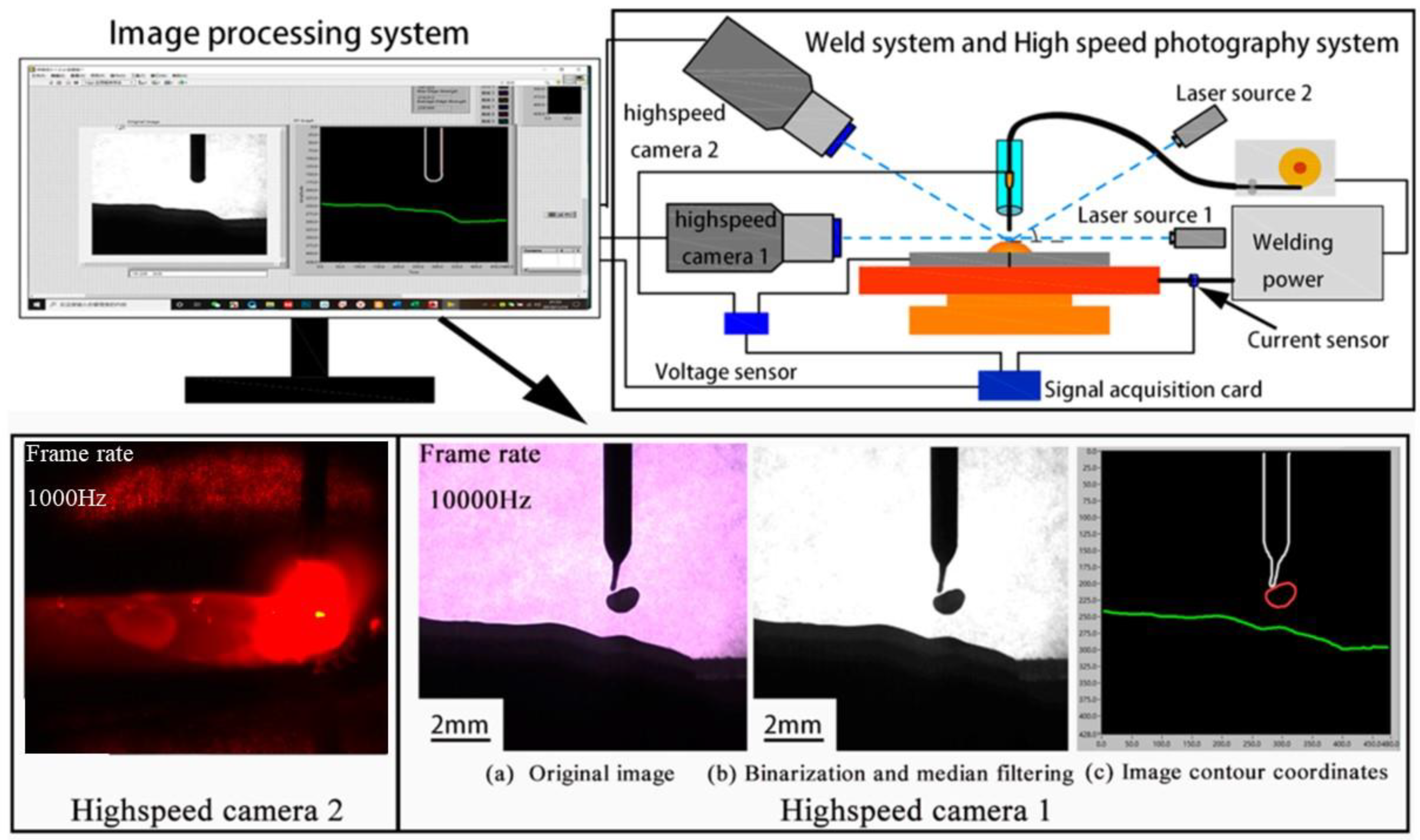
Figure 1. Experimental system and image processing system.
Metals 13 00199 g001
Figure 2. The droplet center of gravity position at a different time during P-GMAW welding.
Metals 13 00199 g002
Figure 3. The pulse waveform parameters with different currents supplied by a Fronius TPS5000 and Megmeet PM500A: (a) parameters of the waveform; (b) frequency of the pulse.
Metals 13 00199 g003
Figure 4. Schematic diagram of arc profile dimensions.
Metals 13 00199 g004
Figure 5. The current and voltage waveform in P-GMAW: (a) Ip = 485 A, I = 60 A; (b) Ip = 525 A, I = 60 A.
Metals 13 00199 g005
Figure 6. P-GMAW current and voltage signal and arc and droplet transition behavior photographs (Ip = 485 A): (a) current and voltage signal; (b) synchronous photographs.
Metals 13 00199 g006
Figure 7. P-GMAW current and voltage signal and arc and droplet transition behavior photographs (Ip = 525 A): (a) current and voltage signal; (b) synchronous photographs.
Metals 13 00199 g007
Figure 8. (a) The droplet and arc size at different times during a single pulse period (Ip = 485 A); (b) transient arc pressure and heat input power (Ip = 485 A).
Metals 13 00199 g008
Figure 9. (a) The droplet and arc size in different times during a single pulse period (Ip = 485 A); (b) transient arc pressure and heat input power (Ip = 525 A).
Metals 13 00199 g009
Figure 10. The phenomenon of multi-drop during one pulse (Ip = 525 A).
Metals 13 00199 g010
Figure 11. Effect of Ip on droplet momentum, arc, and droplet impact pressure. (a) The droplet momentum; (b) the pressure of the arc and droplet.
Metals 13 00199 g011
Figure 12. P-GMAW electronic signal and arc and droplet transition behavior photographs (trapezoid pulse waveforms, I = 100 A): (a) current and voltage signal; (b) synchronous photographs.
Metals 13 00199 g012
Figure 13. P-GMAW current and voltage signal and arc and droplet transition behavior photographs (exponential pulse waveform, I = 100 A): (a) current and voltage signal; (b) synchronous photographs.
Metals 13 00199 g013
Figure 14. (a) The droplet and arc size in different times during a single pulse period (exponential pulse waveform, I = 100 A); (b) transient arc pressure and heat input power (exponential pulse waveform, I = 100 A).
Metals 13 00199 g014
Figure 15. (a) The droplet and arc size at different times during a single pulse period (trapezoid pulse waveform, I = 100 A); (b) transient arc pressure and heat input power (trapezoid pulse waveform, I = 100 A).
Metals 13 00199 g015
Figure 16. (a) Droplet momentum with different welding current; (b) droplet momentum with different Ip; (c) the droplet impact equivalent pressure with different welding current; (d) the arc pressure with different welding current.
Metals 13 00199 g016aMetals 13 00199 g016b
Figure 17. Effect of Ip on the flow process of the welding pool and the morphology of molten slag in P-GMAW process: (a) Ip = 485 A; (b) Ip = 525 A.
Metals 13 00199 g017
Figure 18. Effect of pulse waveform shape on the flow process of the welding pool and the morphology of molten slag in P-GMAW process: (a) exponential pulse waveform; (b) trapezoid pulse waveform.
Metals 13 00199 g018
Figure 19. Schematic diagram of welding pool flow behavior.
Metals 13 00199 g019
Figure 20. Model of the influence of pool convection on the “component supercooling”.
Metals 13 00199 g020
Figure 21. Morphology and structure of weld (I = 60 A, Ip = 485 A): (a) macroscopic morphology of weld; (b) microstructure at the center of the weld; (c) high magnification image of the AF phase.
Metals 13 00199 g021
Figure 22. Morphology and structure of weld (I = 60 A, Ip = 525 A): (a) macroscopic morphology of weld; (b) microstructure at the center of the weld; (c) high magnification image of the AF phase.
Metals 13 00199 g022
Figure 23. Morphology and structure of weld (I = 100 A, exponential pulse waveform): (a) macroscopic morphology of weld; (b) microstructure at the center of the weld; (c) high magnification image of the AF phase.
Metals 13 00199 g023
Figure 24. Morphology and structure of weld (I = 100 A, trapezoid pulse waveform): (a) macroscopic morphology of weld; (b) microstructure at the center of the weld; (c) high magnification image of the AF phase.
Metals 13 00199 g024
Figure 25. The volume proportion of PF phase and AF phase in weld microstructure.
Metals 13 00199 g025
Table 1. The welding parameters used in this article.
WaveformI/AIp/AIb/A
1Trapezoidal type60485–52520
2Exponential type10050020
3Trapezoidal type40–200Set automatically
4Exponential type60–180Set automatically
Table 2. The welding parameters used in this article.
WaveformI/AV/cm·min−1Ip/A H n e t / J mm−1 C R / K s−1R/mm s−1Gs/K·mm−1
Trapezoidal type6025485312.3150.74.137.2
6025525310.9152.14.136.5
10038.5500345.6128.86.420.1
Exponential type10038.5500338.1129.86.420.3
Disclaimer/Publisher’s Note: The statements, opinions and data contained in all publications are solely those of the individual author(s) and contributor(s) and not of MDPI and/or the editor(s). MDPI and/or the editor(s) disclaim responsibility for any injury to people or property resulting from any ideas, methods, instructions or products referred to in the content.