Article

Resistance of Heterogeneous Metal Compositions to Fracture under Dynamic and Cyclic Loads

by
Leonid K. Leshchinskiy
1,
Vitaliy P. Ivanov
1,
Elena V. Lavrova
1 and
Dmitry P. Il’yaschenko
2,3,*
1
Institute of Modern Technologies, Pryazovskyi State Technical University, Universitetskaya 7, 287555 Mariupol, Russia
2
Yurga Technological Institute, National Research Tomsk Polytechnic University, 30 Lenina Prospekt, 634050 Tomsk, Russia
3
Institute of Strength Physics and Materials Science of Siberian Branch Russian Academy of Sciences, Academic Ave., 2/4, 634055 Tomsk, Russia
*
Author to whom correspondence should be addressed.
Metals 2023, 13(11), 1899; https://doi.org/10.3390/met13111899
Submission received: 20 September 2023 / Revised: 5 November 2023 / Accepted: 11 November 2023 / Published: 17 November 2023

Abstract

:
This paper presents the results of experimental data analysis, which indicate an increased resistance of heterogeneous multilayer clad composites to dynamic loading destruction compared with homogeneous materials. The reason for this is the crack retardation caused by lamination at the boundary of the layers. The destruction of heterogeneous compact composite samples by cyclic off-center stretching also occurs with crack retardation, with the fractogram clearly demonstrating the transverse tightening of the sample section. We argue that crack nucleation plays a decisive role in the process of dynamic destruction of heterogeneous composites obtained by both multilayer cladding and explosion welding. This study presents generalized calculated data confirming the influence of the sign and magnitude of residual stresses (the appearance of a stress discontinuity) on the conditions of fatigue surface crack nucleation and propagation. Unlike homogeneous materials obtained by casting, forging (rolling), or cladding, which are characterized by a linear dependence of the crack propagation velocity on the dynamic stress intensity coefficient, for multilayer composites consisting of strong and viscous layers, a sharp crack deceleration is observed. This is due to the transition of the crack boundary between the strong and viscous layers. This paper presents studies of the corresponding properties of adjacent layers on the integral characteristics of the deposited composite.

1. Introduction

The formation of multilayer composites with layers of heterogeneous composition and structure (or only structure) is a method for increasing the fracture resistance of metal materials under the influence of dynamic and cyclic loads. An increase in fracture resistance is related to the deceleration (retardation) of the crack perpendicular to the boundary of the layers in composites with layers connected by fusion or pressure welding. Different mechanisms may be employed in retardation, depending on the strength of the adhesive bond between adjacent layers in comparison with the mechanical properties of the layers. The prospects of utilizing heterogeneous composites obtained through cladding [1], surface hardening, or other methods with a certain number of layers of the required height depend on several factors, such as the optimal structure achieved through lean alloyed materials, reliability, technological stability, and energy efficiency during the composite formation process. Several studies on layered metal composites highlight the benefits of welding and friction treatments with mixing over conventional liquid-phase processing techniques. The study [2] investigated the feasibility of using upward friction stir processing (UFSP) technology to create surface composites of dissimilar aluminum-based alloys that are reinforced with functional microparticles. Research findings reported in [3] indicate that electro-spark deposition (ESD) can be used to produce composite materials.
Although the mechanical properties of these materials in their initial state have been studied in sufficient detail, predicting the developing processes of destruction under various load conditions remains a difficult task because of the complexity of the structural state and numerous damage mechanisms [4]. With uniaxial loading of a layered material, the stress state of each layer may significantly differ from that of the neighboring layers [5] because of their unique mechanical and thermophysical properties, since the average physical and mechanical properties cannot be indicators of resistance to a specific destructive force factor, even for the surface layer of a composite material [6]. If the load is applied in two or three axes, the developed models for predicting the resistance [7,8] of layered metal composites cannot be effectively used for many cases of practical operation of multilayer structures.
A criterion that considers the total amount of damage over time has been suggested [9] as a way to measure the fatigue strength of composite materials. This indicator is of a statistical nature because there may be crack interactions between layers when several layers develop cracks simultaneously due to long-term loading. The model proposed in [10] can be used to effectively predict the development of cracks in multilayer compositions and assess the long-term durability of load-bearing structures. In [11], an energy model was developed to predict the evolution of the subcritical density of matrix cracks in multidirectional symmetric laminates under multiaxial stress states.
The retardation of the main crack and delamination described by the Cook–Gordon mechanism occurs when the adhesive strength of the interface is lower than that of the layers. Gordon numerically estimated the conditions required for implementing a mechanism to describe a crack of any shape by correlating the maximum stresses along the direction of the crack with the maximum stresses directed perpendicular to its surface [12]. To achieve these conditions, it is necessary to obtain a given composition (doping level) for each layer as well as a high contrast in the properties at their boundaries. This can increase crack resistance by retarding fracture at the boundary through the mechanism of the lamination formation. Additionally, ensuring reliable penetration of layers is crucial in preventing the formation of defects such as incomplete fusion [13]. This problem can be solved using strip cladding under flux technology. This approach involves selecting appropriate strip sizes, flux composition, and mode parameters. Unlike single-layer corrosion-resistant cladding [14], multilayer wear-resistant composites can be formed from layers of high strength and high plasticity (in particular, 10Cr13–30Cr13–10Cr13, 15Cr4MnMoV–25Cr5VMoSi–15Cr4MnMoV). A reduction in the crack resistance of these composites results in a decrease in the impact strength of the metal in the overlap regions of neighboring rollers when exposed to reheating. To a large extent, this is caused by the low strength and brittleness of the heat-affected zone at the boundary between the first deposited layer (sublayer) and the base metal. This is especially true if the base metal is steel with limited or low weldability [15]. The potential destruction of welded or clad composites is linked to the structural heterogeneity (interlayers) that forms near the fusion boundary [16]. For the fusion zone of 15Cr1Mo1V and 10CrMoVNb steels, the possibility of destruction depends primarily on the influence of the most dangerous soft layers (the cast seam structure and softening zones in the HAZ). The dynamic fracture of composites with weaker interlayer bonding than that formed by fusion or pressure welding shows even more pronounced crack retardation due to lamination formation. This was demonstrated in a study of impact destruction testing of a composite obtained by hot-rolling a package of 09Mn2Si and 03Cr11Ni10Mo2Ti steels [17].
Contrary to the described mechanism, the main crack retardation in composites lacking a clearly defined separation (connection) line between layers results from crack deviation, or branching. This occurs under the influence of a discontinuity in the residual stress diagram, which is formed when the structure of the deposited metal changes with a variation in the direction of crystallization caused by changing the cladding direction (substituting the cladding direction along the helical line with the direction along the generatrix) [18]. The analysis of the causes of destruction of steel samples hardened by surface hardening considers the same mechanism of crack retardation. In this case, the hardened layer has the same composition but a different structural state (in particular, a different degree of dispersion) from the adjacent layer. Retardation due to the crack trajectory curvature can occur during the destruction of a welded structure made of thermally reinforced sheet materials [19]. Such a material can be reasonably considered to be macro-heterogeneous, and its gradient structure consists of sections with different mechanical properties. The physical model used to study the destruction of a thermally reinforced sheet revealed that secondary cracks that deviate from the main crack direction are initiated when the latter crosses the hardened section. The branching effect is more prominent when the strength ratio between the thermally hardened and non-hardened sections of rolled sheets composed of low-alloy tube steels is within the range of 1.4 to 1.5. A significant decrease in the rate of fatigue crack propagation was observed during the destruction of welded joints subjected to ultrasonic shock surface treatment (ultrasonic forging). Thus, due to changes in the conditions of the nucleation and propagation of the crack, the fatigue life of the welded joint increases almost two-fold [20].
It should be noted that to date, the influence of the characteristics and properties of homogeneous (monolithic) layers and their combinations on the macroscopic parameters of the entire composite, its properties and performance as a whole has not been established. There are no studies identifying the contribution of the transition zone, which, for example, when using surfacing to produce layered materials, has fairly extended dimensions [21]. In each specific case, it is not clear what materials and what ratio of characteristics of adjacent layers are necessary to obtain the desired properties of the composite layer. This article is devoted to certain aspects of this problem.

2. Materials and Methods

2.1. Characteristics of the Studied Materials

The development of crack-resistant layered composites with macro-heterogeneous cladding requires study of the individual layers’ resistance to destruction from dynamic and cyclic loading effects. Tests for the dynamic crack resistance of samples of clad metal, as well as centrifugal cast and forged metal, were conducted on prismatic samples measuring 10 × 10 × 55 mm at a temperature of 20 °C using pendulum copra equipped with a strain gauge. (The compositions and properties of the materials under study are presented in Table 1 and Table 2).
This allows the fracture waveforms to be recorded in force-time coordinates and mathematically processed to determine the crack resistance properties (impact strength KCV and dynamic stress intensity coefficient Kcd). In addition, the recording on the oscillogram allows the integral value of the impact strength to be divided, highlighting the part associated with elastic and plastic deformation of the sample until the crack appears (energy costs for crack nucleation KCn), as well as the second part associated with energy costs for crack propagation KCp.
For the same materials, the fatigue crack propagation rate was estimated based on the results of cyclic tests conducted according to a scheme involving three-point bending of the prismatic samples (15 × 15 × 150 mm) with a sharp 1.5 mm deep incision and a bottom radius of less than 0.25 mm; the loading frequency was 50 Hz with the asymmetry of the cycle R = −1. The data obtained allow the construction a kinetic diagram of fatigue failure in the coordinates “fatigue crack growth rate dl/dN and the magnitude of the stress intensity coefficient ΔK”.

2.2. Study of Macrostructural Characteristics of Monolithic Materials and Composites

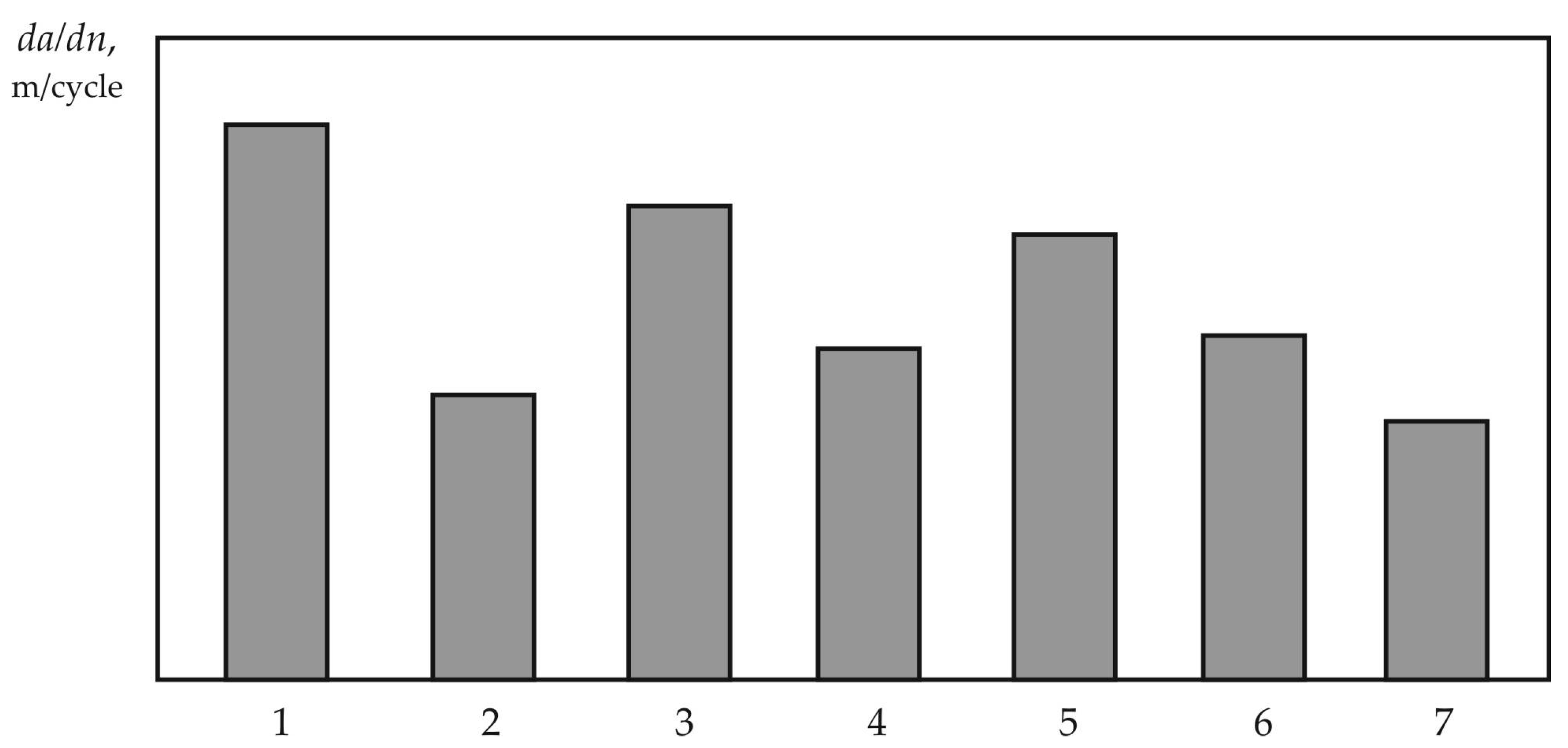
The impact strength of a monolithic metal, which characterizes its resistance to dynamic destruction, depends on its chemical composition and structural state. As can be seen from Figure 1, for the compositions of the clad metal (1, 3, 4, 5), the impact strength monotonically increases from 35Cr3W9 to 12Cr12Mn12SiV. The impact strength almost triples during the transition from the 35W9Cr3VSi composition with the structure of twinned martensite, carbide eutectic (large carbides located along the grain boundaries), and isolated low-strength ferrite sections to the 25Cr5VMoC composition with the structure of lath martensite and partial crystals of twinned martensite. The stark difference may be attributed to the negative impact on crack resistance of the structure containing massive tungsten carbides along the grain boundaries. The resistance of the clad metal 25Cr5VMoC to fatigue crack propagation is higher than that of the tungsten-doped 35Cr3W9 composition and is similar to the crack propagation resistance during dynamic fracture (Figure 2). The destruction of 35Cr3W9 steel is of a characteristic brittle mixed nature, i.e., intergranular spalling and intragranular fracture. In contrast, separate areas of viscous fracture were observed in the destruction of 25Cr5VMoSi steel. The composition 10Cr13, which exhibits a higher integral impact strength value, differs from the discussed clad metal composites. In addition, the fine-grained martensitic-ferritic structure provides high resistance to crack formation under both dynamic and cyclic loading. The chromium content in 10CR13 exceeds the second critical concentration; the steel becomes stainless, and the limit of corrosion-fatigue endurance of this steel in fresh water is much higher than that of the austenitic steel 10Cr18Ni9. The clad 12Cr12Mn12SiV metal with the structure of metastable austenite is also stainless, and the increased energy intensity of this structure provides a slightly higher impact strength of the clad metal than that of the 10Cr13 composition. The resistance of the 12Cr12Mn12SiV composition to destruction through cyclic loading is notably lower than that of the 10Cr13 composition. However, it differs only slightly from the resistance of 25Cr5VMoSi, considering the differences in the structures and mechanical properties. The metastable austenite structure of the clad 12Cr12Mn12SiV metal has a much lower resistance to fatigue crack nucleation than 10Cr13. In addition, the higher fatigue crack propagation rate in 12Cr12Mn12SiV is related to the insufficient tensile strength and ductility of the metal.
The 17Cr12Mo2V centrifugal-cast steel, used as a surface layer on rollers of continuous casting machines (CCM), exhibits no casting defects and possesses a fine-grained, high-density structure composed of lath martensite and ferrite hardened with fine carbides. High strength and, in particular, ductility in steel (relative transverse contraction of 54%) are correlated with molybdenum content (2.1%), which alloys a solid solution and creates dispersed carbides. The low impact toughness value of this metal (see Figure 1) may have resulted from the heat treatment process employed for the CCM roller, from which the test samples were cut from the surface layer. In contrast to the centrifugal cast, the material of the solid-forged rollers is 25Cr1Mo1V steel with a finely dispersed structure of tempered martensite, which is characterized by high impact strength and toughness (Figure 1). Its values exceed those of the clad metal compositions considered, and the plasticity of steel 25Cr1Mo1V is not less than that of steel 17Cr12Mo2V. The dynamic destruction micro-mechanism of 25Cr1Mo1V steel is quasi-spalling; the destruction mechanism of centrifugal cast steel is less energy intensive.
Significantly, a comparison of the fatigue crack propagation rate in the steels under consideration revealed that the plastically deformed metal 25Cr1Mo1V exhibits a higher crack propagation rate (Figure 2). Here, the micro-mechanism of destruction involves both inter-granular spalling and localized areas of viscous destruction. The fracture exhibits a comb-shaped relief. The heterogeneity of the microstructure contributes to the increased resistance to destruction by cyclic loading of 17Cr12Mo2V steel. The crack passes through martensite, which has a microhardness of 5000–6000 MPa, before losing speed and blunting at the interface with the more plastic phase, ferrite. The microhardness of ferrite is 2500–2700 MPa. Leaving the ferrite and entering a stronger martensitic phase, the crack decelerates because of the rigid stress state at the apex. The uneven movement of the crack is accompanied by its retardation and can lead to its stopping. The micro-mechanism of 17Cr12Mo2V fatigue failure is energy intensive, and the microrelief in the fatigue fracture zone is grooved.
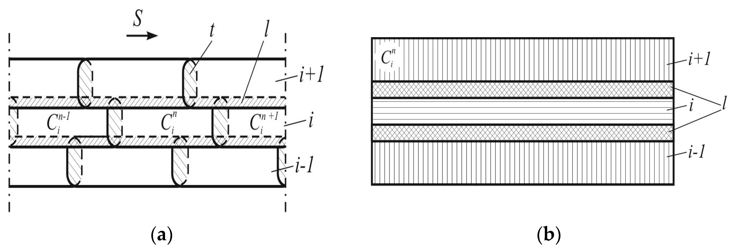
The influence of structural heterogeneity on destruction retardation is more evident in heterogeneous layered composites consisting of lean-alloyed clad layers. Thus, we assessed the fracture resistance of the 18Cr6MnMoVSi–15MnSi–18Cr6MnMoVSi composite subjected to dynamic and cyclic loading. An alternating layer composite consisting of 18Cr6MnMoVSi and 15MnSi was obtained by multilayer cladding with an Sv-08kp strip electrode under an alloying ceramic flux and an Sv-15MnSi strip electrode under an AN-60 flux, respectively. The technology of strip electrode cladding under flux allows welding of adjacent strong and plastic layers with strictly limited mutual penetration and a contrasting boundary between them (Figure 3), as evidenced by the distribution of hardness across the layers (Table 3).
The study of the dynamic crack resistance of such a composite was performed according to the above method. The study was conducted using standard samples with a sharp incision made perpendicular to the plane of the layer interface. Because of the viscous inner layer, the destruction of the layered composite during impact bending occurs in several stages and is characterized by crack retardation at the boundary of the layers as a result of micro-layer formation. The clad layer of 18Cr6MnMoVSi, which has a structure of high-tempered martensite with elongated lath crystals and carbides in the body and along the boundaries of martensitic crystals, is destroyed by a mixed mechanism, including transcrystalline spalling with areas of viscous dimple rupture, and the deposited layer of 15MnSi is destroyed by a microviscid dimple rupture mechanism. For the three-layer composite, the impact strength reached 1.50 MJ/m2, and for the deposited homogeneous 18Cr6MnMoVSi metal it was 0.42 MJ/m2 (stress intensity coefficients: Kcd = 65.0 MPa∙m1/2 and 46.0 MPa∙m1/2, respectively).
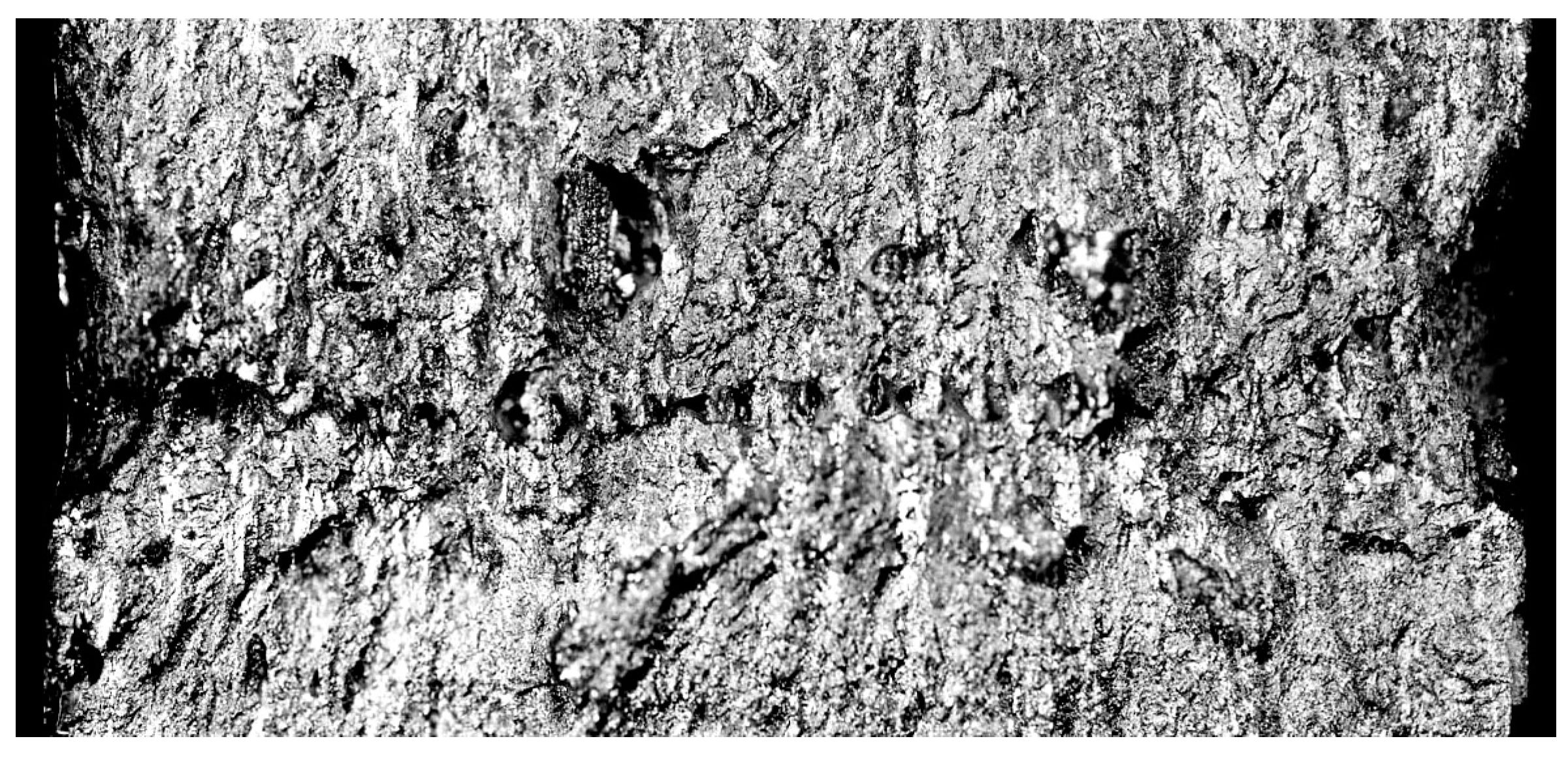
The resistance to cyclic destruction of the layered 18Cr6MnMoVSi–15MnSi–18Cr6MnMoVSi composite was evaluated during the testing of compact samples by off-center stretching. The micro-voids (pores) formed in the process of viscous destruction merge to form a dimple rupture (Figure 4). During the cyclic load, the viscous fracture follows plastic deformation, and the sample cross-section is observed to experience tightening.
The critical zone of plastic deformation expands at the slip crack’s mouth when it develops in the main direction [22]. The destruction caused by cyclic loading is distinguished from dynamic destruction by the suppression of microplastic deformation, which occurs because of the high rate of deformation.

3. Results and Discussion

The resistance to dynamic destruction of the deposited metal is largely determined by the work of crack generation. Oscillography tests of the fracture process can determine the integral value of the impact strength, and isolate the crack nucleation and the work of its propagation in a layered composite (see Table 4). The analysis included studying the samples obtained by cladding a layer of 30CrMnSi steel onto 90CrV eutectoid steel, which had a pearlitic structure. Samples of 12Cr18Ni10Ti and 15 kp steels with intermediate layers were tested to determine the impact of a viscous intermediate layer. For samples with an intermediate layer, the integral value of the impact strength increases by 1.4–1.9 times, which is caused by an increase in the specific work of crack nucleation. The austenitic metal’s properties, including its fine grain and smaller spread of dimensions, determine the increased impact strength values obtained using a 12Cr18Ni10Ti steel sublayer. Additionally, compared with the ferrite-pearlite structure of 15 kp steel, the flow stress of the austenitic structure is 20–25% higher. The increase in crack resistance due to lamination is associated with the crack stopping at the boundary of a strong and viscous layer, which is a crack localization barrier. When the crack approaches the boundary of these layers, the stress–strain state at the crack tip changes because of stress relaxation upon encountering a soft component. When the crack from the destroyed composite deposits enters the lamination structure, it stops because of a sharp increase in the radius of the tip. This stoppage leads to the creation of a new crack. For all the variants of layer compositions, the work of crack nucleation is approximately the same. However, unlike a three-layer metal composite with a sublayer of 15 kp steel, in the case of a sublayer of steel 12Cr18Ni10Ti, the work of crack nucleation KCn is approximately equal to the work of its propagation KCp; however, the proportion of KCn increases significantly with a change in the ratio of the layers’ thicknesses (an increase in the thickness of the 30CrMnSi layer).
The dynamic destruction mechanism of layers obtained by cladding, which is similar to the one described above, can be observed in multilayer composites acquired through explosion welding [23]. In this process, the adhesive strength of the layers’ connections differs from that of fusion welding. Impact tests on a five-layer composite (three layers of 09Mn2Si steel and two layers of 03Cr11Ni10Mo2Ti steel) produced by explosion welding demonstrated that the crack deviates along the interlayer boundary, resulting in delamination (splitting) that decelerates the crack. The work of crack nucleation makes an important contribution to improving the resistance of such composites to destruction by shock loading. It is proposed that the fracture resistance, along with the impact strength value, can be evaluated by the dynamic crack resistance parameter Jid, which is calculated based on the magnitude of the crack nucleation work An [24]:
Jid = 2An/W(Ha),
where W is the width of the sample; H is the height of the sample; and a is the depth of the incision.
The test results analysis revealed that the composite’s impact strength (0.92 MJ/m2) is greater than the values measured for each individual layer, including steel 09Mn2Si, which was used here as a viscous layer with high resistance to cracking. The values of the dynamic crack resistance parameter Jid for the composite are also higher than those for individual layers.
One of the main reasons for crack retardation at the boundary of the brittle and viscous layers is the formation of a stress discontinuity at this location. The magnitude and sign of the residual stresses formed during the cladding process affect the behavior of the fatigue crack spreading from the surface to the depth of the product. However, the calculated outcomes and experimental observations prove that under a thermally pressured state resembling a hot metal deformation tool’s operating circumstances (such as working rolls of hot rolling mills, continuous casting rollers, and hot stamping dies), this effect can take two basic forms. The first involves increased resistance to crack nucleation, and the second involves retardation of surface cracks at the boundary between the metal layers and the base metal. The formation of residual compression stresses in the surface layer leads to an increase in the resistance to crack nucleation, which is confirmed when a layer of 10Cr13 steel with a martensitic-ferritic structure is clad on the base of the CCM roller (steel 25Cr1Mo1V). The compression stresses on the roller surface may not exceed 200 MPa, but at the same time, the resistance to crack formation increases significantly. Thus, the number of loading cycles required when operating continuous casting rollers with a 300 mm diameter and a 10Cr13 layer deposited with a thickness of 7.5 mm before the surface crack forms is significantly higher than the average value of ~5000 and significantly higher than that for rollers deposited with austenitic steel [25]. However, if tensile stresses of +200 MPa are formed at the boundary of the clad layer with the base metal and the discontinuity is insufficient (from 200 MPa up to +200 MPa), the crack crosses the border (Table 5). And certainly, the surface crack does not stop when tensile stresses are formed at this location (from +300 MPa up to +600 MPa). The probability of surface crack retardation substantially increases if the level of tensile axial thermal stresses from the surface deep into the roller decreases abruptly at the boundary of layers with significantly different thermophysical properties (from +850 MPa up to +300 MPa). The crack is even more likely to stop under compression stresses (200 MPa) at the boundary between the clad layer and the base metal.
This is confirmed by the fatigue crack retardation at the fusion boundary between the clad 12Cr12Mn12SiV layer and the metastable austenite structure of the roller’s 25Cr1Mo1V steel. When a layer of 0Cr17Ni4 with a ferritic structure is clad onto the roller material (12Cr1Mo1V steel), the compression stresses generated on the roller surface and at the boundary with the base metal (Table 5) prevent surface cracking.
The linear nature of the dependence of dl/dN on the change in ΔK on the kinetic diagram of fatigue failure (KDFF), indicating a constant rate of crack propagation, is characteristic of monolithic materials, for example, sheet steel 09Mn2Si. The same characteristics of the crack propagation rate were established for the cast structure of homogeneous clad-layered and centrifugal-cast metal, as well as for that obtained by forging.
Importantly, the fatigue failure process of a heterogeneous multilayer composition obtained through explosion welding is characterized in the kinetic diagram by specific dips [23,26]. These dips are connected with the change in the nature of fatigue crack propagation when moving toward the boundary of the layers and crossing this boundary. The sharp decrease in the crack velocity that occurs in this case leads to abnormal dips on the KDFF in the boundary zone of a viscous layer (steel 09Mn2Si) and a stronger one (martensitic-aging steel 03Cr11Ni10Mo2Ti). The dip is associated with the layered structure and the correlation of the mechanical properties of the layers. According to the study [23], the retardation effect occurs prior to the crack tip reaching the interface of the layers. At this point, the plastic deformation zone formed at the crack tip changes its shape, which ultimately slows down crack propagation before it reaches the layer boundary. Two types of five-layer composites were used in the tests (each of three layers of 09Mn2Si steel and two layers of 03Cr11Ni10Mo2Ti steel): a conventional fine-grained structure of martensitic-aging steel and an ultra-fine-grained structure of this steel obtained by thermoplastic processing.
According to results obtained in previous studies [23,26], the most interesting is the interval of changes in ΔK = 24–32 MPa·m1/2, within which dips in KDFF are observed. The dips’ shape and depth and the fatigue crack rates change significantly vary between composites with fine-grained and ultra-fine-grained structures containing layers of martensitic-aging steel. This may be attributed to variations in the strength and ductility properties resulting from thermomechanical processing.

4. Summary

  • The improved resistance to dynamic load destruction of the studied heterogeneous multilayer composites obtained by fusion and pressure welding is related to crack retardation due to the lamination mechanism at the boundary between the strong and viscous layers. The integral value of the impact strength of these composites primarily depends on crack nucleation work.
  • According to the analyzed data, residual stresses may increase the resistance to fatigue crack nucleation or crack retardation at the boundary of layers in heterogeneous composites.
  • The dependency between dl/dN and ΔK appears linear when observing the kinetic diagram of fatigue failure mechanisms of monolithic materials with a cast or plastically deformed structure, as well as homogeneous layered deposited composites. However, in the case of multilayer composites consisting of viscous and strong layers that are connected by welding explosion, a sharp slowdown of fatigue crack occurs in the form of a dip due to the crack’s crossing the boundary between a strong and viscous layer.

Author Contributions

Conceptualization, L.K.L. and E.V.L.; Methodology, L.K.L., V.P.I., E.V.L. and D.P.I.; Formal analysis, V.P.I.; Investigation, L.K.L., V.P.I., E.V.L. and D.P.I.; Data curation, E.V.L.; Writing—review and editing, V.P.I. and D.P.I.; Visualization, V.P.I. and D.P.I.; Project administration, L.K.L., V.P.I. and E.V.L. All authors have read and agreed to the published version of the manuscript.

Funding

This research was funded by the Government research assignment for ISPMS SB RAS grant number FWRW-2021-0003.

Data Availability Statement

Scientific data presented in the article “Leshchinskiy, L.K.; Ivanov, V.P.; Lavrova, E.V.; Il’yaschenko, D.P. Resistance of Heterogeneous Metal Compositions to Fracture under Dynamic and Cyclic Loads. Metals 2023, 13” original, published for the first time and received by the authors of the article.

Acknowledgments

The investigation of the grain structures was performed according to the Government research assignment for ISPMS SB RAS, project FWRW-2021-0003.

Conflicts of Interest

The authors declare that they have no conflict of interest to report regarding the present study.

References

  1. Ivanov, V.P.; Leshchinskiy, L.K.; Stepnov, K.K. Control of alloying process of weld metal of variable chemical composition. Weld. Int. 2021, 35, 441–446. [Google Scholar] [CrossRef]
  2. Moreira, F.; Ferreira, P.M.; Silva, R.J.C.; Santos, T.G.; Vidal, C. Aluminum-Based Dissimilar Alloys Surface Composites Reinforced with Functional Microparticles Produced by Upward Friction Stir Processing. Coatings 2023, 13, 962. [Google Scholar] [CrossRef]
  3. Kulasa, J.; Juszczyk, B.; Kováčik, J.; Emmer, Š.; Malara, S.; Malec, W.; Lis, M. Wear resistant and electrically conductive composite coatings on non-ferrous metals. In Proceedings of the European Congress and Exhibition on Advanced Materials and Processes, Thessaloniki, Greece, 17–22 September 2017. [Google Scholar]
  4. Berton, T.; Haldar, S.; Montesano, J.; Singh, C.V. Time-dependent damage analysis for viscoelastic-viscoplastic structural laminates under biaxial loading. Composite Struct. 2018, 203, 60–70. [Google Scholar] [CrossRef]
  5. Singh, C.V.; Talreja, R. Evolution of ply cracks in multidirectional composite laminates. Int. J. Solids Struct. 2010, 47, 1338–1349. [Google Scholar] [CrossRef]
  6. Lisiecki, A.; Kurc-Lisiecka, A. Laser Cladding of NiCrBSi/WC + W2C Composite Coatings. Coatings 2023, 13, 576. [Google Scholar] [CrossRef]
  7. Bondar, V.S.; Danshin, V.V.; Makarov, D.A. Mathematical modelling of deformation and damage accumulation under cyclic loading. PNRPU Mech. Bull. 2014, 2, 126–152. [Google Scholar] [CrossRef]
  8. Zhu, P.-N.; Gao, J.-X.; Yuan, Y.-P.; Wu, Z.-F.; Xu, R.-X. An Improved Multiaxial Low-Cycle Fatigue Life Prediction Model Based on Equivalent Strain Approach. Metals 2023, 13, 629. [Google Scholar] [CrossRef]
  9. Arutyunyan, A.R. Formulation of the fatigue strength criterion of composite materials. Bull. St. Petersburg Univ. Math. Mech. Astron. 2020, 7, 511–517. [Google Scholar] [CrossRef]
  10. Montesano, J.; McCleave, B.; Singh, C.V. Prediction of ply crack evolution and stiffness degradation in multidirectional symmetric laminates under multiaxial stress states. Compos. Part B-Eng. 2018, 133, 53–67. [Google Scholar] [CrossRef]
  11. Montesano, J.; Singh, C.V. Predicting evolution of ply cracks in composite laminates subjected to biaxial loading. Predicting evolution of ply cracks in composite laminates subjected to biaxial loading. Compos. Part B-Eng. 2015, 75, 264–273. [Google Scholar] [CrossRef]
  12. Gordon, J.E. The New Science of Strong Materials: Why Don’t We Fall through the Floor; Prinston University Press: Princeton, NJ, USA, 2018; 328p. [Google Scholar]
  13. Leshchinskii, L.K.; Matvienko, V.N.; Ivanov, V.P.; Vozyanov, E.I.; Karaulanov, O.V. Features of the deposition technology for the rollers resource increasing of the machines for continuous blanks casting. Weld. Int. 2019, 33, 298–301. Available online: https://www.tandfonline.com/doi/full/10.1080/09507116.2021.1874146 (accessed on 16 February 2021). [CrossRef]
  14. Mastenko, V.Y.; Volobuev, Y.S.; Volosov, N.A.; Mitrofanov, V.M.; Simonova, O.N.; Komolo, V.N. Electroslag deposition with tape under ceramic flux of a homogenious single-layer anticorrosion coating of the inner surface of pipes with a diameter of 850 and 900 mm for nuclear power plant. Weld. Int. 2019, 33, 308–314. [Google Scholar] [CrossRef]
  15. Strathy, D.; Brower, J.K. Roll and Overlay Technologies to Improve Operational Performance. Iron Steel Technol. 2007, 12, 49–60. [Google Scholar]
  16. Stepanova, T.R.; Prohorova, T.V. Creep and Rupture under the Complex Stress State. Mater. Sci. Forum 2016, 870, 528–534. [Google Scholar] [CrossRef]
  17. Gladkovsky, S.V.; Grunina, T.A.; Kokovkin, E.A.; Kuteneva, S.V. Investigation of the influence of structural elements and manufacturing method on the formation of the structure and properties of layered metal composites. Roll. Prod. Manuf. 2014, 6, 28–36. [Google Scholar]
  18. Lavrova, E.; Ivanov, V. Controlling the depth of penetration in the case of surfacing with a strip electrode at an angle to the generatrix. Mater. Sci. Forum 2018, 938, 27–32. [Google Scholar] [CrossRef]
  19. Maksimov, A.B. Propagation of cracks in the pipes of the inhomogeneous material. Izvestiya. Ferr. Metall. 2013, 56, 53–56. (In Russian) [Google Scholar] [CrossRef]
  20. Smirnova, A.; Pochivalov, Y.; Panin, V.; Panin, S.; Eremin, A.; Gorbunov, A. The effect of advanced ultrasonic forging on fatigue fracture mechanism of welded Ti-6Al-4V alloy. Proceedings of the International Conference on Advance Materials with Hierarchical Structure for New Technologies and Reliable Structures. AIP Conf. Proc. 2017, 1909, 020206. [Google Scholar]
  21. Bhaumik, S.; Mukherjee, M.; Sarkar, P.; Nayek, A.; Paleu, V. Microstructural and Wear Properties of Annealed Medium Carbon Steel Plate (EN8) Cladded with Martensitic Stainless Steel (AISI410). Metals 2020, 10, 958. [Google Scholar] [CrossRef]
  22. Bogdanovich, A.V. Assessment of the main circulation pipeline resource of the NPP based on its crack resistance criterion while considering the operational degradation of properties. Bull. Natl. Acad. Sci. Belarus Ser. Phys. Tech. Sci. 2020, 65, 153–161. [Google Scholar]
  23. Gladkovsky, S.V.; Kuteneva, S.V.; Kamantsev, I.S.; Galeev, R.M.; Dvoynikov, D.V. Formation of the Properties and Fracture Resistance Characteristics of Sandwich Composites Based on the 09G2S Steel and the EP678 High-Strength Steel of Various Dispersion (Electronic resource). Diagn. Resour. Mech. Mater. Struct. 2017, 6, 71–90. [Google Scholar]
  24. Gopkalo, A.P.; Tsybanev, G.V.; Klipachevsky, V.V. Thermal stresses in rollers of continuous casting with varying properties of base metals and cladding. Met. Cast. Ukr. 2011, 7, 24–28. [Google Scholar]
  25. Samotugin, S.S.; Leshchinsky, L.K.; Mazur, V.A.; Samotugina, Y.S. Instrumental Materials: Properties and Hardening; PSTU: Mariupol, Ukraine, 2013; 430p. [Google Scholar]
  26. Botvina, L.R. Fracture. In Kinetics, General Mechanisms; Nauka Publisher: Moscow, Russia, 2008; 334p. [Google Scholar]
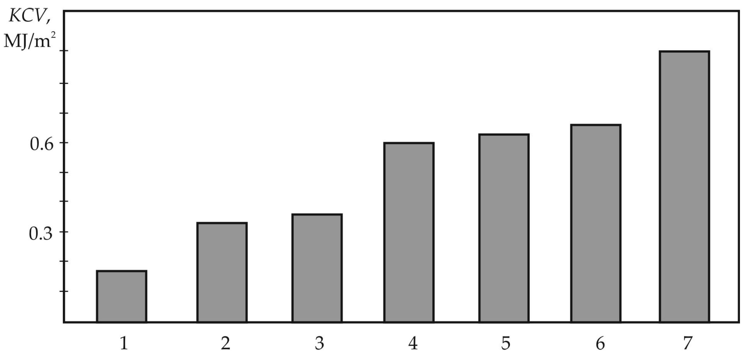
Figure 1. Impact strength of welded metal, forged monolithic metal, and 5-layer metal composite: 1—35W9Cr3VSi, 2—17Cr12Mo2VL, 3—25Cr1Mo1V, 4—10Cr13, 5—12Cr12Mn12SiV, 6—25Cr1Mo1V, and 7—5-layer composite.
Metals 13 01899 g001
Figure 2. Kinetics of fatigue crack propagation in metal with a stress intensity coefficient range ΔK = 23 MPa·m1/2 (refer to Figure 1 for symbols).
Metals 13 01899 g002
Figure 3. Schematic cladding of heterogeneous layered composite (a) and formation of a layered structure of a separate clad roller Cj; (b) S is the direction of laying the clad rollers; l is the mixing zone of adjacent layers; t is the mixing zone of adjacent rollers.
Metals 13 01899 g003
Figure 4. Fractogram of the fracture site in the zone of destruction retardation under cyclic loading (tightening of the cross-section of a compact sample); ×4.
Metals 13 01899 g004
Table 1. Chemical composition of the steels under study.
NSteel GradeContent of Elements, Mass. %
CMnSiCrMoVSP+
125Cr1Mo1V0.320.440.441.570.540.270.0100.0150.30 Ni
217Cr12Mo2V0.170.520.2411.22.080.210.0190.020-
335W9Cr3VSi0.320.800.602.50-0.300.0250.0308.80 W
425Cr5VMoSi0.250.700.805.21.200.500.0200.030-
510Cr130.100.600.6512.2--0.0190.030-
612Cr12Mn12SiV0.1111.850.5012.65-0.300.0220.0280.003 N
Table 2. Mechanical characteristics of the steels under study.
NSteel GradeMechanical Properties
KCV,
MJ/m2
σm,
MPa
σ0.2,
MPa
ψ,
%
δ5,
%
HV
125Cr1Mo1V0.659108005516265
217Cr12Mo2V0.307706155415240
335W9Cr3VSi0.129008102810550
425Cr5VMoSi0.338507804812410
510Cr130.606004405314280
612Cr12Mn12SiV0.655104303328240
Table 3. Hardness and dynamic crack resistance of the layered composite.
NParameterMaterial
18Cr6MnMoVSi18Cr6MnMoVSi–15MnSi–18Cr6MnMoVSi
1Hardness, HV400400210400
2KCV, MJ/m20.42 1.50
3Kcd, MPa∙m1/2 *46.0 65.0
* Average data from 10 Kcd measurements (tests) for each material.
Table 4. Resistance to dynamic destruction of heterogeneous clad layered composites.
NComposition of Composite’s LayersKC,
MJ/m2
KCn,
MJ/m2
KCp, MJ/m2Kcd,
MJ/m2
190CrV (4) 1 + 30CrMnSi (6)0.280.260.0231.1
290CrV (4) + 15kp (3) + 30CrMnSi (3)0.360.280.0855.2
390CrV (4) + 12Cr18Ni10Ti (3) + 30CrMnSi (3)0.480.250.2358.7
490CrV (5) + 12Cr18Ni10Ti (3) + 30CrMnSi (2)0.420.310.11
1—The thickness of the layers is indicated in parentheses, mm.
Table 5. Effect of stress discontinuity on surface crack retardation.
Roller MaterialCladding MaterialStresses, MPa
Type 1Roller SurfaceBoundary with the Base Metal
25Cr1Mo1V12Cr12Mn12SiVσr+300−200
σr + σt+850+300
25Cr1Mo1V10Cr13σr−200+200
σr + σt+300+700
12Cr1Mo1V0Cr17Ni4σr−269−139
σr + σt−119−2
1σr, σt are residual and temporary stresses, respectively.
Disclaimer/Publisher’s Note: The statements, opinions and data contained in all publications are solely those of the individual author(s) and contributor(s) and not of MDPI and/or the editor(s). MDPI and/or the editor(s) disclaim responsibility for any injury to people or property resulting from any ideas, methods, instructions or products referred to in the content.