Abstract
Two austenitic stainless steel (ASS) plates, 304L and 316L, were cold-rolled (304R and 316R) with a 10% reduction in thickness and then subjected to laser welding. Cold rolling caused slight surface hardening and introduced residual tensile stress into the ASS plates. The susceptibility to stress corrosion cracking (SCC) of the welds (304RW and 316RW) was determined using the U-bend test pieces in a salt spray. To highlight the stress concentration at the weld’s fusion boundary (FB), the top weld reinforcement was not ground off before bending. Moreover, micro-shot peening (MSP) was performed to mitigate the SCC of the welds by imposing high residual compressive stress and forming a fine-grained structure. Cold rolling increased the susceptibility of the 304R specimen to pitting corrosion and intergranular (IG) microcracking. Moreover, pitting corrosion and SCC were found more often at the FBs of the 304RW. The corrosion pits of the peened 304RW (304RWSP) were finer but greater in amount than the those of the un-peened one. The results also indicated that the 316L ASS welds with MSP were resistant to the incidence of pitting corrosion and SCC in a salt spray. The better reliability and longer service life of dry storage canisters could be achieved by using 316L ASS for the construction and application of MSP on it.
1. Introduction
Austenitic stainless steels (ASSs) are used to construct canisters to store low- and medium-level nuclear waste [1,2,3,4]. For the building of a nuclear waste canister, machining and/or cold rolling the ASS causes a phase transformation of austenite (γ) to martensite [5,6,7,8], while welding thermal cycles introduce residual tensile stress [9,10] into the final product. The introduction of thermal and mechanical treatments will bring about changes in the physical and chemical properties of the ASSs. The dry storage canisters are proposed to be placed in the nuclear power station near the coastline in Taiwan. With a saline atmosphere and high humidity, the dry storage canister will confront the problem of chloride-induced corrosion/stress corrosion cracking (SCC). In a recent study, synthetic sea salt, Mg chlorides, and particular salt were deposited on a 316L stainless steel (SS) canister to investigate the SCC susceptibility in distinct zones of the weld [1].
Cold rolling and subsequent welding are known to bring out a significant change in the microstructure and corrosion resistance of the ASS welds. Slow strain rate tensile tests in 3.5% NaCl solution show that the tensile elongation and strength of cold-rolled 304 SS decrease by 81% and 42%, respectively, compared with those of the annealed samples [11]. During cyclic loading or cold deformation, the protective film of 316 SS is broken by the induced martensite, resulting in a decrease in the corrosion resistance in chlorine-treated water [12]. The induced α′-martensite is found to be the preferential crack path for the 304 SS reactor serviced in the MgCl2 solution [13]. Moreover, the crack growth along the slip lines of the cold-worked 304L SS is much earlier than that of the annealed sample in 1 M HCl solution [14]. Aging at elevated temperatures or imposing a welding cycle will enhance Cr-carbide precipitation at the grain boundaries of the ASS, which is called sensitization. It is reported that cold rolling will result in severe sensitization at a temperature down to 500 °C [15]. After sensitization at 500 °C, prior cold-worked 304 SS suffered from the intergranular SCC in polythionic acid [16]. Furthermore, cold-rolled, sensitized 304L SS shows high SCC susceptibility in a salt spray at 80 °C [17]. Therefore, cold rolling before welding is expected to cause the ASS weld to be sensitive to SCC.
Surface modifications, and likewise advanced peening processes [18,19,20,21,22,23,24,25,26], are applied to decrease the SCC susceptibility of ASS welds [18]. The severe shot peening of the 304 SS causes significantly refined grains and introduces high residual compressive stress [19]. Ultrasonic nanocrystal surface modification (UNSM) effectively eliminates the tensile stress and imparts compressive stress into 304 welds [20]. Moreover, the fatigue strength/life of 304 SS increases obviously after UNSM treatment [21]. Laser peening is applied to decrease the cracking susceptibility of a 304 SS U-bend sample [22] or retard crack initiation and growth in boiling MgCl2 solution [23]. Laser peening is also reported to mitigate the SCC sensitivity of machined 304 SS in boiling MgCl2 solution [24]. In addition, water jet peening can suppress SCC initiation and increase the fatigue strength of 316L SS [25]. With the proper control of wet micro-shot peening, the increased corrosion resistance of 304 SS is obtained in a chloride solution [26]. Moreover, the occurrence of SCC in 308 weld metal in a primary pressurized water reactor (PWR) environment can be effectively inhibited through polishing in colloidal silica slurry [27]. The combination of refined grain, increased hardness, and induced compressive stress in the peened layer improves the SCC susceptibility of 304 weld metal in 3.5% NaCl solution after high-energy shot peening [28]. The improved corrosion resistance of 316 LN is attributed to the formation of fewer defects and more corrosion-resistant oxides on the peened surface [29]. It is reported that the weld toe curvature of a 304 SS weld can be modified, while cracking at the weld toe is eliminated via ultrasonic peening [30]. In the case of an annealed 304L plate subjected to laser welding, high local strain at the weld’s fusion boundary (FB) shows increased susceptibility to SCC [31]. It is reported that a better fatigue strength of butt welds can be obtained using shot peening and clean blasting [32].
AISI 304 SS jointed via the gas tungsten arc welding (GTAW) process shows high microstructural and mechanical heterogeneity in distinct weld zones [33]. To increase the reliability or prolong the service life, the pitting corrosion/SCC of the dry storage canister in a saline atmosphere must be suppressed or under control. In manufacturing dry storage canisters for spent nuclear fuel, 304L or 316L plates are cold-rolled and then welded via a conventional arc-welding process into a cylinder. The aim of this work is to evaluate the effect of micro-shot peening (MSP) on mitigating the SCC of ASS welds in a salt spray. In this study, cold-rolled 304L and 316L plates were welded using a CO2 laser. SCC of the ASS welds were evaluated by using the U-bend test pieces in a salt spray. MSP was applied on the top weld surface to induce a refined structure and compressive stress field. The damage formed on the surface of the U-bend test pieces was examined using a scanning electron microscope (SEM). Both the phase transformation and refined microstructure near the peened surface were analyzed using electron backscatter diffraction (EBSD). The effect of MSP on the microstructure and residual stress distribution of the peened samples was related to the SCC susceptibility of the investigated samples.
2. Materials and Experimental Procedures
Annealed 304L and 316L SS plates with an initial thickness of 3.0 mm were cold-rolled to 2.7 mm in thickness, which was about a 10% reduction in thickness. The cold-rolled 304L and 316L plates were named 304R and 316R, respectively. The 304R and 316R samples were welded using a CO2 laser in keyhole mode in one pass, designated as 304RW and 316RW, respectively. In the case of the sample with MSP, the “SP” would be added to the designated sample. To highlight the stress concentration at the FB, the top weld reinforcement was not ground off before U-bending in this work. Some U-bend test pieces were shot-peened with iron-based amorphous powders [34] under 200% surface coverage [31]. A MVK-G1500 Vickers micro-hardness tester (Mitutoyo, Kawasaki, Japan) was used to measure the hardness of distinct zones in the weld with a load of 25 gf for 15 sec. A D2 Phaser X-ray diffractometer (XRD, Bruker, Billerica, MA, USA) was used to examine the phase constitutions of the sample, and was operated at 30 kV with 10 mA using a Cu target.
A U-bend sample with dimensions of 10 mm × 120 mm × 2.7 mm was used for SCC evaluation in a salt spray containing 10% NaCl at 80 °C. Based on the ASTM E290 specification [35], the augmented strain on the top surface of the U-bend test piece was about 13.5%, imposed using a die block of 20 mm in diameter. To examine the corroded appearance of the tested pieces, the samples were periodically removed from the environmental chamber and observed using an SZ-STS stereo-microscope (Olympus, Tokyo, Japan). The SCC tests in a salt spray were terminated after a 672 h duration.
The µ-X360s (Pulstec, Shizuoka, Japan), a residual stress analyzer, was applied to determine the residual stress distribution in U-bend samples with or without shot peening. The standard settings of the µ-X360s X-ray source used Cr target Kα radiation (wavelength 2.291 Å) at an X-ray tube voltage of 30 kV with a 1.5 mA current. The beam spot for measuring stress was 2.0 mm in diameter. The device for measuring residual stress is based on the cos α method. The distribution of residual stress in the thickness direction was obtained by removing the surface layer of the sample using an EP-3 electrochemical polisher (Pulstec, Shizuoka, Japan). The corroded appearance of the U-bend specimens after salt spraying was observed using an S-3400N SEM (Hitachi, Tokyo, Japan). The strain-induced α′-martensite and refined microstructure formed on the shot-peened layer were explored using a NordlysMax2 EBSD (Oxford Instruments, Abingdon, UK) detector. Moreover, the strain distribution of the investigated specimen was determined using the HKL Channel 5 software (Oxford Instruments, Abingdon, UK) to analyze the original data acquired using the EBSD detector.
3. Results
3.1. Macro-Views of the Tested Samples
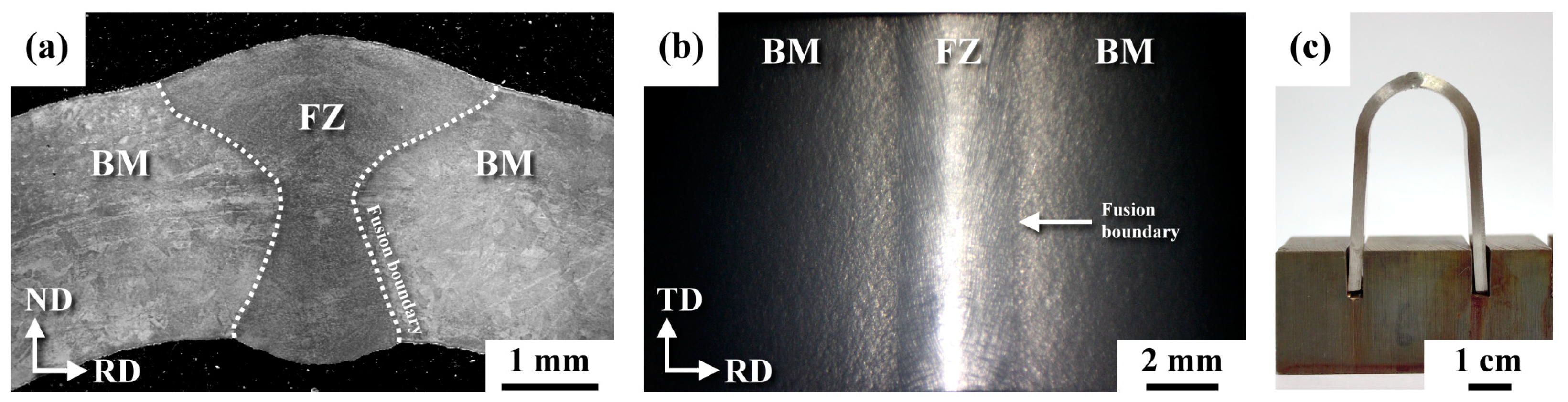
Figure 1 shows the macro-views of the U-bend samples for the salt spray tests; the cold-rolled SS plates were welded using a CO2 laser. As shown in Figure 1a, the augmented strain was about 13.5% on the external surface of the smooth sample. In this work, the U-bend weld comprised a weld reinforcement in the middle of the test piece (Figure 1a). The top view of the U-bend weld is shown in Figure 1b, showing the discontinuous profile at the weld’s FB (indicated by the arrow). The lateral view of the U-bend weld is shown in Figure 1c. Overall, the weld reinforcement of an autogenous laser weld was still low compared to that of the conventional arc weld. In the case of the shot-peened sample, MSP was applied on the top surface of the U-bend sample, which covered the entire fusion zone (FZ), the narrow heat-affected zone (HAZ), and the base metal (BM). The construction of the dry storage canister for spent fuels in Taiwan is achieved by joining a cold-rolled 304/304L plate via the arc welding process into a cylinder of about 1.8 m in diameter. The new specification for constructing the dry storage canister requires grinding off all the weld reinforcements and avoiding the undercut, which reduces the stress concentration and accumulation of contaminants therein.
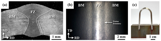
Figure 1.
Macroscopic photos of (a) the U-bend weld in a cross-sectional view, (b) the top appearance of the U-bend weld, and (c) a lateral view of the U-bend sample for the salt spray (BM: base metal; FZ: fusion zone).
3.2. XRD Spectrums of the Cold-Rolled Samples with and without MSP
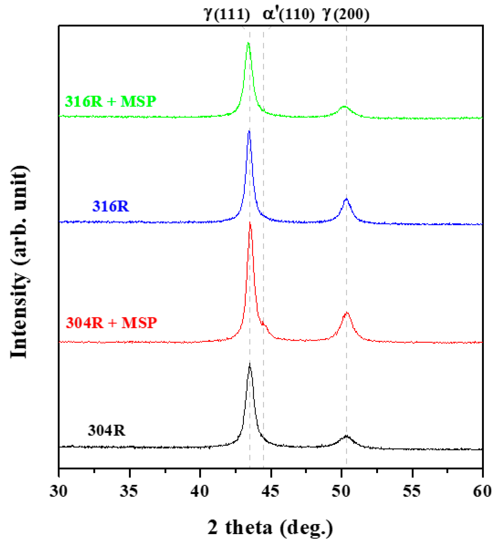
The annealed 304L and 316L plates were non-ferromagnetic, i.e., the ferrite number (FN) determined according to the ferrite scope was nearly zero. The cold rolling of unstable ASSs was expected to cause strain hardening and strain-induced martensitic transformation. With a 10% reduction in thickness after cold rolling, a minor increase in FN from 0 to 0.7 was found for the 304R and about 0.1 for the 316R samples. The XRD spectrums of the cold-rolled plates in the as-rolled and shot-peened conditions are shown in Figure 2. The XRD results indicated that no distinguishable ferrite phase was observed in the 304R and 316R samples. After peening, a slightly broadened γ peak was seen in the 304RSP sample, which could be related to the formation of a certain amount of α′-martensite mixed with the γ matrix. In contrast, γ was still the predominant phase in the 316RSP sample. The ferrite scope and XRD spectrum confirmed that 316L SS had high resistance to strain-induced transformation relative to that of 304L SS. It is reported that plastic deformation induced by MSP assisted austenite in martensite transformation and strain hardening within a narrow depth [34]. The microstructure of the cold-rolled ASSs showed traces of slip lines within the granular austenite matrix, especially around the external surface, which were not seen in the annealed plates and would be confirmed in the following EBSD analysis. As reported previously [31], the FZ of the 304L and 316L welds had a FN of about 1.78 and 0.54, respectively. The high FN of the 304L FZ was associated with the skeletal microstructure with vermicular ferrite (δ) within the solidified matrix. In contrast, cellular dendrites with less ferrite are formed in the 316L FZ of low FN [31].
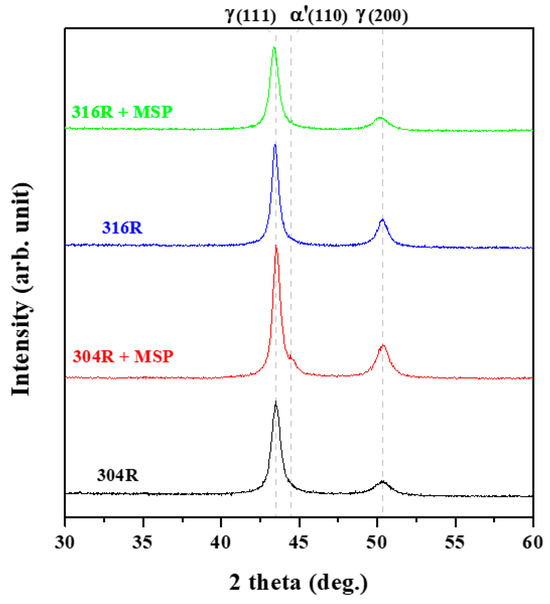
Figure 2.
The XRD spectrums of the cold-rolled ASSs in the as-rolled and shot-peened conditions.
3.3. The Micro-Hardness Profiles of the Shot-Peened Welds
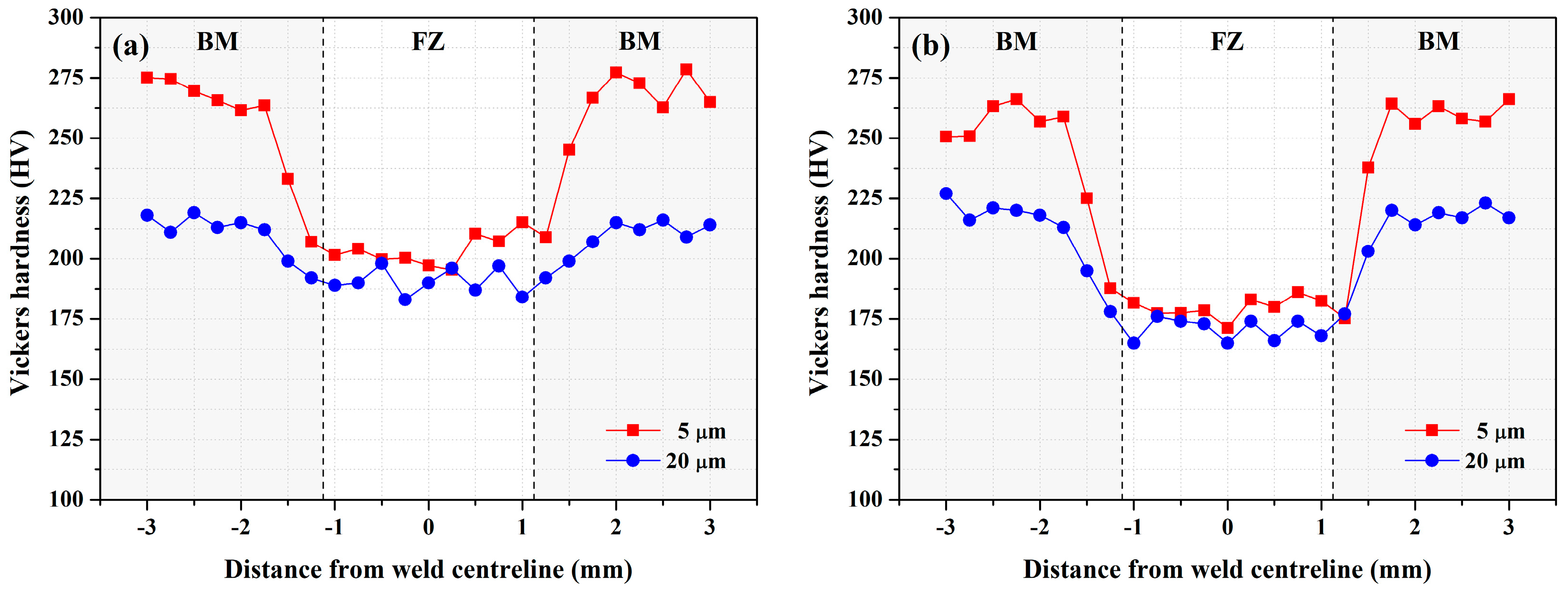
The micro-hardness profiles in distinct zones of two welds are displayed in Figure 3. The micro-hardnesses were determined from one side of the BM across the FZ to the other side of the BM. As shown in Figure 3, each hardness measurement was performed at 5 and 20 μm from the outer surface of the cold-rolled plates in the as-welded condition. Cold rolling resulted in slight strain hardening around the surface of the SS plate. The peak hardness in the cold-rolled plate decreased from about HV 275 to HV 225, increasing the depth from 5 to 20 μm from the outmost surface. Because of the imposed strain-hardening of the cold-rolled plate, the hardness of the FZ was the lowest among the distinct zones in the weld, regardless of the welds (Figure 3). At a depth of 20 μm away from the top surface of the plate, the difference in hardness between the FZ and the BM of the two welds became less.
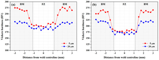
Figure 3.
The hardness distributions in distinct zones of the (a) 304RW and (b) 316RW samples at depths of 5 and 20 μm from the top surface of the cold-rolled plates.
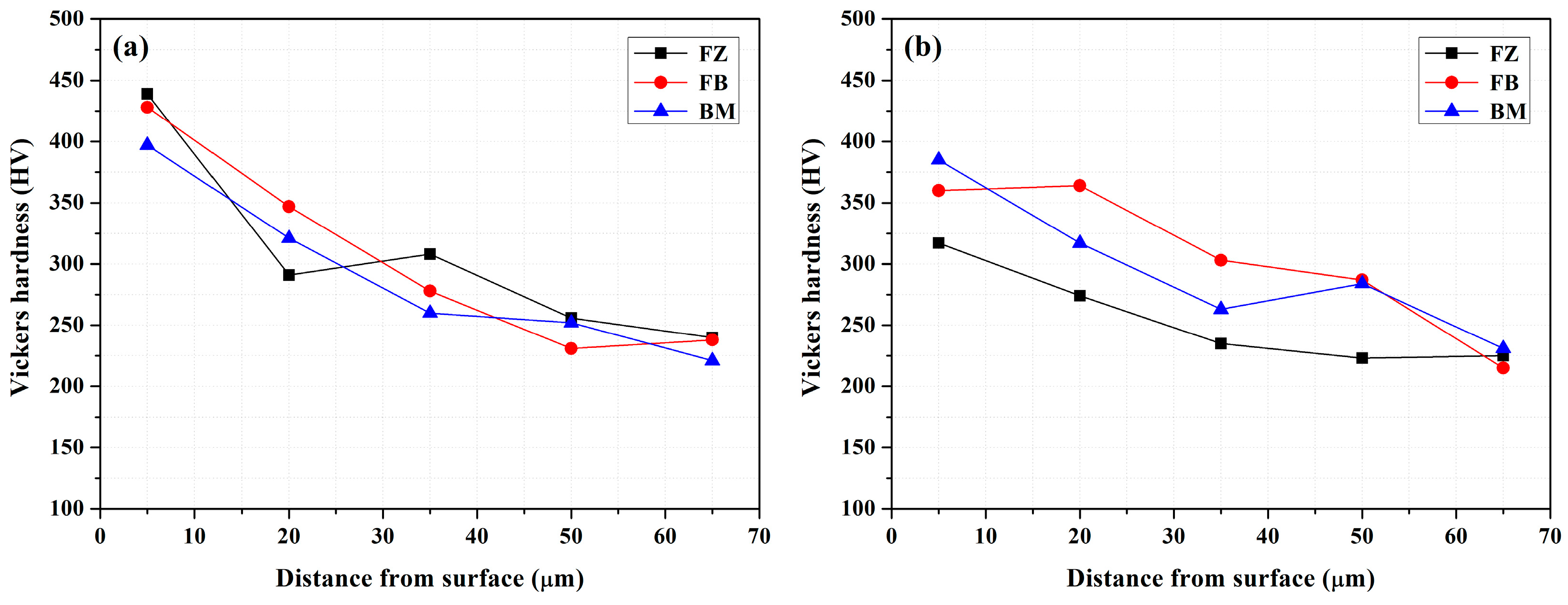
Figure 4 demonstrates the variations in micro-hardness along the thickness direction in three different zones of the shot-peened welds from the outmost surface to the interior after MSP. According to the hardness profiles, the peen-affected depth was about 70 μm, regardless of the welds after MSP. At a depth of about 70 μm, the FZ, FB, and BM all had similar hardness values despite the welds. Around the peened layer, the three different zones in the 304RWSP sample were harder than those in the 316RWSP sample, one in each group after MSP. A marked drop in hardness from about HV 400 to HV 200 was obtained within a 70 μm depth for the shot-peened weld. Such a high outmost hardness in the FZ, FB, and BM might accompany a great decrease in the pitting corrosion and SCC resistance.
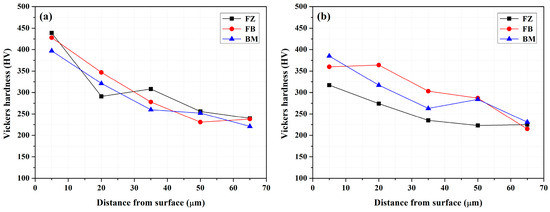
Figure 4.
The changes in micro-hardness in the thickness direction in the BM, FB, and FZ of the (a) 304RWSP and (b) 316RWSP samples from the shot-peened surface to the interior of the welds.
3.4. Surface Appearance of the Tested Samples after Salt Spray
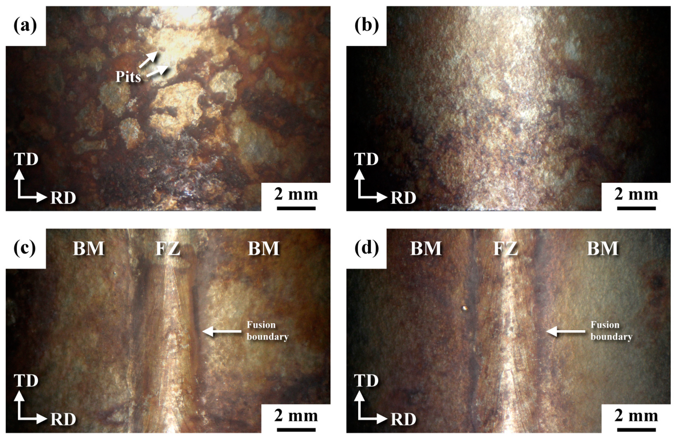
The surface appearances of distinct samples after salt spraying are illustrated in Figure 5. Compared with the annealed plate [31], severe rusting in different patches with deep pits was seen in the 304R after salt spraying (Figure 5a). However, rusting in 16R after the test was moderate (Figure 5b) compared to that in 304R. Thus, cold rolling inevitably decreased the corrosion resistance of the ASS in a salt spray. The top appearance of the U-bend welds is shown in Figure 5c,d. The 304RW (Figure 5c) sample rusted more heavily than did the 316RW sample (Figure 5d). The FBs of the weld were corroded more severely than were the other zones of the weld. The discontinuous profile at the FB might assist the accumulation of harmful species therein, resulting in heavy rusting. Moreover, the imposed welding heat on the cold-rolled SS plate would enhance the occurrence of sensitization in the HAZ of an ASS weld [15,16]. Overall, the macro-appearance of the U-bend samples after salt spraying was similar in each group with or without shot peening. However, the corrosion pits and fine ditches were less likely to form in the 316RWSP sample.

Figure 5.
The macro-surface appearance of the U-bend samples for the (a) 304R, (b) 316R, (c) 304RW, and (d) 316RW samples after salt spraying.
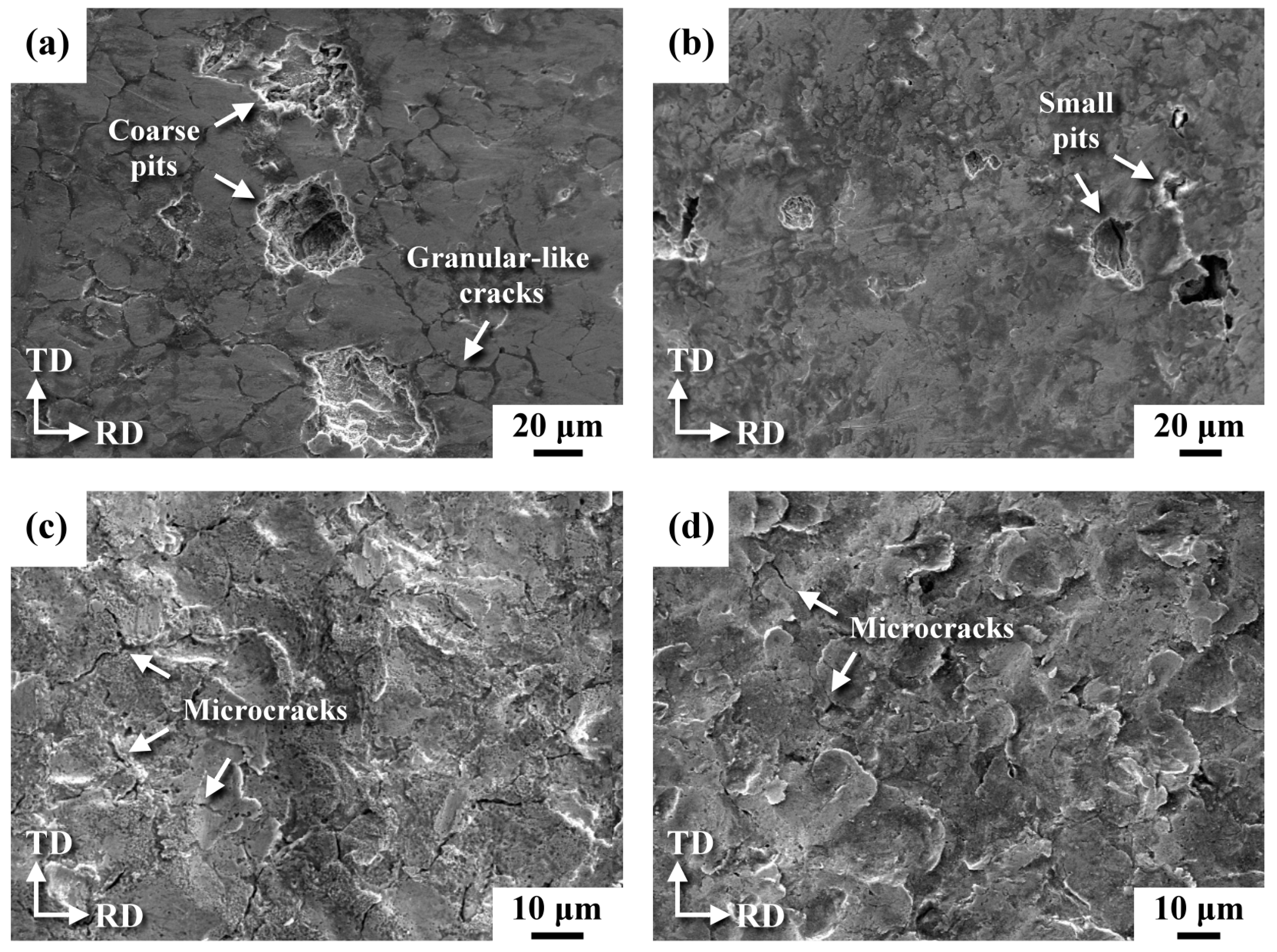
SEM micrographs displaying the surface morphology of the U-bend test pieces after salt spraying are shown in Figure 6. The 304R sample corroded severely, and showed granular-like cracks inter-dispersed with coarse pits (Figure 6a). In contrast, no granular-like cracks and small corrosion pits were seen in the 316R sample after salt spraying (Figure 6b). After MSP, the corroded surface of the 304RSP sample showed uneven dent sizes inter-dispersed with numerous microcracks (Figure 6c). In contrast, less rusty dents with sparse microcracks were observed in the 316RSP sample (Figure 6d). It was obvious that MSP was able to prevent the formation of coarse corrosion pits in the cold-rolled ASS.

Figure 6.
SEM micrographs showing the surface appearance of the (a) 304R, (b) 316R, (c) shot-peened 304R (304RSP), and (d) shot-peened 316R (316RSP) samples after salt spraying.
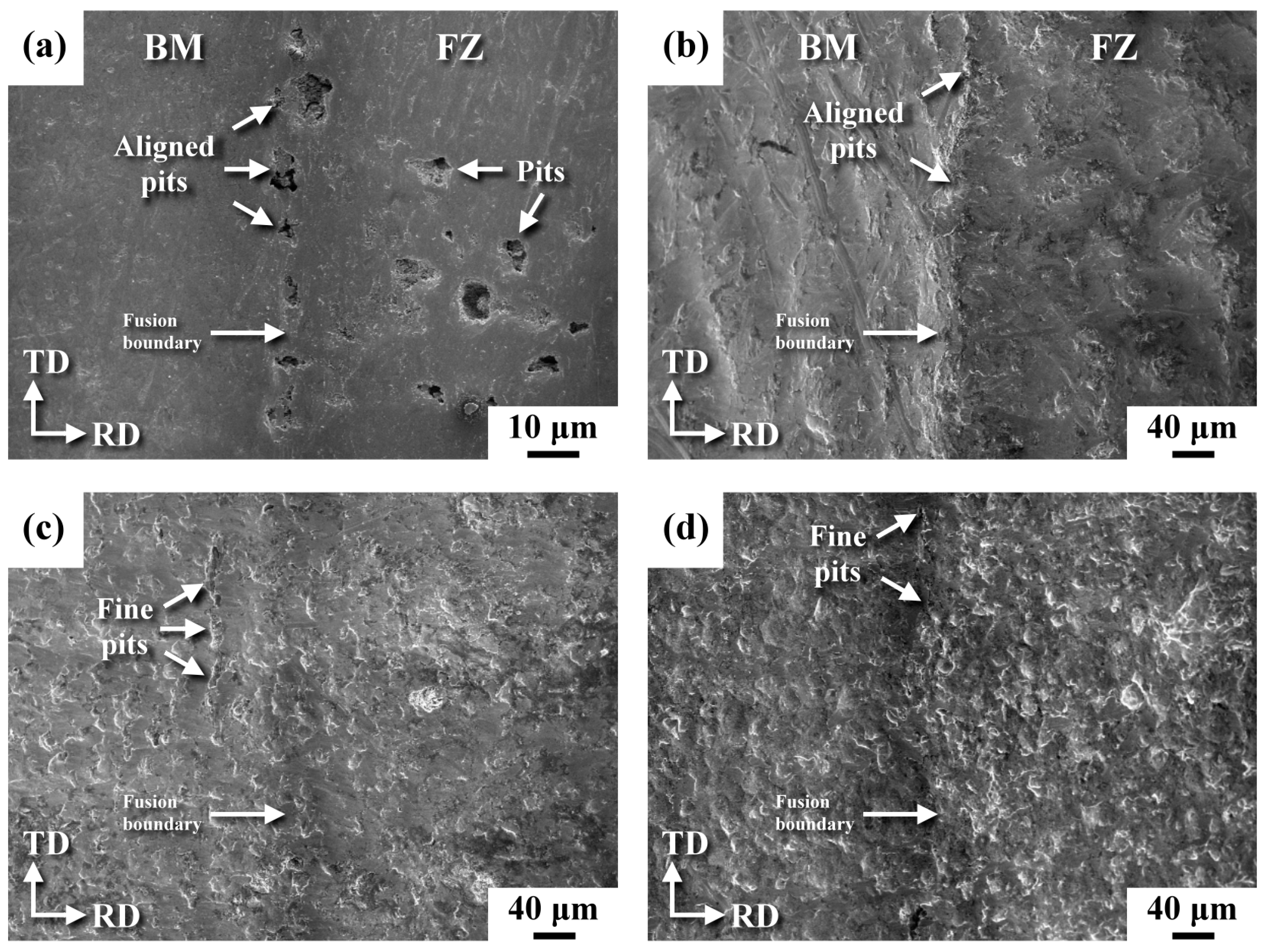
Figure 7 shows the SEM morphology of the U-bend welds with or without MSP. Without MSP, the FB of the 304RW sample consisted of aligned corrosion pits, and the FZ was also damaged by the uneven sizes of the corrosion pits (Figure 7a). Corrosion pits were less likely to be seen in the 316RW sample (Figure 7b) than they were in the 304RW sample. Overall, corrosion damage seemed heavier at the FB than at other zones in the 316RW sample. With MSP, numerous fine dents and pits were formed around the FB of the 304RWSP sample after salt spraying (Figure 7c). The corrosion pits of the peened 304RW sample (304RWSP) were finer but greater in amount than those in the un-peened one. Relatively coarse pits were found occasionally in the FZ of the 304RWSP sample. The feature of impact dents formed on the peened 316RW (316RWSP) surface was still visible in distinct zones (Figure 7d), which implied that there was a less corroded surface after salt spraying. With the discontinuous profile, the FB of the 316RWSP sample remained as the weak sites for SCC relative to other zones. Overall, the better reliability and longer service life of dry storage canisters could be achieved using 316L SS for the construction and application of MSP.

Figure 7.
SEM morphologies of the (a) 304RW, (b) 316RW, (c) shot-peened 304RW (304RWSP), and (d) shot-peened 316RW (316RWSP) samples after salt spraying.
3.5. XRD Analysis of Residual Stress in the Cold-Rolled Plates
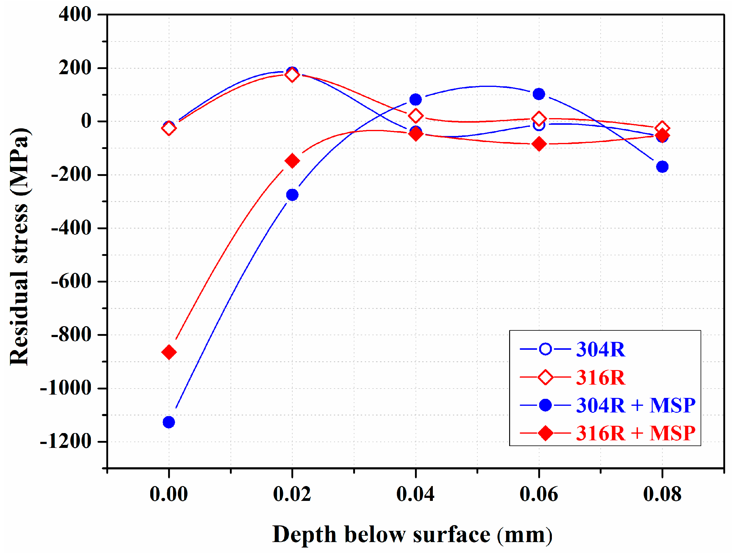
Residual stress profiles along the thickness direction from the top to the interior of the 304R and 316R samples with or without MSP are shown in Figure 8. In prior work [31], residual stress profiles of the as-welded FZs along the thickness direction were determined after grinding off the weld reinforcement. Peak tensile stress lower than 150 MPa was present in the as-welded FZs, possibly due to the low heat input of laser welding [31]. The tensile stress state of the as-welded FZ changed into a compressive state of about 750 MPa after MSP [31]. It was expected that residual tensile stress would increase the SCC susceptibility of the investigated sample, whereas residual compressive stress would mitigate the occurrence of SCC. As shown in Figure 8, the residual stress profiles of the 304R and 316R samples were similar. The residual stress was in tension on the subsurface of the 304R and 316R samples, and the peak stress was about 200 MPa in tension. Residual tensile stress on the 304R and 316R samples was expected to increase their SCC susceptibility. However, a residual compressive stress of over −800 MPa was obtained for the peened 316R sample (316R + MSP) and that of −1100 MPa was obainted for the peened 304R sample (304R + MSP). Such high induced residual compressive stress after MSP could be related to the shot peening of the cold-rolled plate and the induced martensitic transformation in the peened zone. As shown in Figure 8, the narrow compressive stress field could be associated with the intense but limited depth of plastic deformation caused by MSP. In this work, the discontinuous profile made the stress measurements around the FZ impractical. However, introducing residual compressive stress via peening the weld was anticipated to lower the SCC susceptibility in different zones of the ASS weld.
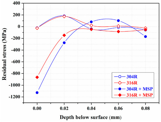
Figure 8.
The residual stress profiles of the cold-rolled plates in the as-rolled and shot-peened conditions, determined via XRD.
3.6. EBSD Analysis of the U-Bend Welds
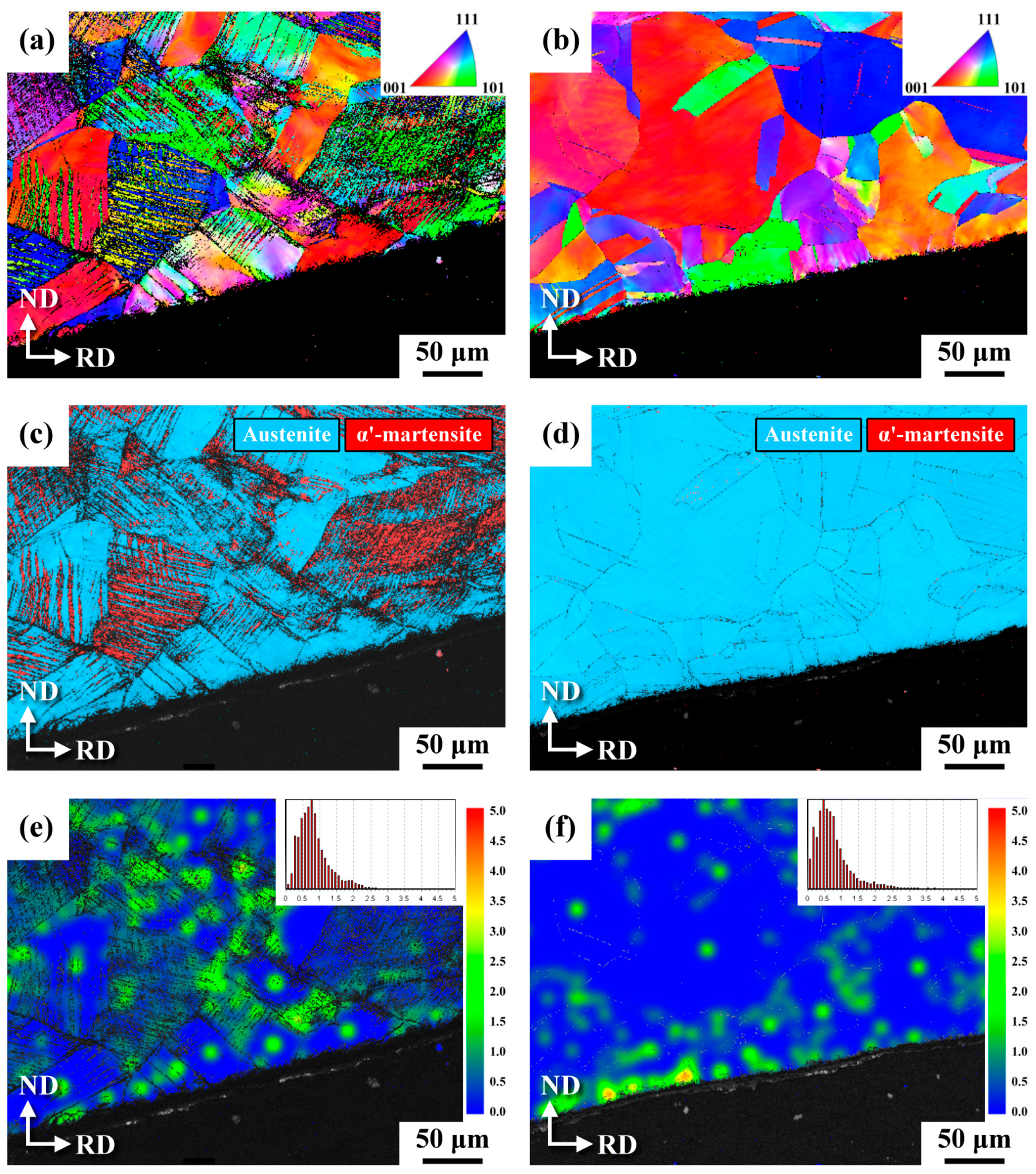
Figure 9 is the EBSD analysis showing the outermost microstructures in a cross-sectional view in the BM zone of the peened U-bend weld. The results indicated that extensive slips (Figure 9a) and a great amount of induced α′-martensite (Figure 9c) were formed in the BM zone of the 304RW sample relative to those of the 316RW sample (Figure 9b,d). Compared with the counterpart sample in the annealed state in prior work [31], prior cold rolling indeed assisted in the occurrence of strain-induced transformation in the BM of this work. Those patches with dense slip bands were also accompanied by the presence of α′-martensite (Figure 9c) and high local strain (Figure 9e). In contrast, scarce slips (Figure 9b) and trivial martensite (Figure 9d) formed in the BM zone of the 316RWSP sample assured that the 316L was much more stable and resistant to plastic deformation. Although all the external surfaces of the U-bend weld had been shot-peened, only a very thin surface layer showed a refined structure and sparse martensite in the BM zone of the weld. It was deduced that the strain hardening caused by the prior cold rolling of the substrate impeded the further plastic deformation of the ASS during MSP, resulting in a limited peening effect being shown.

Figure 9.
EBSD (a,b) IPF maps, (c,d) phase maps, and (e,f) strain maps in the cross-sectional view of the U-bend samples in the BM of (a,c,e) the 304RWSP sample; (b,d,f) the 316RWSP samples.
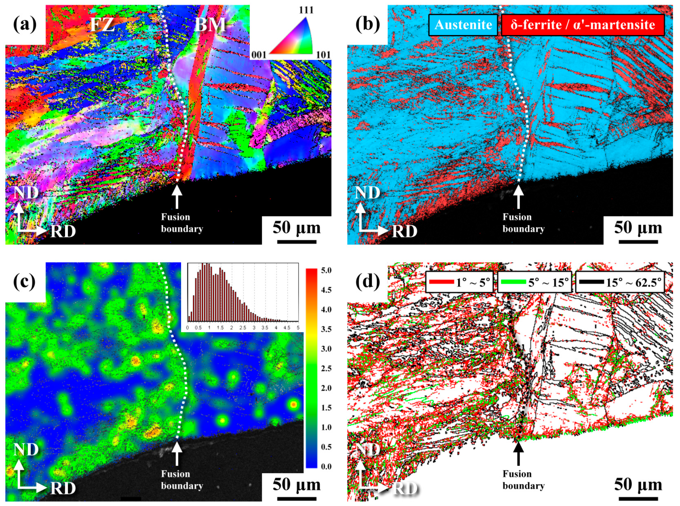
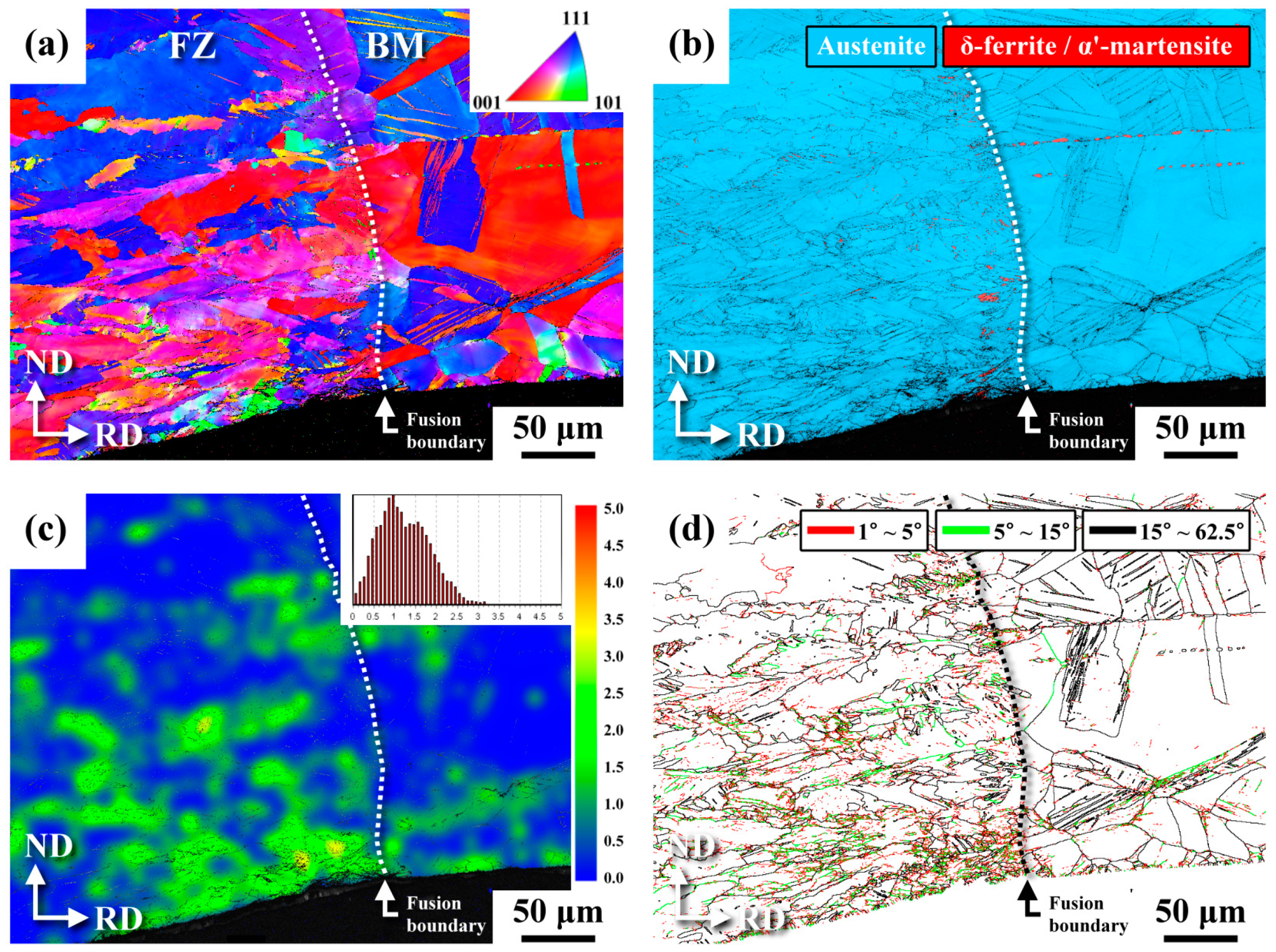
After MSP, the EBSD investigations around the FB of the peened U-bend 304RW (304RWSP) sample in a cross-sectional view are shown in Figure 10. As revealed in Figure 10a,b, the zone near the FB on the BM side comprised similar microstructures to those of the BM, shown in Figure 9a,c. Owing to the coarse granular structure of the 304L substrate, the slip bands or lath martensite on the BM side were coarser and longer than those in the FZ (Figure 10a,b). It could be deduced that the fine δ-ferrite, solidified skeletal structure, and induced fine martensite in the FZ were responsible for a finer lath microstructure than that of the zone on the BM side. It was noticed that the outer surface of the FZ was covered by thin but dense martensite (Figure 10b), whereas this was hard to observe on the BM side. Therefore, the FZ was more likely to undergo strain-induced transformation under shot peening than was the cold-rolled substrate. Moreover, the strain map (Figure 10c) also revealed that the FZ had high local strain relative to that of the zone on the BM side. The grain boundary (GB) map (Figure 10d) showed the grain boundary characteristics of the inspected sample. Low-angle grain boundaries (LAGBs) include the martensite lath and high-density dislocation-tangled boundaries within the matrix. High-angle grain boundaries (HAGBs) are associated with γ, δ-ferrite, and α′-martensite boundaries, having misorientations of 15–62.5° relative to the adjacent grains. In Figure 10d, the LAGBs are colored with red (1–5°) and green (5–15°) lines; HAGBs (15–62.5°) are colored black. The FZ had a higher density of LAGBs than did the zone on the BM side, implying that the slips or dislocation motions were more likely to occur during straining. Those fine dark spots could be related to the induced α′-martensite or δ-ferrite. The peened surface on the BM side was noted to have a very thin layer of refined structure with dense LAGBs (Figure 10d).

Figure 10.
EBSD (a) IPF map, (b) phase map, (c) strain map, and (d) GB map of the U-bend sample around the FZ of the 304RWSP sample in a cross-sectional view.
The EBSD investigations around the FB of the U-bend peened 316RW (316RWSP) sample in a cross-sectional view are shown in Figure 11. The FZ also had a finer structure than did the zone on the other side of the FB (Figure 11a). According to the phase map (Figure 11b), the ferromagnetic phase present in the FZ of the 316RWSP sample was less and finer than that in the 304RWSP sample. As mentioned in the text, thin but dense α′-martensite was obtained in the heavily peened layer in the FZ of the 304RWSP sample. However, only rare martensite was detected on the top surface of the FZ in the 316RWSP sample under the same peening (Figure 11b). The result indicated that strain-induced transformation occurred less, even in the solidified 316L sample. The strain map (Figure 11c) also displayed that the FZ of the 316RW sample was of a high strain relative to that of the other zones, which should be inferior to the SCC resistance. The GB map of the 316RW sample (Figure 11d) showed that the FZ consisted of a refined structure or high GB densities relative to those of the zone on the BM side. Moreover, a quite difference in LAGBs in the FZ of the 304RW (Figure 10d) and 316RW (Figure 11d) samples was seen, which could be associated with fewer dislocation motions/slips in the latter during bending.
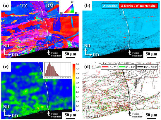
Figure 11.
EBSD (a) IPF map, (b) phase map, (c) strain map, and (d) GB map of the U-bend sample around the FZ of the 316RWSP sample in a cross-sectional view.
4. Discussion
The resistance to pitting corrosion and SCC is the great concern of the dry canister for storing spent nuclear fuels near the coastline. The combination of deformation-induced martensite and a large amount of MnS inclusion is reported to deteriorate the corrosion resistance of a 304 SS rod in a chloride environment [36]. Thus, the machining process, welding, and microstructural heterogeneity present in the original SS plate may lower the reliability of the canister during long-term service. In 1 M NaCl + 0.5 M HCl, the weld metal (WM) and HAZ of a 304 GTAW weld are more sensitive to pitting corrosion than is the BM [37]. The HAZ of a 304 SS weld is pointed out to have high sensitivity to SCC in chloride solution [38,39]. Among the distinct zones in a 316 SS weld exposed to synthetic sea salt and MgCl2 deposits, the HAZ showed high SCC relative to the WM and BM due to the combination of tensile residual stress and plastic strain [1]. Therefore, particular concerns should be addressed to mitigate pitting corrosion/SCC in the HAZ of a weld.
In this work, annealed 304L and 316L SS plates were cold-rolled to about a 10% reduction in thickness. The XRD spectrums (Figure 2) showed the results of little austenite transformation to martensite even for the cold-rolled 304L sample but caused slight strain-hardening. Residual stress profiles along the thickness direction from the top to the interior of the 304R and 316R samples were determined (Figure 8). The surface residual stress of the 304R and 316R was in tension, and the peak tensile stress of those two samples was about 200 MPa. Therefore, cold rolling introduced residual tensile stress into the SS plates, which was expected to increase the SCC susceptibility. In contrast, MSP reversed the residual stress profiles of the cold-rolled plates. Residual compressive stress over −800 MPa was introduced for the peened 316R (316RSP) sample and that of −1100 MPa was introduced for the peened 304R sample (304RSP). The corrosion resistance of the HAZ of the tungsten inert gas (TIG)-welded 304 SS weld in NaCl solution was improved by increasing the welding current and number of passes; the causes are related to the decreased or relaxed residual stresses [40]. Therefore, it was practical to apply MSP after welding to reverse the surface tensile stress into compressive stress to lower the SCC susceptibility of an ASS weld in a chloride-containing environment.
The severe rusting of the 304R sample, which showed granular-like cracks inter-dispersed with coarse pits (Figure 6a), occurred after salt spraying, whereas no granular-like cracks and fine corrosion pits were seen in the 316R sample. The FB of the 304RW sample consisted of aligned corrosion pits, and the FZ was also damaged by uneven sizes of corrosion pits (Figure 7a). Moreover, the 304RSP sample displayed irregular-sized dents inter-dispersed with numerous microcracks (Figure 6c). In contrast, less corroded dents with sparse microcracks were observed in the 316RSP sample (Figure 6d). With MSP, numerous fine dents and pits were formed around the FB of the 304RWSP sample after salt spraying (Figure 7c). The corrosion pits of the peened 304RW sample were finer but greater in amount than those of the un-peened one. It was obvious that the formation of coarse pits and the linkage of coarse pits in a microcrack at the FB of an ASS weld could be mitigated by MSP. Therefore, applying MSP on a 316L SS canister would be better for storing spent nuclear fuels, and showed increased reliability for long-term service in a chloride-containing environment.
The EBSD analysis revealed that those patches with dense slip bands were also accompanied by the presence of α′-martensite (Figure 9c) and high local strain (Figure 9e). The FZ was shown to be of high shrinkage strain (Figure 9e). It was known that α′-martensite and high local strain were harmful to pitting corrosion and the SCC resistance of an ASS. The top FZ surface of the 304RWSP sample was covered with dense but thin α′-martensite, which might have impaired the pitting corrosion and SCC resistance. However, MSP resulted in the formation of a refined microstructure and the introduction of tremendous residual compressive stress in the peened zone of the ASS, which were beneficial to impeding the initiation of pitting corrosion and SCC. Overall, the harmful effect of α′-martensite on the SCC resistance of an ASS was overcome by the positive effect of a refined structure and residual compressive stress after MSP. Therefore, the SCC of the ASS welds could be effectively retarded via MSP, particularly for the 316L SS weld. High local strain at the FB was the reason for the high SCC cracking in the ASS weld. Ultrasonic peening is applied to modify weld toe geometry and introduces residual compressive stress into a 304 weld [30], which makes the corrosion resistance even better than that of the BM. MSP could not correct the geometry of the weld toe. Without grinding off the weld reinforcement, MSP was still able to lower the SCC susceptibility of two ASS welds in which the substrate was originally in the cold-rolled condition. Therefore, the application of MSP to reduce the SCC susceptibility of the canister for the storage of spent nuclear fuels was practical. In addition, the 316 canister with MSP would show better service reliability to impede the incidence of pitting corrosion and SCC in a chloride-containing environment.
5. Conclusions
- With a 10% reduction in thickness after cold rolling, even the 304R sample showed slight strain hardening and a phase transformation. However, the induced residual tensile stress after cold rolling increased the pitting corrosion and SCC susceptibility of the ASS plates. The results indicated that MSP reversed the residual stress profiles of the cold-rolled plates, which improved the pitting corrosion and SCC resistance. Severe rusting in the 304R sample was seen after salt spraying, and it showed granular-like cracks inter-dispersed with coarse corrosion pits. After MSP, the corroded surface of the peened 304R sample showed distinct dent sizes inter-dispersed with numerous microcracks.
- Without MSP, the FB of the 304RW sample consisted of aligned corrosion pits, whereas uneven sizes of corrosion pits also damaged the FZ. With MSP, numerous fine dents and pits were found around the FB of the 304RWSP sample after salt spraying. EBSD analysis displayed that the peened FZ surface of the 304RWSP sample was covered with dense but thin α′-martensite, which increased the SCC susceptibility. However, the refined microstructure and high compressive residual stress in the FZ of the 304RWSP sample were beneficial in impeding the initiation of pitting corrosion and SCC. Moreover, the impact dents formed on the peened 316RW (316RWSP) surface after salt spraying were still visible in distinct zones, which implied better resistance to pitting corrosion and SCC.
- The presence of high compressive residual stress and the fine-grained structure in the peened ASS weld could increase the pitting corrosion resistance and decrease the SCC susceptibility. However, shot peening enhanced the martensitic transformation of the unstable ASS and increased surface roughness, which were harmful to the corrosion performance. The results indicated that MSP could lower the pitting corrosion and SCC susceptibility of an ASS weld. Based on the material essential, the better reliability and longer service life of dry storage canisters could be achieved using 316L SS for the construction and application of MSP.
Author Contributions
Investigation, C.-Y.K. and T.-C.C.; Data Curation, C.-Y.K. and T.-C.C.; Writing—Review & Editing, T.-C.C. and R.-K.S.; Supervision, R.-K.S.; Visualization, R.-K.S.; Conceptualization, Methodology, Resources, Writing—Original Draft, Project administration, L.-W.T. All authors have read and agreed to the published version of the manuscript.
Funding
This research was funded by the Ministry of Science and Technology, R.O.C. (Contract No. MOST 109-2221-E-019-023-MY3).
Data Availability Statement
The data presented in this study are available on request from the corresponding author. The data are not publicly available due to privacy concerns.
Acknowledgments
The authors would like to thank Likuan Technology Corp. for the great help in determining the residual stress of the investigated sample and Vincent Vacuum Tech. for performing MSP.
Conflicts of Interest
The authors declare no conflict of interest.
References
- Dong, P.; Scatigno, G.G.; Wenman, M.R. Effect of Salt Composition and Microstructure on Stress Corrosion Cracking of 316L Austenitic Stainless Steel for Dry Storage Canisters. J. Nucl. Mater. 2021, 545, 152572. [Google Scholar] [CrossRef]
- Vehovar, L.; Tandler, M. Stainless steel containers for the storage of low and medium level radioactive waste. Nucl. Eng. Des. 2001, 206, 21–23. [Google Scholar] [CrossRef]
- Kain, V.; Sengupta, P.; De, P.K.; Banerjee, S. Case reviews on the effect of microstructure on the corrosion behavior of austenitic alloys for processing and storage of nuclear waste. Metall. Mater. Trans. A 2005, 36, 1075–1084. [Google Scholar] [CrossRef]
- Kim, S.; Kim, G.; Oh, C.Y.; Song, S. Pitting and Localized Galvanic Corrosion Characteristics of Gas Tungsten Arc Welded Austenitic Stainless Steel. Met. Mater. Int. 2022, 28, 2448–2461. [Google Scholar] [CrossRef]
- Acharyya, S.G.; Khandelwal, A.; Kain, V.; Kumar, A.; Samajdar, I. Surface working of 304L stainless steel: Impact on microstructure, electrochemical behavior and SCG resistance. Mater. Charact. 2012, 72, 68–76. [Google Scholar] [CrossRef]
- Zhang, W.; Wang, X.; Hu, Y.; Wang, S. Quantitative Studies of Machining-Induced Microstructure Alteration and Plastic Deformation in AISI 316 Stainless Steel Using EBSD. J. Mater. Eng. Perform. 2018, 27, 434–446. [Google Scholar] [CrossRef]
- Tsay, L.W.; Lin, Y.J.; Chen, C. The effects of rolling temperature and sensitization treatment on the sulfide stress corrosion cracking of 304L stainless steel. Corros. Sci. 2012, 63, 267–274. [Google Scholar] [CrossRef]
- Odnobokova, M.; Belyakov, A.; Enikeev, N.; Kaibyshev, R.; Valiev, R.Z. Microstructural Changes and Strengthening of Austenitic Stainless Steels during Rolling at 473 K. Metals 2020, 12, 1614. [Google Scholar] [CrossRef]
- Katsuyama, J.; Tobita, T.; Itoh, H.; Onizawa, K. Effect of Welding Conditions on Residual Stress and Stress Corrosion Cracking Behavior at Butt-Welding Joints of Stainless Steel Pipes. J. Press. Vessel Technol. 2012, 134, 021403. [Google Scholar] [CrossRef]
- Wu, X. On residual stress analysis and microstructural evolution for stainless steel type 304 spent nuclear fuel canisters weld joint: Numerical and experimental studies. J. Nucl. Mater. 2020, 534, 152131. [Google Scholar] [CrossRef]
- He, S.; Jiang, D. Effect of the Degree of Rolling Reduction on the Stress Corrosion Cracking Behavior of SUS 304 Stainless Steel. Int. J. Electrochem. Sci. 2018, 13, 1614–1628. [Google Scholar] [CrossRef]
- Solomon, N.; Solomon, I. Effect of deformation-induced phase transformation on AISI 316 stainless steel corrosion resistance. Eng. Fail Anal. 2017, 79, 865–875. [Google Scholar] [CrossRef]
- Park, I.; Kim, E.Y.; Yang, W.J. Microstructural Investigation of Stress Corrosion Cracking in Cold-Formed AISI 304 Reactor. Metals 2021, 11, 7. [Google Scholar] [CrossRef]
- Ghosh, S.; Kain, V. Effect of surface machining and cold working on the ambient temperature chloride stress corrosion cracking susceptibility of AISI 304L stainless steel. Mater. Sci. Eng. A 2010, 527, 679–683. [Google Scholar] [CrossRef]
- Kain, V.; Chandra, K.; Adhe, K.N.; De, P.K. Effect of cold work on low-temperature sensitization behaviour of austenitic stainless steels. J. Nucl. Mater. 2004, 334, 115–132. [Google Scholar] [CrossRef]
- Singh, R. Influence of cold rolling on sensitization and intergranular stress corrosion cracking of AISI 304 aged at 500 °C. J. Mater. Process. Technol. 2008, 206, 286–293. [Google Scholar] [CrossRef]
- Li, W.J.; Young, M.C.; Lai, C.L.; Kai, W.; Tsay, L.W. The effects of rolling and sensitization treatments on the stress corrosion cracking of 304L stainless steel in salt-spray environment. Corros. Sci. 2013, 68, 25–33. [Google Scholar] [CrossRef]
- Lu, Z.; Xu, F.; Tang, C.; Cui, Y.; Xu, H.; Mao, J. Stress Corrosion Cracking Susceptibility of 304 Stainless Steel Subjected to Laser Shock Peening without Coating. J. Mater. Eng. Perform. 2021, 30, 7163–7170. [Google Scholar] [CrossRef]
- Liu, H.; Wei, Y.; Tan, C.K.I.; Ardi, D.T.; Tan, D.C.C.; Lee, C.J.J. XRD and EBSD studies of severe shot peening induced martensite transformation and grain refinements in austenitic stainless steel. Mater. Charact. 2020, 168, 110574. [Google Scholar] [CrossRef]
- Ye, C.; Telang, A.; Gill, A.; Wen, X.; Mannava, S.R.; Qian, D.; Vasudevan, V.K. Effects of Ultrasonic Nanocrystal Surface Modification on the Residual Stress, Microstructure, and Corrosion Resistance of 304 Stainless Steel Welds. Metall. Mater. Trans. A 2018, 49, 972–978. [Google Scholar] [CrossRef]
- Amanov, A.; Karimbaev, R.; Maleki, E.; Unal, O.; Pyun, Y.-S.; Amanov, T. Effect of combined shot peening and ultrasonic nanocrystal surface modification processes on the fatigue performance of AISI 304. Surf. Coat. Technol. 2019, 358, 695–705. [Google Scholar] [CrossRef]
- Lu, J.Z.; Luo, K.Y.; Yang, D.K.; Cheng, X.N.; Hu, J.L.; Dai, F.Z.; Qi, H.; Zhang, L.; Zhong, J.S.; Wang, Q.W.; et al. Effects of laser peening on stress corrosion cracking (SCC) of ANSI 304 austenitic stainless steel. Corros. Sci. 2012, 60, 145–152. [Google Scholar] [CrossRef]
- Yoo, Y.; Yan, X.; Wang, F.; Zhu, Q.; Lu, Y.; Cui, B. Mechanisms of Mitigating Chloride-Induced Stress Corrosion Cracking of Austenitic Steels by Laser Shock Peening. Corrosion 2022, 78, 494–502. [Google Scholar] [CrossRef] [PubMed]
- Sundar, R.; Ganesh, P.; Kumar, B.S.; Gupta, R.K.; Nagpure, D.C.; Kaul, R.; Ranganathan, K.; Bindra, K.S.; Kain, V.; Oak, S.M.; et al. Mitigation of Stress Corrosion Cracking Susceptibility of Machined 304L Stainless Steel Through Laser Peening. J. Mater. Eng. Perform. 2016, 25, 3710–3724. [Google Scholar] [CrossRef]
- Naito, A.; Takakuwa, O.; Soyama, H. Development of peening technique using recirculating shot accelerated by water jet. Mater. Sci. Technol. 2012, 28, 234–239. [Google Scholar] [CrossRef]
- Wei, X.; Zhu, D.; Ling, X.; Yu, L.; Dai, M. Influence of Wet Micro-Shot Peening on Surface Properties and Corrosion Resistance of AISI 304 Stainless Steel. Int. J. Electrochem. Sci. 2018, 13, 4198–4207. [Google Scholar] [CrossRef]
- Dong, L.; Zhang, X.; Han, Y.; Peng, Q.; Deng, P.; Wang, S. Effect of surface treatments on microstructure and stress corrosion cracking behavior of 308L weld metal in a primary pressurized water reactor environment. Corros. Sci. 2020, 166, 108465. [Google Scholar] [CrossRef]
- Lu, Z.; Shi, L.; Zhu, S.; Tang, Z.; Jiang, Y. Effect of high energy shot peening pressure on the stress corrosion cracking of the weld joint of 304 austenitic stainless steel. Mater. Sci. Eng. A 2015, 637, 170–174. [Google Scholar]
- Chen, X.; Li, Y.; Zhu, Y.; Bai, Y.; Yang, B. Improved corrosion resistance of 316LN stainless steel performed by rotationally accelerated shot peening. Appl. Surf. Sci. 2019, 481, 1305–1312. [Google Scholar] [CrossRef]
- Abdullah, A.; Malaki, M.; Eskandari, A. Strength enhancement of the welded structures by ultrasonic peening. Mater. Des. 2012, 38, 7–18. [Google Scholar] [CrossRef]
- Kang, C.Y.; Chen, T.C.; Tsay, L.W. Effects of Micro-Shot Peening on the Stress Corrosion Cracking of Austenitic Stainless Steel Welds. Metals 2023, 13, 69. [Google Scholar] [CrossRef]
- Hensel, J.; Eslami, H.; Nitschke-Pagel, T.; Dilger, K. Fatigue strength enhancement of butt welds by means of shot peening and clean blasting. Metals 2019, 9, 744. [Google Scholar] [CrossRef]
- Muñoz, J.A.; Dolgach, E.; Tartalini, V.; Risso, P.; Avalos, M.; Bolmaro, R.; Cabrera, J.M. Microstructural Heterogeneity and Mechanical Properties of a Welded Joint of an Austenitic Stainless Steel. Metals 2023, 13, 245. [Google Scholar] [CrossRef]
- Chung, Y.-H.; Chen, T.-C.; Lee, H.-B.; Tsay, L.-W. Effect of Micro-Shot Peening on the Fatigue Performance of AISI 304 Stainless Steel. Metals 2021, 11, 1408. [Google Scholar] [CrossRef]
- ASTM E290-97a; Standard Test Methods for Bend Testing of Material for Ductility. ASTM: West Conshohocken, PA, USA, 2004.
- Sharma, P.; Roy, H. Pitting corrosion failure of an AISI stainless steel pointer rod. Eng. Fail. Anal. 2014, 44, 400–407. [Google Scholar] [CrossRef]
- Lu, B.-T.; Chen, Z.-K.; Luo, J.-L.; Patchett, B.M.; Xu, Z.-H. Pitting and stress corrosion crack behavior in welded austenitic stainless steel. Electrochim. Acta 2005, 50, 1391–1403. [Google Scholar] [CrossRef]
- Franco, C.V.; Barbosa, R.P.; Martinelli, A.E.; Buschinelli, A.J.A. Study of the influence of welding parameters on the stress corrosion resistance of AISI 304 steel. Mater. Corro. 1998, 49, 496–504. [Google Scholar] [CrossRef]
- Lu, B.-T.; Chen, Z.-K.; Luo, J.-L.; Patchett, B.M.; Xu, Z.-H. Stress corrosion crack initiation and propagation in longitudinally welded 304 austenitic stainless steel. Corro. Eng. Sci. Technol. 2003, 38, 69–75. [Google Scholar]
- Kessal, B.A.; Fares, C.; Meliani, M.H.; Alhussein, A.; Bouledroua, O.; Francois, M. Effect of gas tungsten arc welding parameters on the corrosion resistance and the residual stress of heat affected zone. Eng. Fail. Anal. 2019, 107, 104200. [Google Scholar] [CrossRef]
Disclaimer/Publisher’s Note: The statements, opinions and data contained in all publications are solely those of the individual author(s) and contributor(s) and not of MDPI and/or the editor(s). MDPI and/or the editor(s) disclaim responsibility for any injury to people or property resulting from any ideas, methods, instructions or products referred to in the content. |
© 2023 by the authors. Licensee MDPI, Basel, Switzerland. This article is an open access article distributed under the terms and conditions of the Creative Commons Attribution (CC BY) license (https://creativecommons.org/licenses/by/4.0/).