Article

Study on Microstructure, Mechanical Performance and Thermal Shock Resistance of Diffusion Welded Joint of ODS-W and TZC Alloy

1
Anhui Province Key Lab of Aerospace Structural Parts Forming Technology and Equipment, Industry & Equipment Technology, Hefei University of Technology, Hefei 230009, China
2
Engineering Research Center of High Performance Copper Alloy Materials and Processing, Ministry of Education, Hefei 230009, China
3
School of Materials Science and Engineering, Hefei University of Technology, Hefei 230009, China
4
Fujian Provincial Key Laboratory of Advanced Materials Processing and Application, Fujian University of Technology, Fuzhou 350118, China
*
Authors to whom correspondence should be addressed.
Metals 2023, 13(11), 1802; https://doi.org/10.3390/met13111802
Submission received: 7 September 2023 / Revised: 22 October 2023 / Accepted: 23 October 2023 / Published: 26 October 2023
(This article belongs to the Section Crystallography and Applications of Metallic Materials)

Abstract

:
The diffusion welded joint of oxide dispersion strengthened tungsten (ODS-W) and Mo-Ti-Zr-C alloy (TZC) was successfully fabricated with the use of spark plasma sintering (SPS) at a vacuum level of 10 Pa. This study systematically investigates the microstructure, mechanical performance, and thermal shock resistance of the ODS-W/TZC connector at four different temperatures, ranging from 1300 to 1600 °C. The diffusion distance between the W and Mo atoms at the interface of ODS-W/TZC joint raises as the sintering temperature increases, with a maximum diffusion distance of up to 2 μm at 1500 °C, but then slightly decreases at 1600 °C. The ODS-W/TZC connector bonded at 1500 °C exhibits the best tensile performance, with tensile strengths of 459 MPa and 786 MPa at room temperature and 500 °C, respectively. A maximum hardness of 446 HV is obtained at the interface when the sample is sintered at 1600 °C. Thermal shock tests are conducted on the surface and interface of the ODS-W/TZC connector sintered at various temperatures. ODS-W/TZC samples prepared below 1500 °C were severely damaged, leading to exfoliation after laser thermal shock, while samples prepared above 1500 °C produced fewer damage cracks. Confocal laser scanning microscope (CLSM) analysis demonstrated that the ODS-W/TZC joint fabricated at 1500 °C exhibited substantially reduced height perturbation of both its surface and interface compared to that of ODS-W, providing evidence for its superior thermal shock resistance.

1. Introduction

Mo-Ti-Zr-C alloys (such as TZM and TZC) are a class of molybdenum alloys which have excellent thermal conductivity, superior high-temperature strength, and high corrosion resistance [1,2,3], making them potential high-temperature structural materials for a wide range of applications such as manufacturing rocket nozzles and support frames in aerospace design, medical computed tomography (CT), and use in the nuclear industries [4,5]. While tungsten-based materials exhibit a high melting point and exceptional strength, the drawback of low-temperature brittleness has been identified [6,7]. To address this issue, refinement of the grain size and second-phase dispersion enhancing methods have been proposed. Oxide dispersion-enhanced tungsten (ODS-W) is a type of composite which consists of a tungsten-based matrix reinforced with Y2O3 particles, which can effectively address W’s brittleness through second-particle dispersion enhancement [8,9,10]. TZC alloys and ODS-W are both extensively applied in the aerospace, medical CT, and nuclear fields, and connecting these two dissimilar materials is therefore important for expanding the application of these alloys.
In general, the joining of dissimilar materials can be achieved through the common methods of traditional brazing, diffusion welding, and hot isostatic pressing [11,12,13]. Nevertheless, these techniques have different disadvantages and limitations. Because the melting point of the brazing fillers is less than that of the parent materials, the heat resistance of the joint usually deteriorates after brazing [14,15]. Conventional diffusion welding demands longer times and higher temperatures, and it is therefore both time- and energy-consuming. Spark Plasma Sintering (SPS) is a novel powder consolidation technique that allows for rapid densification of powders. It possesses several advantages over traditional joining methods, including rapid heating, shortened sintering duration, and enhanced efficiency [16,17,18]. Compared to traditional diffusion welding, the SPS method brings in an additional electric field during diffusion bonding. This method has been widely adopted to connect metallic or ceramic materials through atom diffusion on the bonding interface [19,20,21]. For example, Yang et al. [22] successfully combined the W-Re and TZM (Mo-0.5Ti-0.08Zr-0.03C by weight%) alloys using SPS technology, and the connector possessed excellent mechanical properties. In our previous studies, we achieved the effective joining of ODS-W and TZM alloys at different temperatures using the SPS technique, and showed that the ODS-W/TZM joints did not have obvious cracks, holes, or other defects at different temperatures [23].
In view of the above, this article proposes an effective joining method to fabricate ODS-W/TZC connectors and create a novel high-temperature structural material. The SPS technique is utilized to achieve a robust bond between ODS-W and TZC materials, and the impacts of temperature on the microstructural and mechanical characteristics of the diffusion welded joint are comprehensively explored. Because the tungsten and molybdenum alloys both have a broad prospect of application in aerospace thrusters and medical CT machines that require superior resistance to high temperature thermal shocks, here the thermal shock resistance of the ODS-W/TZC composite is also examined by the transient laser heat load method.

2. Materials and Methods

2.1. Sample Preparation

In the present study, we choose Y2O3 particles as the second phase to reinforce the W matrix, and the ODS-W was self-made by our group. Surface treatment of ODS-W is essential prior to its utilization. This is because the tungsten has a low surface reactivity and the presence of oxides will further diminish its surface activity. Previous studies have demonstrated that both anodization [24] and femtosecond (fs) laser ablation techniques [25] can significantly enhance the surface activity of metals and alloys. Fs laser ablation technique is a laser ablation process using ultrashort femtosecond laser pulses that can be used for surface modification as well as quantitative and qualitative analysis of the materials [25]. Alternatively, anodization was employed in this study to raise the surface reactivity of ODS-W. Initially, the ODS-W foil was grinded with SiC sandpaper and mechanically burnished in a diamond solution. Subsequently, the burnished specimen was placed in an acetone solution and treated by ultrasonic wave for a period of 20 min. After ultrasonic treatment, the processed specimen was rinsed with alcohol for about 5 min, and subsequently air dried.
TZC molybdenum alloy was prepared using TiH1.9 powder, ZrH1.9 powder, Mo powder, and carbon nanotubes (CNTs), which are milled together with an omni-directional planetary ball mill for 20 h. The powder was then crushed using an agate bowl. Figure 1 shows the SEM image of the TZC powder after ball milling. It can be seen that most of the grains in the TZC powder are well refined, though some large-sized particles are still observed, perhaps originating from the powder agglomeration. Table 1 shows the weight percentage of each chemical component in the TZC powder and ODS-W used in this investigation.

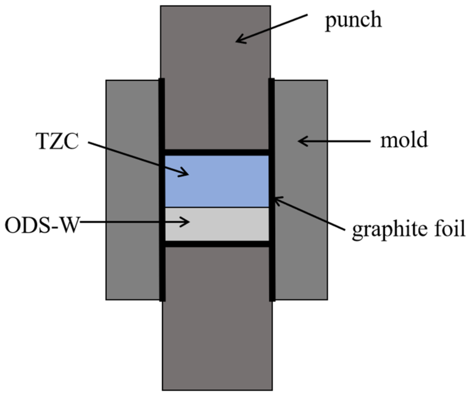
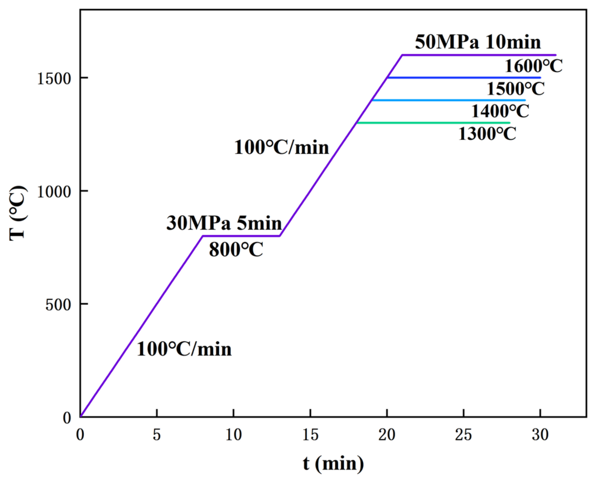
2.2. Diffusion Welding Using SPS Technique

As depicted in Figure 2, the ODS-W and TZC alloy work pieces were assembled according to a top-to-bottom stacking sequence in a graphite mold with an inner diameter of 20 mm. A graphite foil with a thickness of 0.2 mm was placed on the interior surfaces of the mold. The graphite mold was subsequently filled with alternating layers of 1 mm-thick ODS-W foil and 2 mm-thick TZC powder which were then tightly compacted using punches. Graphite foil was utilized to avoid adhesion of the specimen to both the mold and punch and facilitate its disassembly. To hinder heat dissipation, porous graphite felt of a 5 mm thickness covered the outer surface of the mold. We note that carbon atoms from the graphite layer can partially diffuse to the CoCrFeNi high-entropy alloy samples during SPS [26]. However, carbon diffusion into ODS-W/TZC joint was not observed in our SPS experiments.
Diffusion bonding is carried out under a vacuum condition with a vacuum level of 10 Pa. In the present study, the applied temperature for vacuum diffusion bonding was in the range of 1300–1600 °C. Figure 3 shows the sintering parameters for diffusion welding of the ODS-W/TZC connector, and the sintering procedure is described as follows. The sample underwent heating at a heating rate of 100 °C/min until the temperature reached 800 °C, and the temperature was maintained at 800 °C for a period of 5 min. After that, the temperature continued to increase at the same heating rate of 100 °C/min until the desired temperature was reached, and the desired temperature was maintained for an additional 10 min. Then, the specimen was cooled down to room temperature in the smelter. The starting pressure was set to 10 MPa, gradually increasing to 30 MPa when the temperature fixed at 800 °C. The pressure then further elevated to 50 MPa when the final desired temperature was maintained.

2.3. Microstructure and Performance Analysis

The microstructure of the ODS-W/TZC joints was examined using Scanning Electron Microscopy (SEM), and the diffusion of elements at the interface of the joint was analyzed using Energy Dispersive Spectroscopy (EDS). Because the thickness of the sample was several microns, we selected the Vickers hardness tester to determine the hardness of the ODS-W/TZC joint. To characterize the mechanical performance of the connector, a tensile test was conducted with the use of a universal testing machine at a loading rate of 0.1 mm/min. For the sake of precision, data for hardness and tensile strength were measured five times and carefully averaged. The fracture surface of the ODS-W/TZC joint after stretching was examined using SEM. The thermal shock resistance of the ODS-W/TZC composites fabricated at different sintering temperatures was measured by the laser beam welding machine. We first cut the ODS-W/TZC joint into 4 × 4 × 4 mm3 blocks and polished the sides of the mirror, and then performed thermal shock tests on the surface and interface of the connector. After the thermal shock tests, a confocal laser scanning microscope (CLSM) was used to analyze the morphology and damage of the joint. A CLSM is able to generate the three-dimensional structure of the sample by fast-scanning imaging technology, and the height undulation of the connector can then be easily obtained.

3. Results

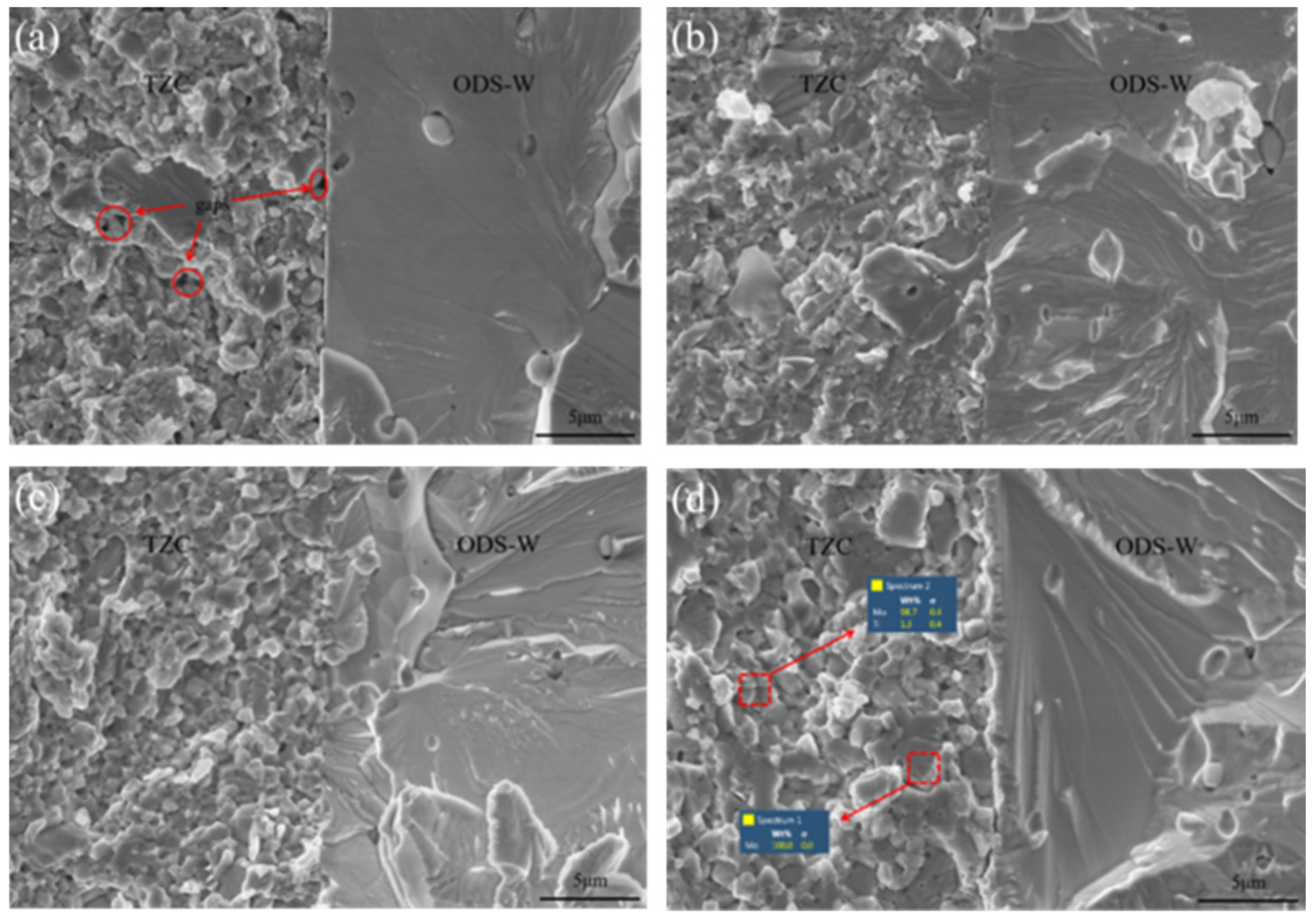
3.1. Microstructure Analysis

The microstructures of the ODS-W/TZC joint at four different sintering temperatures 1300 °C, 1400 °C, 1500 °C, and 1600 °C are displayed in Figure 4a–d, respectively. It can be seen that the interface between the ODS-W and TZC becomes increasingly blurred with the increase in sintering temperature. As shown in Figure 4a, a clear dividing interface is observed in the ODS-W/TZC joint fabricated at 1300 °C, indicating that the ODS-W and TZC materials are not tightly connected. When the sintering temperature increases to 1400 °C, the interface of the joint begins to be blurred [see Figure 4b]. As displayed in the insert maps of Figure 4a,b, some cracks appeared at the interface when the sample was sintered at 1300 °C and 1400 °C, which can be attributed to low sintered density at the two sintering temperatures. At the increased sintering temperatures of 1500 °C and 1600 °C, there was no clear dividing line at the interface of the ODS-W/TZC joint, and no obvious cracks were seen at the interface [see Figure 4c,d]. Such a scenario implies that the W and Mo atoms remarkably diffuse to each other at the interface when the temperature is higher than 1500 °C. In particular, as illustrated in Figure 4c,d, the second phase particles were evenly distributed on the TZC side at a temperature of 1500 °C or 1600 °C, and multiple second phase particles could be found at the interface. This observation indicates that the second-phase particles have a better dispersion in the ODS-W/TZC joint when the sintering temperature exceeds 1500 °C.
Figure 5a–d show the elemental distributions of W and Mo atoms at the interface of ODS-W/TZC joints fabricated at four different sintering temperatures ranging from 1300 °C to 1600 °C. It can be seen that the diffusion profile at different sintering temperatures varied continuously and smoothly, suggesting the formation of a solid solution between W and Mo atoms at the interface [27]. As seen in Figure 5a–c, the diffusion distance increased with the raising temperature between 1300 °C and 1500 °C. In particular, the diffusion distance between the W and Mo elements at 1500 °C was larger than 2 μm [see Figure 5c]. The diffusion distance was then found to decline as the sintering temperature reached 1600 °C [see Figure 5d]. This result shows that the connection of the ODS-W and TZC materials became worse at 1600 °C. The decrease of the diffusion distance above 1500 °C can be ascribed to the pronounced recrystallization of ODS-W, which typically occurs when the sintering temperature is higher than 1500 °C [8,9,10]. The recrystallization of ODS-W results in a decrease in the area of grain boundaries and thus reduces the inter-element diffusion [28]. Figure 5e,f display the W and Mo diffusion curves in Y2O3 particles at the interface of ODS-W/TZC joints at sintering temperatures of 1500 °C and 1600 °C, respectively. When Y2O3 particles are located at the interface, Mo can diffuse into Y2O3 to some extent, indicating that the Mo atoms can coexist well with the Y2O3 particles. We note that recent studies showed that the incorporation of rare earth oxides can remarkably enhance the physical and mechanical properties of Mo alloys [29,30].

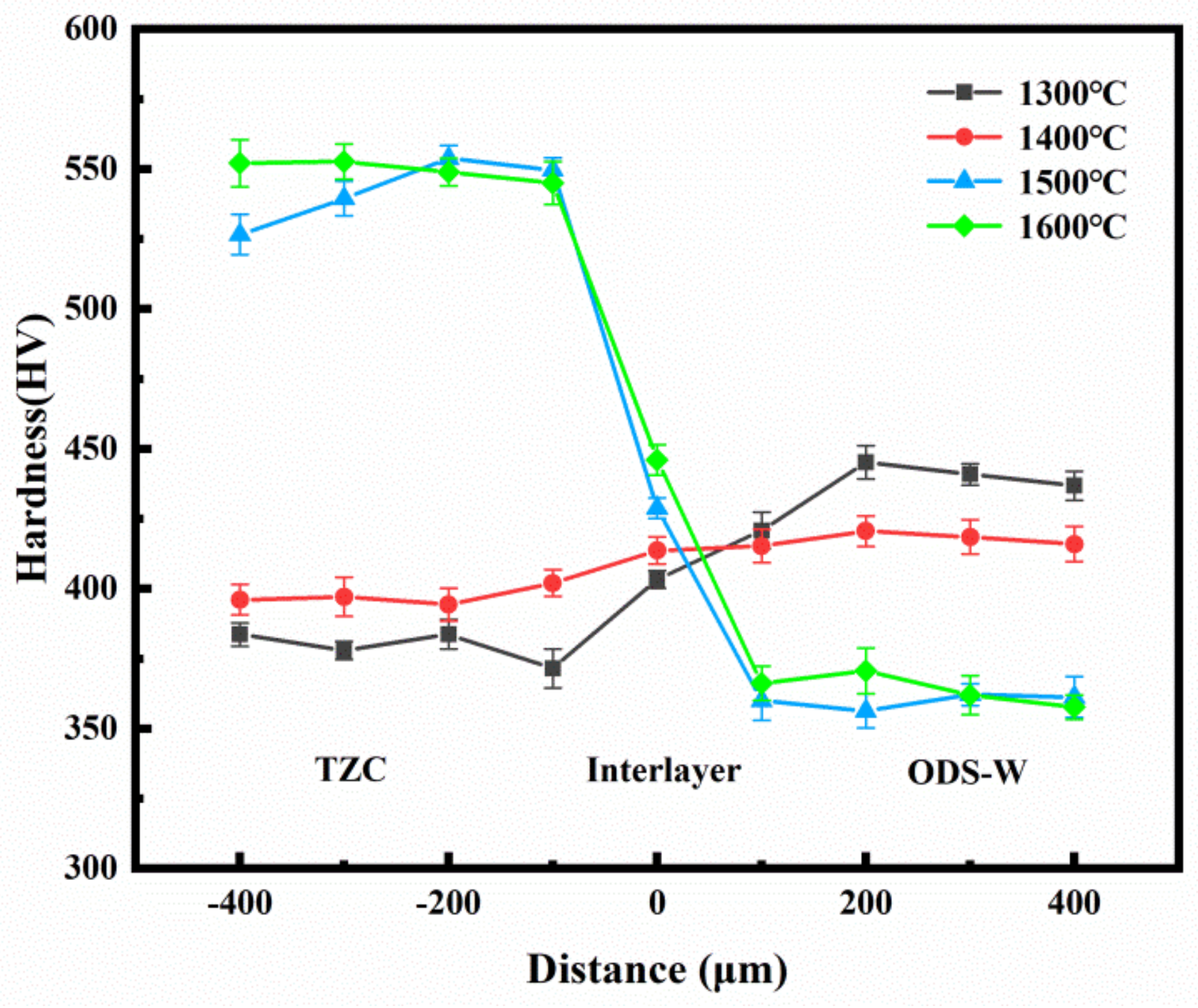
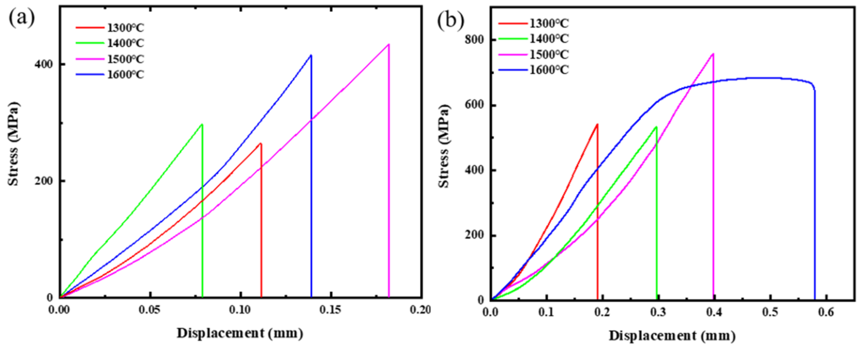
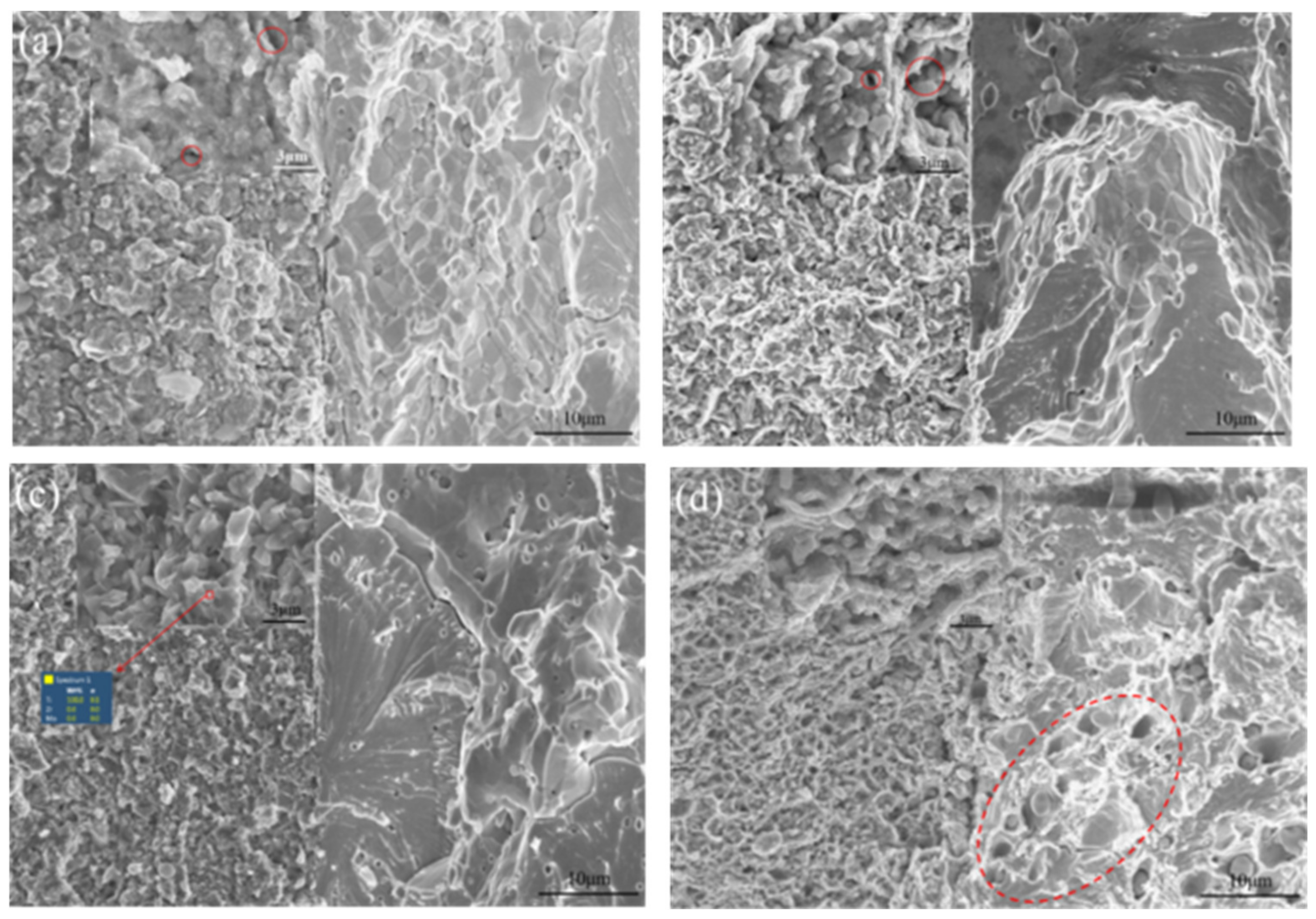
3.2. Mechanical Performance

The Vickers hardness tester was employed to evaluate the hardness of ODS-W/TZC joints fabricated at different sintering temperatures. The hardness measurements were performed in line scan mode, where the interface is taken as the origin and extends separately to 400 μm for each substrate. Each sampling point was spaced by a distance of 100 μm and a total of 9 sampling points were measured. The hardness was measured by applying a load of 300 g at each sampling point and maintaining this for a period of 10 s. Figure 6 depicts the variation of the measured hardness in the vicinity of the interface of ODS-W/TZC connectors at various sintering temperatures. It can be seen from Figure 6 that the raise in sintering temperature lead to an increase in the hardness of the TZC substrate. The increased hardness of the TZC substrate may be due to the enhanced degree of densification of the TZC substrate at higher temperature, shown in Figure 4 above. In particular, the hardness of the ODS-W substrate side decreased significantly when the sintering temperature was above 1500 °C. This is because that the recrystallization temperature of ODS-W is about 1500 °C [8,9,10], and the occurrence of recrystallization can significantly reduce the strength and hardness of the ODS-W. In addition, it was found that the hardness value at the interface of joint was between the hardness values of the two substrates when the sintering temperature was above 1500 °C. Such a scenario can be explained as follows. On the one hand, since the W and Mo atoms are miscible, diffusing to form a solid solution rather than the metallic alloys at the interface; thus, the hardness will not remarkably increase [31,32]. On the other hand, the thickness of the diffusion layer at the interface is about 2 μm, and the measurement of hardness through Vickers indentation at the interface is influenced by both substrates [33]. When sintered at 1600 °C, a maximum hardness of 446 HV is achieved at the interface of the ODS-W/TZC connector.
Considering that the thickness of the SPS sintered specimen was limited, here, the tensile direction of the ODS-W/TZC joint was in a direction parallel to the interface of the ODS-W/TZC joint. The tensile properties of the joints were measured via a universal testing machine at both an ambient temperature and elevated temperature of 500 °C. Figure 7a,b display the stress–displacement curves of the ODS-W/TZC joint at room temperature and 500 °C, respectively. It is shown that the tensile strengths of the samples sintered at 1300 °C and 1400 °C are relatively lower, which can be ascribed to the poor densification of TZC substrate after sintering [see Figure 4a,b]. Among all the tensile data at different sintering temperatures, it is observed that the ODS-W/TZC connector bonded at 1500 °C exhibited the best tensile performance both at room temperature and elevated temperatures, with a tensile strength of 459 MPa at room temperature and 786 MPa at a temperature of 500 °C. This is because ODS-W and TZC materials have the best connection effect at temperature of 1500 °C, as shown in Figure 4c. As can be inferred from the previous analysis, recrystallization of the ODS-W occurs at a temperature of about 1500 °C [8,9,10], which weakens the tensile performance of the joint. Therefore, the tensile strength of the ODS-W/TZC connector sintered at 1600 °C slightly decreased compared to that sintered at 1500 °C.
By comparing the tensile strengths of the ODS-W/TZC joint at the two different temperatures, it can be seen that the tensile strength of all samples at 500 °C is much higher than the counterpart at room temperature. This scenario contradicts the typical inherent trade-off between the strength and plasticity of metals [34,35], and may be related to the doping of CNTs in TZC alloy. The TZC alloy considered in this study adopts CNTs as a carbon source. The doping of CNTs at high temperatures can increase the short-range order of the joint and refine the grain structure so that the tensile strength of the ODS-W/TZC joint at a high temperature can be enhanced through the synergistic cooperation of CNTs and the metallic matrix.
The fracture morphologies of the ODS-W/TZC joints sintered at 1300 °C, 1400 °C, 1500 °C, and 1600 °C under tension at room temperature are displayed in Figure 8a–d, respectively. It was observed that the fracture morphology on the TZC side was significantly different from that on the ODS-W side. As depicted in Figure 8a, there existed numerous holes on the fracture surface of TZC side at 1300 °C. This result indicates that the densification of TZC side is lower when sintered at 1300 °C, which agrees well with the microstructure presented in Figure 4a. In addition, a clear dividing line was observed at the interface [see Figure 8a], indicating that the ODS-W and TZC materials were not tightly connected. At a sintering temperature of 1400 °C, the number of holes on the TZC side decreased significantly and an effective connection was formed between the ODS-W and TZC materials [see Figure 8b]. When the ODS-W/TZC joint was sintered at 1500 °C, there were no obvious holes on the TZC side and the fracture morphology on the TZC side mainly comprised intergranular fractures [see Figure 8c]. Meanwhile, the grain size on the TZC side was very refined at 1500 °C [see Figure 8c], which can also explain the best tensile performance of ODS-W/TZC joint at this temperature [see Figure 7]. At a sintering temperature of 1600 °C, the TZC side exhibited a mixed fracture mode of transgranular and intergranular fractures. The insert map in Figure 8d shows the elemental composition of intergranular and transgranular cracks. Pure Mo is detected in the transgranular crack, while pure Ti is found in the intergranular crack, which suggests that the doping of carbides is capable of enhancing grain boundary cohesion and hence improves the material strength. As seen in Figure 8a–d, the fracture morphologies on the ODS-W side are primarily the cleavage fracture at all sintering temperatures.
Figure 9a–d show the fracture morphologies of the ODS-W/TZC joints sintered under tension at temperatures of 500 °C at 1300 °C, 1400 °C, 1500 °C, and 1600 °C, respectively. As seen in Figure 9a, at 1300 °C the densification of the TZC side was poor and the TZC side seemed like an agglomeration of the powder, and the fracture mode on the TZC side was not the intergranular fracture. At a sintering temperature of 1400 °C there were still a large number of holes on the TZC side, and the densification of TZC side was still lower [see Figure 9b]. When the sample was sintered at 1500 °C, it is observed that the fracture mode on the TZC side was mainly intergranular fracture, and many long strip-shaped grains appeared on the fracture surface [see Figure 9c]. For the sintering temperature of 1600 °C, a network-like grain structure was observed on the fracture surface of the TZC side [36] and the grains were well refined. In addition, by conducting a comparative analysis between the tensile fracture behaviors of TZC material at room temperature and 500 °C, it can be observed that the size of grains in the TZC reduced significantly when temperature increased from room temperature to 500 °C. The reduction in grain size at higher temperature can be attributed to the doping of CNTs, which can increase the short-range order of the joint and refine the grain structure, and thus lead to a higher tensile strength [37]. Compared to the room temperature case, the ODS-W side had a diverse fracture mode. In addition to the cleavage fracture, intercrystalline fracture was also observed on the ODS-W side. In particular, several craters were observed on the fracture surface of the ODS-W side [see Figure 9d], which can be attributed to the recrystallization of ODS-W.

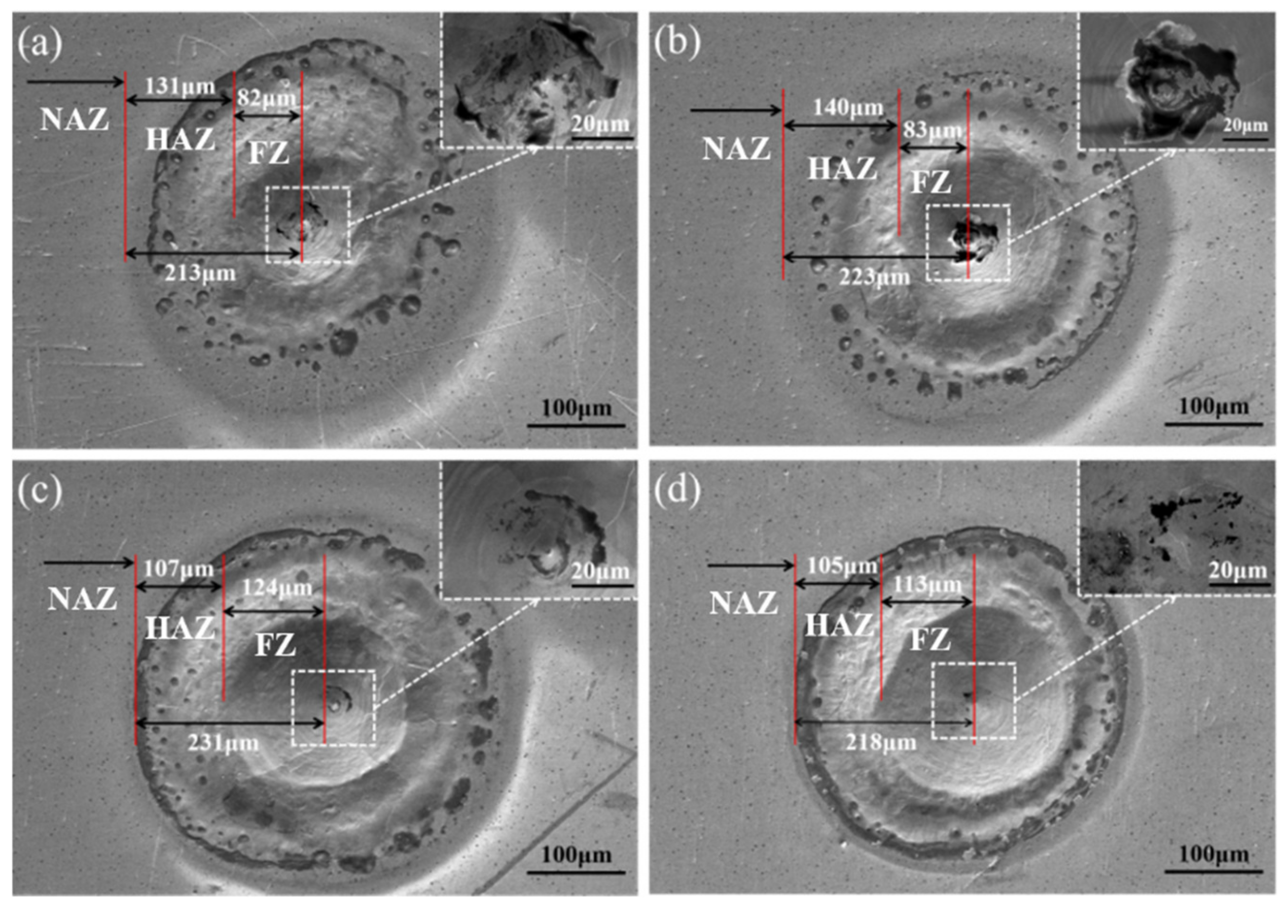
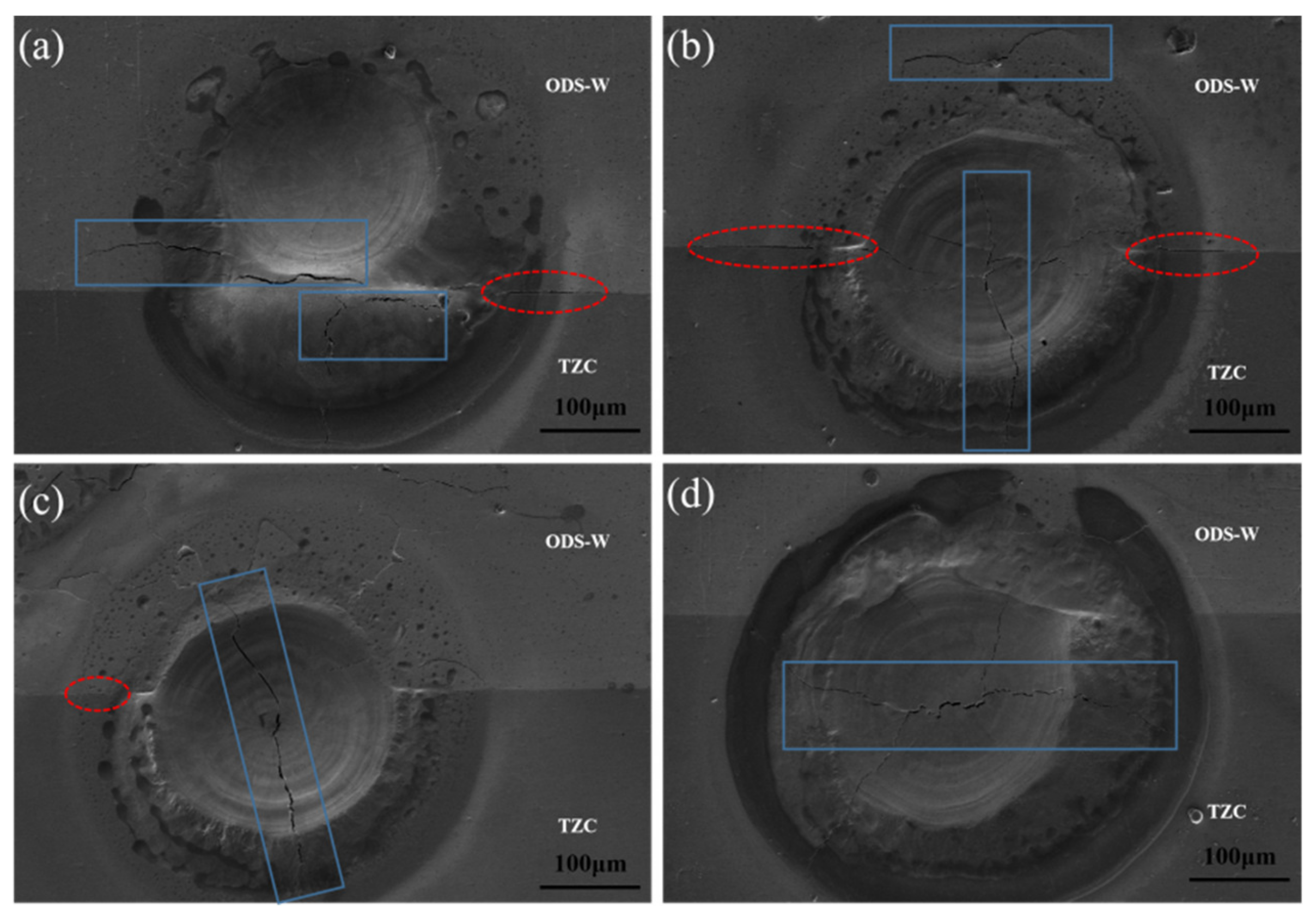
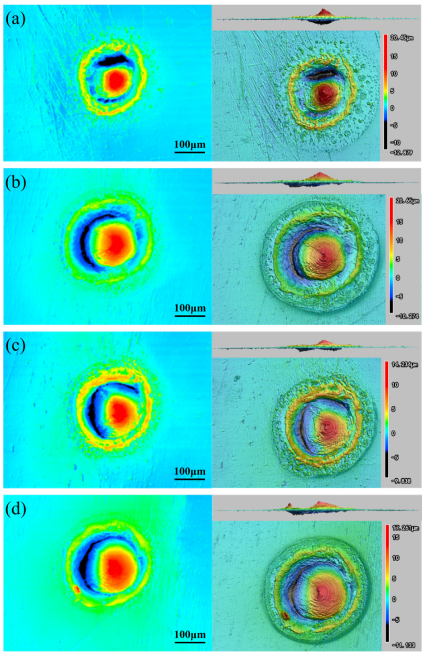
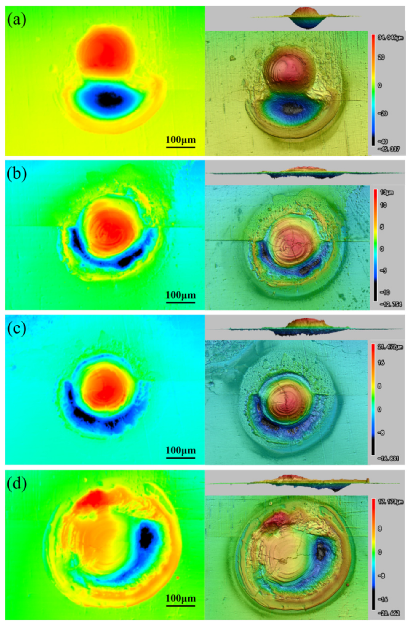
3.3. Damage of ODS-W/TZC Subjected to Transient Laser Thermal Load

Figure 10 illustrates the surface morphology of the ODS-W/TZC joint subjected to a transient laser heat load. The panels (a)–(d) in Figure 10 correspond to the samples fabricated at temperatures of 1300 °C, 1400 °C, 1500 °C and 1600 °C, respectively. After thermal shock, the surface can be mainly classified into three regions from the center to the outward edge of the ODS-W/TZC joint, i.e., the fusion zone (FZ), heat affected zone (HAZ), and unaffected zone (NAZ) [38]. As seen in Figure 10a,b, there was no obvious difference between the damaged areas of the ODS-W/TZC joints prepared at 1300 °C and 1400 °C. For instance, both the FZ diameters of the joints fabricated at 1300 °C and 1400 °C were around 80 μm, and their HAZ diameters were in the range of 130–140 μm. In addition, there was also no obvious difference between the damaged areas of the ODS-W/TZC joint prepared at 1500 °C and 1600 °C, as shown in Figure 10c,d. Comparing the damaged areas of the ODS-W/TZC joints fabricated at different temperatures, it can be found that the FZ diameter of the connectors at the higher temperatures of 1500 °C and 1600 °C (about 120 μm) was much larger than those at the lower temperatures of 1300 °C and 1400 °C (about 80 μm). However, the HAZ diameter of the connectors fabricated at the higher temperatures of 1500 °C and 1600 °C was obviously smaller than those at the lower temperatures of 1300 °C and 1400 °C. When comparing the surface damage of the ODS-W subjected to transient laser heat loading [39] with that of the connector, it can be observed that the diameter of the damaged region in the connector was larger. However, unlike the ODS-W sample [39], no cracks were detected in the damaged region of the connector.
The interface morphologies of the ODS-W/TZC joints under a transient laser heat load, which are fabricated at 1300 °C, 1400 °C, 1500 °C, and 1600 °C, are displayed in Figure 11a–d, respectively. Since a set of experimental laser points act at the interface of the joint, the damaged zone is composed of injured sites of two substrates. Figure 11a shows the damaged interface of the sample sintered at the temperature of 1300 °C. It is observed that there was no obvious damage on the ODS-W side, while significant melting occurred on the TZC side. In addition, several irregularly oriented cracks appeared at the interface of the joint and an exfoliation phenomenon was observed. When the sintering temperature was 1400 °C, the melting of TZC was reduced but numerous cracks were still observed at the interface [see Figure 11b]. At a sintering temperature of 1500 °C, the degree of the damage was remarkably decreased, and no ablation occurred in the damage area, as illustrated in Figure 9c. There was no obvious defect at the interface except for a penetrating crack produced at the center. When the sample was sintered at 1600 °C, only a few cracks appeared on the TZC side [see Figure 9d], and the damage of the interface was tiny.
Figure 12a–d display the 3D altitude diagrams of the surfaces of the ODS-W/TZC joints fabricated at sintering temperatures of 1300 °C, 1400 °C, 1500 °C, and 1600 °C after transient laser heat load. The upper and lower limits of the measurement scale in each panel correspond to the largest and smallest difference values of the damage area relative to the height of the initial surface. As depicted in the Figure 12, the height undulation ranges of the surfaces of the ODS-W/TZC connectors sintered at 1300 °C, 1400 °C, 1500 °C, and 1600 °C were [−12.879, 20.45], [−10.274, 20.65], [−9.838, 14.234], and [−11.133, 17.261], respectively. It can be found that the height fluctuation of the surface was gradually reduced with increasing temperature at 1300–1500 °C, but then slightly increased when the temperature further increased to 1600 °C. Such a result shows that the ODS-W/TZC connectors exhibits the best thermal shock resistance when fabricated at a sintering temperature of 1500 °C. In addition, the 3D height diagrams of the ODS-W/TZC connectors and the ODS-W were compared when they were both subjected to transient laser heat load. It can be inferred from a recent experimental study [39] that the surface of ODS-W sintered at 1500 °C has a height undulation interval of [−14.793, 23.746], which is larger than that of the ODS-W/TZC connector. This result indicates that the ODS-W/TZC connector possesses a better thermal shock resistance than the ODS-W.
The 3D altitude diagrams in Figure 13a–d illustrate the interface morphologies of the ODS-W/TZC connectors prepared at 1300 °C, 1400 °C, 1500 °C, and 1600 °C after being subjected to a transient laser heat load. Because the transient laser thermal load is applied at the interface of the ODS-W/TZC connector, the damage of the interface is much worse than that of the surface. It can be intuitively seen in Figure 13a that the damage of the sintered specimen at 1300 °C is significant. The undulation interval of the interface is [−45.337, 34.046], and the height fluctuation is much higher than that of other samples prepared at different temperatures. For the sintering of 1500 °C, the interface has a minimal undulation interval of [−16.831, 21.472], and indicates again that the ODS-W/TZC connectors fabricated at a sintering temperature of 1500 °C exhibit the best thermal shock resistance.

4. Conclusions

The diffusion welded joint of ODS-W and TZC is successfully achieved via the SPS technique. Based on the analysis of microscopic morphology and mechanical performance, the following conclusions are drawn:
(1)
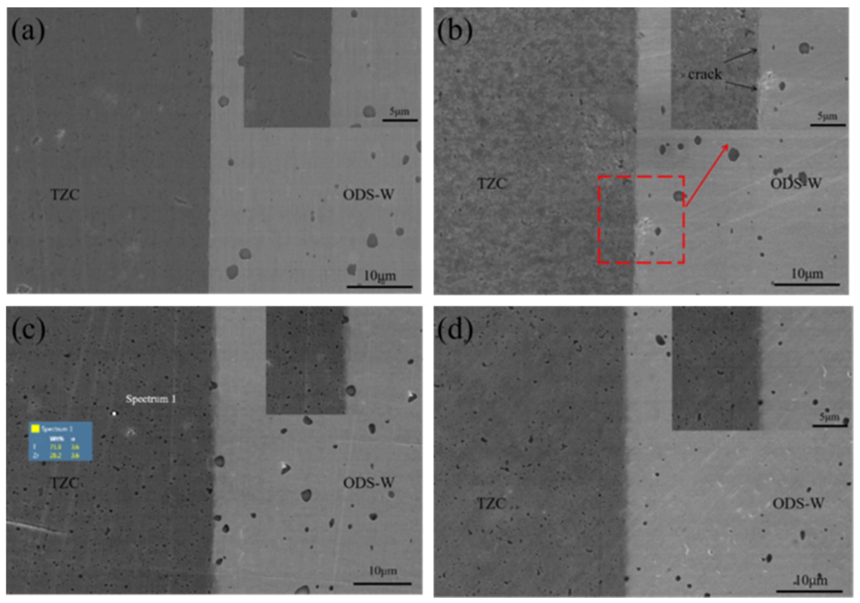
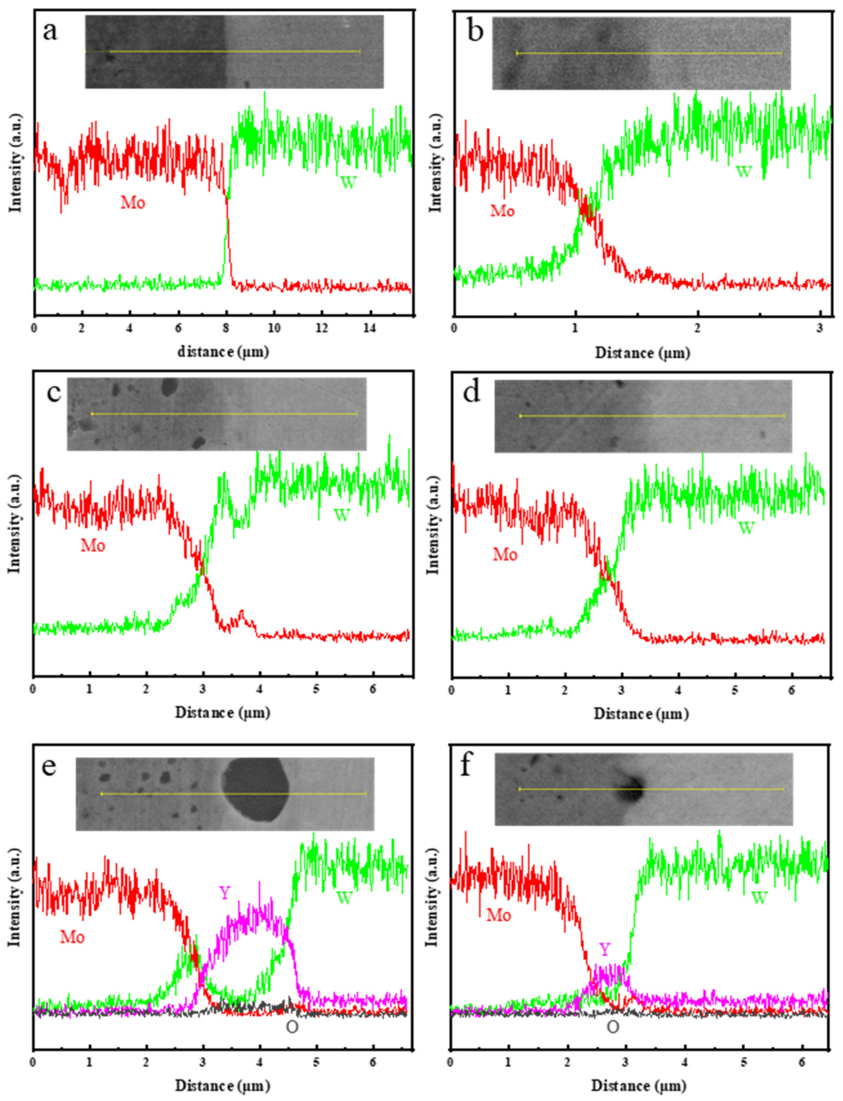
When the sintering temperature is above 1500 °C, TZC will begin to densify, and there is no obvious defect at the interface. As the sintering temperature increases, diffusion of W and Mo atoms at the joint interface becomes more extensive, with a diffusion distance of up to 2 μm observed at 1500 °C. However, sintering at 1600 °C leads to grain growth caused by recrystallization of ODS-W and decreases the diffusion distance because of the reduced area of grain boundaries. In addition, the presence of Y2O3 second phase particles at the interface will promote the interdiffusion between W and Mo atoms.
(2)
The tensile strength of the ODS-W/TZC connector exhibits an initial enhancement followed by a slight reduction with increasing sintering temperatures. Specifically, the maximum tensile strength is achieved at sintering temperature of 1500 °C, with values of 459 MPa and 786 MPa obtained at room temperature and 500 °C, respectively.
(3)
The ODS-W/TZC connector exhibits an optimal thermal shock resistance when sintered at 1500 °C, as indicated by the comprehensive results of the performed thermal shock tests. Analysis utilizing CLSM demonstrates that the surface and interface of the ODS-W/TZC connector exhibit a markedly reduced height undulation compared to that of the ODS-W sample, providing evidence for its superior thermal shock resistance.

Author Contributions

Conceptualization: D.L. and X.L.; Data curation: S.Z., D.L. and X.L.; Funding acquisition: D.L., X.L. and C.H.; Methodology: S.Z. and Z.L.; Resources: D.L. and X.L.; Supervision, D.L. and X.L.; Visualization, J.Z., C.R. and L.M.; Writing—original draft, S.Z., J.Z., C.R. and L.M.; Writing-review and editing: D.L., X.L. and C.H. All authors have read and agreed to the published version of the manuscript.

Funding

This work was funded by the National Natural Science Foundation of China (U22A20110 and 12272118), Anhui Natural Science Foundation (2008085ME128), Major Science and technology projects of Anhui Province (202103a05020003), and Open Fund Project of Fujian Provincial Key Laboratory of Advanced Materials Processing and Application (E4700014).

Data Availability Statement

The data generated and/or analyzed during the current study are not publicly available for legal/ethical reasons but are available from the corresponding author on reasonable request.

Conflicts of Interest

The authors declare no conflict of interest.

References

  1. Kaserer, L.; Braun, J.; Stajkovic, J.; Leitz, K.H.; Singer, P.; Letofsky-Papst, I.; Kestler, H.; Leichtfried, G. Molybdenum alloy Mo-Ti-Zr-C adapted for laser powder bed fusion with refined isotropic microstructure and excellent high temperature strength. Int. J. Refract. Met. Hard Mater. 2023, 113, 106174. [Google Scholar] [CrossRef]
  2. Tian, G.; Xu, L.; Fang, H.; Li, Z.; Li, X.; Zhou, Y.; Wei, S. Deformation behavior and microstructure evolution of TZM alloy with 1.0wt%ZrO2 under high temperature compression. Int. J. Refract. Met. Hard Mater. 2023, 117, 106382. [Google Scholar] [CrossRef]
  3. Meng, X.C.; Li, L.; Li, C.L.; Andruczyk, D.; Tritz, K.; Maingi, R.; Huang, M.; Zhang, D.H.; Xu, W.; Sun, Z.; et al. Corrosion characteristics of Mo and TZM alloy for plasma facing components in molten lithium at 623 K. Corros. Sci. 2022, 200, 110202. [Google Scholar] [CrossRef]
  4. Chakraborty, S.P.; Banerjee, S.; Singh, K.; Sharma, I.G.; Grover, A.K.; Suri, A.K. Studies on the development of protective coating on TZM alloy and its subsequent characterization. J. Mater. Process. Technol. 2008, 207, 240–247. [Google Scholar] [CrossRef]
  5. Yavas, B.; Goller, G. Functional design to protect TZM alloy against oxidation. Oxid. Met. 2021, 95, 389–407. [Google Scholar] [CrossRef]
  6. Gaganidze, E.; Chauhan, A.; Schneider, H.C.; Terentyev, D.; Borghmans, G.; Aktaa, J. Fracture-mechanical properties of neutron irradiated ITER specification tungsten. J. Nucl. Mater. 2021, 547, 152761. [Google Scholar] [CrossRef]
  7. Wu, M.; Wang, Z.; Zhang, N.; Ge, C.; Zhang, Y. Theoretical predictions of the structural and mechanical properties of tungsten–rare earth element alloys. Materials 2021, 14, 3046. [Google Scholar] [CrossRef] [PubMed]
  8. Hu, W.Q.; Yu, L.M.; Ma, Z.Q.; Liu, Y.C. W-Y2O3 composite nanopowders prepared by freeze-drying method and its sintering characteristics. J. Alloys Compd. 2019, 806, 127–135. [Google Scholar] [CrossRef]
  9. Li, L.; Dong, Z.; Ma, Z.; Liu, C.; Yu, L.; Liu, Y. Ultrahigh strength and toughness in W-Y2O3 alloy with bimodal and lamellar structures. Mater. Res. Lett. 2023, 11, 439–445. [Google Scholar]
  10. Wei, M.; Feng, F.; Wang, J.; Qiang, J.; Shi, Y.; Hao, S.; Liu, X.; Wang, Y.; Lian, Y. Room temperature ductile W-Y2O3 alloy with high thermal shock resistance. Int. J. Refract. Met. Hard Mater. 2023, 114, 106261. [Google Scholar] [CrossRef]
  11. Mastikhin, E.Y.; Bashurin, A.V.; Kolmykov, V.I. Diffusion welding of structures made of titanium and aluminium alloys using the superplasticity effect. Weld. Int. 2015, 29, 985–987. [Google Scholar] [CrossRef]
  12. Liu, W.S.; Pang, X.K.; Cai, Q.S.; Ma, Y.Z.; Zhu, W.T. Fabrication of W/steel joint using hot isostatic pressing with Ti/Cu/Ti liquid forming interlayer. Fusion Eng. Des. 2018, 135, 59–64. [Google Scholar] [CrossRef]
  13. Liu, D.G.; Meng, L.; Zou, J.X.; Luo, L.M.; Wu, Y.C. Microstructure and properties of silver-added W-Cu prepared by infiltration sintering. Int. J. Refract. Met. Hard Mater. 2022, 108, 105947. [Google Scholar] [CrossRef]
  14. Song, X.G.; Han, G.H.; Hu, S.P.; Zhao, H.Y.; Li, Y.; Wang, M.R.; Shi, B. Evaluation of TZM/ZrCp-W joint brazed with Ti-35Ni fifiller: Microstructure and mechanical properties. Mater. Sci. Eng. A 2019, 742, 190–200. [Google Scholar] [CrossRef]
  15. Han, G.H.; Bian, H.; Zhao, H.Y.; Song, X.G.; Li, Y.; Liu, D.; Cao, J.; Feng, J.C. Interfacial microstructure and mechanical properties of TZM alloy and ZrC particle reinforced tungsten composite joint brazed using Ti-61Ni Fifiller. J. Alloys Compd. 2018, 747, 266–275. [Google Scholar] [CrossRef]
  16. Abedi, M.; Sovizi, S.; Azarniya, A.; Giuntini, D.; Seraji, M.E.; Hosseini, H.R.M.; Amutha, C.; Ramakrishna, S.; Mukasyan, A. An analytical review on Spark Plasma Sintering of metals and alloys: From processing window, phase transformation, and property perspective. Crit. Rev. Solid State Mater. Sci. 2023, 48, 169–214. [Google Scholar] [CrossRef]
  17. Ananthakumar, K.; Vivekanandhan, P.; Kumaran, S. Spark plasma assisted diffusion bonding of titanium and stainless steel: Role of pulse current in diffusion kinetics and microstructural evolution. Vacuum 2020, 177, 109394. [Google Scholar] [CrossRef]
  18. Leszczyńska-Madej, B.; Garbiec, D.; Madej, M. Effect of sintering temperature on microstructure and selected properties of spark plasma sintered Al-SiC composites. Vacuum 2019, 164, 250–255. [Google Scholar] [CrossRef]
  19. Frelek-Kozak, M.; Kurpaska, L.; Wyszkowska, E.; Jagielski, J.; Jozwik, I.; Chmielewski, M. Evaluation of consolidation method on mechanical and structural properties of ODS RAF steel. Appl. Surf. Sci. 2018, 446, 215–221. [Google Scholar] [CrossRef]
  20. Chmielewski, M.; Nosewicz, S.; Wyszkowska, E.; Kurpaska, Ł.; Strojny-Nędza, A.; Piątkowska, A.; Bazarnik, P.; Pietrzak, K. Analysis of the micromechanical properties of copper-silicon carbide composites using nanoindentation measurements. Ceram. Int. 2019, 45, 9164–9173. [Google Scholar] [CrossRef]
  21. Moazzen, P.; Toroghinejad, M.R.; Zargar, T.; Cavaliere, P. Investigation of hardness, wear and magnetic properties of NiCoCrFeZrx HEA prepared through mechanical alloying and spark plasma sintering. J. Alloys Compd. 2021, 892, 161924. [Google Scholar] [CrossRef]
  22. Yang, Z.; Hu, K.; Hu, D.W.; Han, C.L.; Tong, Y.G.; Yang, X.Y.; Wei, F.Z.; Zhang, J.X.; Shen, Y.; Chen, J.; et al. Diffusion bonding between TZM alloy and WRe alloy by spark plasma sintering. J. Alloys Compd. 2018, 764, 582–590. [Google Scholar] [CrossRef]
  23. Liu, D.G.; Ma, H.R.; Ruan, C.F.; Luo, L.M.; Zan, X.; Wang, Z.M.; Wu, Y.C. Effective joining between oxide dispersion strengthened tungsten-based material (ODS-W) and TZM alloy via spark plasma sintering technology. Results Mater. 2021, 9, 100175. [Google Scholar] [CrossRef]
  24. Husam, A.S.; Abdullah, M.J. Preparation of ZnO nanostructures by RF-magnetron sputtering on thermally oxidized porous silicon substrate for VOC sensing application. Measurement 2015, 59, 248–257. [Google Scholar]
  25. Jiang, D.F.; Long, J.Y.; Cai, M.Y.; Lin, Y.; Fan, P.X.; Zhang, H.J.; Zhong, M.L. Femtosecond laser fabricated micro/nano interface structures toward enhanced bonding strength and heat transfer capability of W/Cu joining. Mater. Des. 2017, 114, 185–193. [Google Scholar] [CrossRef]
  26. Olejarz, A.; Huo, W.Y.; Zieliński, M.; Diduszko, R.; Wyszkowska, E.; Kosińska, A.; Kalita, D.; Jóźwik, I.; Chmielewski, M.; Fang, F.; et al. Microstructure and mechanical properties of mechanically-alloyed CoCrFeNi high-entropy alloys using low ball-to-powder ratio. J. Alloys Compd. 2023, 938, 168196. [Google Scholar] [CrossRef]
  27. Liu, Y.J.; Long, Z.H.; Du, Y.; Sheng, G.; Wang, J.; Zhang, L.J. Diffusion characteristics and atomic mobilities for bcc refractory Mo-Ta, Mo-W, and Mo-Nb alloys. Calphad 2012, 36, 110–117. [Google Scholar] [CrossRef]
  28. Zan, X.Q.; Wang, D.Z.; Shi, K.H.; Sun, A.K.; Xu, B. Effect of MoSi2/rare earth composite particles on microstructure and mechanical properties of molybdenum. Int. J. Refract. Met. Hard Mater. 2011, 29, 505–508. [Google Scholar] [CrossRef]
  29. Liu, R.Z.; Wang, K.S.; Feng, P.F.; An, G.; Yang, Q.L.; Zhao, H. Microstructure and tensile properties of Mo alloy synthetically strengthened by nano-Y2O3 and nano-CeO2. Rare Met. 2014, 33, 58–64. [Google Scholar] [CrossRef]
  30. Yao, L.Y.; Wei, S.Z.; Zhou, Y.C.; Xu, L.J.; Chen, C.; Sun, T.L.; Shi, P.P. Preparation and characterization of Mo/ZrO2-Y2O3 composites. Int. J. Refract. Met. Hard Mater. 2018, 75, 202–210. [Google Scholar] [CrossRef]
  31. Tuzemen, C.; Yavas, B.; Akin, I.; Yucel, O.; Sahin, F.; Goller, G. Production and characterization of TZM based TiC or ZrC reinforced composites prepared by spark plasma sintering (SPS). J. Alloys Compd. 2019, 781, 433–439. [Google Scholar] [CrossRef]
  32. Ohser-Wiedemann, R.; Weck, C.; Martin, U.; Müller, A.; Seifert, H.J. Spark plasma sintering of TiC particlereinforced molybdenum composites. J. Alloys Compd. 2012, 32, 1–6. [Google Scholar]
  33. Danisman, C.B.; Yavas, B.; Yucel, O.; Sahin, F.; Goller, G. Processing and characterization of spark plasma sintered TZM alloy. J. Alloys Compd. 2016, 685, 860–868. [Google Scholar] [CrossRef]
  34. Chen, B.; Li, S.F.; Imai, H.; Jia, L.; Umeda, J.; Takahashi, M.; Kondoh, K. Load transfer strengthening in carbon nanotubes reinforced metal matrix composites via in-situ tensile tests. Compos. Sci. Technol. 2015, 113, 1–8. [Google Scholar] [CrossRef]
  35. Chen, B.; Shen, J.; Ye, X.; Jia, L.; Li, S.; Umeda, J.; Takahashi, M.; Kondoh, K. Length effect of carbon nanotubes on the strengthening mechanisms in metal matrix composites. Acta Mater. 2017, 140, 317–325. [Google Scholar] [CrossRef]
  36. Browning, P.N.; Fignar, J.; Kulkarni, A.; Singh, J. Sintering behavior and mechanical properties of Mo-TZM alloyed with nanotitanium carbide. Int. J. Refract. Met. Hard Mater. 2017, 62, 78–84. [Google Scholar] [CrossRef]
  37. Wei, Y.; Luo, L.M.; Liu, H.B.; Zan, X.; Song, J.P.; Xu, Q.; Zhu, X.Y.; Wu, Y.C. A powder metallurgy route to fabricate CNT-reinforced molybdenum-hafnium-carbon composites. Mater. Design 2020, 191, 108635. [Google Scholar] [CrossRef]
  38. Linke, C.J.; Du, J.; Loewenhoff, T.; Pintsuk, G.; Spilker, B.; Steudel, I. Challenges for plasmafacing components in nuclear fusion. Matter Radiat. Extrem. 2019, 4, 75–92. [Google Scholar] [CrossRef]
  39. Liu, D.G.; Meng, L.; Ruan, C.F.; Luo, L.M.; Wu, Y.C. Interfacial microstructure and thermal shock resistance of diffusion bonding ODS-W and molybdenum alloy by spark plasma sintering. Int. J. Refract. Met. Hard Mater. 2022, 107, 105913. [Google Scholar] [CrossRef]
Figure 1. SEM image of the TZC powder after ball milling.
Metals 13 01802 g001
Figure 2. Schematic diagram of component assembly of diffusion bonding using the SPS technique.
Metals 13 01802 g002
Figure 3. The parameters for SPS-assisted diffusion welding of ODS-W and TZC alloys.
Metals 13 01802 g003
Figure 4. SEM images of the ODS-W/TZC connectors bonded at four different temperatures: (a) 1300 °C, (b) 1400 °C, (c) 1500 °C, and (d) 1600 °C. The red square in Figure 4b shows that some cracks appeared at the interface.
Metals 13 01802 g004
Figure 5. (ad) Elemental distribution curves (Mo and W) across the ODS-W/TZC interface which was bonded at four different temperatures: (a) 1300 °C, (b) 1400 °C, (c) 1500 °C, and (d) 1600 °C. (e,f) Elemental distribution curves (Mo, W, Y, O) in the Y2O3 particles at the interface of ODS-W/TZC joints at sintering temperatures of (e) 1500 °C and (f) 1600 °C.
Metals 13 01802 g005
Figure 6. Measured values of hardness of ODS-W/TZC connectors at various sintering temperatures.
Metals 13 01802 g006
Figure 7. Stress–displacement curves of ODS-W/TZC joints bonded at different temperatures under tensile loading at (a) room temperature, and (b) 500 °C.
Metals 13 01802 g007
Figure 8. Fracture morphologies of the ODS-W/TZC joints prepared at four different sintering temperatures: (a) 1300 °C, (b) 1400 °C, (c) 1500 °C, and (d) 1600 °C under tension at room temperature.
Metals 13 01802 g008
Figure 9. Fracture morphologies of the ODS-W/TZC joints prepared at four different sintering temperatures: (a) 1300 °C, (b) 1400 °C, (c) 1500 °C, (d) 1600 °C under tension at a temperature of 500 °C.
Metals 13 01802 g009
Figure 10. The surface morphologies of ODS-W/TZC joints fabricated at four different sintering temperatures after transient laser thermal load: (a) 1300 °C; (b) 1400 °C; (c) 1500 °C; (d) 1600 °C.
Metals 13 01802 g010
Figure 11. The interface morphologies of ODS-W/TZC joints fabricated after transient laser thermal load at the following four different sintering temperatures: (a) 1300 °C; (b) 1400 °C; (c) 1500 °C; (d) 1600 °C.
Metals 13 01802 g011
Figure 12. The 3D height diagrams of the surface of the ODS-W/TZC joint fabricated after transient laser thermal load at the following four different sintering temperatures: (a) 1300 °C; (b) 1400 °C; (c) 1500 °C; (d) 1600 °C.
Metals 13 01802 g012
Figure 13. The 3D height diagrams of the interface of the ODS-W/TZC joints fabricated after transient laser thermal load at the following four different sintering temperatures: (a) 1300 °C; (b) 1400 °C; (c) 1500 °C; (d) 1600 °C.
Metals 13 01802 g013
Table 1. Chemical composition of TZC and ODS-W in wt.%.
MaterialElement
WY2O3TiZrCNTMo
ODS-WBal0.53
TZC 1.50.30.4Bal
Disclaimer/Publisher’s Note: The statements, opinions and data contained in all publications are solely those of the individual author(s) and contributor(s) and not of MDPI and/or the editor(s). MDPI and/or the editor(s) disclaim responsibility for any injury to people or property resulting from any ideas, methods, instructions or products referred to in the content.

