Article

Hot Work Mold Repaired via Hot Isostatic Pressing towards High Red Hardness

1
Department of Mechanical Engineering, Tsinghua University, Beijing 100084, China
2
China Machinery Institute of Advanced Materials Co., Ltd., Zhengzhou 450001, China
*
Author to whom correspondence should be addressed.
Metals 2023, 13(10), 1783; https://doi.org/10.3390/met13101783
Submission received: 26 September 2023 / Revised: 17 October 2023 / Accepted: 18 October 2023 / Published: 20 October 2023
(This article belongs to the Section Powder Metallurgy)

Abstract

:
Repairing hot work molds can extend their lifespans and reduce the production costs. This study presents a proposed method for enhancing the red hardness and strength of repaired molds. The method involves utilizing PM23 high-speed steel powder to repair H13 steel molds with two distinct surface states through the process of hot isostatic pressing (HIP). The internal microstructure changes, bonding state, fracture morphology, and crack extension behaviors of the repaired molds are characterized using scanning electron microscopy and electron backscatter diffraction technology. Additionally, the mechanical properties, including red hardness and tensile strength, are quantitatively analyzed. The findings indicate that the repaired area in the sandblasted sample exhibits a rough and uneven structure, demonstrating exceptional toughness. The tensile strength of the repaired region is approximately 1195.42 MPa, while the hardness measures around 672.8 HV. These properties effectively enhance the performance of the molds. The experimental findings indicate that HIP can effectively restore molds, resulting in enhanced red hardness and improved toughness, particularly when combined with sandblasting as a pretreatment method.

1. Introduction

The automobile, electronics, aerospace, energy, defense, and other diverse industries all rely on hot work molds [1,2,3,4]. Hot work molds are susceptible to wear, corrosion, and fatigue cracking as a result of their highly complex processing, lengthy production cycles, and high costs [5,6,7]. Businesses will suffer significant financial losses and contribute significantly to industrial resource waste if the failed molds are immediately thrown away. As a result, repairing hot work molds is important. In addition to prolonging their lifespans and minimizing the production costs, failed molds might be repaired to increase the efficiency of the mold materials’ utilization. The typical mold repair techniques include laser cladding, brush plating, and thermal spray welding [8,9,10]. Each of these techniques creates a heat-affected zone (HAZ) in the repair region, which usually reflects an increase in the area of the HAZs, leading to a greater susceptibility to localized deformation. Furthermore, these methods are usually unsuitable for large-area mold remediation.
Hot isostatic pressing (HIP) as a powder metallurgy (PM) method allows dissimilar metals to be bonded and enables the production of large samples. In addition, powder metallurgy is also a technology for the preparation of high-performance PM high-speed steel (HSS) tools, which usually contain many strong carbide-forming elements [11,12]. HSS produced using the HIP method usually has a fine grain size, uniformly distributed micron-sized carbides, and an excellent performance in terms of hardness and abrasion resistance [13,14,15]. Le et al. [16] investigated the feasibility of connecting S508 steel and 316L steel via HIP and achieved a microstructure with negligible porosity as well as a high interfacial hardness. These studies illustrate that the HIP technique can be applied to surface-enhanced repair damaged molds, especially large damaged molds.
The state of the surface also affects the mechanical properties of the two bonded materials. The internal surfaces of molds are generally subjected to a variety of wear failure mechanisms, such as abrasive and oxidative wear. Therefore, the preliminary cleaning of cracks, oxides, and inclusions on the inner surface using machining is the most straightforward and convenient method. Viala et al. [17] proved that oxides could be eliminated to enhance the mechanical properties of aluminum alloy and cast iron via a sandblasting pretreatment. Li et al. [18] reported that the sandblasting process could enhance the adhesion strength between diamond film and stainless steel due to the decrease in residual stress. Sandblasting is an economically friendly and highly productive process for internal surface preparation, and further surface cleanliness could be achieved by adjusting the parameters of the sandblasting process (angle, spacing, time, etc.).
In this study, the research goal is to design a strategy for repairing molds to achieve a higher red hardness and better bonding. Further, an H13 hot work mold repair process involving HIP with PM23 was developed, which modulated the interfacial state. This analysis focused on the density and densification observed at various locations following the HIP process, as well as the macroscopic and microscopic structures of the two surface states. The empirical evidence regarding the evolution of the microstructure and mechanical properties, including the red hardness, tensile properties, impact toughness, and bending properties, demonstrates that molds repaired using this method exhibited a superior performance. The enhancement of the mechanical properties of the bonded interface is attributed to the presence of irregular and jagged grain boundaries.

2. Materials and Methods
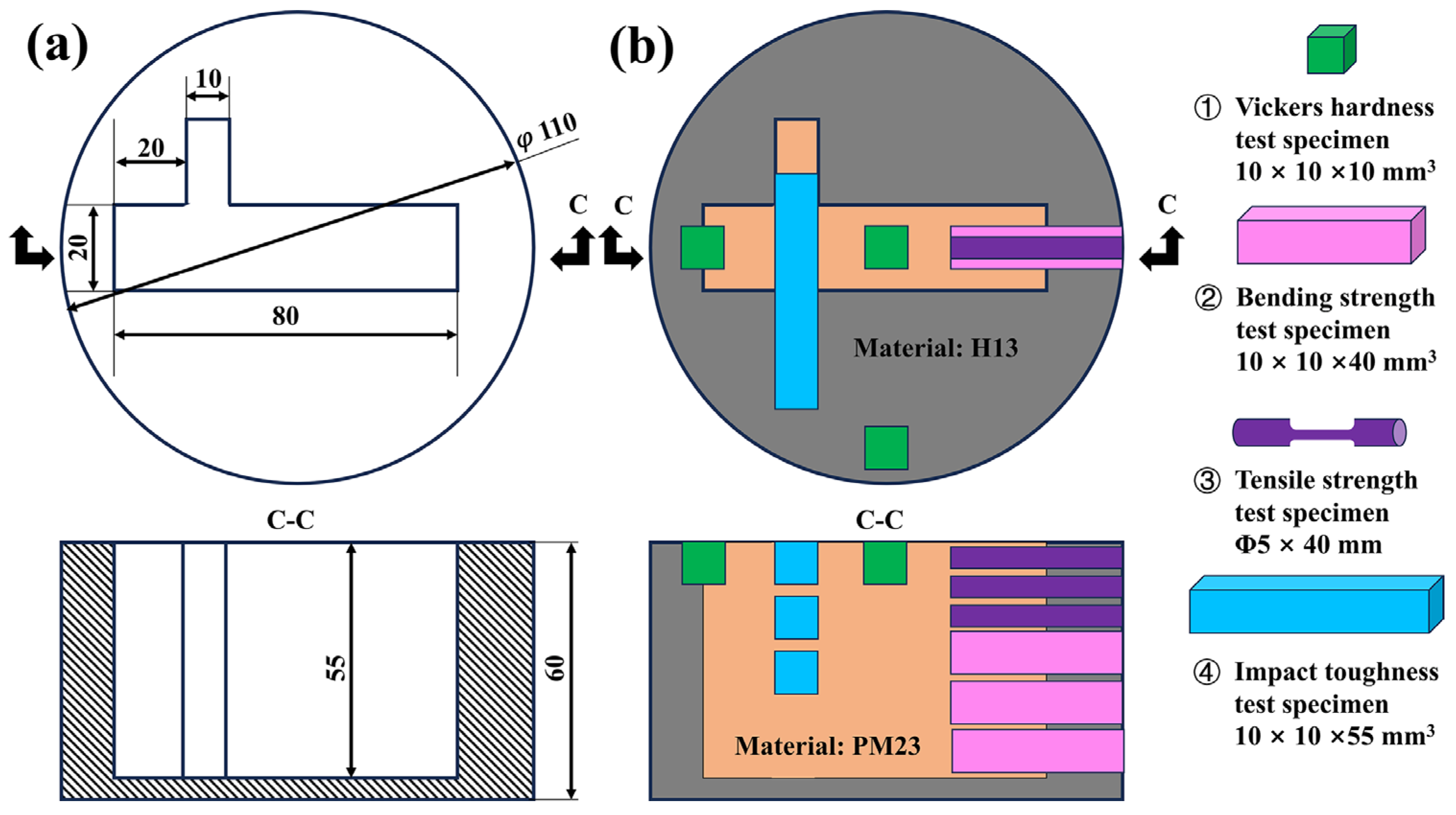
2.1. Materials

The two types of materials utilized in the present study were PM23 HSS powder and H13 mold steel. Table 1 presents these materials’ nominal chemical compositions, respectively. Figure 1 depicts the morphology and characteristics of the PM23 powder, which revealed an MC dendric structure on an iron matrix. The morphology of PM23 powders presented a spherical shape and a small number of satellited powders. It should be noted that the PM23 powder used in this study had a D50 of 127 μm.
As shown in Figure 2, the mold that needed to be repaired had a 110 mm outer radius, and its complex inner cavity shape and dimensions are shown in Figure 3. The dimensions of the molds in this experiment were similar to those used for manufacturing complex aluminum alloy parts, and the shape of the inner cavity of the mold is presented as an inverted T shape. For the details of dimensions, the inner cavity is reported as a 10 × 80 × 50 mm3 plate, with a 15 × 8 × 50 mm3 flank at 20 mm of the plate in the length direction. Two kinds of inner cavity surface were investigated: a machined state (MS) and a sandblasted state (SS). The inner cavity was sandblasted for 15 s at an angle of 65°, and the working distance from the sandblast nozzle to the inner cavity surface was about 200 mm. The molds filled with PM23 powder were placed into low-carbon steel capsules after vacuuming and vibrating.

2.2. Repair Method and Heat Treatment

The capsules were processed via HIP using an 1150 °C sintering temperature and 130 MPa of pressure. In the HIP process, the as-sintered billets were slowly cooled in the HIP furnace to 200 °C before being subjected to the air, with an average cooling rate of about 5 °C/min throughout the process. The HIP parameters have been referenced in other studies on consolidation parameters for PMHSS [19,20,21], and the pressure was reduced (by about 20–30 MPa), taking into account that damaged molds are more susceptible to secondary damage at high pressures. After the consolidation process, the as-HIP capsules were subjected to a pre-heating procedure (550 °C and 850 °C for ~10 min), and finally, austenitized at 1150 °C. The triple tempering treatment was conducted at 560 °C for 60 min. During austenitization, quench oil was used as the cooling medium, with a cooling rate of approximately 200 °C/min, while the cooling medium during three-stage tempering was air, with a cooling rate of about 10 °C/min. The capsules and decarburization surfaces were removed using the wire CUT EDM process. Consolidation and heat treatment curves are exhibited in Figure 4.

2.3. Characterization and Mechanical Tests

In the current study, the test specimens were obtained via wire-cutting using the electrical discharge machining of heat-treated, repaired molds. The sampling positions of the specimens are illustrated in Figure 1.
The SEM specimens with dimensions of 10 × 10 × 10 mm3 were ground and polished via the traditional method (400–3000 SiC sandpaper and diamond suspension). The densities of the distinctive regions were measured five times to acquire an average value using ASTM B962-17 Archimedes’ method (for sintered powder metallurgy products). Surface roughness parameters were measured using a surface roughness tester (TR200, Beijing Hangoo Precision Instrument Co., Ltd, Beijing, China) with a precision of 0.01 μm and a sample length of 0.8 mm, and at least five measurements were repeated to acquire the average value (Ra, Rz, Rp, and Rv). The morphology and microstructure of the repaired molds were observed using an SEM (Phenom XL G2, Thermo Fisher Scientific Inc., Waltham, MA, USA) operating at 5 kV. For the qualitative analysis of phase composition, various specimens were analyzed using an X-ray diffraction (XRD, TTR3, Rigaku Corp., Tokyo, Japan) technique with Co Kα radiation. The vibration-polished (VibroMet 2, Buehler Company, Lake Bluff, IL, USA) samples with dimensions of 8 × 8 × 5 mm3 were further analyzed via the EBSD (electron backscatter diffraction) technique to clarify the microstructure characteristics of the bonding regions (grain boundaries and orientation). The working parameters of the instrument (EDAX detector, EDAX Corp., Pleasanton, CA, USA; OIM 6.2 software) were currents of 15 kV and 1.5 nA, a tilt angle of 70°, and a scanning step size of 100 nm.
Vickers hardness measurements (XHVT-1000Z, Shanghai Shangcai Testing Machine Co., Ltd, Shanghai, China) were performed on the polished surfaces of the specimens with dimensions of 10 × 10 × 5 mm3, and 7 measurements were conducted to acquire the average data after excluding the maximum and minimum hardness data. The impact toughness measurements (JB-300B, Jinan Shijin Testing Machine Co., Ltd., Jinan, China) of the specimens with dimensions of 10 × 10 × 50 mm3 were taken, and at least 3 measurements were repeated to calculate the reliable mean data. The tensile and bending properties were tested with a universal testing machine (WDW-300E, Jinan Shijin Testing Machine Co., Ltd., Jinan, China), and at least 3 measurements were repeated to collect the representative average data.
In another test of the service performance of the repaired molds, the polished wire-cut samples were aged under argon atmosphere protection at 550 °C for 120, 240, 480, 960, and 1920 min, respectively, and tested for Vickers hardness in the bonding region and in the upper and lower 40-micron regions.

3. Results

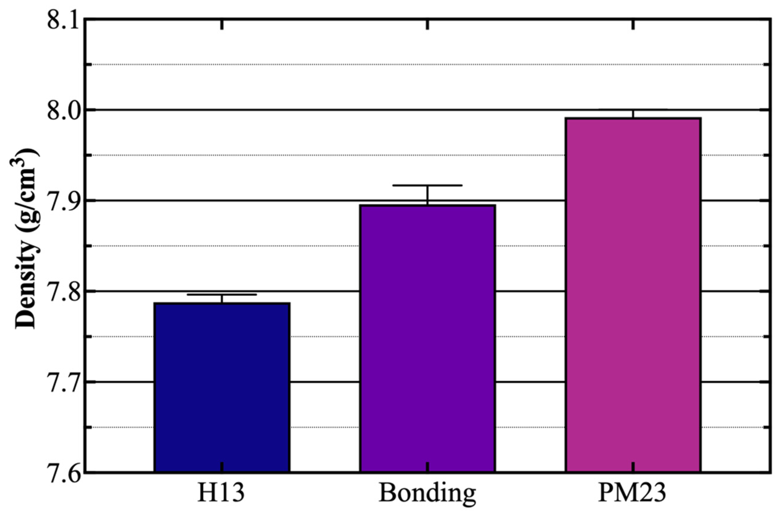
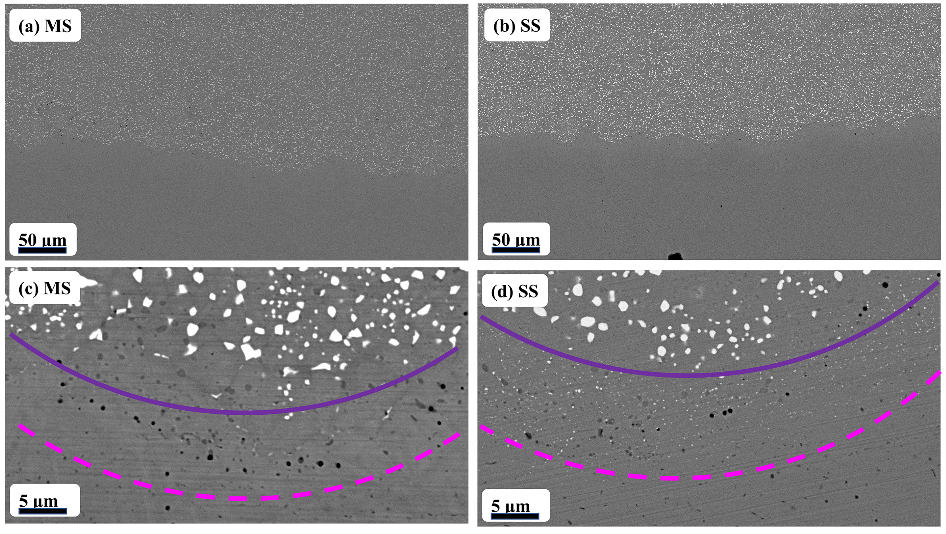
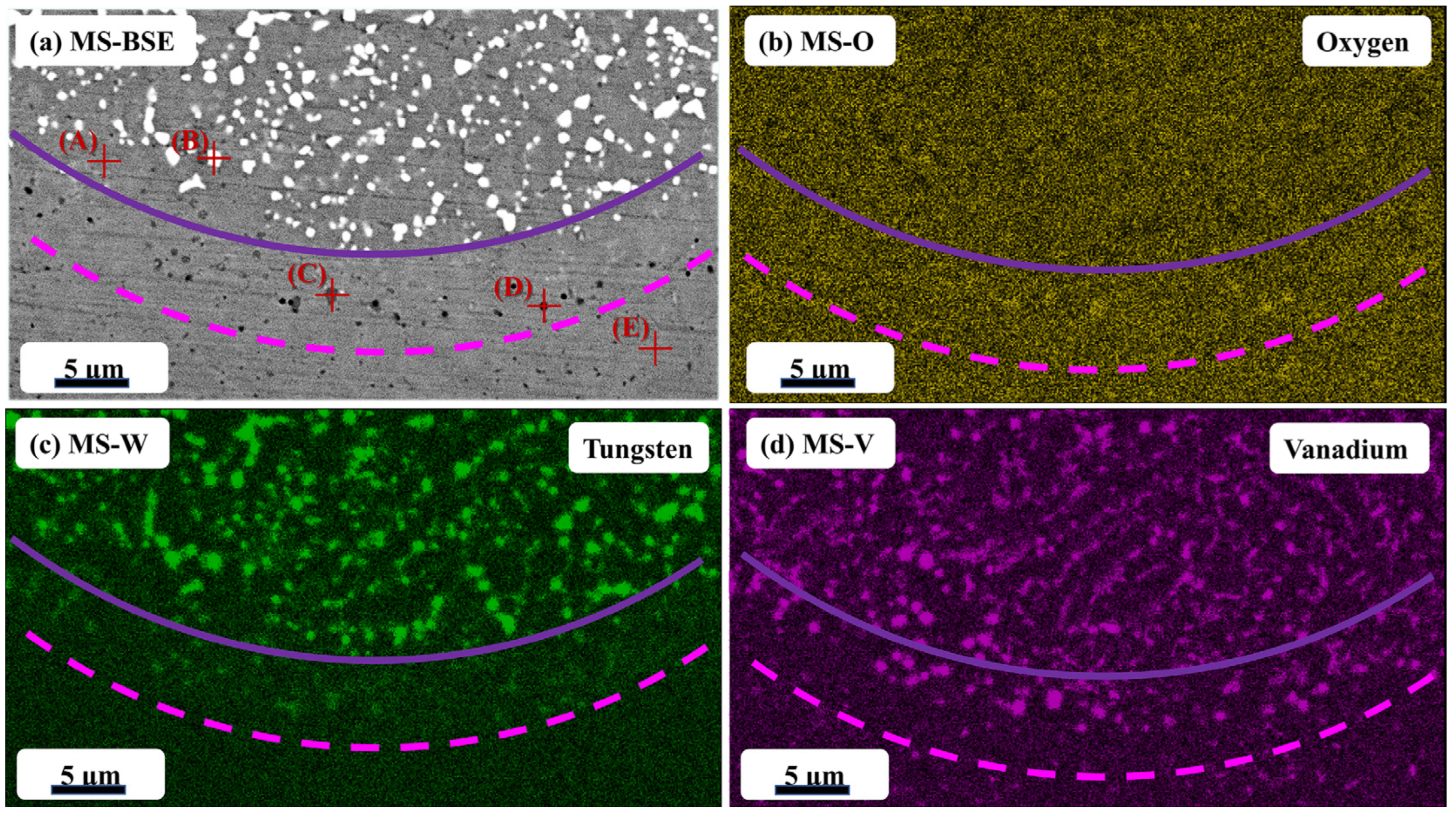
3.1. Surface Roughness, Density, and Microstructure

The surface roughness of the current H13 inner surface and related research are listed in Table 2. The sandblasting process has enhanced the roughness of the H13 inner surface from 0.45 ± 0.05 μm Ra to 3.46 ± 0.65 μm Ra. Only note that the data for Rz and Rv increased by a factor of nearly six, indicating that the sandblasting process has a significant effect on the overall internal surface morphology. The Rp data only shows a two-fold increase, indicating that the sandblasting process also has a significant effect on the maximum contour peak height. Other studies on the surface roughness of AISI 1045 via the sandblasting process also support that the sandblasting process significantly enhances the Ra value, and lowering the blast angle parameter facilitates the reduction of Ra data [22,23].
The densities of various regions are illustrated in Figure 5. Notably, the HIP process enables the preparation of higher-density products. Thus, the density of the PM23 region (7.98 g/cm3) is close to that of the theoretical PM23 material (8.00 g/cm3). The density in the H13 region is 7.79 g/cm3, which is similar to the theoretical density. The density of the bonding region (7.89 g/cm3) represents almost the average of the two regions, and the pores in the bonding region contributed to its increased error. From the results, it is obvious that the HIP process could repair the mold at a high density. Figure 6 exhibits the micro and macro graphs of the bonding regions in two states. According to the captured images, the two materials presented a strong bonding region with a few sintering pores.
Figure 7 depicts the XRD patterns of three different regions (the PM23 region, the bonding region, and the H13 region) in the heat-treated sandblasted state sample. Prior to the heat treatment, the PM23 powder was primarily composed of α-Fe, γ-Fe, MC, and M2C, whereas the XRD patterns of the sandblasted state sample PM23 region primarily contained diffraction peaks of α-Fe, γ-Fe, MC, and M6C. The transformation from M2C to M6C was confirmed, and the presence of α-Fe suggests that tempered martensite formed after the heat treatment. The bonding region phase contained α-Fe, γ-Fe, MC, and M6C, implying that the tungsten-rich particles at the microscale and nanoscale were M6C carbides. α-Fe was also observed in the XRD patterns of the H13 mold region, and the critical enhancement phase was MC carbide. Several HSS-related studies have also reported the mechanism and phenomenon of phase transformation: M2C + γ → M6C + MC [24,25,26].
Figure 8 and Figure 9 show the SEM BSE and EDS analyses results of the MS and SS samples. Table 3 lists the EDS analysis results of the composition of the points marked from (A) to (F) in Figure 8 and Figure 9. The BSE images give an approximate state of the elemental distribution thorough a black-and-white contrast (the precipitation region of the elements with a higher relative atomic number is presented in white, and vice versa). The EDS element mapping figures illustrate the diffusion of elements and the distribution of phases in the bonding region. As shown in Figure 8b and Figure 9b, the distribution of oxygen was only present in the bonding region and showed a point-like phase in the pores. Compared to the MS samples (machined state), the bonding interface of the SS samples (sandblasted state) has fewer point-like oxides, suggesting that the sandblasting process contributed to the reduction of the formation of point-like oxides. The formation of oxides was primarily related to the surface treatment process, and the oxides were usually poorly bonded to the iron matrix, and thus became stress concentration points during service. The XRD analysis results in Figure 7 reveal that the PM23 region consisted predominantly of tungsten-rich M6C carbides and vanadium-rich MC carbides, while the H13 region consisted mainly of vanadium-rich MC carbides. By comparing Figure 8c and Figure 9c, the distribution state of tungsten was found to be consistent with the white region in the BSE picture, which indicates that micron-sized M6C carbide was in the PM23 region. Noticeably, the distribution of tungsten was also visible in the bonding region of the SS samples, which indicates that the sandblasting process could facilitate the formation of nanoscale M6C carbides in the bonding region. By analyzing Figure 8d and Figure 9d, the distribution of vanadium was more evident in the PM23 region, and vanadium was also distributed in the H13 region, suggesting that the MC carbides were more abundant in the PM23 region. Meanwhile, by comparing the distribution of tungsten, significant amounts of vanadium were found in the bonding region in both MS and SS samples, indicating that vanadium was more likely to diffuse to the bonding interface. Furthermore, by comparing the distribution of oxygen and the EDS points results in Table 3, the presence of vanadium elements in the point-like oxides and pores indicates that vanadium oxide might have formed in the bonding region.
Figure 10 depicted the EBSD analysis of the bonding region. Figure 10a,b shows the detector signal images of the bonding regions with high quantities of hard carbide particles, which were primarily inherited from the vibratory polishing process. The particles in Figure 10a,b, which cross-reference Figure 8 and Figure 9, were mainly M6C and MC carbides. The distribution of carbides in the SS samples was significantly more irregular, which was associated with the sandblasting procedure. Interestingly, the interface of the SS sample had a jagged outline, whereas the interface of the MS sample had a flatter outline. Additionally, vibratory polishing might cause the nanoscale carbides to detach from the bonding region.
Figure 10c,d depicts the distribution of low- and high-angle grain boundaries (LAGBs and HAGBs, respectively). When the substructure size and grain boundary distributions of the PM23 region and H13 region of both states were compared, the PM23 region exhibited a more homogeneous martensite substructure and grain boundary distribution than the H13 region did. The low-density region’s LAGBs were primarily concentrated in the carbides near the locations of the grain boundaries that were close to the HAGBs. This means that the figure depicting the grain’s internal area is relatively clean. As demonstrated in Figure 10e, the proportions of LABGS and HAGBs in the MS sample and the SS sample were similar, suggesting that the cavity inner surface pretreatment had a minimal effect on substructures like LABGs and dislocation densities within the microstructures. However, the percentage of LAGBs in the SS sample was 31.6%, which is higher than that in the MS sample specimen (30.7%), suggesting that the specimen’s interior in the SS condition contains more dislocation defects and distortion energy.
In Figure 10f,g, the matrix microstructures of the tempered H13 region were still dominated by martensite, which are typically distributed in the form of laths. The residual austenite had not yet been completely decomposed, and there was no obvious pattern of grain orientation, but the martensite lath size of the SS sample was slightly smaller than that of the MS sample, suggesting that the sandblasting process refined the surface layer microstructure. Large numbers of dispersed carbide particles, a fine-grained matrix microstructure, and a significant amount of residual austenite were all seen in the tempered PM23 HSS matrix. These observations are consistent with the corresponding regions’ XRD patterns. In particular, the size of the carbides at the PM23 powder’s prior particle boundaries (PPBs) was larger than the carbides precipitated in the PM23 powder particles. Other empirical studies on forged H13 and PM23 independently verified these findings [4,27,28,29,30,31].
Figure 11 exhibits the kernel average misorientation (KAM) map of the bonding region. The blue color in the figure indicates a distortion-free environment, mostly for the matrix microstructures, and the other colors all represent a certain distortion behavior; the green color is mostly distributed in the grain boundary position, the yellow color is mostly distributed in the carbide particles, and the red color is distributed in the composite interface. This is because a strong shear force was generated at the interface due to the need for coordinated deformation in the HIP process, which resulted in the accumulation of more strain energy in the microstructure near the interface and a higher dislocation density value, thus providing more nucleation points for the microstructure to undergo recrystallization.
As observed in Figure 11a,b, it can be seen that there is not much difference in the dislocation density of the microstructure on the H13 steel side, whereas on the PM23 high-speed steel side, due to the more concentrated residual strain after the sandblasting treatment, the strain energy level stored near the interface is the highest, the dislocation density was relatively high, the microstructures underwent recrystallization to a higher degree, and the cumulative aberration energy is higher than that of the MS sample, which corresponds to the analysis of the high–low-angle grain boundaries mentioned above.

3.2. Mechanical Properties

Figure 12 displays the red hardness (550 °C) histogram of the SS sample. Along with the increase in the red hardness test time, the average hardness of the mold appeared to increase, and then decrease, with the overall highest average hardness (672.8 HV) appearing at 120 min. Comparing the hardness of the three regions during test, the PM23 region (+40 μm and +20 μm spots) has the highest hardness in the entire test, the H13 region (−40 μm and −20 μm spots) has the next hardest value, and the region with the lowest hardness is the bonding region (0 μm spot). The microstructure of the PM23 region consisted of M6C, MC, and the tempered martensite matrix, which has similar characteristics to PMHSS. The main factors affecting the hardness of powder metallurgy HSS are dispersion strengthening, solid solution strengthening, and densification. For the +20 μm spot, its red hardness is significantly lower than that of the +40 μm spot; by combining the EDS analysis results in Figure 8 and Figure 9, the decrease in hardness could be related to the diffusion of elements leading to the weakening of the effects of dispersion strengthening and solid solution strengthening. Moreover, despite the diffusion of vanadium and tungsten elements occurring in the bonded region, the presence of nanoscale pores results in a limited improvement in hardness, which is similar to that of the H13 region. Corresponding investigations have also discovered that abrupt changes in mechanical characteristics, typically a deterioration in mechanical characteristics, such as the formation of certain intermetallic compounds and nanophases that raise the hardness and lower the toughness, tend to occur at the bonding interface between two metallic materials [16,32,33,34].
Table 4 lists the mechanical characteristics of the bonding region, while contrasting two samples that have undergone various surface treatments. For the SS sample, a higher value was generally obtained. The tensile strength value of the SS sample was 1195.42 ± 61.58 MPa, which was greater than the MS sample’s value of 1158.67 ± 45.23 MPa. The bending strength difference was more than 21%, with the SS sample outperforming the others, with 420.19 ± 14.57 MPa in the bending test. They had similar impact toughness values; the MS sample’s impact toughness was 65 ± 2.78 J, which was 5 J less than the SS samples’ value. Figure 13 depicts the fracture surface of a tensile test bar. This represents the typical fractography of quenched and tempered high-speed steel. The fracture surface was described as a quasi-cleavage fracture with a flat morphology and small facets [35,36,37]; thus, the fracture mode of the material is brittle. Further information regarding the location of the fracture is provided in Figure 13c,d. This shows that the fracture occurred in the PM23 region, and that the bonding region strengthened the metallurgical bond between the PM23 powder and the H13 mold. Nearly all of the fracture surfaces had dents and protruding carbides with a diameter of approximately 1.7 μm. Some nanoscale carbides were also visible.

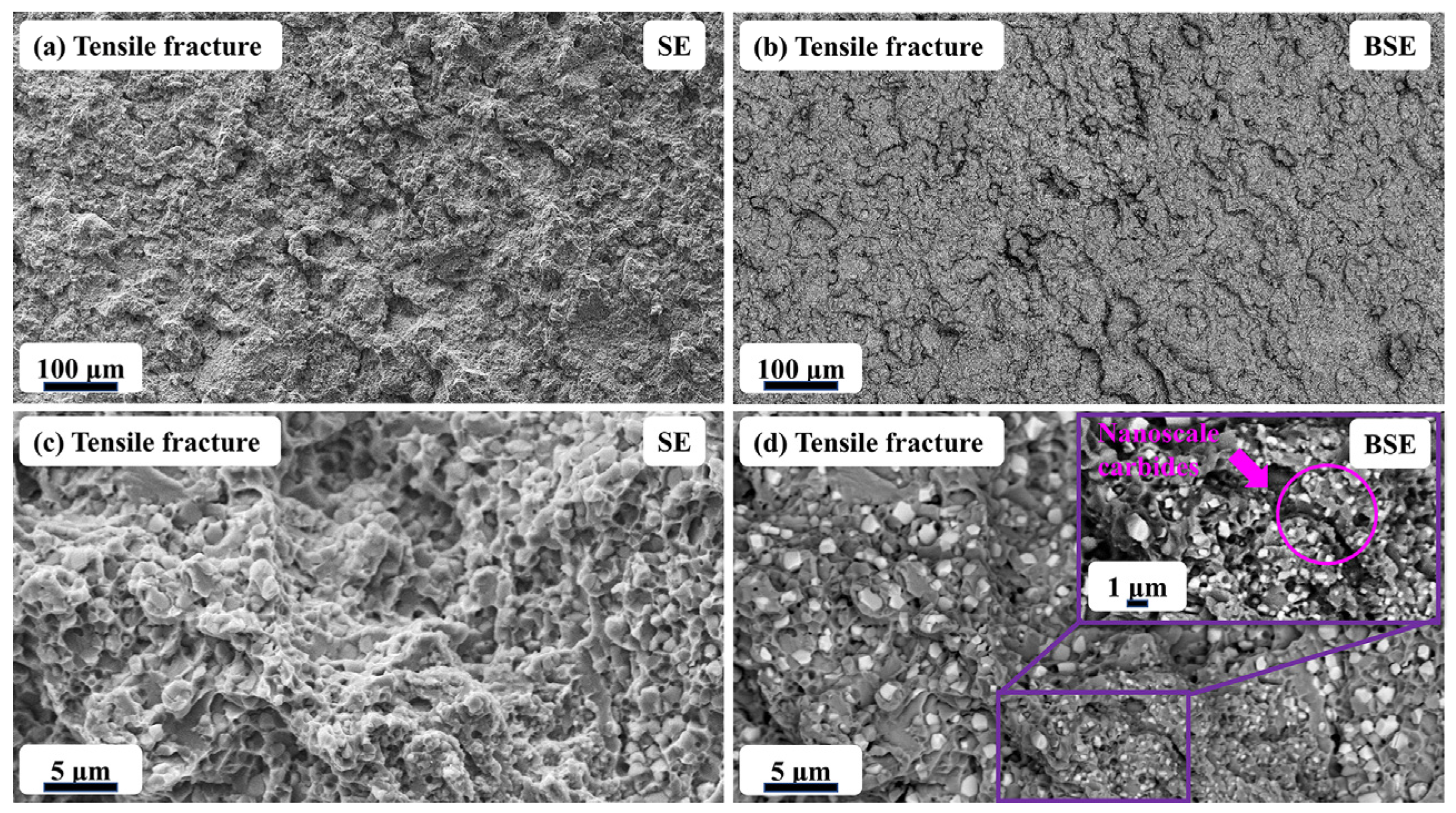
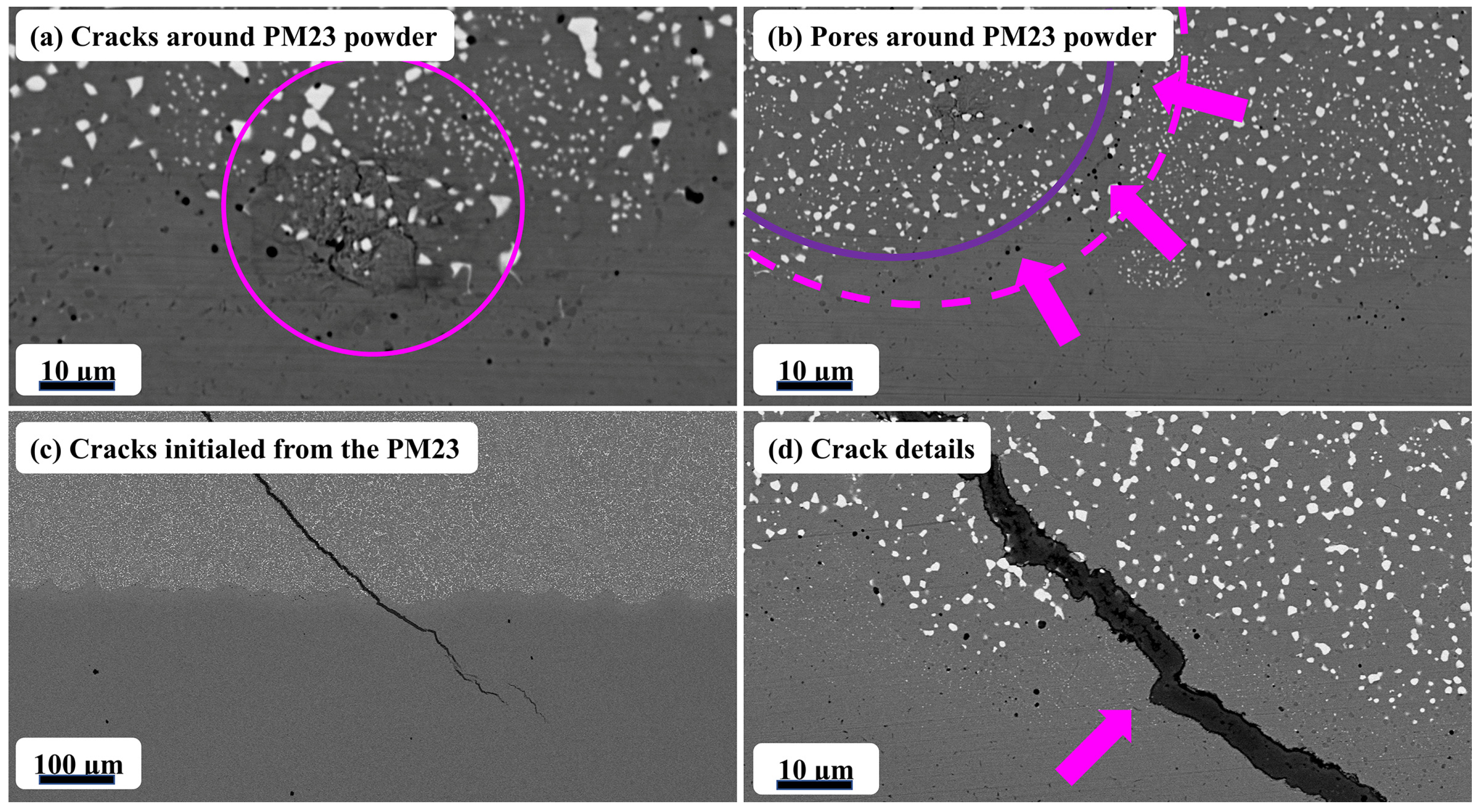
3.3. Defects and Failure Forms

Figure 14 shows the two typical powder-related defects of the repaired molds. As illustrated in Figure 14a, the discontinuity of the interface was witnessed around the powder, with a diameter of around 10 μm, and the precipitated carbides were not distributed evenly in the circled PM23 high-speed steel powder. To acquire an excellent repaired interface, the amount of the powder with a small diameter (≤10 μm) should be controlled. As exhibited in Figure 14b, nanoscale pores were not only captured around the interface, but were observed around the PPBs of the PM23 high-speed steel powder, and the distribution of these pores might influence crack nucleation and growth. Cracks are the one of the major failure forms of molds. Figure 14c depicts a crack that initialed from the PM23 side and went through to the H13 side, and its growth, which does not run along the interface, confirms the matched performances of PM23 and H13. A magnified microstructure of a crack and an interface is presented in Figure 14d; on the PM23 side, the crack grew along the carbides, which was attributed to the poor cohesion of martensite and M6C. In the interface region, the direction of the crack slightly altered, which could be explained by the occurrence of nanoscale M6C and pores. On the H13 side, limited crack growth also supports that the H13 mold retained toughness under the heat treatment.

4. Conclusions

In this study, damaged H13 molds were repaired with PM23 powder via HIP, and the effect of the surface treatment on the interface and mechanical properties was also investigated. The following conclusions can be drawn:
  • HIP technology enables the repair of H13 molds with PM23 powder with a high density.
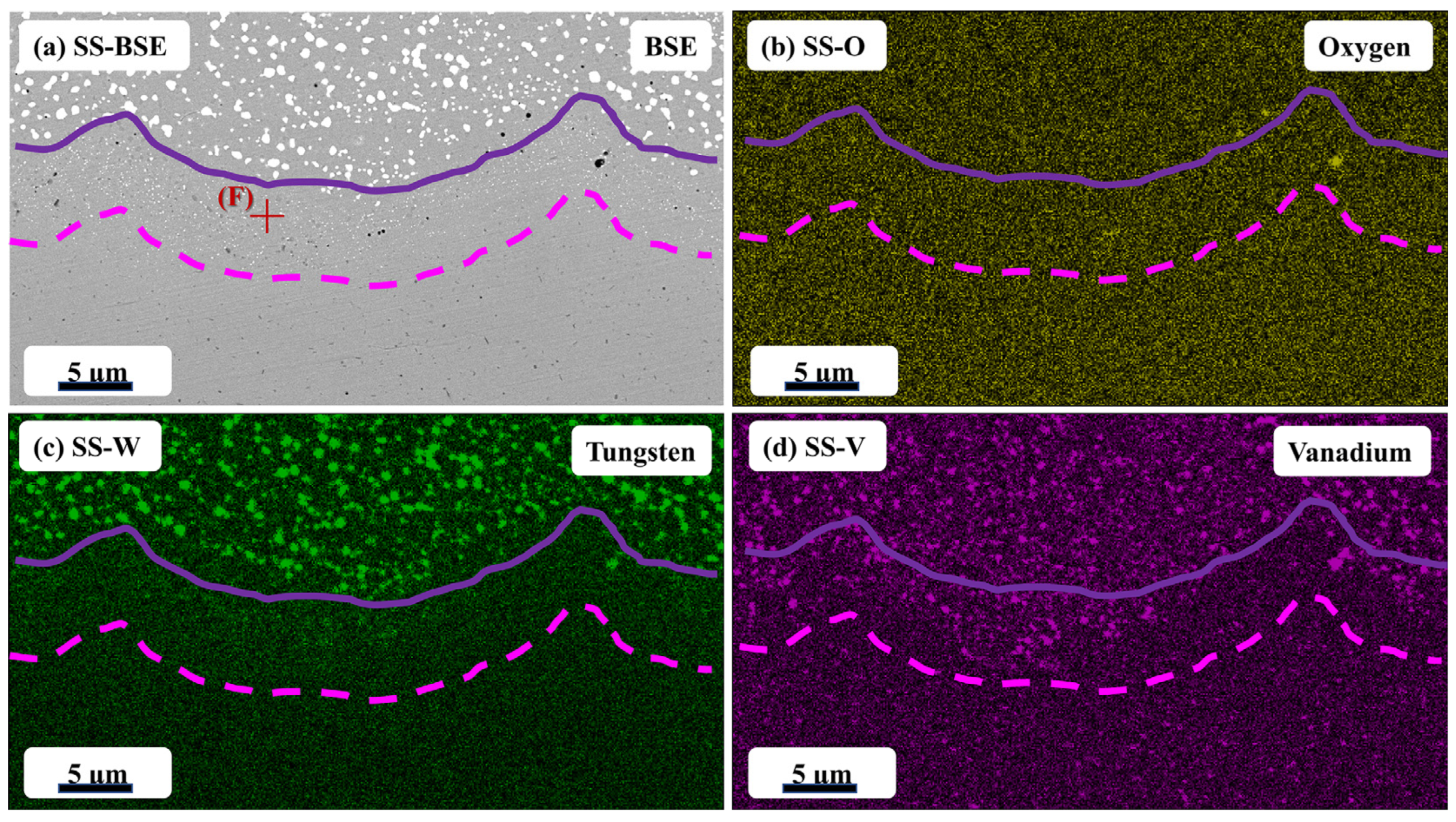
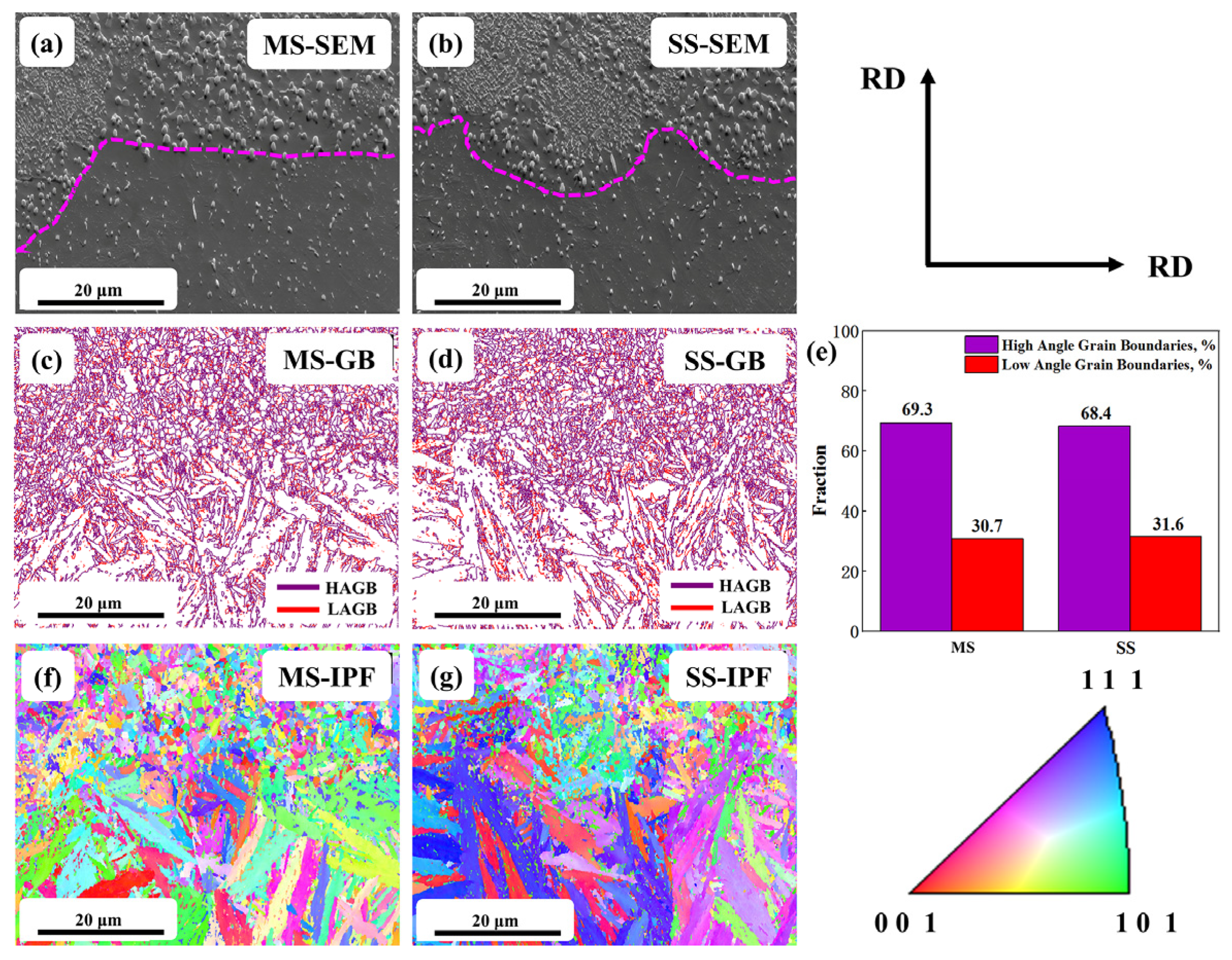
  • The repaired mold is divided into three main feature regions: the PM23 region with distributed carbides (M6C and MC), the bonding region with nanoscale carbides, and the H13 region with MC carbide. Compared with the machined state sample, the bonding interface is more irregular and jagged in the sandblasted state sample, the number of nanoscale carbides higher, and there are more low-angle grain boundaries.
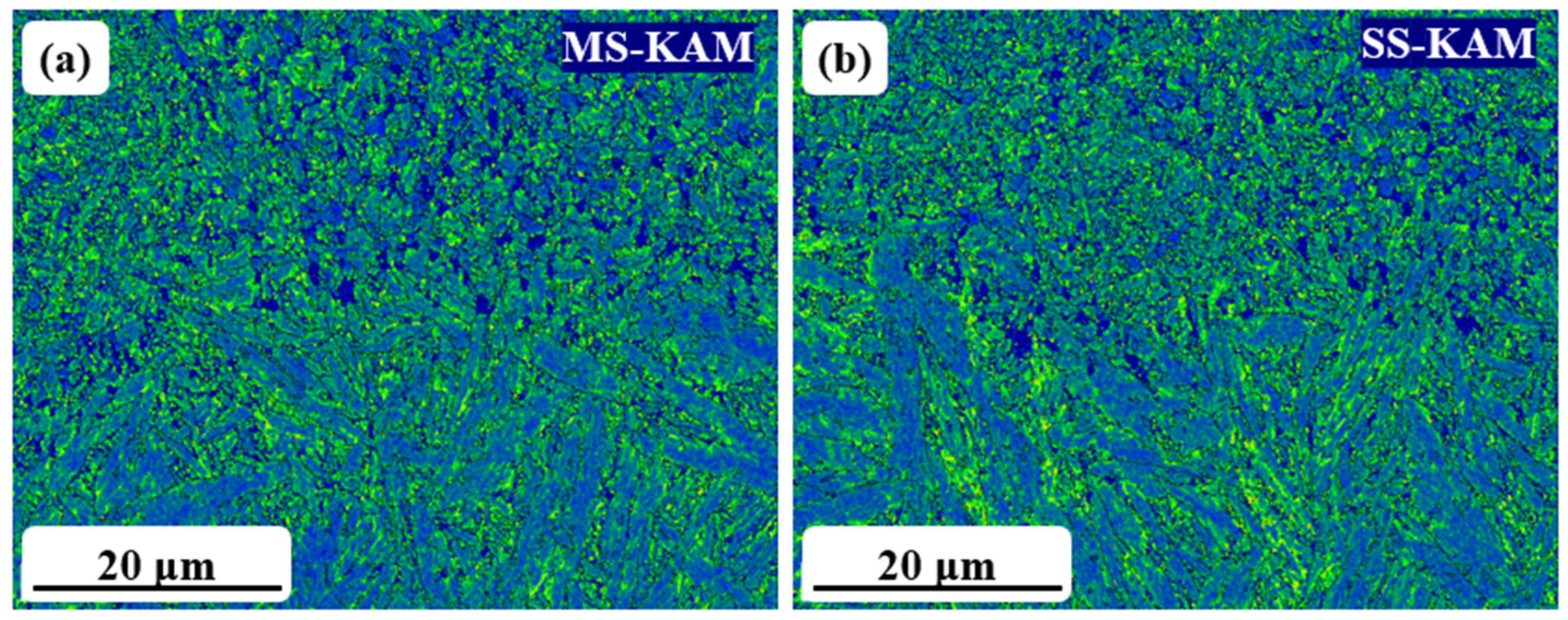
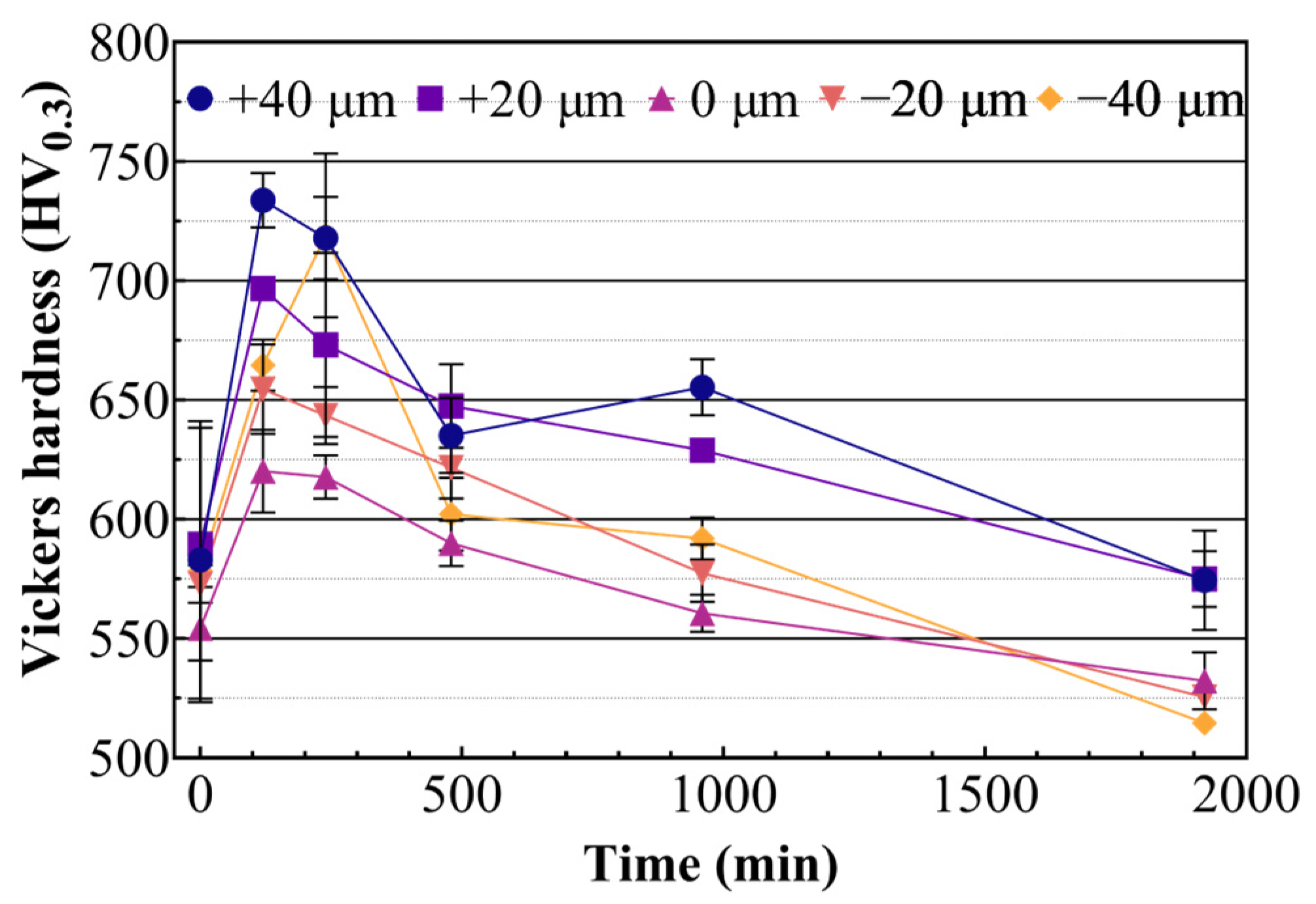
  • The hardness of the molds surface was enhanced with the PM23 materials, and the hardness of the PM23 region after 960 min of red hardness testing was still close to 600 HV. Furthermore, the EBSD and three toughness tests indicate that the application of the sandblasting process is beneficial for the bonding strength of these two materials. The results indicate that the repair method with HIP and sandblasting is effective.
  • There are two forms of defects that occur in this method of repairing molds; one is microcracking due to the poor bonding of fine powders, and the other is powder boundary microporosity due to PPB. Therefore, optimizing the powder particle size is a reasonable means of improving this repair method. In addition, the mold failure mode was analyzed, it mainly originated from the cracking of PM23, and the direction of the cracks ran along the carbide expansion of the H13 mold.

Author Contributions

Conceptualization, X.G. and Q.M.; methodology, X.G.; validation, X.G.; formal analysis, X.G.; investigation, X.G.; resources, X.G.; data curation, X.G.; writing—original draft preparation, X.G.; writing—review and editing, X.G.; visualization, X.G. and Q.H.; supervision, X.G.; project administration, X.G., M.W. and Y.C.; funding acquisition, X.G. All authors have read and agreed to the published version of the manuscript.

Funding

This research was funded by National Science and Technology Major Project of China, grant number 2018ZX04028001-005.

Data Availability Statement

The data are available upon request from the corresponding authors.

Conflicts of Interest

The authors declare no conflict of interest.

References

  1. Wen, Z.; Dejun, K. Effect of Low Temperature Plasma Nitriding on Salt Spray Corrosion and Electrochemical Corrosion of H13 Hot Work Mould Steel. Int. J. Electrochem. Sci. 2018, 13, 8376–8387. [Google Scholar] [CrossRef]
  2. Hao, J.; Hu, F.; Le, X.; Liu, H.; Yang, H.; Han, J. Microstructure and high-temperature wear behaviour of Inconel 625 multi-layer cladding prepared on H13 mould steel by a hybrid additive manufacturing method. J. Mater. Process. Technol. 2021, 291, 117036. [Google Scholar] [CrossRef]
  3. Sun, Y.; Wang, J.; Li, M.; Wang, Y.; Li, C.; Dai, T.; Hao, M.; Ding, H. Thermal and mechanical properties of selective laser melted and heat treated H13 hot work tool steel. Mater. Des. 2022, 224, 111295. [Google Scholar] [CrossRef]
  4. Du, X.; Liu, X.; Shen, Y.; Liu, R.; Wei, Y. H13 tool steel fabricated by wire arc additive manufacturing: Solidification mode, microstructure evolution mechanism and mechanical properties. Mater. Sci. Eng. A 2023, 883, 145536. [Google Scholar] [CrossRef]
  5. Kirchner, A.; Klöden, B.; Franke-Jurisch, M.; Rauh-Hain, L.I.; Weißgärber, T. Manufacturing of Tool Steels by PBF-EB. Metals 2021, 11, 1640. [Google Scholar] [CrossRef]
  6. Li, L.; Cai, Z.; Wu, X. Effect of Silicon on Thermal Stability of 4Cr3Mo2V Hot-Work Die Steel. Metals 2023, 13, 100. [Google Scholar] [CrossRef]
  7. Zhu, Y.; Chen, J.; Li, X. Numerical Simulation of Thermal Field and Performance Study on H13 Die Steel-Based Wire Arc Additive Manufacturing. Metals 2023, 13, 1484. [Google Scholar] [CrossRef]
  8. Priarone, P.C.; Campatelli, G.; Catalano, A.R.; Baffa, F. Life-cycle energy and carbon saving potential of Wire Arc Additive Manufacturing for the repair of mold inserts. CIRP J. Manuf. Sci. Technol. 2021, 35, 943–958. [Google Scholar] [CrossRef]
  9. Preciado, W.T.; Bohorquez, C.E.N. Repair welding of polymer injection molds manufactured in AISI P20 and VP50IM steels. J. Mater. Process. Technol. 2006, 179, 244–250. [Google Scholar] [CrossRef]
  10. Heogh, W.; Yeon, S.M.; Kang, D.-S.; Park, S.; Park, S.; Ryu, K.; Sun, J.; Ji, L.; Son, Y.; Choi, K.; et al. The design and additive manufacturing of an eco-friendly mold utilized for high productivity based on conformal cooling optimization. Mater. Des. 2022, 222, 111088. [Google Scholar] [CrossRef]
  11. Hu, Q.; Wang, M.; Chen, Y.; Si, Z.; Zhang, D. Effects of sintering temperatures on the microstructure and mechanical properties of S390 powder metallurgy high-speed steel. Front. Mater. 2023, 10, 1198776. [Google Scholar] [CrossRef]
  12. Hu, Q.; Wang, M.; Chen, Y.; Liu, H.; Si, Z. The effect of MC-type carbides on the microstructure and wear behavior of S390 high-speed steel produced via spark plasma sintering. Metals 2022, 12, 2168. [Google Scholar] [CrossRef]
  13. Meurling, F. Influence of carbide and inclusion contents on the fatigue properties of high speed steels and tool steels. Int. J. Fatigue 2001, 23, 215–224. [Google Scholar] [CrossRef]
  14. Šuštaršič, B.; Kosec, L.; Jenko, M.; Leskovšek, V. Vacuum sintering of water-atomised HSS powders with MoS2 additions. Vacuum 2001, 61, 471–477. [Google Scholar] [CrossRef]
  15. Hu, Q.; Chen, Y.; Wang, M.; Ge, X.; Liu, H.; Zuo, L.; Zhang, D. Quantitative investigation of influence of Al2O3 non-metallic inclusions on bending strength of powder metallurgy highspeed steel. J. Phys. Conf. Ser. 2022, 2200, 012025–012030. [Google Scholar] [CrossRef]
  16. Le, J.; Yang, J.; Yin, H.; Samarov, V.; Gandy, D.; Lou, X. SA508 low alloy steel to 316L stainless steel dissimilar metal joint made by powder metallurgy hot isostatic pressing. Mater. Sci. Eng., A 2023, 875, 145060. [Google Scholar] [CrossRef]
  17. Viala, J.C.; Peronnet, M.; Barbeau, F.; Bosselet, F.; Bouix, J. Interface chemistry in aluminium alloy castings reinforced with iron base inserts. Compos. Part A 2002, 33, 1417–1420. [Google Scholar] [CrossRef]
  18. Li, X.; Ye, J.; Zhang, H.; Feng, T.; Chen, J.; Hu, X. Sandblasting induced stress release and enhanced adhesion strength of diamond films deposited on austenite stainless steel. Appl. Surf. Sci. 2017, 412, 366–373. [Google Scholar] [CrossRef]
  19. Benito, S.; Boes, J.; Matsuo, M.; Weber, S.; Theisen, W. Uncovering process-structure relationships associated to the hot isostatic pressing of the high-speed steel PMHS 3-3-4 through novel microstructural characterization methods. Mater. Des. 2021, 208, 109925–109929. [Google Scholar] [CrossRef]
  20. Geenen, K.; Röttger, A.; Feld, F.; Theisen, W. Microstructure, mechanical, and tribological properties of M3:2 high-speed steel processed by selective laser melting, hot-isostatic pressing, and casting. Addit. Manuf. 2019, 28, 585–599. [Google Scholar] [CrossRef]
  21. Filho, O.O.A.; Gonzalez, C.H.; Filho, S.L.U.; Oliveira, C.A.N.; Silva, N.D.E.G.; Filho, F.A. Secondary Hardening of an AISI M3:2 High Speed Steel Sinter 23 Hot Isostatic Pressed. Mater. Sci. Forum 2017, 899, 361–365. [Google Scholar] [CrossRef]
  22. Wang, Y.Q.; Yang, H.F.; Han, Q.G.; Fang, L.; Ge, S.R. Tribological and Lubrication Properties of Sandblast-Textured Surfaces with Varied Roughness. Adv. Mater. Res. 2011, 154–155, 1019–1022. [Google Scholar] [CrossRef]
  23. Sen, D.; Chavan, N.M.; Rao, D.S.; Sundararajan, G. Influence of Grit Blasting on the Roughness and the Bond Strength of Detonation Sprayed Coating. J. Therm. Spray Technol. 2010, 19, 805–815. [Google Scholar] [CrossRef]
  24. Lu, L.; Hou, L.G.; Zhang, J.X.; Wang, H.B.; Cui, H.; Huang, J.F.; Zhang, Y.A.; Zhang, J.S. Improved the microstructures and properties of M3:2 high-speed steel by spray forming and niobium alloying. Mater. Charact. 2016, 117, 1–8. [Google Scholar] [CrossRef]
  25. Ghomashchi, M.R.; Sellars, C.M. Microstructural changes in as-cast M2 grade high speed steel during high temperature treatment. Met. Sci. 2013, 18, 44–48. [Google Scholar] [CrossRef]
  26. Ghomashchi, M.R. Quantitative microstructural analysis of M2 grade high speed steel during high temperature treatment. Acta Mater. 1998, 46, 5207–5220. [Google Scholar] [CrossRef]
  27. Bergmueller, S.; Kaserer, L.; Fuchs, L.; Braun, J.; Weinberger, N.; Letofsky-Papst, I.; Leichtfried, G. Crack-free in situ heat-treated high-alloy tool steel processed via laser powder bed fusion: Microstructure and mechanical properties. Heliyon 2022, 8, e10171. [Google Scholar] [CrossRef]
  28. Li, Y.; Wang, Y.; Niu, J.; Liu, S.; Lin, Y.; Liu, N.; Ma, J.; Zhang, Z.; Wang, J. Microstructure and mechanical properties of M2 high speed steel produced by electron beam melting. Mater. Sci. Eng. A 2023, 862, 13–19. [Google Scholar] [CrossRef]
  29. Wu, H.-X.; Ge, C.-C.; Yan, Q.-Z.; Xia, M.; Tian, T.; Zhu, Z.-L.; Hu, Q.-P. Plastic deformation behavior of spray formed superalloy FGH100. Mater. Sci. Eng. A 2017, 699, 156–164. [Google Scholar] [CrossRef]
  30. Ding, H.; Yuan, Z.; Liu, T.; Chen, L.; Zhou, Y.; Cao, Y.; Cao, F.; Luo, R.; Cheng, X. Microstructure and high-temperature tensile behavior of modified H13 steel with the addition of tungsten, molybdenum, and lowering of chromium. Mater. Sci. Eng. A 2023, 866, 144655. [Google Scholar] [CrossRef]
  31. Ding, H.; Cheng, X.; Liu, T.; Cao, F.; Chen, L.; Luo, R.; Zhang, Y.; Zhang, B. Microstructure and high-temperature tensile behavior of spray-formed modified 2000MPa H13 hot work die steel with 0.5 wt% carbon. Mater. Sci. Eng. A 2022, 842, 143102. [Google Scholar] [CrossRef]
  32. Xiao, Y.; Lang, L.-H.; Xu, W.-C.; Zhang, D.-x. Diffusion bonding of Ti—6Al—4V titanium alloy powder and solid by hot isostatic pressing. Trans. Nonferrous Met. Soc. China 2022, 32, 3587–3595. [Google Scholar] [CrossRef]
  33. Xiao, Y.; Lang, L.-H.; Xu, W.-C. Microstructure and mechanical properties of CuAgZn/GH909 diffusion bonded joint fabricated by hot isostatic pressing. Trans. Nonferrous Met. Soc. China 2021, 31, 475–484. [Google Scholar] [CrossRef]
  34. Xiao, L.; Li, S.; Xu, J.; Zhao, Z.; Xiang, H.; Bao, X.; Piao, S.; Peng, Z.; Pan, L.; Liang, X.; et al. Failure mechanism and improvement process of preparing carbide coating on high speed steel by thermal diffusion reaction. Surf. Coat. Technol. 2020, 404, 126398. [Google Scholar] [CrossRef]
  35. Firouzi, A.; Yazdani, S.; Tavangar, R.; Shakerifard, B.; Mohammad, F.K. Austempering of PM HSS ASP2030 for improved fracture toughness. Metall. Res. Technol. 2022, 119, 211–220. [Google Scholar] [CrossRef]
  36. Akhmetov, A.S.; Eremeeva, Z.V. Investigation of the Structure of Sintered Blanks from Powder Mixture of R6M5K5 High-Speed Steel Containing Diffusion-Alloyed Powder. Metallurgist 2022, 66, 299–303. [Google Scholar] [CrossRef]
  37. Lyu, C.; Yao, Y.; Zhang, X.; Luo, Y. Influence of tempering temperature on the microstructure and wear properties of powder metallurgy high-speed steels. Steel Res. Int. 2022, 93, 10–17. [Google Scholar] [CrossRef]
Figure 1. Characteristics of PM23 powder: (a) powder morphology; (b) powder cross section; (c) size distribution; (d) XRD patterns mainly consists of α-Fe, γ-Fe, MC, and M2C.
Metals 13 01783 g001
Figure 2. Schematic diagram of mold repair routes (MS and SS).
Metals 13 01783 g002
Figure 3. Schematic diagram: (a) H13 mold dimensions; (b) sampling position for mechanical tests (mm).
Metals 13 01783 g003
Figure 4. Heat-related curves: (a) HIP; (b) heat treatment.
Metals 13 01783 g004
Figure 5. The density of as-HIP billet (H13 region, bonding region, and PM23 region).
Metals 13 01783 g005
Figure 6. The micrographs of bonding regions: (a) MS macro-region; (b) SS macro-region; (c) MS micro-region; (d) SS micro-region.
Metals 13 01783 g006
Figure 7. The XRD patterns of SS sample after the heat treatment: (a) PM23 region; (b) bonding region; (c) H13 region.
Metals 13 01783 g007
Figure 8. The EDS element mapping analysis of MS bonding region: (a) BSE; (b) Oxygen (O); (c) Tungsten (W); (d) Vanadium (V).
Metals 13 01783 g008
Figure 9. The EDS element mapping analysis of SS bonding region: (a) BSE; (b) Oxygen (O); (c) Tungsten (W); (d) Vanadium (V).
Metals 13 01783 g009
Figure 10. The EBSD analysis of the interface: (a) MS-SEM; (b) SS-SEM; (c) MS-GBs; (d) SS-GBs. (e) Statical analysis of low- and high-angle grain boundaries; (f) MS-IPF; (g) SS-IPF.
Metals 13 01783 g010
Figure 11. The EBSD kernel average misorientation (KAM) analysis of the interface: (a) MS; (b) SS.
Metals 13 01783 g011
Figure 12. The red hardness of repaired regions in the SS sample.
Metals 13 01783 g012
Figure 13. The fracture surface of SS sample tensile test bars: (a) macro-SE; (b) macro-BSE; (c) micro-SE; (d) micro-BSE.
Metals 13 01783 g013
Figure 14. The failure modes of the repaired molds: (a) cracks around PM23 powder; (b) pores around PM23 powder; (c) cracks initialed from the PM23; (d) crack details.
Metals 13 01783 g014
Table 1. The nominal chemical composition of the mold steel and powder (wt.%).
AISICSiMnCrMoVWFe
MoldH130.391.000.415.231.340.98Bal.
PowderPM231.204.984.131.528.12Bal.
Table 2. The surface roughness of the current samples and related research.
Samples and Surface TreatmentsSurface Roughness (μm)
MaterialsTreatmentAngle (°)Time (s)Distance (mm)RaRzRpRvRef.
H13MS0.45 ± 0.054.76 ± 0.993.23 ± 1.022.33 ± 0.62
H13SS65152003.46 ± 0.6523.27 ± 5.457.83 ± 2.0815.44 ± 3.59
AISI 1045PS0.03[22]
AISI 1045SS70–80301003.92[22]
AISI 4130SS9062508.65[23]
AISI 4130SS4562507.93[23]
MS is used for machined state, SS is used for sandblasted state, and PS is used for polished state.
Table 3. Energy-dispersive X-ray spectroscopy (EDS) analysis of the composition of the points marked (A) to (F) in Figure 8 and Figure 9.
PointCOVCrFeMoW
wt.%at.%wt.%at.%wt.%at.%wt.%at.%wt.%at.%wt.%at.%wt.%at.%
(A)2.209.590.802.622.502.573.803.8384.4879.092.101.154.101.17
(B)3.6019.091.204.782.703.383.704.5339.8645.5118.0812.0230.8710.70
(C)5.2022.320.000.0040.8641.384.504.5023.1821.4111.896.3914.394.04
(D)2.7011.444.9015.5915.5015.494.003.9250.3045.845.803.0816.804.65
(E)2.209.620.401.310.100.104.214.2488.4883.001.600.883.000.86
(F)2.2011.470.702.742.402.954.405.3054.1560.7814.199.2721.987.49
Table 4. The mechanical properties of bonding region.
Tensile Strength (MPa)Bending Strength (MPa)Impact Toughness (J)
MS1158.67 ± 15.23345.33 ± 8.0865 ± 2.78
SS1195.42 ± 31.58420.19 ± 14.5770 ± 5.35
Disclaimer/Publisher’s Note: The statements, opinions and data contained in all publications are solely those of the individual author(s) and contributor(s) and not of MDPI and/or the editor(s). MDPI and/or the editor(s) disclaim responsibility for any injury to people or property resulting from any ideas, methods, instructions or products referred to in the content.

