Abstract
This manuscript explores the stiffness and strength of Square Hollow Section (SHS) tubes subjected to localised transverse actions applied to the open side of a rectangular hole created using 3D laser cutting technology (3D-LCT). Understanding the behaviour of this specific detail is crucial as it is a key component in the connections between SHS columns and passing-through IPE beams. The methodology employed in this manuscript involved developing analytical equations to predict both stiffness and strength of this structural element. The provided equations are presented in a straightforward manner and were deduced by applying elasticity principles to structural components. To validate these equations, a parametric analysis was conducted, simulating the response of 27 distinct geometric configurations of the analysed structural detail thanks to the Finite Element (FE) software. Their accuracy was confirmed by comparing the results of these simulations with the outcomes derived from the formulated equations. The primary findings indicated that the proposed equations could predict the stiffness and strength of the studied detail with an average ratio close to 1 when comparing predicted and numerical results, and a coefficient of variation of approximately 10%.
1. Introduction
The last few decades have been characterised by technological and materials engineering innovations, which have also impacted civil engineering, promoting the development of various solutions for rehabilitating existing structures, and designing resilient buildings. For example, on the one hand, there has been increasing use of composite and polymeric materials for seismic retrofitting of buildings [1,2,3,4], while, on the other hand, several innovative seismic-resilient structural systems have been developed to provide solutions capable of withstanding high-intensity seismic events while ensuring full functionality (or minimal damage) in the aftermath of an earthquake [5,6,7,8,9,10,11,12]. Most of these solutions rely on innovative seismic devices such as passive control systems, isolation, or energy dissipation, aiming to preserve the structure from damage or concentrate the damage in easily replaceable components, enabling rapid repair and recovery actions.
Beyond the aforementioned aspects related to materials and resilient design strategies, new technologies were also embraced. One example is represented by 3D laser cutting technology (3D-LCT), which is a technique that offers numerous practical advantages by enabling the precision cutting of steel elements into custom shapes, seamlessly incorporating bevels and holes in a single manufacturing step. In recent years, this innovative method has demonstrated remarkable efficiency, facilitating the rapid and accurate production of structures [13]. Notably, within civil engineering, it has emerged as a highly promising application, particularly for producing components with complex geometries [13]. A recent example includes the ability, explored in recent research endeavours [13], to create complex three-dimensional steel joints featuring circular hollow section (CHS) columns and passing-through IPE beams.
Traditionally, constructing joints between hollow profiles and IPE beams has been fraught with limitations. The conventional approaches involve the following: (i) welding the beam onto the external surface of the column [14,15,16]; (ii) welding plates onto the flanges of the IPE profile, where they intersect with the column [17]; (iii) welding the beam to collar plates that are externally welded or bolted to the column [18,19,20,21]; and (iv) filling the column with concrete while welding the beam to its external surface [22,23,24,25]. The first method is relatively straightforward but lacks the necessary stiffness and strength, making it suitable primarily for pinned or semi-continuous frames [26]. The second and third solutions offer increased strength and stiffness but require additional welds and plates [27,28], leading to sustainability concerns and added connection costs. On the other hand, the final approach involves composite elements and introduces construction delays due to on-site concrete pouring [29,30].
Connections incorporating passing-through beams circumvent the issues associated with these four typical configurations, minimising manufacturing costs (without the need for extra stiffeners and welding) whilst maximising performance in terms of strength and stiffness (yielding rigid partial or full-strength joints). By cutting the tubular profile on two opposing sides to match the passing-through IPE cross section, the beam can cross the hollow column, enhancing stiffness, resistance, and overall aesthetics. Consequently, significant interest has arisen in the technological aspects of constructing these joints [27,28], as well as their mechanical behaviour [31,32].
Starting from 2016, numerous studies have delved into this topic, particularly within the framework of the LASTEICON (Laser Technology for Innovative Connections in Steel Construction) research project [13]. The primary objective of the LASTEICON project is to reduce material usage and costs for hollow structures using 3D-LCT. Consequently, considerable attention has been dedicated to the technological aspects associated with manufacturing such joints [27,28].
In this context, the University of Salerno is currently engaged in a combination of experimental, numerical, and theoretical research endeavours aimed at formulating equations for estimating the strength and stiffness of such connections. These efforts are in line with the methodology prescribed in the current Eurocode 3 part 1.8 [16]. Studies have already been conducted, yielding semi-empirical expressions designed to predict the flexural strength and initial stiffness of connections involving circular hollow section (CHS) columns and passing-through IPE beams [33,34,35,36,37]. In particular, the studies have been carried out according to the component method approach [38,39,40,41]. This methodology enables the determination of the response of a joint by considering the mechanical behaviour of its individual components, which contribute to the connection’s strength and deformability. The component method encompasses three fundamental stages [42]:
- (i)
- Identification of strength and deformability sources. In this initial phase, the various sources of strength and deformability within the connection, which are essentially the joint components, are identified. This identification process relies on a combination of experimental data, engineering judgment, and Finite Element (FE) modelling.
- (ii)
- Mechanical modelling of individual components, which consists of the mechanical modelling of each of the identified components, considering their respective strength and stiffness characteristics.
- (iii)
- Assembly of a mechanical spring model that accurately represents the behaviour of the entire connection. This model is constructed by combining the responses of the individual components, resulting in a comprehensive representation of the joint’s stiffness and strength.
By following these three steps, the component method approach facilitates the evaluation of the joint’s overall performance, allowing for a thorough understanding of how its constituent parts collectively contribute to strength and deformability.
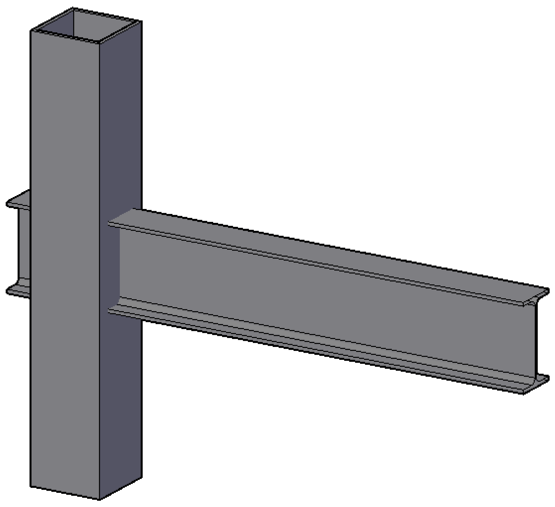
The same strategy is intended to be applied to the case of Square Hollow Section (SHS) columns and passing-through IPE beam connections (Figure 1). The recent development of this solution makes it innovative; however, at the same time, it limits its use since design guidelines are not currently available in existing standards. In fact, the current draft of Eurocode 3 part 1.8 [16] does not provide formulations for such nodes or tends to extend equations defined for other available types, making the procedure over-conservative.
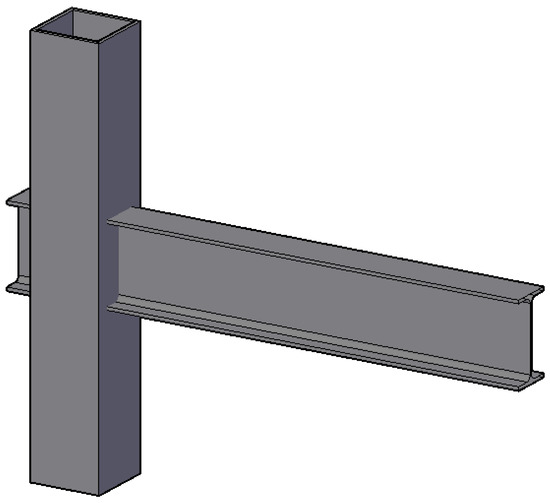
Figure 1.
Connection between SHS column and passing-through IPE beam.
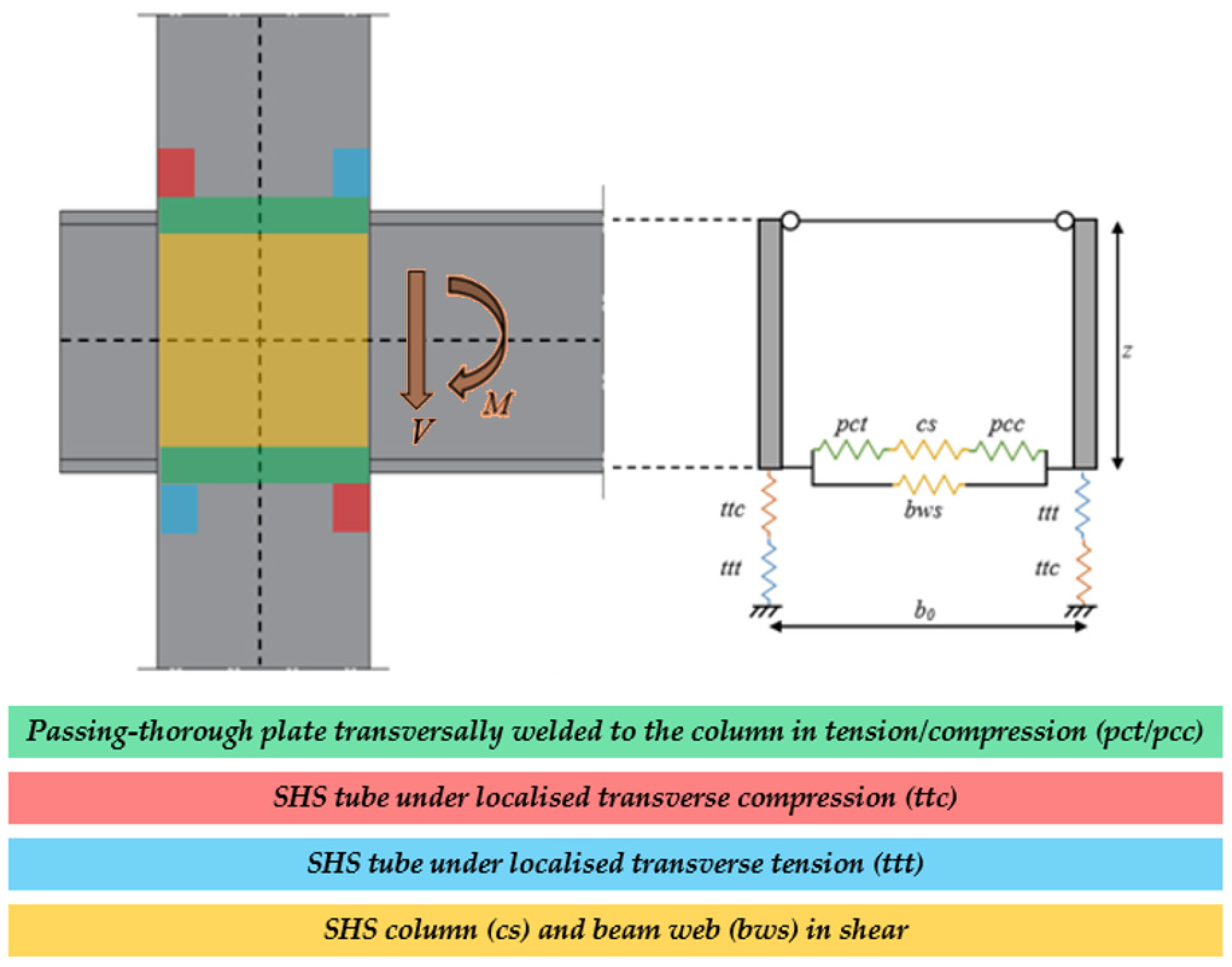
The current investigation presented in this paper belongs to a wider research program characterised by experimental, numerical, and theoretical activities to extend the component method to the case of connections between Square Hollow Section columns and passing-through IPE beams. To achieve this objective, the primary components of this joint were properly identified, as shown in Figure 2:
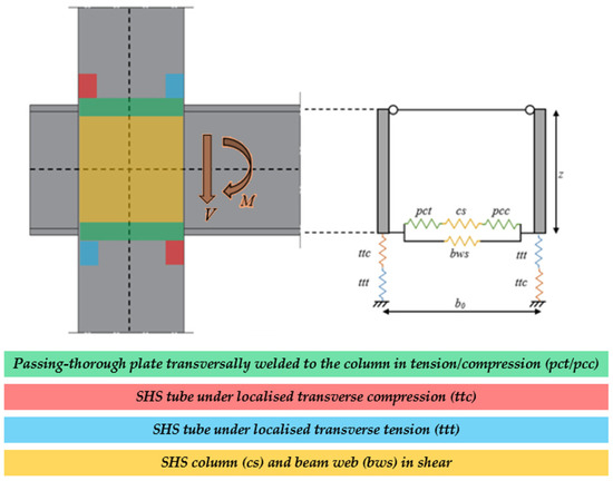
Figure 2.
Nodal components of the connection between the SHS column and passing-through IPE beam.
- -
- The passing-through plate transversally welded to the column in tension/compression (pcc/pct), which is representative of the behaviour of the attachment between the flanges of the beam and the SHS profile.
- -
- The column in transverse tension or compression stresses (ttt/ttc). These components are crucial, particularly concerning the overall stiffness of the connection because the rigid rotation of the beam induces localised stresses at the junctions between the flanges of the IPE profile and the sections of the hollow profile adjacent to the hollow section.
- -
- The column and the beam web in shear (cs stands for the column in shear, while bws is the acronym of beam web in shear).
Figure 2 illustrates the nodal components that constitute the examined connection, clearly showing the topological configuration of the series and parallel links representing the aforementioned components. If a shear force is applied at the free end of the beam, it results in both shear and bending moments at the attachment between the beam and the column face (Figure 2). Consistently with the approaches currently provided by Eurocode 3 [16] concerning traditional connections, and in this case as well, it is intended to proceed with mechanical modelling of the components using elastic perfectly plastic laws.
After identifying the components, it is necessary to examine them in terms of their strength and stiffness. It is important to note that the stiffness and strength of the pcc/pct components have already undergone a comprehensive investigation, as detailed in [43]. This investigation encompassed a combination of experimental, numerical, and analytical analyses. The equations pertaining to the strength and stiffness of the pcc/pct components are presented in Equations (1) and (2) for reference, as follows:
In Equations (1) and (2), is the yield stress, , and are dimensionless parameters defined as , , and , where and are the plate’s width and thickness, while and represent, respectively, the diameter and thickness of the SHS profile.
Instead, no further investigations were conducted concerning the shear components cs and bws. This is because it is feasible to employ the formulas already established in Eurocode 3 part 1.8 [16], which are also presented in this document as Equations (3)–(6) as follows:
In Equations (3)–(6), the partial safety factor is equal to 1, is the shear area of the Square Hollow Section (), is the shear area of the beam web (), is the thickness of the web of the beam, is the transformation parameter equal to , is the distance between the centerlines of the beam flanges, and is the column length.
2. Aim of This Research
The previous paragraph addressed the primary components of connections between SHS columns and passing-through IPE beams. Additionally, it presented strength and stiffness equations associated with specific components, which have been investigated in previous studies [43] and/or are now included in current codes [16].
As a result, to achieve a comprehensive understanding of the whole behaviour of the joint using the component method approach, the study of the ttt/ttc sources of deformability is still required. Consequently, this work aims to investigate these components, which represent the parts of the column locally subjected to transverse actions transmitted from the flanges of the beam. The attention is focused on investigating the stiffness of the analysed components, considering the assumption that , consistently with the evidence dealt with in [37], referring to the case of CHS columns and passing IPE beams. Furthermore, the assessment of the yield and ultimate strength of the ttt/ttc components is also provided.
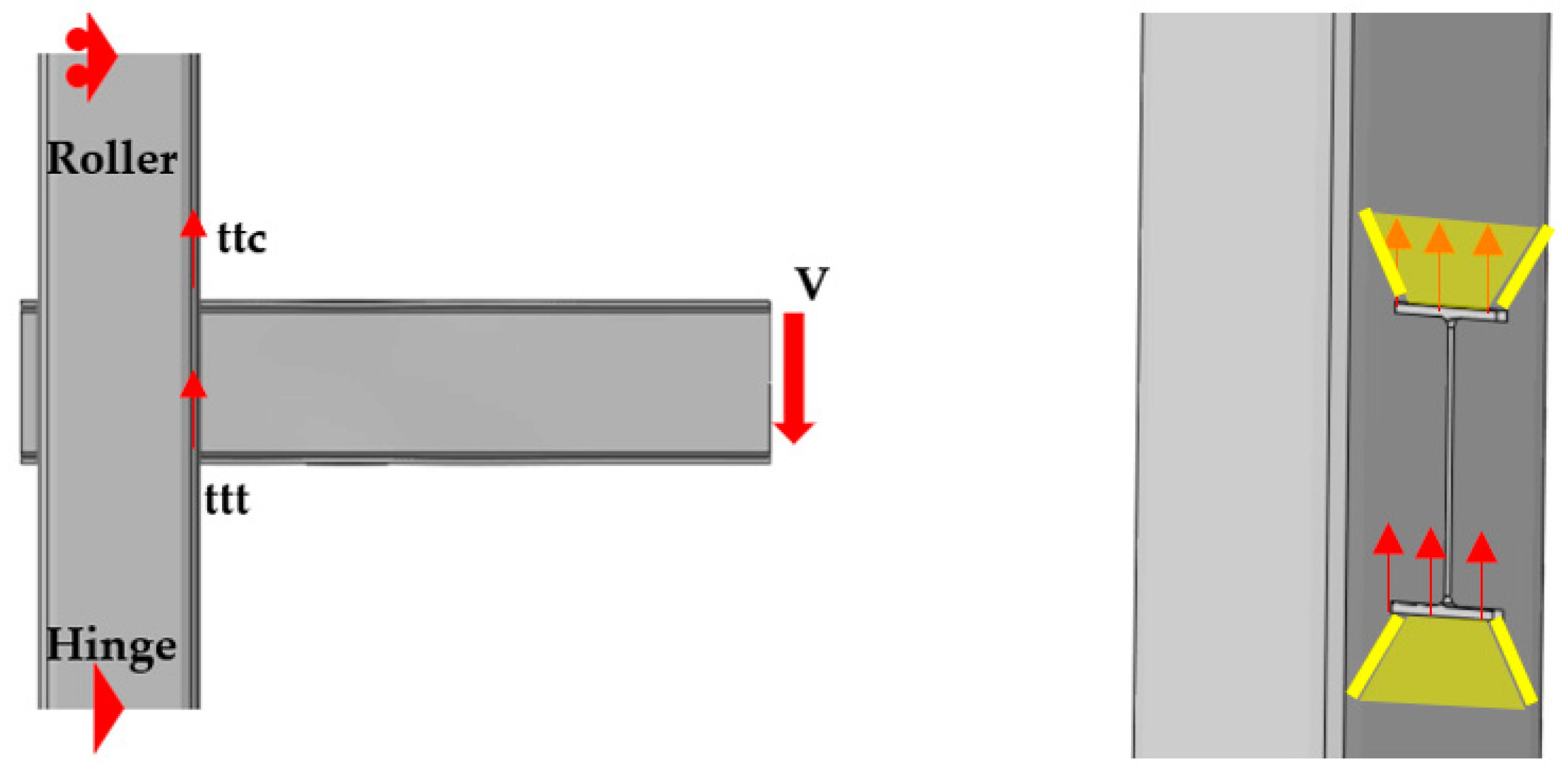
The reason that has led the authors to study the ttt/ttc components relies on the consideration that a single-sided beam-to-column connection is equipped with a hinge and a roller at the column extremities, and exposed to an applied force (V) at the free end of the beam; this force (V) induces beam rotation that has the potential to generate stresses at the attachment between the flanges and the tube along the direction parallel to the column axis. Consequently, these stresses tend to propagate through the thickness of the tube, as illustrated in Figure 3.

Figure 3.
Actions applied to the components ttt/ttc induced by the rigid rotation of the beam.
The significance of this paper lies in the exploration of the stiffness and strength of the nodal components ttt/ttc, as they possess the potential to influence the overall flexural behaviour of the connection between SHS columns and passing-through IPE beams. In fact, there are currently no established guidelines or formulations available for determining the stiffness and strength of these components. This objective is achieved through a combination of theoretical and numerical methods. Specifically, analytical techniques were employed and are discussed in Section 3 to establish formulations for describing the stiffness and strength of the component under examination. On the other hand, Section 4 encompasses the execution of a parametric analysis involving 27 distinct geometric configurations of connections, which are simulated numerically to assess their behaviour. Lastly, in Section 5, the primary findings of this study are discussed.
3. Analytical Activity to Characterise the Stiffness and Strength of the ttt/ttc Components
This section is devoted to the analytical development of equations to predict the initial stiffness and yield strength of the analysed components ttt/ttc.
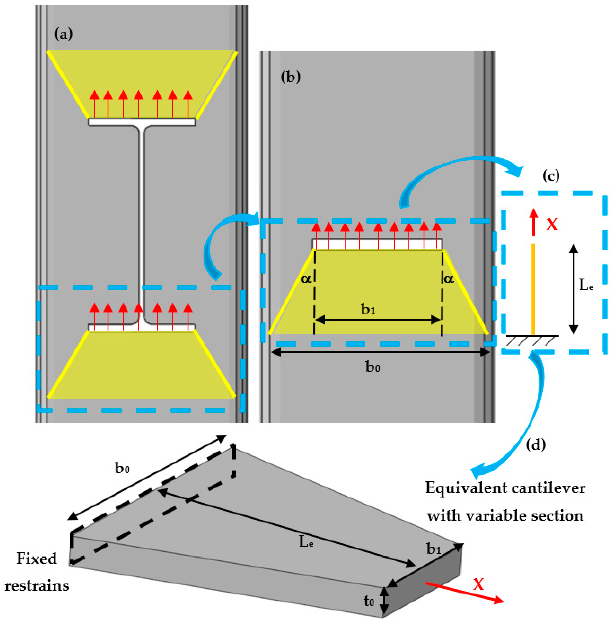
When the analysed components have a response in the elastic range, some of the following assumptions are adopted: The stress diffusion in the tube induced by the rigid rotation of the flanges of the beam (Figure 4a) is analysed according to a simplified scheme (Figure 4b) in which the beam web does not affect the behaviour of the system. Consequently, the obtained scheme can be assumed as a cantilever with a variable section (Figure 4c,d) in which the width varies between the width of the passing plate and that of the SHS tube, and whose length is defined as the distance between the hole and the intersection of the diffusion pattern with the external edges of the SHS profile. The spread of the stresses is characterised by an angle α which usually ranges between 30° and 45°.

Figure 4.
Analytical schematisation: (a) real pattern diffusion in the SHS to I-beam connection; (b) simplified diffusion of stresses in the tube; (c,d) equivalent cantilever with variable section.
The stiffness is evaluated by assuming that the part of the tube interested by these stresses behaves as a cantilever subjected to axial force.
Therefore, the expected elongation of the ideal cantilever is achieved through Equation (7) as follows:
In Equation (7), , and represent, respectively, the elongation, the axial force, and the length of the ideal cantilever. Instead, is Young’s modulus, while represents the initial stiffness of the analysed components ttt/ttc. Since the stresses propagate according to a linear pattern, instead of evaluating the stiffness through the integration method, it is assessed assuming an equivalent section whose area is evaluated by multiplying the thickness of the tube and the average width of the cantilever: , where and represent, respectively, the widths of the column and plate. Instead, trigonometric considerations allow to define the length of the cantilever as .
Consequently, by substituting the previous expressions in Equation (7), it is possible to obtain Equation (8) as follows:
Finally, the last equation can be written in a dimensionless form, shown as Equation (9) as follows:
The equation to predict the initial stiffness of the analysed components was defined, but the doubt related to the angle still remains. For this reason, to avoid leaving this aspect unexplored, it is expected to perform a parametric analysis concerning a set of different geometrical configurations of SHS with holes representative of the passing-through plates and subjected to action parallel to the tubular axis. The initial stiffness of these cases will be evaluated through numerical simulations developed in Abaqus [44] and exploited to calibrate the unknown angle .
However, when the analysed components undergo plastic deformation, it is reasonable to consider, similarly to the case of stiffness, that the strength of the analysed components ttt/ttc can be defined as the strength of a plate with a thickness equal to that of the tube and a width equal to the average of the widths of the hole and the hollow profile as follows:
This formulation is straightforward to define, and as it is evident, it incorporates a term, , which is already present in Equation (8).
4. Finite Element (FE) Simulations
The investigation of the ttt/ttc components is conducted through a parametric analysis involving 27 geometric configurations of tubular profiles with rectangular holes representing the connections between SHS columns and flanges of IPE profiles.
Based on the analytical model presented in the previous paragraph, β is expected to be the only parameter influencing the response of the analysed component. Therefore, the 27 cases were carefully selected by varying β between 0.44 and 0.68 (Table 1).

Table 1.
Parametric analysis.
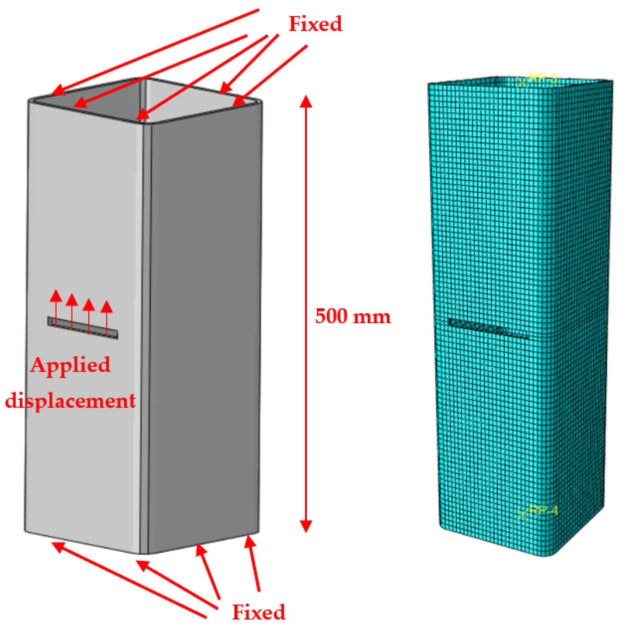
The numerical simulations were carried out using the Finite Element (FE) software Abaqus [44]. Specifically, the adopted scheme refers to the specimen shown in Figure 5, which is an SHS profile with a length of 500 mm, fixed at its ends and characterised at its centre by a rectangular hole whose dimensions depend on the cross shape of the passing plate.
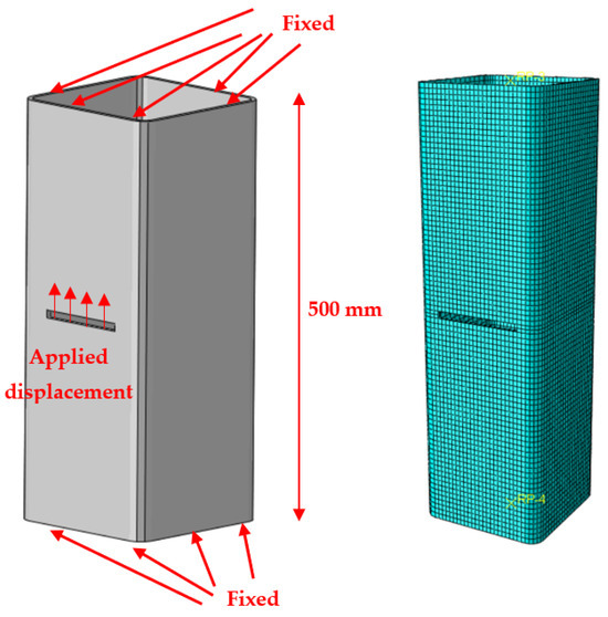
Figure 5.
Mechanical model of the analysed configurations (left) and its mesh (right).
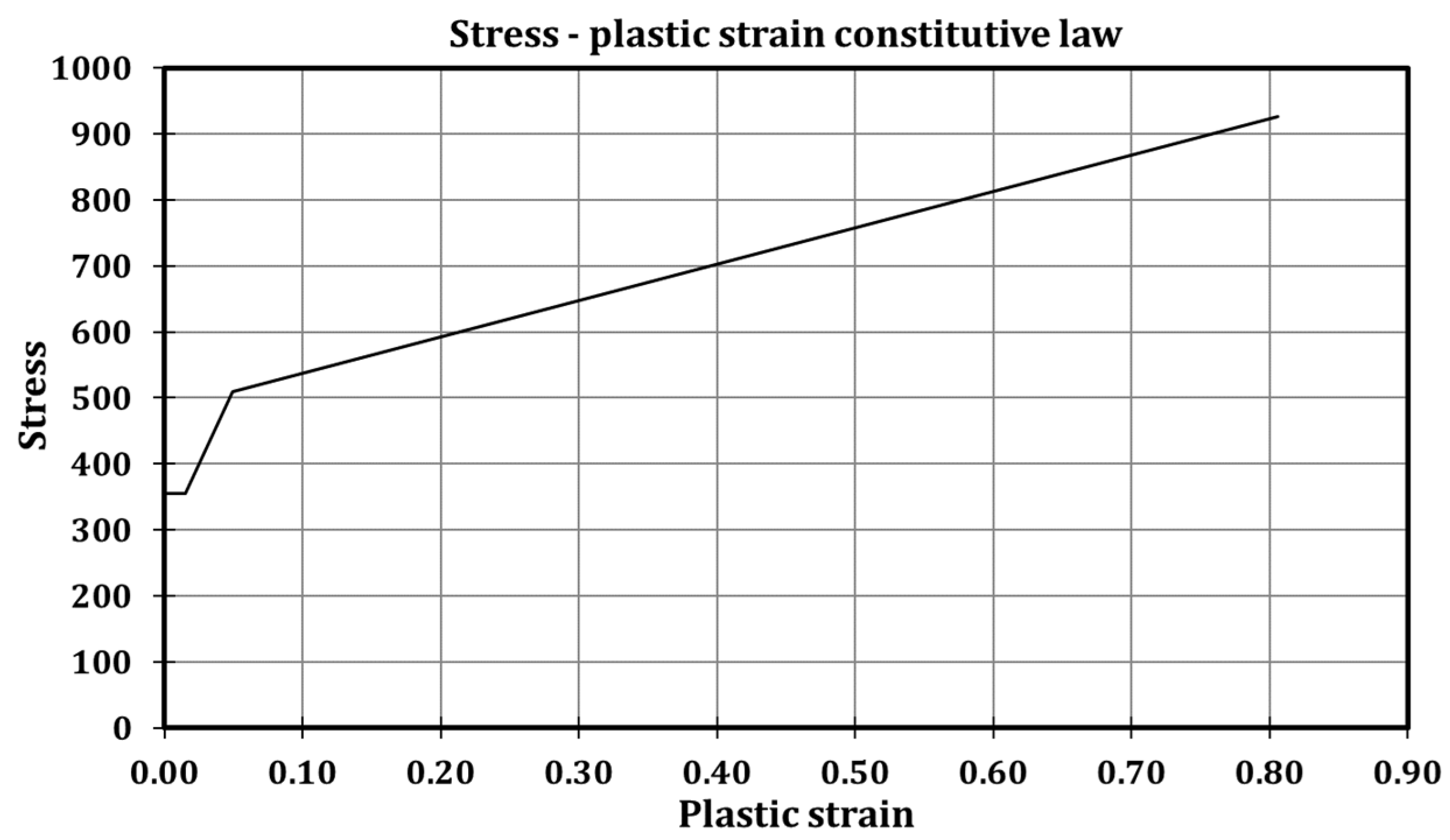
The material properties of the specimen refer to a nominal S355JR steel, whose constitutive model has a quadri-linear shape (Figure 6) according to the suggestion provided by Faella et al. [42]; furthermore, the elastic modulus is 210 GPa, and Poisson’s ratio is equal to 0.30.

Figure 6.
Stress–plastic strain constitutive law for S355JR steel grade according to Faella et al. [42].
The current modelling approach was derived from a numerical model validated in studies referred to connections between CHS columns and passing-through beams and plates [33,34,35,36,37]; consequently, we decided to also include the evolution of material damage in the FE model. In particular, the equivalent plastic strain at fracture was set equal to 2.4 mm, following the recommendations provided by [45,46]. The tubular sections were meshed using 5 mm sized C3D8-type elements (8-node linear brick).
It is worth highlighting that Figure 2 and Figure 3 pertain to the connections between SHS columns and passing-through IPE beams, while Figure 5 narrows its focus to one of the components within the aforementioned connection, labelled as ttt/ttc, and illustrates that the examination of this component can be achieved by evaluating the behaviour of the tube independently, with the application of displacements at the edge of its aperture.
A static solver was employed to perform the analyses, and the loading history consisted in the application of increasing displacements along the thickness of the bottom face of the holes in the direction of the longitudinal axis of the tubular profile, as shown in Figure 5.
For the sake of clarity, Figure 7 shows the in-plane vertical stress distribution in the tubular profile induced at the early stage of analysis related to Case 7 for the characterisation of the initial stiffness of the component.
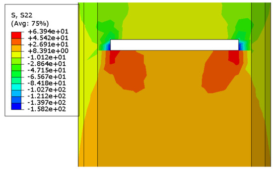
Figure 7.
In-plane vertical stress distribution in the tube (3D view, Case 7).
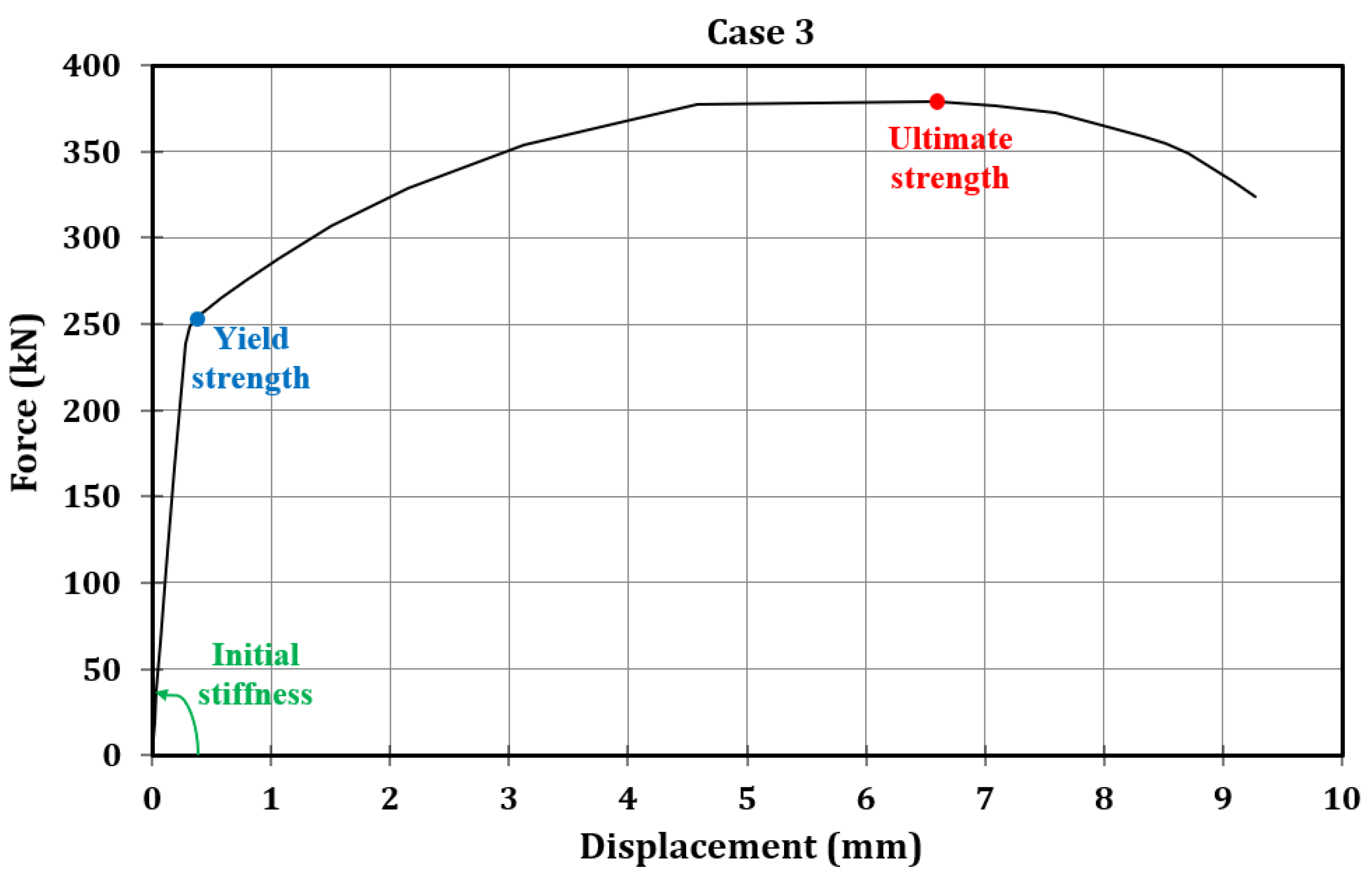
Table 2 summarises the key findings from the parametric analysis, presenting the initial stiffness (kttt/ttc,Abaqus), yield strength (Fy,ttt/ttc,Abaqus), and ultimate strength (Fu,ttt/ttc,Abaqus) observed in each of the 27 analysed cases. Notably, stiffness was determined by assessing the slope derived from the initial points of the force–displacement curve. Yield strength, on the other hand, was calculated as the force at which a 5% plastic deformation occurred, as suggested by Eurocode 3 part 1.5 [47]. Finally, ultimate strength was determined as the maximum force that the analysed components could withstand.
Table 2.
Results of the parametric analysis.
Table 2 reveals that, across the 27 cases, the average ratio between yield and ultimate strength is approximately 67%, with a coefficient of variation of about 2.2%. This observation holds significant potential for future research in this topic. Specifically, if an analytical formulation is developed to determine the yield strength of the components under analysis, this finding suggests a direct method to calculate ultimate strength: multiplying the yield strength by a factor of 1/0.67 (equivalent to 1.5) would yield the ultimate strength.
To enhance clarity, Figure 8 displays the force–displacement curve for Case 3, emphasising the defined key parameters of interest.

Figure 8.
Force-displacement curve related to Case 3.
5. Discussion
Section 3 and Section 4 were devoted, respectively, to deriving an analytical formulation to predict the initial stiffness and yield strength of the analysed component and performing a parametric analysis, through numerical simulations, of a wider set of its geometrical configurations. Instead, this section focuses on evaluating the effectiveness of the proposed theoretical formulations. For clarity, in Equation (9), the angle α has remained undefined. Generally, it varies between 30° and 45° and since no rules are defined, and it was chosen to calibrate it against the parametric analysis results.
In particular, Table 3 shows how the mean value of the ratios among the predicted and numerically simulated stiffness of all the analysed cases varies accordingly to the angle. The prediction is more precise as the mean is equal to 1. Table 3 highlights that the angle α can be assumed equal to 42°.
Table 3.
Validation of the proposed formulation.
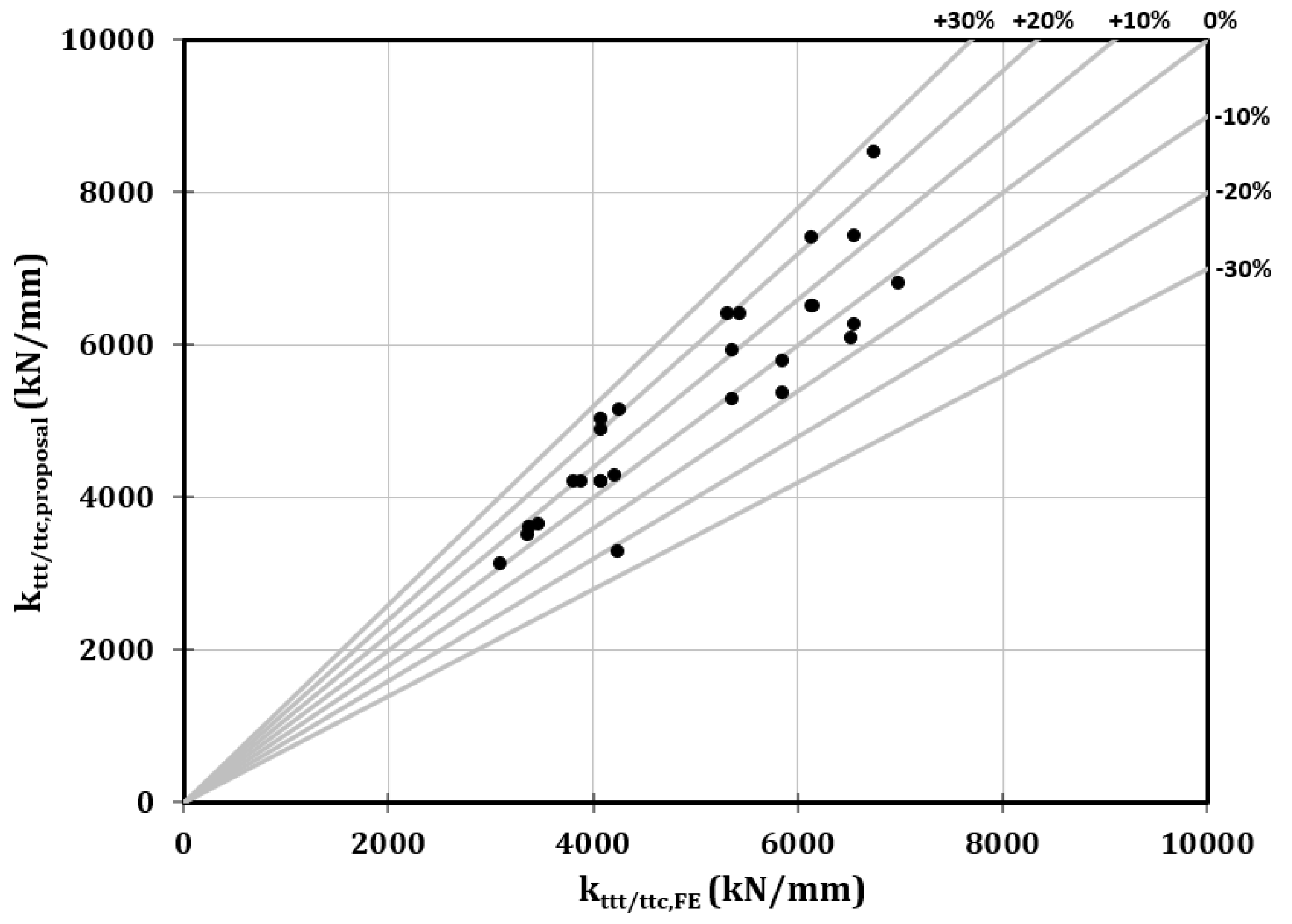
After setting the angle, the outcomes obtained by applying Equation (11) to the analysis of 27 cases are presented in Figure 9 and Table 4.

Figure 9.
Validation of the proposed stiffness formulation: comparison among the FE results and the analytical predictions.
Table 4.
Validation of the proposed stiffness formulation.
As previously mentioned, the average of the ratios between the predicted and numerical stiffness values is close to 1. Additionally, Table 4 reveals that both the standard deviation and the coefficient of variation are approximately 10%. In Figure 9, a comparison between the Finite Element (FE) results and analytical predictions is depicted, with these parameters plotted on the x-axis and y-axis, respectively. It is evident from Figure 9 that there are no cases where the deviations exceed 30%. This evidence substantiates the precision of the proposed formulation and marks a significant milestone in the assessment of the behaviour of the ttt/ttc components.
It is important to note that Equation (11) is presented in a straightforward manner, emphasising that the stiffness of the ttt/ttc components is influenced solely by the steel’s elastic modulus, the tube’s thickness, the dimensionless parameter β, and a coefficient equal to 0.9, corresponding to tan42°. This simplified formulation facilitates its practical application and incorporation into design codes.
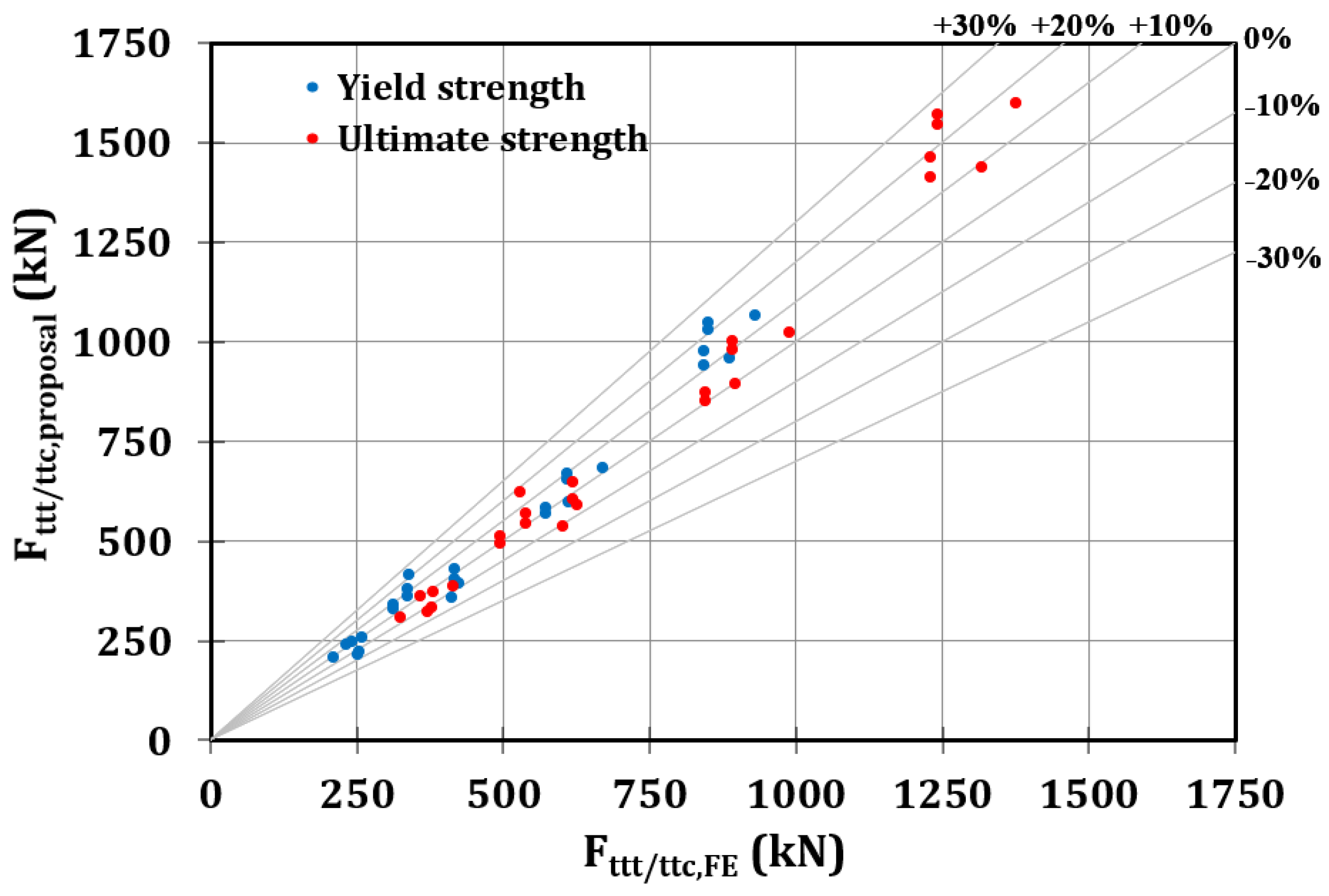
In order to validate the yield strength presented in Equation (10), Table 5 displays the values and the ratios between the yield strength calculated using the derived formulation and the values obtained from numerical simulations. Moreover, considering the observation made in the last paragraph that the ultimate strength is generally 1.5 times the yield strength, Table 5 predicts the ultimate strength based on Equation (12) as follows:
Table 5.
Validation of the proposed strength formulations.
Table 5 demonstrates that the proposed formulations accurately predict both the yield and ultimate strength values from numerical simulations. The mean ratios between analytical and numerical results are 1.04, indicating a high level of accuracy, with coefficients of variation at 0.10. Instead, Figure 10 clearly shows that the discrepancies between numerical and analytical results consistently remain below 30%.
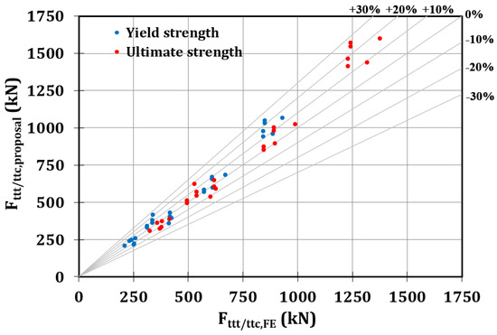
Figure 10.
Validation of the proposed strength formulations: comparison among the FE results and the analytical predictions.
Building upon the understanding of the stiffness and strength of the ttt/ttc components, our forthcoming research endeavours will be focused on consolidating the findings related to all nodal components. This will facilitate the development of a model for predicting the initial stiffness of connections between SHS columns and passing-through IPE beams.
6. Conclusions
The potential of employing connections between Square Hollow Section (SHS) columns and passing-through IPE beams presents an intriguing solution in the construction industry, leveraging the numerous advantages offered by tubular columns. Although advancements such as 3D laser cutting technology (3D-LCT) have enabled the manufacturing of this joint, its widespread adoption is hindered by the absence of design formulations. To fill this knowledge gap, recent research activities at the University of Salerno were devoted to study this connection using the component method approach.
In this context, this manuscript delves into the sources triggered by the rotation of the beam flanges, resulting in local compressive (ttc) and tensile (ttt) forces on the tubular profile.
The key steps and findings of the investigation are summarised as follows:
- -
- By applying principles of elasticity to structural elements, analytical formulations ware developed to predict the initial stiffness and yield strength of the ttt/ttc components.
- -
- The need to validate the derived formulations led to a parametric analysis involving 27 geometrical configurations of Square Hollow Section (SHS) profiles with rectangular holes subjected to displacements along the axis of the hollow profile; the parametric analysis was conducted through numerical simulations using Finite Element software.
- -
- The primary parameters obtained from the numerical simulations included initial stiffness, yield strength, and ultimate strength of the analysed ttt/ttc components; these parameters revealed a consistent relationship between yield and ultimate strength, maintaining a ratio of 1:1.5.
- -
- The stiffness and strength values obtained from the 27 numerical simulations were compared with those derived from the analytical formulations developed in the initial phase of this study; the comparisons demonstrated the effectiveness of the proposed formulations since the average ratio between the analytical predictions and the numerical simulations was approximately 1.00 (with a coefficient of variation of about 10% in relation to the initial stiffness), while the average was approximately 1.04 (with a coefficient of variation of about 10% in relation to the yield and ultimate strength).
Once this phase is completed, the component method approach can be applied to predict the flexural behaviour of connections between SHS columns and passing-through IPE beams.
Author Contributions
Conceptualisation, A.B.F., M.L. and G.R.; methodology, S.D.B., A.B.F., M.L. and G.R.; software, G.E. and S.D.B.; validation, G.E. and S.D.B.; formal analysis, G.E., S.D.B. and M.L.; investigation, G.E., S.D.B. and M.L.; resources, G.E., S.D.B. and M.L.; data curation, G.E. and S.D.B.; writing—original draft preparation, S.D.B.; writing—review and editing, A.B.F., M.L. and G.R.; visualisation, S.D.B.; supervision, M.L., A.B.F. and G.R.; project administration, G.R.; funding acquisition, G.R. All authors have read and agreed to the published version of the manuscript.
Funding
This research received no external funding.
Data Availability Statement
Not available.
Conflicts of Interest
The authors declare no conflict of interest.
References
- Kanakubo, T.; Yonemaru, K.; Fukuyama, H.; Fujisawa, M.; Sonobe, Y. Bond performance of concrete members reinforced with FRP bars. Am. Concr. Inst. ACI Spec. Publ. 1993, 138, 767–788. [Google Scholar]
- Cucuzza, R.; Domaneschi, M.; Camata, G.; Marano, G.C.; Formisano, A.; Brigante, D. FRCM retrofitting techniques for masonry walls: A literature review and some laboratory tests. Procedia Struct. Integr. 2023, 44, 2190–2197. [Google Scholar] [CrossRef]
- Narayanan, P.; Deivanayagam, M. Retrofitting and rehabilitation of masonry structures using FRP composites. Mater. Today Proc. 2023. [Google Scholar] [CrossRef]
- Wu, C.; Ma, G.; Hwang, H.J. Bond performance of spliced GFRP bars in pre-damaged concrete beams retrofitted with CFRP and UHCP. Eng. Struct. 2023, 292, 116523. [Google Scholar] [CrossRef]
- Pall, A.C.; Marsh, C. Response of Friction Damped Braced Frames. J. Struct. Div. 1982, 108, 1313–1323. [Google Scholar] [CrossRef]
- Grigorian, C.E.; Popov, E.P. Energy Dissipation with Slotted Bolted Connections; Earthquake Engineering Research Centre: Berkley, CA, USA, 1994. [Google Scholar]
- Yang, T.S.; Popov, E.P. Experimental and Analytical Studies of Steel Connections and Energy Dissipators; UCB/EERC-95/13; Earthquake Engineering Research Center: Berkley, CA, USA, 1995. [Google Scholar]
- Ricles, J.M.; Sause, R.; Peng, S.W.; Lu, L.W. Experimental evaluation of earthquake resistant posttensioned steel connections. J. Struct. Eng. 2002, 128, 850–859. [Google Scholar] [CrossRef]
- Khoo, H.H.; Clifton, C.; Butterworth, J.; MacRae, G. Experimental study of full-scale self-centring sliding hinge joint connections with friction ring springs. J. Earthq. Eng. 2013, 17, 972–997. [Google Scholar] [CrossRef]
- Latour, M.; Piluso, V.; Rizzano, G. Free from damage beam-to-column joints: Testing and design of DST connections with friction pads. Eng. Struct. 2015, 85, 219–233. [Google Scholar] [CrossRef]
- Freddi, F.; Galasso, C.; Cremen, G.; Dall’Asta, A.; Di Sarno, L.; Giaralis, A.; Gutiérrez-Urzúa, F.; Málaga-Chuquitaype, C.; Mitoulis, S.A.; Petrone, C.; et al. Innovations in earthquake risk reduction for resilience: Recent advances and challenges. Int. J. Disaster Risk Reduct. 2021, 60, 102267. [Google Scholar] [CrossRef]
- Fang, C.; Wang, W.; Qiu, C.; Hu, S.; Macrae, G.A.; Eatherton, M.R. Seismic resilient steel structures: A review of research, practice, challenges and opportunities. J. Constr. Steel Res. 2022, 191, 107172. [Google Scholar] [CrossRef]
- Castiglioni, C.A.; Kanyilmaz, A.; Salvatore, W.; Morelli, F.; Piscini, A.; Hjiaj, M.; Couchaux, M.; Calado, L.; Jorge Proenca Sio, J.; Raso, S.; et al. EU-RFS Project LASTEICON 709807, 2016–2020. Available online: www.lasteicon.eu (accessed on 1 January 2023).
- Makino, Y.; Kurobane, Y.; Paul, J.C.; Orita, Y.; Hiraishi, K. Ultimate capacity of gusset plate-to-tube joints under axial and in plane bending loads. In Proceedings of the 4th International Symposium on Tubular Structues, Delft, The Netherlands, 26–28 June 1991; pp. 424–434. [Google Scholar]
- Makino, Y.; Kurobane, Y.; Ochi, K.; van der Vegte, G.; Wilmshurst, S.R. Database of test and numerical analysis results for unstiffened tubular joints. IIW Doc. 1996, XV-E-96-220. [Google Scholar]
- EN 1993-1-8; Eurocode 3: Design of Steel Structures; Part 1–8: Design of Joints. CEN European Committee for Standardization: Brussels, Belgium, 2005.
- AIJ. Recommendations for the Design and Fabrication of Tubular Truss Structures in Steel; Architectural Institute of Japan: Shiba, Japan, 2002. [Google Scholar]
- Sawada, Y.; Idogaki, S.; Skeia, K. Static and fatigue tests on T-joints stiffened by an internal ring. In Proceedings of the Offshore Technology Conference OTC 3422, Houston, TX, USA, April 1979. [Google Scholar]
- Khador, M.; Chan, T. Cyclic behaviour of external diaphragm joint to CHS column with built-in replaceable links. Steel Constr. 2016, 9, 331–338. [Google Scholar] [CrossRef]
- Li, L.; Wang, W.; Chen, Y.; Lu, Y. Experimental investigation of beam-to-tubular column moment connections under column removal scenario. J. Constr. Steel Res. 2013, 88, 244–255. [Google Scholar] [CrossRef]
- Wang, W.; Chen, Y.; Li, W. Bidirectional seismic performance of steel beam to circular tubular column connections with outer diaphragm. Eartq. Eng. Struct. Dyn. 2011, 40, 1063–1081. [Google Scholar] [CrossRef]
- Zhao, X.L.; Packer, J.A. Tests and design of concrete-filled elliptical hollow section stub columns. Thin-Walled Struct. 2009, 47, 617–628. [Google Scholar] [CrossRef]
- Alostaz, Y.M.; Schneider, S.P. Connections to concrete-filled steel tubes. In Structural Engineering; Series No. 613; University of Illinois at Urbana-Champaign: Champaign, IL, USA, 1996. [Google Scholar]
- Quan, C.; Wang, W.; Zhou, J. Cyclic behavior of stiffened joints between concrete-filled steel tubular column and steel beam with narrow outer diaphragm and partial joint penetration welds. Front. Struct. Civ. Eng. 2016, 10, 333–344. [Google Scholar] [CrossRef]
- Li, X.; Xiao, Y.; Wu, Y.T. Seismic behavior of exterior connections with steel beams bolted to CFT columns. J. Constr. Steel Res. 2009, 65, 1438–1446. [Google Scholar] [CrossRef]
- Voth, A.; Packer, J.A. Branch Plate-to-Circular Hollow Structural Section Connections. I: Experimental Investigation and Finite-Element Modeling. J. Struct. Eng. 2012, 138, 995–1006. [Google Scholar] [CrossRef]
- Kanyilmaz, A.; Castiglioni, C.; Brambilla, G.; Gjoka, K.; Galazzi, A.; Raso, S.; Valli, A.; Brugnolli, M.; Hojda, R. Experimental assessment of tolerances for the fabrication of laser-cut steel joints. Ce/Pap. 2017, 1, 776–785. [Google Scholar] [CrossRef]
- Kanyilmaz, A. The problematic nature of steel hollow section joint fabrication, and a remedy using laser cutting technology: A review of research, applications, opportunities. Eng. Struct. 2019, 183, 1027–1048. [Google Scholar] [CrossRef]
- De Winkel, G.D. The Static Strength of I-Beam to Circular Hollow Section. Ph.D. Thesis, Delft University of Technology, Delft, The Netherlands, 1998. [Google Scholar]
- Voth, A. Branch Plate-to-Circular Hollow Structural Section Connections. Ph.D. Thesis, University of Toronto, Toronto, ON, Canada, 2020. [Google Scholar]
- Das, R.; Castiglioni, C.A.; Couchaux, M.; Hoffmeister, B.; Degee, H. Design and analysis of laser-cut based moment resisting passing-through I-beam-to-CHS column joints. J. Constr. Steel Res. 2020, 169, 106015. [Google Scholar] [CrossRef]
- Couchaux, M.; Vyhlas, V.; Kanyilmaz, A.; Hjiaj, M. Passing-through I-beam-to-CHS column joints made by laser cutting technology: Experimental tests and design model. J. Constr. Steel Res. 2021, 176, 106298. [Google Scholar] [CrossRef]
- Di Benedetto, S.; Latour, M.; Rizzano, G. Chord failure resistance of 3D cut welded connections with CHS columns and through I-BEAMS. Thin-Walled Struct. 2020, 154, 106821. [Google Scholar] [CrossRef]
- Di Benedetto, S.; Latour, M.; Rizzano, G. Assessment of the stiffness of 3D cut welded connections with CHS columns and through I-BEAMS. Structures 2020, 27, 247–258. [Google Scholar] [CrossRef]
- Di Benedetto, S.; Latour, M.; Rizzano, G. Stiffness Prediction of Connections between CHS Tubes and Externally Welded I-Beams: FE Analyses and Analytical Study. Materials 2020, 13, 3030. [Google Scholar] [CrossRef] [PubMed]
- Latour, M.; Di Benedetto, S.; Saldutti, A.; Rizzano, G.; Kanyilmaz, A.; Castiglioni, C.A. Component modelling of 3D laser cut joints with CHS columns and through-all members. Thin-Walled Struct. 2023, 182, 110238. [Google Scholar] [CrossRef]
- Latour, M.; Di Benedetto, S.; Francavilla, A.B.; Saldutti, A.; Rizzano, G. Mechanical Modelling of the Strength and Stiffness of Circular Hollow Section Tube under Localised Transverse Compression and Tension. Materials 2023, 16, 2641. [Google Scholar] [CrossRef]
- Steenhuis, M.; Jaspart, J.P.; Gomes, F.; Leino, T. Application of the component method to steel joints. In Proceedings of the Control of the Semi-Rigid Behaviour of Civil Engineering Structural Connections Conference, Liege, Belgium, 17–19 September 1998. [Google Scholar]
- Tschemmernegg, F.; Rubin, A.; Pavlov, A. Application of the component method to composite joints. In Proceedings of the Control of the Semi-Rigid Behaviour of Civil Engineering Structural Connections Conference, Liege, Belgium, 17–19 September 1998. [Google Scholar]
- Wald, F.; Gresnigt, A.M.; Weynand, K.; Jaspart, J.P. Application of the component method to column bases. In Proceedings of the Control of the Semi-Rigid Behaviour of Civil Engineering Structural Connections Conference, Liege, Belgium, 17–19 September 1998. [Google Scholar]
- da Silva, L.S.; Santiago, A.; Vila Real, P. Application of the Component Method to Steel Joints under Fire Loading; Springer: Berlin/Heidelberg, Germany, 2000. [Google Scholar] [CrossRef]
- Faella, C.; Piluso, V.; Rizzano, G. Structural Steel Semirigid Connections; CRC Press: Boca Raton, FL, USA, 2000. [Google Scholar]
- Sato, A.; Latour, M.; de la Peña, A.; Di Benedetto, S.; Francavilla, A.B.; Rizzano, G. Strength of connections between SHS columns and through plates. Ce/Papers 2023, 6, 1470–1475. [Google Scholar] [CrossRef]
- Abaqus. Analysis User’s Manual Version 6.17; Abaqus Inc.: Palo Alto, CA, USA, 2017. [Google Scholar]
- Faralli, A.C. Large Deformation of T-Stub Connection in Bolted Steel Joints. Ph.D. Thesis, University College of London, London, UK, 2019. [Google Scholar]
- Pavlovic, M.; Markovic, Z.; Veljkovic, M.; Budevac, D. Bolted shear connectors vs. headed studs behaviour in push-out tests. J. Constr. Steel Res. 2013, 88, 134–149. [Google Scholar] [CrossRef]
- EN 1993-1-5; Eurocode 3: Design of Steel Structures; Part 1–5: Piling. CEN European Committee for Standardization: Brussels, Belgium, 2006.

Disclaimer/Publisher’s Note: The statements, opinions and data contained in all publications are solely those of the individual author(s) and contributor(s) and not of MDPI and/or the editor(s). MDPI and/or the editor(s) disclaim responsibility for any injury to people or property resulting from any ideas, methods, instructions or products referred to in the content. |
© 2023 by the authors. Licensee MDPI, Basel, Switzerland. This article is an open access article distributed under the terms and conditions of the Creative Commons Attribution (CC BY) license (https://creativecommons.org/licenses/by/4.0/).