Abstract
Titanium alloys are widely used in various industries. The most common and well-known titanium alloy is titanium alloy with aluminum and vanadium (Ti-6Al-4V). This alloy is used, for example, in the manufacture of aircraft engines. As part of the development of technologies and the emergence of the evolving requirements for materials, Ti-6Al-4V alloys with ultrafine grains less than 1 μm may become promising. This modification of the alloy has excellent strength characteristics, such as increased fatigue resistance. However, manufacturers are aware of the machinability problem of titanium alloys. To date, a sufficiently high level of understanding of this problem has already been achieved. But, there is practically no information about the machinability of ultrafine-grained alloys and their comparison, in this regard, with the usual coarse-grained version. This study presents the results of experimental studies on the influence of cutting parameters (cutting speed, V, m/min; feed rate, Fz, mm/rev) on the roughness and microstructure of the surface of Ti-6Al-4V samples with coarse-grained and ultrafine-grained structures produced via equal-channel angular pressing. It is shown that turning at a low cutting speed (V = 48 m/min) results in a better surface roughness, Ra, for the coarse-grained sample compared to its ultrafine-grained alloy counterpart. When the cutting speed is increased by 1.5 times (up to V = 72 m/min), on the contrary, the ultrafine-grained sample has a lower surface roughness, Ra, compared to the coarse-grained sample. The differences in the morphology and microstructure of the chips, depending on the microstructure type of the processed alloy, are discussed: the presence of plastic flow lines in the chip microstructure of the turned ultrafine-grained sample and the formation of shear bands, cleavages, and microcracks in the chips of the turned coarse-grained alloy.
1. Introduction
Titanium alloys that have a higher specific strength, as compared to heat-resistant steel grades and Ni alloys, are readily usable for various practical applications in modern aircraft engine building. There are heavy-loaded parts (discs, bushes, shafts, blades, etc.) found in power stations, gas compression stations, and aviation equipment, as well as medical devices and implants. As is known, in most cases, parts begin to fail with their surface, which is characterized by parameters such as roughness, residual stresses, waviness, hardening, etc. [1]. The surface quality, in turn, depends on the modes of surface machining. The problems of machining, when producing parts from titanium alloys, are known and are aggravated by the fact that most of these materials, especially in a hardened state, are hard to machine [1,2,3,4]. In particular, low ductility is characterized by a high coefficient of hardening during cutting, approximately twice as high as that of heat-resistant steels and alloys. In addition, the high reactivity of titanium alloys to oxygen, nitrogen, and hydrogen causes the intense embrittlement of the surface layer of alloys due to the diffusion of gas atoms into it when the temperature increases during cutting. The oxidation of the contact layer of chips increases its hardness, contact stresses, and cutting temperature, which enlarges the tool wear rate [2]. Due to the poor thermal conductivity of titanium alloys, heating in the cutting zone causes both the setting of the processed material with the tool material and the appearance of scratches (scabs) on the surface [2].
There are several strategies to improve machinability and, as a result, reduce manufacturing costs. For instance, this can be reached via increasing the efficiency of selecting insert materials, programming the machining center, increasing tool life through improving machining conditions, reducing energy via applying a coolant, etc. [5,6,7,8]. To achieve a higher surface quality of parts, in addition to mechanical cutting, modern methods of processing hard and brittle materials are used, such as precision grinding and electrochemical polishing, ensuring the uniform removal of material while reducing the processing load [9].
Surface roughness is one of the important criteria of surface quality. It is an indicator of the integrity of the processed surface and quantitatively characterizes microscopic roughness [10]. High surface roughness can easily lead to the development of small cracks and stress raisers, which reduces the performance of titanium workpieces. Therefore, it is an important task to control surface roughness when turning or grinding a workpiece. Surface integrity is carefully examined after complex surface treatments of titanium alloys. For example, in [11], a multi-criteria method to optimize process parameters was proposed to reduce surface roughness and improve the material removal rate. In [12], the effect of grinding parameters, such as the cutting speed, feed rate, grinding depth, and abrasive size, on surface integrity was experimentally studied.
It is known that the machinability of titanium alloys is significantly affected by chemical composition, phase distribution, and microstructure, which may be different depending on the mode of thermomechanical processing: equiaxed, lamellar, or duplex [13,14]. In [15], various strategies for high-precision machining on Ti-6Al-4V alloys were considered. In [16], the influence of the microstructure and texture of Ti-6Al-4V, after various annealing conditions and cutting speeds, on cutting forces and residual stresses was investigated. In [17], the microstructural response to cutting forces, the formation of shear zones, and chip morphology during the turning of a Ti-6246 alloy were shown to depend on the conditions of its post-forging heat treatment. The authors of [18] reported on the effect of changing the volume fraction of alpha and beta phases on cutting forces using a Ti-6Al-4V alloy, while the use of a high-pressure coolant provided sufficient lubrication at the cut interface, which reduced the effect of phase transition on the machinability of the titanium alloy Ti-6Al-4V. It was shown in [19,20] that a near-beta Ti-5553 alloy in a heat-treated state has a higher yield strength and fatigue strength but much lower machinability and productivity compared to an alpha + beta Ti-6Al-4V alloy.
In recent decades, much attention has been paid to the study of nanostructured and ultrafine-grained (UFG) metals and alloys processed via severe plastic deformation (SPD) techniques [21,22]. In particular, previously conducted studies have shown that the formation of UFG structures via SPD techniques in Ti-6Al-4V alloys has the potential to increase fatigue resistance, which is attractive for engineering applications of this alloy in high-loaded structures, such as aircraft engines. Ultrafine-grained metals, including UFG titanium alloys, have a significant advantage over coarse-grained ones produced by industry in terms of strength and fatigue resistance [23,24,25]. The authors of [26] reported that the formation of nano or UFG structures in titanium via SPD reduces the adhesive component of the friction coefficient and reduces its tendency to setting [27]. One can assume that the formation of UFG structures in Ti-6Al-4V alloys will result in a positive response to turning conditions. However, there are few publications on studies on the machinability of titanium alloys with UFG structures.
The production of high-load parts from UFG titanium alloys will enlarge the strength, reliability, and fatigue life of the product. Therefore, it is necessary to pay special attention to the choice of turning parameters when producing parts from UFG alloys in order to obtain the required surface quality indicators. In addition, when choosing turning parameters, factors such as the high strength of the UFG workpiece and increased internal residual stresses after SPD should be taken into account. The technological operations to which a material is subjected before turning are important inherent factors that can have a significant impact on the surface quality of the workpiece and the functional properties of the final part [28].
This research is aimed at studying the influence of a formed bulk UFG structure in Ti-6Al-4V workpieces, processed via equal-channel angular pressing, on surface quality. The conditions of the turning process (cutting speed (V, m/min), feed rate (Fz, mm/rev), and cutting depth (t, mm)) of round workpieces of Ti-6Al-4V alloys with coarse-grained and ultrafine-grained structures were studied to assess the response of the material microstructure to surface roughness and integrity.
2. Experimental Procedure and Materials
2.1. ECAP Processing and Sample Size and Shape
Initial bars with coarse-grained (CG) structures and ingots with a UFG structure state were used in the work. The material of this study was Grade 5 Ti-6Al-4V titanium alloy, according to the ASTM B348 standard. It had the following chemical composition: Al—6.6%; V—4.9%; Zr—0.02%; Si—0.033%; Fe—0.18%; C—0.007%; O2—0.17%; N2—0.01%; H2—0.002%; and titanium as the balance. The polymorphic transformation temperature of the alloy was 975 ± 5 °C. To produce a Ti-6Al-4V alloy bar with an ultrafine-grained structure, an initial bar was processed via equal-channel angular pressing (ECAP) in 4 passes. The Bc route (a sequence of 90-degree turns of the workpiece bar) of ECAP processing was applied. The intersection angle between the channels of an ECAP die-set was 120 degrees. Processing was carried out at a temperature of 700 °C [25]. Prior to ECAP, the coarse-grained workpieces with a diameter of 40 mm and a length of 225 mm were subjected to preliminary heat treatment via quenching from a temperature of 950 °C (heating for 20 min) followed by annealing at a temperature of 675 °C for 4 h in order to increase the efficiency of grain refinement in the workpiece.
2.2. Equipment and Cutting Tool for Turning
A screw-cutting lathe with a digital readout (DRA) from JET (model: GH-1640ZX; country of origin: China) was selected for machining. For experimental studies, an ISO holder (PCLNR2525-M16) and an interchangeable polyhedral insert (CNMG 160608-46, Sandvik MKTS, Rostov-on-Don, Russia) were used (Figure 1 and Table 1). It is a double-sided carbide insert, without positive corners, for finishing and semi-finishing in turning (rhombic, with an angle of 80°).
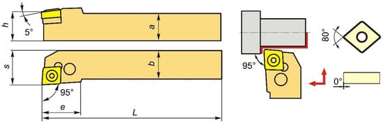
Figure 1.
Holder with interchangeable polyhedral insert.

Table 1.
Technical characteristics of the holder and work insert.
The characteristics of the holder and work insert are presented in Table 1.
Coolant was not used when cutting. The processing conditions were identical for the bars of Ti-6Al-4V alloy with coarse-grained and ultrafine-grained microstructure states.
2.3. Cutting Regimes and Surface Roughness
The CG and UFG workpieces of the Ti-6Al-4V alloy were turned in several zones (like the lateral surface area (LSA) of a cylinder), with lengths ranging from 8 to 10 mm, under various cutting modes, ranging from one to eight. Such LSA zones can be clearly seen in the general view of one of the Ti-6Al-4V alloy workpieces, which is shown in Figure 2. The diameter of the bars was 30 mm, and the length was 200 mm.
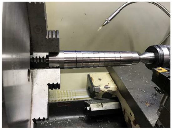
Figure 2.
General view of a Ti-6Al-4V alloy workpiece with different regime zones in the lathe.
The cutting regimes for the Ti-6Al-4V workpieces with CG and UFG structures were selected based on the Sandvik company’s catalog of cutting conditions. The cutting conditions that were selected for the research are listed in Table 2.
Table 2.
Turning regimes of Ti-6Al-4V alloy workpieces with CG and UFG structural states.
The cutting regimes were determined via a combination of the main cutting parameters: speed, depth, and feed rate.
In order to measure the roughness of a surface, a MarSurf PS1 measuring device (Mahr GmbH, Esslingen, Germany) was used, which provides Ra, Rz, and Rmax data. The maximum measurement range was 350 µm (from −200 µm to +150 µm). Surface roughness measurements were carried out over a length of five millimeters. Four measurements were taken on each “zone” in diametrically opposite places and one rotation of 90 degrees. The device used for measurement was a contact device.
2.4. Microstructure, Tensile Properties, and Microhardness
Specimens of Ti-6Al-4V with CG and UFG structures were subjected to mechanical grinding and polishing using silicon suspension for metallographic studies. Then, they were etched with a solution of the following composition: 10HNO3 + 30HF + 60H2O. A microstructure investigation of the samples was carried out using scanning electron microscopy (TESCAN Mira LMS, a.s., Brno, Czech Republic). The phase contrast was observed in back-scattered electron (BSE) mode. An Olympus GX51 light optical microscope with a photomicrographic system (DP71; Olympus, Tokyo, Japan) was used for the chip structure observations.
Tensile tests were performed at room temperature at a rate of one millimeter per minute on an Instron 5982 (Instron, Buckinghamshire, UK) testing machine. The tensile samples had cylindrical gauge sections with initial lengths of 15 mm and a diameter of 3 mm. To ensure the reproducibility of the data, three specimens were tested for each condition.
The microhardness of the polished CG and UFG Ti-6Al-4V alloys was tested via the Vickers method using a DuraJet 10 tester (EMCO-TEST PrufmaSchinen GmbH, Kuchl, Austria). The applied load was 500 g, and the exposure time was 10 s. Microhardness measurements were carried out in the longitudinal axial section of both bars with CG and UFG structures. In each section corresponding to its cutting mode, indenter marks were placed in the region of the bar axis (center) and in the near-surface layer (surface) at a depth of 50 μm.
3. Results
3.1. Microstructure and Tensile Properties of Ti-6Al-4V in the Initial State and after ECAP
Figure 3a displays the microstructure of the CG Ti-6Al-4V alloy in a hot-rolled state. The microstructure is a typical β-transformed structure and consists of packs of α-phase plates (gray-colored) with different crystallographic orientations, depending on the orientation of the initial β grains. The solid interlayers of the residual β phase (white-colored, as shown in Figure 3a) are located in the phase boundaries.
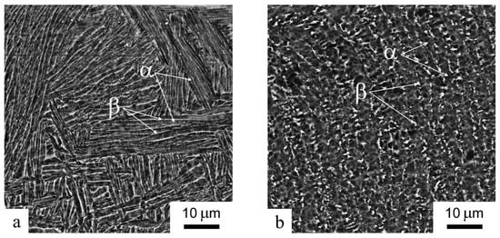
Figure 3.
Microstructure of Ti-6Al-4V alloy billets in the initial state (a) and after ECAP (b). Back-scattered electron mode in scanning electron microscope.
One can observe deformed and distorted plates in the alloy microstructure after equal-channel angular pressing. Equiaxed subgrains are formed inside the plates, and the β phase becomes discontinuous but localized in the shape of individual grains less than 1 μm in size (white-colored, as shown in Figure 3b). Thus, the structure of the alloy after ECAP is a mixture of ultrafine grains and subgrains about 1 μm in size.
The tensile mechanical properties of the Ti-6Al-4V alloy bars with coarse-grained and ultrafine-grained structures are presented in Table 3.
Table 3.
Tensile properties of the Ti-6Al-4V alloy workpieces with CG and UFG structural states.
As we can see, the ECAP treatment leads to a 30% increase in the yield strength of the alloy. However, this is traditionally accompanied by a decrease in elongation, which, in this case, becomes 35% less.
3.2. Surface Roughness after Machining
When processing, according to modes 1–4, at a relatively low cutting speed (V = 48 m/min), one can observe that the workpiece with a CG structure had a lower surface roughness (Ra) compared to the UFG workpiece (Figure 4a). The roughness was 0.446–0.462 µm, on average, and for the UFG billet, it reached 0.795 µm, especially when the feed rate (Fz) was increased from 0.06 to 0.11 mm/rev.
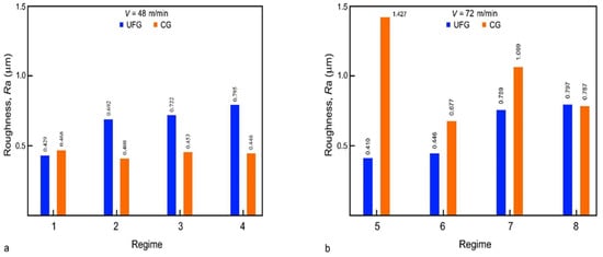
Figure 4.
Surface roughness of CG and UFG Ti-6Al-4V alloys depending on the machining regimes with cutting speeds of (a) V = 48 m/min and (b) V = 72 m/min.
The cutting speed increased to V = 72 m/min and the feed rate, Fz, increased from 0.06 to 0.11 mm/rev, with both leading to growth in the average roughness value of Ra (Figure 4) for the Ti-6Al-4V workpieces with both states. At the same time, the UFG workpiece demonstrated a lower roughness of 0.410–0.446 μm at Fz = 0.06 mm/rev to 0.797 μm at Fz = 0.11 mm/rev compared to the CG alloy, the roughness value of which reached 1.427 μm at Fz = 0.06 mm/rev (Figure 4b). In general, it should be noted that the lowest surface roughness was obtained when turning via mode 5 was applied to the workpiece with the UFG structure (Ra = 0.410 µm) and when the CG structure was subjected to turning according to mode 2 (Ra = 0.408 µm).
3.3. Microhardness and Microstructure of the Surface Layer of Turned Billets
Table 4 lists the average values of the material microhardness in the near-surface layer and billet center depending on the cutting speed for the CG and UFG structures.
Table 4.
The microhardness in the near-surface layer and billet center.
The microhardness values of the Ti-6Al-4V alloy with a UFG structure (HV = 380 MPa) are higher than those in a CG state (HV = 335 MPa). This may be associated with the reduction in the size of structural and phase components after severe plastic deformation via ECAP [25]. Table 4 shows that the average values of microhardness in the center and near-surface layer, regardless of the turning speed and feed rate, are almost the same for both the CG and UFG workpieces, which indicates the absence of any damage and local overheating in the zone in contact with the cutter during turning.
The absence of physical surface damage, microcracks, and the deformation of α plates in both the CG and UFG Ti-6Al-4V alloys, after turning at cutting speeds of 48 and 72 m/min, can be confirmed via the microstructure images of the near-surface area in Figure 5.
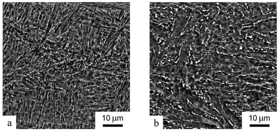
Figure 5.
Microstructure of the near-surface zone of CG (a) and UFG (b) samples at a cutting speed of V = 72 m/min with a feed rate of Fz = 0.11 mm/rev. Back-scattered electron mode in scanning electron microscope.
3.4. Chip Microstructure
Chips obtained from the workpieces with CG and UFG structures through turning via mode 4 (cutting speed V = 48 m/min and feed rate Fz = 0.11 mm/rev) were used in the studies. As a result of turning, a large difference in the surface roughness was achieved (Figure 4). Turning via mode 8 (cutting speed V = 72 m/min and feed rate Fz = 0.11 mm/rev) resulted in a surface roughness value almost the same as the measurement error (see Figure 4). In both cases, the chips had a saw-tooth shape typical of titanium alloys (see Figure 6 and Figure 7).
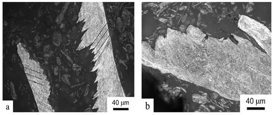
Figure 6.
Chip microstructure of the resulting CG alloy structure when turning at a cutting speed of (a) V = 48 m/min and (b) V = 72 m/min. Light microscope.
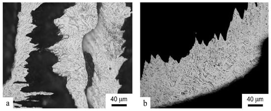
Figure 7.
Chip microstructure of the resulting UFG alloy when turning at a cutting speed of (a) V = 48 m/min and (b) V = 72 m/min. Light microscope.
As is known, as a result of cutting, shear bands with the highest straining are observed in the microstructure of chips [29]. Shear bands are clearly seen in the chips obtained after processing the CG sample at a cutting speed of V = 48 m/min (Figure 6a). Microcracks and cleavages are observed, along with shear bands, in the structure of chips obtained from the CG sample with the cutting speed increased to 72 m/min (Figure 6b). Overall, this indicates that the chips were under very severe friction conditions, especially at higher processing speeds.
On the contrary, there are no distinct shear bands in the microstructure of the chips formed during the turning of the UFG sample (Figure 7). The lines of plastic flow are visible when cutting at both a cutting speed of V = 48 m/min (Figure 7a) and a higher processing speed of V = 72 m/min (Figure 7b). In general, this can be explained via the reduced local cutting force [17].
4. Discussion
This study proved that the microstructure of titanium alloys has a significant effect on the parameters of turning applied to titanium alloys. A reduced grain size in the microstructure of the ECAP samples resulted in enhanced ultimate tensile strength (982 and 1260 MPa for the CG and UFG samples, respectively) and microhardness (335 and 380 HV for the CG and UFG samples, respectively), as shown in Table 2. This has been reported in earlier studies [25,30]. The higher surface microhardness values of the UFG Ti-6Al-4V alloy are due, firstly, to reduced grain sizes in the α and β phases [25]. It has also been shown that the alloy microstructure after ECAP is characterized by a high dislocation density and high internal stresses associated with a heavy distortion of the crystalline lattice, as well as an increase in the proportion of the “harder” α phase after severe plastic deformation via the ECAP method. According to [30], the proportion of the α phase can increase from 85 to 95%. A decrease in the fraction of the metastable β phase can explained by the active βm → α + β transformation induced via SPD processing [25].
In accordance with the theory of ductile fracture, grain refinement in the processed material is accompanied by a decrease in the critical length of a crack. Chip formation, when processing UFG titanium, begins at smaller macrocrack sizes. That is, less work will be required for crack growth under the same stresses. In this case, the local cutting force decreased. In particular, such a tendency was demonstrated for a Ti-6Al-4V alloy with different types of structures (lamellar and duplex) obtained after Beta annealing and STA by the authors in [17]. On the one hand, a harder material leads to losses in cutting forces, for example, for β-transformed lamellar structures. On the other hand, the cutting force is sensitive to the size and morphology of secondary alpha plates, which can cause different material responses to the cutting process. The authors in [17] explain this fact via the mechanism of dislocation glide strain transmission between alpha plates before and until crack initiation (as well as the formation of a chip). It was found that thinner alpha plates result in a lower net force, as they are more easily plastically deformed, possibly due to the reduction in the effective dislocation slip length.
A similar effect is apparently observed in the case of ultrafine grains in the microstructure of the investigated alloy with a UFG structure. When cutting with an increasing temperature in the contact zone, grain boundary dislocation sliding can take place [21], especially when the processing speed is increased (in this work, at V = 72 m/min). This is confirmed via the studies on the morphology of chips that formed during the turning of the workpieces. The traces of plastic flow in the chip of the UFG alloy may be indicative of signs of superplastic deformation in the material, while cleavage and brittle microcracks were observed in the chips of the CG sample, especially when processing was performed at a cutting speed of V = 72 m/min (Figure 6 and Figure 7).
An important result is that the lowest surface roughness of the UFG sample (Ra = 0.401) was achieved at a high machining speed (V = 72 m/min) compared to the CG sample, which exhibited superior roughness at a lower machining speed of V = 48 m/min. The Ra value of the surface of the UFG sample was more than 0.7 µm. With a machining speed of V = 72 m/min applied to the CG sample, a roughness (Ra) value of 1.427 at Fz = 0.06 mm/rev was achieved. Possibly, this can be explained by higher local heating in the contact zone of the cutter with the UFG material at high processing speeds, which contributed to a more plastic flow of the material during turning. In addition, the traces of plastic flow in the chips of the UFG alloy can also be confirmed by previously obtained conclusions about the reduction in the adhesive component of the friction coefficient in UFG titanium. [26].
When the cutting speed increased from 48 to 72 m/min, this led to a slight deterioration in surface roughness in both CG and UFG samples since the cutting speeds were relatively low. For example, in [31], it was shown that the surface roughness of Ti-6Al-4V ELI deteriorated by 50% with an increase in cutting speed from 50 to 200 m/min. The absence of surface damage, microcracks, and the deformation of plates and grains of the α phase (Figure 5) in the near-surface zone of the studied samples may also be associated with the use of relatively low cutting speeds. For example, in [32], at cutting speeds of 100 and 200 m/min, a zone in the near-surface area of a Ti-6Al-4V alloy in which grains underwent strong tensile and rotational straining was observed.
It is known that the final surface quality after turning parts made of titanium alloys is achieved via grinding and polishing, where Ra values can be 0.65 µm and lower [9]. In this work, after turning a UFG workpiece, a minimum roughness (Ra) value of 0.40 μm was achieved at a speed (V) of 72 m/min. It should be noted that in the case of a UFG sample alloy, the best quality of surface roughness is achieved at a higher cutting speed compared to a CG sample, which can improve the productivity of machining and, therefore, has a positive effect on reducing the cost of processing.
5. Conclusions
Thus, the results of this study on the machinability features of a Ti-6Al-4V alloy with coarse-grained and ultrafine-grained structures allow for drawing the following conclusions: Relatively the same surface roughness (Ra = 0.408–0.410 µm) was achieved when processing a CG sample workpiece at a cutting speed of V = 48 m/min, while for a UFG structure alloy, the same was obtained at a higher cutting speed V = 72 m/min, which is a favorable factor for improving the productivity of machining in the case of a UFG alloy. In this case, the feed rate, Fz, increased from 0.06 to 0.11 mm/rev in both cases, leading to an increased surface roughness value. The near-surface zone of the investigated alloys with CG and UFG structures was characterized by the absence of distinct traces of straining of plates and grains of the α phase, as well as signs of local overheating of the material at the studied cutting speeds of 48 and 72 m/min. The chips after turning had a saw-tooth shape, which is typical for titanium alloys. The absence of shear bands and traces of plastic flow in the microstructure of the alloy chips with a UFG structure may point to a decrease in the friction coefficient and cutting force, which is indicative of an improvement in the machinability of titanium alloys, provided that a UFG structure is formed. In this study, we did not consider residual stresses arising during the turning of titanium alloys as a result of local plastic deformation and critical shear when the material is removed from the surface. This is quite important for UFG structures of titanium alloys in terms of developing the method and mode of turning, taking into account high-volume stresses after severe plastic deformation. This requires a detailed study, which will be the subject of our further research.
Author Contributions
Conceptualization, I.S., V.M. and M.P.; supervision, I.S.; methodology, I.S., A.P. and V.M.; investigation, A.P., A.G. and I.K.; writing—original draft preparation, I.S.; writing—review and editing, A.P. and M.P.; visualization, A.P. All authors have read and agreed to the published version of the manuscript.
Funding
The study was funded by the Russian Science Foundation (grant number 21-79-10167; https://rscf.ru/project/21-79-10167/ (accessed on 5 October 2023)).
Data Availability Statement
Data can be made available upon request.
Conflicts of Interest
The authors declare no conflict of interest.
References
- Bran, D.T.; Elefterie, C.F.; Ghiban, B. Aeronautical Industry Requirements for Titanium Alloys. IOP Conf. Ser. Mater. Sci. Eng. 2017, 209, 012059. [Google Scholar] [CrossRef]
- Siregar, I.; Saedon, J.B.; Adenan, M.S.; Nor, N.M.; Azmi, M.F.M.; Jamaludin, M.H.B. Tool wear investigation in drilling titanium alloy. IOP Conf. Ser. Mater. Sci. Eng. 2019, 505, 012043. [Google Scholar] [CrossRef]
- Astakhov, V.P. The assessment of cutting tool wear. Int. J. Mach. Tools Manuf. 2004, 44, 637–647. [Google Scholar] [CrossRef]
- Patil, A.S.; Ingle, S.V.; More, Y.S.; Nathe, M.S. Machining Challenges in Ti-6Al-4V.-A Review. Int. J. Innov. Eng. Technol. 2015, 5, 6–23. [Google Scholar]
- Sun, S.; Brandt, M.; Dargusch, M.S. Thermally enhanced machining of hard-to-machine materials—A review. Int. J. Mach. Tools Manuf. 2010, 50, 663–680. [Google Scholar] [CrossRef]
- Rahman, M.; Wang, Z.-G.; Wong, Y.-S. A Review on High-Speed Machining of Titanium Alloys. JSME Int. J. Ser. C 2006, 49, 11–20. [Google Scholar] [CrossRef]
- Tascioglu, E.; Gharibi, A.; Kaynak, Y. High Speed Machining of Near-beta Titanium Ti-5553 Alloy Under Various Cooling and Lubrication Conditions. Int. J. Adv. Manuf. Technol. 2019, 102, 4257–4271. [Google Scholar] [CrossRef]
- Dargusch, M.S.; Sivarupan, T.; Bermingham, M.; Rizwan, A.R.R.; Palanisamy, S.; Sun, S. Challenges in laser-assisted milling of titanium alloys. Int. J. Extrem. Manuf. 2021, 3, 015001. [Google Scholar] [CrossRef]
- Guo, J.; Goh, M.H.; Wang, P.; Huang, R.; Lee, X.; Wang, B.; Nai, S.M.L.; Wei, J. Investigation on surface integrity of electron beam melted Ti-6Al-4 V by precision grinding and electropolishing. Chin. J. Aeronaut. 2020, 34, 28–38. [Google Scholar] [CrossRef]
- Jiang, G.; Yang, H.; Xiao, G.; Zhao, Z.; Wu, Y. Titanium alloys surface integrity of belt grinding considering different machining trajectory direction. Front. Mater. 2022, 9, 1052523. [Google Scholar] [CrossRef]
- Guo, J.; Shi, Y.Y.; Chen, Z.; Yu, T.; Zhao, P.; Shirinzadeh, B. Optimal parameter selection in robotic belt polishing for aeroengine blade based on GRARSM method. Symmetry 2019, 11, 1526. [Google Scholar] [CrossRef]
- Tao, Z.; Yaoyao, S.; Laakso, S.; Zhou, J.M. Investigation of the effect of grinding parameters on surface quality in grinding of TC4 titanium alloy. Procedia Manuf. 2017, 11, 2131–2138. [Google Scholar] [CrossRef]
- Lutjering, G.; Williams, J.C. Titanium; Springer: Berlin/Heidelberg, Germany, 2007. [Google Scholar]
- Veiga, C.; Davim, J.P.; Loureiro, A.J.R. Properties and applications of titanium alloys: A brief review. Rev. Adv. Mater. Sci. 2012, 32, 133–148. [Google Scholar]
- Denkena, B.; Grove, T. The Effect of Microstructure on the Machinability of Ti-6Al-4V. In Proceedings of the 13th World Conference on Titanium, San Diego, CA, USA, 16–20 August 2015; pp. 905–910. [Google Scholar] [CrossRef]
- Telrandhe, S.V.; Saxena, A.K.; Mishra, S. Effect of microstructure and cutting speed on machining behavior of Ti6Al4V alloy. J. Mech. Sci. Technol. 2017, 31, 2177–2184. [Google Scholar] [CrossRef]
- Suárez Fernández, D.; Wynne, B.P.; Crawforth, P.; Jackson, M. Titanium alloy microstructure fingerprint plots from in-process machining. Mater. Sci. Eng. A 2021, 811, 141074. [Google Scholar] [CrossRef]
- Patil, S.; Kekade, S.; Phapale, K.; Jadhav, S.; Powar, A.; Supare, A.; Singh, R. Effect of α and β Phase Volume Fraction on Machining Characteristics of Titanium Alloy Ti6Al4V. Procedia Manuf. 2016, 6, 63–70. [Google Scholar] [CrossRef][Green Version]
- Arrazolaa, P.-J.; Garay, A.; Iriarte, L.-M.; Armendia, M.; Maryab, S.; Le Maîtrec, F. Machinability of titanium alloys (Ti6Al4V and Ti555.3). J. Mater. Process. Technol. 2009, 209, 2223–2230. [Google Scholar] [CrossRef]
- Suárez Fernández, D.; Jackson, M.; Crawforth, P.; Fox, K.; Wynne, B.P. Using machining force feedback to quantify grain size in beta titanium. Materialia 2020, 13, 100856. [Google Scholar] [CrossRef]
- Valiev, R.Z.; Zhilyaev, A.P.; Langdon, T.G. Bulk Nanostructured Materials: Fundamentals and Applications; Wiley/TMS: Hoboken, NJ, USA, 2014. [Google Scholar]
- Valiev, R.Z.; Estrin, Y.; Horita, Z.; Langdon, T.G.; Zehetbauer, M.J.; Zhu, Y. Producing Bulk Ultrafine-Grained Materials by Severe Plastic Deformation: Ten Years Later. JOM 2016, 68, 1216–1226. [Google Scholar] [CrossRef]
- Zherebtsov, S.; Semenova, I.P.; Halina, G.; Motyka, M. Advanced mechanical properties. In Nanocrystiline Titanium; Garbacz, H., Semenova, I., Eds.; Elsevier Inc.: Amsterdam, The Netherlands, 2019; pp. 103–121. [Google Scholar]
- Zherebtsov, S.V. Strength and ductility-related properties of ultrafine grained two-phase titanium alloy produced by warm multiaxial forging. Mater. Sci. Eng. A 2012, 536, 190–196. [Google Scholar] [CrossRef]
- Semenova, I.P.; Polyakova, V.V.; Dyakonov, G.S.; Polyakov, A.V. Ultrafine-Grained Titanium-Based Alloys: Structure and Service Properties for Engineering Applications. Adv. Eng. Mater. 2019, 22, 1900651. [Google Scholar] [CrossRef]
- Zhu, Y.T.; Stolyarov, V.V.; Shuster, L.S.; Migranov, M.S.; Valiev, R.Z. Reduction of friction coefficient of ultrafine-grained CP titanium. Mater. Sci. Eng. A 2004, 371, 313–317. [Google Scholar] [CrossRef]
- Shuster, L.S.; Migranov, M.S.; Chertovskikh, S.V.; Sadykova, A.Y. Triboengineering Characteristics of Ultra-Fine Granularly Structured Titanium Produced by Intensive Plastic Deformation. Frict. Wear 2005, 26, 208–214. [Google Scholar]
- Zmarzły, P. Technological Heredity of the Turning Process. Teh. Vjesn. 2020, 27, 1194–1203. [Google Scholar] [CrossRef]
- Kent, D.; Rahman Rashid, R.; Bermingham, M.; Attar, H.; Sun, S.; Dargusch, M. Insights into Machining of a β Titanium Biomedical Alloy from Chip Microstructures. Metals 2018, 8, 710. [Google Scholar] [CrossRef]
- Semenova, I.P.; Saitova, L.R.; Dotsenko, T.V.; Kil’mametov, A.R.; Valiev, R.Z.; Islamgaliev, R.K.; Demakov, S.L. Evolution of the structure of the VT6 alloy subjected to equal-channel angular pressing. Phys. Met. Metallogr. 2005, 100, 66–72. [Google Scholar]
- Harun, S.; Burhanuddin, Y.; Ibrahim, G.A. The Effect of Cutting Parameters on Surface Roughness and Morphology of Ti-6Al-4V ELI Titanium Alloy during Turning with Actively Driven Rotary Tools. J. Manuf. Mater. Process. 2022, 6, 105. [Google Scholar] [CrossRef]
- Edkins, K.D.; van Rensburg, N.J.; Laubscher, R.F. Evaluating the Subsurface Microstructure of Machined Ti-6Al-4V. Procedia CIRP 2014, 13, 270–275. [Google Scholar] [CrossRef]
Disclaimer/Publisher’s Note: The statements, opinions and data contained in all publications are solely those of the individual author(s) and contributor(s) and not of MDPI and/or the editor(s). MDPI and/or the editor(s) disclaim responsibility for any injury to people or property resulting from any ideas, methods, instructions or products referred to in the content. |
© 2023 by the authors. Licensee MDPI, Basel, Switzerland. This article is an open access article distributed under the terms and conditions of the Creative Commons Attribution (CC BY) license (https://creativecommons.org/licenses/by/4.0/).