Article

The Effect of Water Jet Overlaps in a Descaler on the Quality of Surface of the Hot Rolled Steel

Faculty of Mechanical Engineering, Brno University of Technology, 61669 Brno, Czech Republic
*
Author to whom correspondence should be addressed.
Metals 2023, 13(10), 1722; https://doi.org/10.3390/met13101722
Submission received: 25 August 2023 / Revised: 2 October 2023 / Accepted: 6 October 2023 / Published: 10 October 2023
(This article belongs to the Section Metal Casting, Forming and Heat Treatment)

Abstract

:
Hot rolling is a highly efficient steel processing method involving the heating and subsequent rolling of semi-finished cast products within mills; however, heating results in the formation of an undesirable, inhomogeneous oxide layer on the surface. Removal of this layer, known as scales, prior to rolling is essential to prevent scales from being rolled into the surface. The scales are removed in the descaler. Most descalers use multiple high-pressure hydraulic descaling nozzles with overlapping sprays. This setting can cause excessive cooling in the overlap area, uneven descaling of the surface, and the presence of residual scales. It can also result in uneven cooling at the finishing line. This study illustrates a typical nozzle configuration commonly used in industrial plants in the hydraulic descaling process and compares its results with a new configuration. The research focuses on examining the overlap area and the washout area of the sprays. The goal is to address the inhomogeneous descaling problem and propose procedures to prevent residual scales. It was shown that one of the problematic areas is the washout area, where the average thickness of the remaining scales was more than four times higher than other descaling areas. Reducing the offset angle has proven to be a good way to eliminate the washout area and achieve a homogeneous descaling process.

1. Introduction

Hot rolling is a very productive method of steel processing today. A semi-finished cast product (slab, bloom, or ingot) is heated and fed into the rolling mill. During heating, an unwanted oxide layer is formed on the surface. The oxide layer is inhomogeneous and consists of three main components, wüstite, hematite, and magnetite, with many voids in between [1]. Determining the physical properties of this locally porous structure is difficult [1,2,3,4,5]. This layer of scales must be removed prior to rolling; otherwise, the scales will be rolled into the surface (creating an uncomplying product) and cause significant wear on the mill rolls. Nowadays, mid and high Si (silicon) steels have become more popular due to a good ratio between mechanical properties and price. However, these steel grades are difficult to descale due to the presence of an adherent fayalite phase [6]. Many other recent papers also focus on Si-containing steel due to this fact [7,8,9,10]. Even low Si steels can contain 16–20% Si in the as-cast surface layer [11].
The scales are removed in the descaler. The majority of the descalers use high-pressure hydraulic descaling [8,11,12]. The descaler typically consists of one or two rows of high-pressure nozzles. The descaling spray creates a water knife that removes the scales from the surface and reduces the surface temperature. According to [13], the affected layer is estimated to be 12 mm. Article [13] also states that in hot rolling processes, the spray significantly affects dislocation density and has a moderate effect on recrystallization and grain size refinement.
Since one nozzle cannot effectively cover the entire width of the steel strip, multiple nozzles with overlapping sprays must be used. The overlap area is often overcooled [14]. This setting can result in uneven descaling of the surface and residual scales. However, most papers present results with a single nozzle test [6,7,11,15,16] or without considering the interaction between multiple jets [8]. Research at the Brno University of Technology also focuses on the interaction between multiple water jets using various types of experiments such as impact pressure distribution measurement, erosion test, hot descaling test, and heat transfer measurement because the interaction area was found to be critical for the quality of descaling [17].
The residual scales are usually unevenly distributed on the rolled plate and can affect the wear of the work roll both mechanically and thermally [18]. They drastically reduce the heat transfer coefficient. This leads to uneven cooling at the finishing line. The scales also suppress radiation emissions, and the pyrometer on the hot-rolling line measures a lower temperature than the actual one. This can lead to incorrect evaluation of the rolling process and incorrect intervention [19]. Also, a bright band (alternatively bright trace or ridge) is a common phenomenon that can appear on the surface of a hot-rolled strip [20].
Much work has been done in the field of mathematical modeling of single droplets [21,22] and metal forming [23]. The studies of high-pressure (high-velocity) water jets have shown that the assumption of single droplets is typically far from reality and that the jet consists of water clusters or bunches [15,24]. As presented in [25], using scanning electron microscopy, water droplets cause erosion differently from erosion caused by water clusters or bunches. The modeling of descaling still relies on precisely determined boundary conditions because the process is very fast, and there are many variables that can affect the interactions on the surface [26]. Therefore, experimental work is crucial for optimizing the process itself and irreplaceable for verification.
This article illustrates a typical configuration commonly used in industrial plants in the hydraulic descaling process and compares its results with a new configuration. The work focuses on the overlap area and the washout area of the sprays. This study draws on research carried out in previous years in our department and presented in papers [14,27]. At the end of the article, procedures for preventing residual scales are proposed.
This study attempts to address the problem of inhomogeneous descaling and ridge formation on the surface.

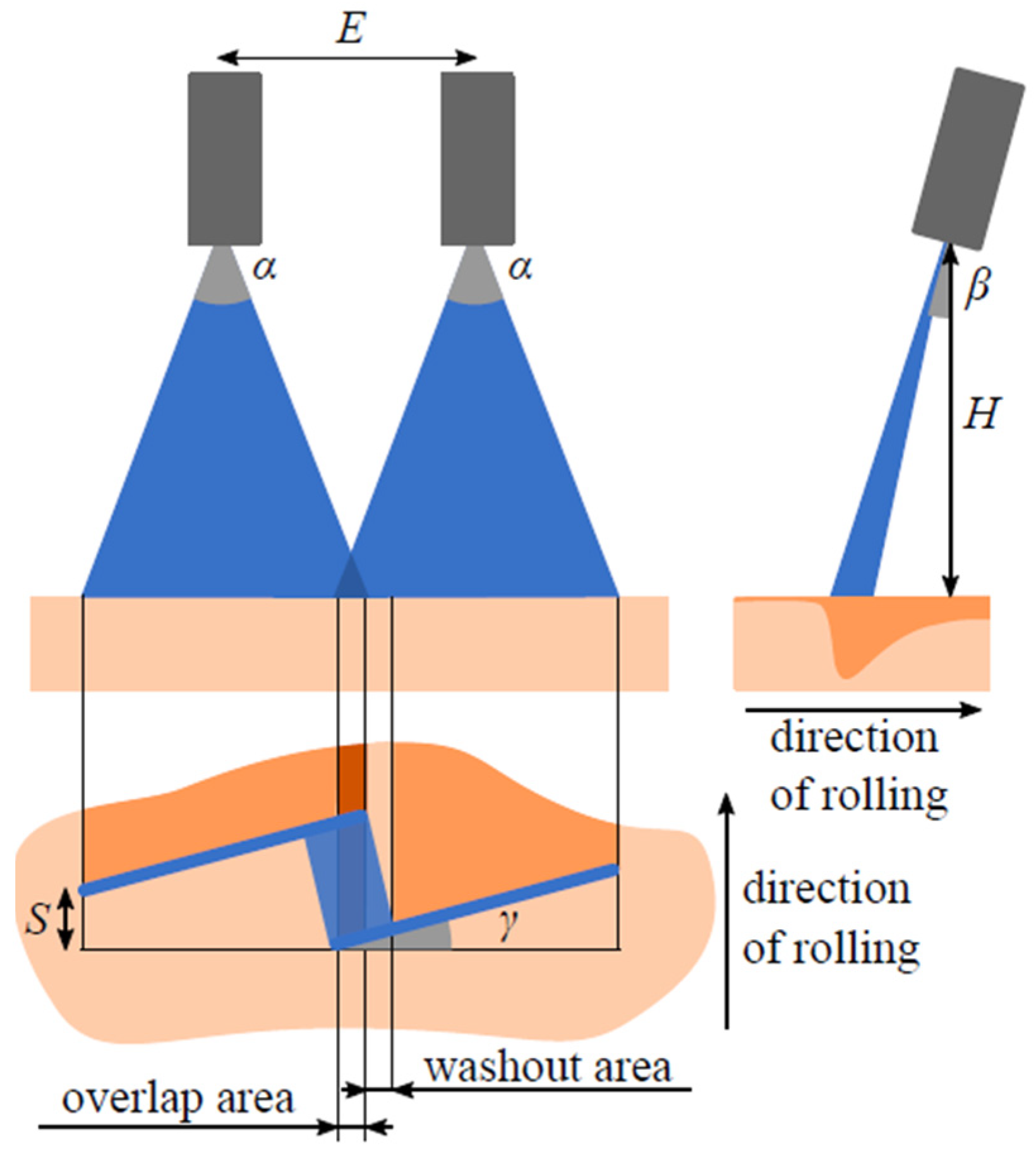
2. Nozzle Configuration

Each nozzle is characterized by its spray angle α (see Figure 1), and flow rate Q. The mutual position of the nozzles can be described by several parameters: pitch E, height from the surface H, inclination angle β, and offset angle γ.
In order to descale the entire width of the steel strip, the nozzles have to overlap in a so-called overlap area (see Figure 1). The overlap area is covered by both sprays, resulting in a greater cooling impulse on the surface in this area. The overlap area for configurations with a non-zero offset angle causes a reduction in the impact pressure on the left side of the right jet. This area is called the washout (see Figure 1).
An additional parameter called spray spot distance S was added for the purpose of the research. This parameter determines the distance between the nozzles in the rolling direction. Under operating conditions, this distance is set to zero, and the nozzles are lined up. A positive value of the spray spot distance increases the washout of the right nozzle, creates a smoother pressure reduction in this area, and can simulate a wide range of conditions for spray angles α.
Complete information of all four presented nozzle configurations are summarized in Table 1. The most important settings are commented on in the following paragraph. The feed water pressure of 40 MPa was chosen because it is used in the production line to descale steels with higher silicon content.

2.1. First and Second Configuration

Configurations C1 and C2 simulated a very wide washout area with a smooth pressure reduction. The configurations have an offset angle of 15°, which is also commonly used in the industry [28,29].
The spray spot distance of C1 was set to 10 mm, which increased the calculated washout area to 25.2 mm in width. The calculated overlap area was 4.3 mm wide. The spray spot distance of C2 was 0 mm. The corresponding calculated overlap area was 2.6 mm wide, and the calculated washout area was 17.9 mm wide. Configurations C1 and C2 are chosen to analyze descaling in the potentially problematic washout and overlap areas.

2.2. Third and Fourth Configuration
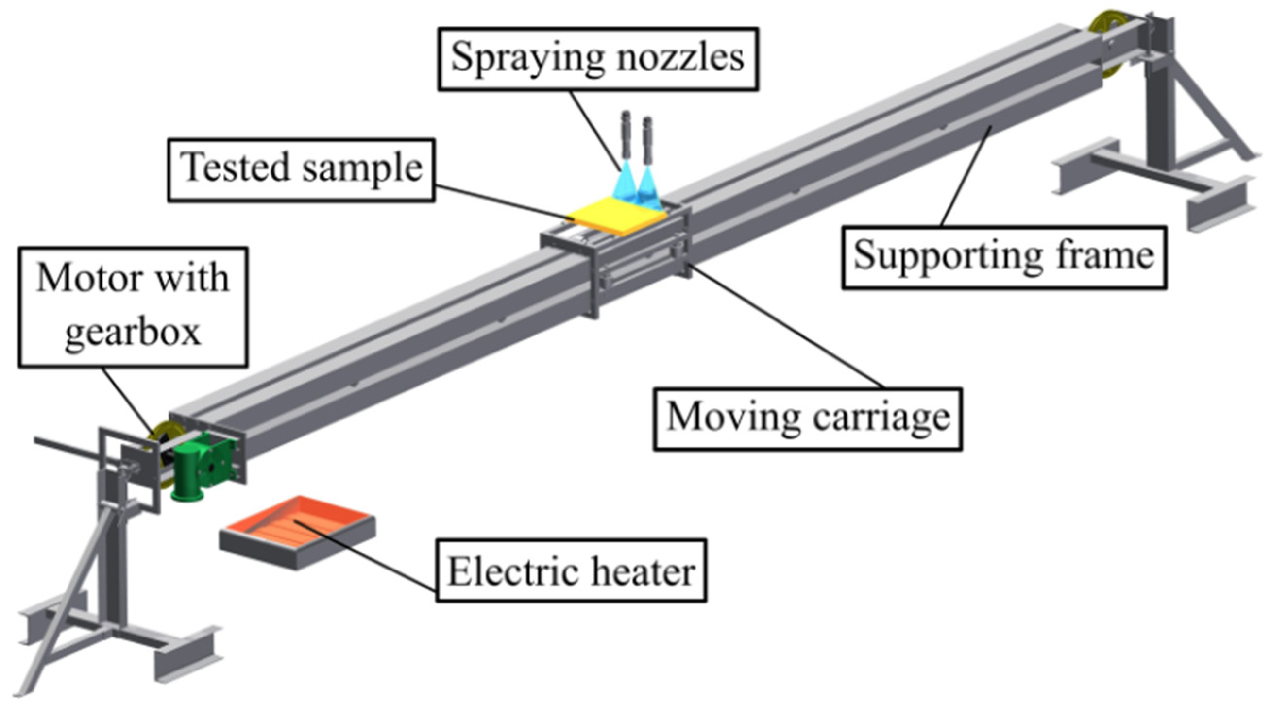
Configurations C3 and C4 simulated a narrow washout area. The offset angle of C3 was set to 0°. The calculated overlap area was 6 mm wide. There was no washout area, and the water jets collided above the steel surface. The offset angle of C4 was set to 3°. The calculated overlap area was 5.7 mm wide. The calculated washout area was 5.5 mm wide. A configuration of nozzles with zero offset angle and its consequences on surface cooling has already been introduced in [14,27]. Configuration C3 was selected to minimize the washout area and configuration C4 tested a case when the alignment of the water jets is not perfect, as is common in production lines.

3. Experiments

The descaling process can be studied via several experimental methods. Mainly via impact pressure distribution measurements, erosion measurements, heat transfer coefficient measurements, and hot descaling tests that simulate the actual operating conditions for a specific type of steel. All of these experiments are performed in the heat transfer and fluid flow laboratory, and each nozzle configuration can be tested for mechanical and thermal effects on the particular steel.

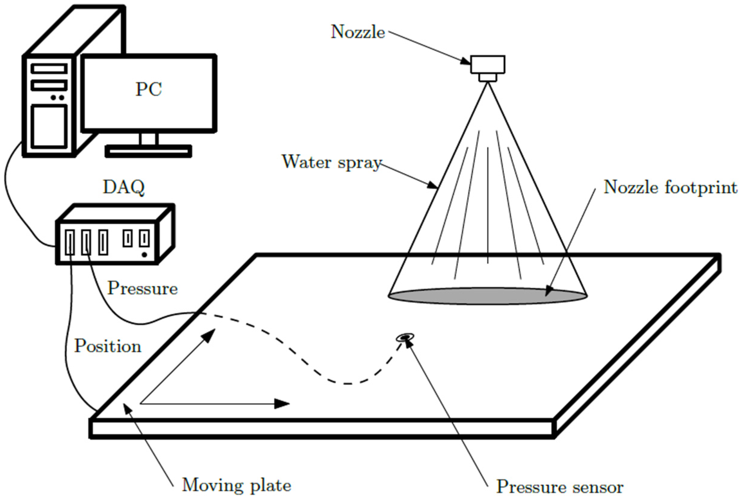
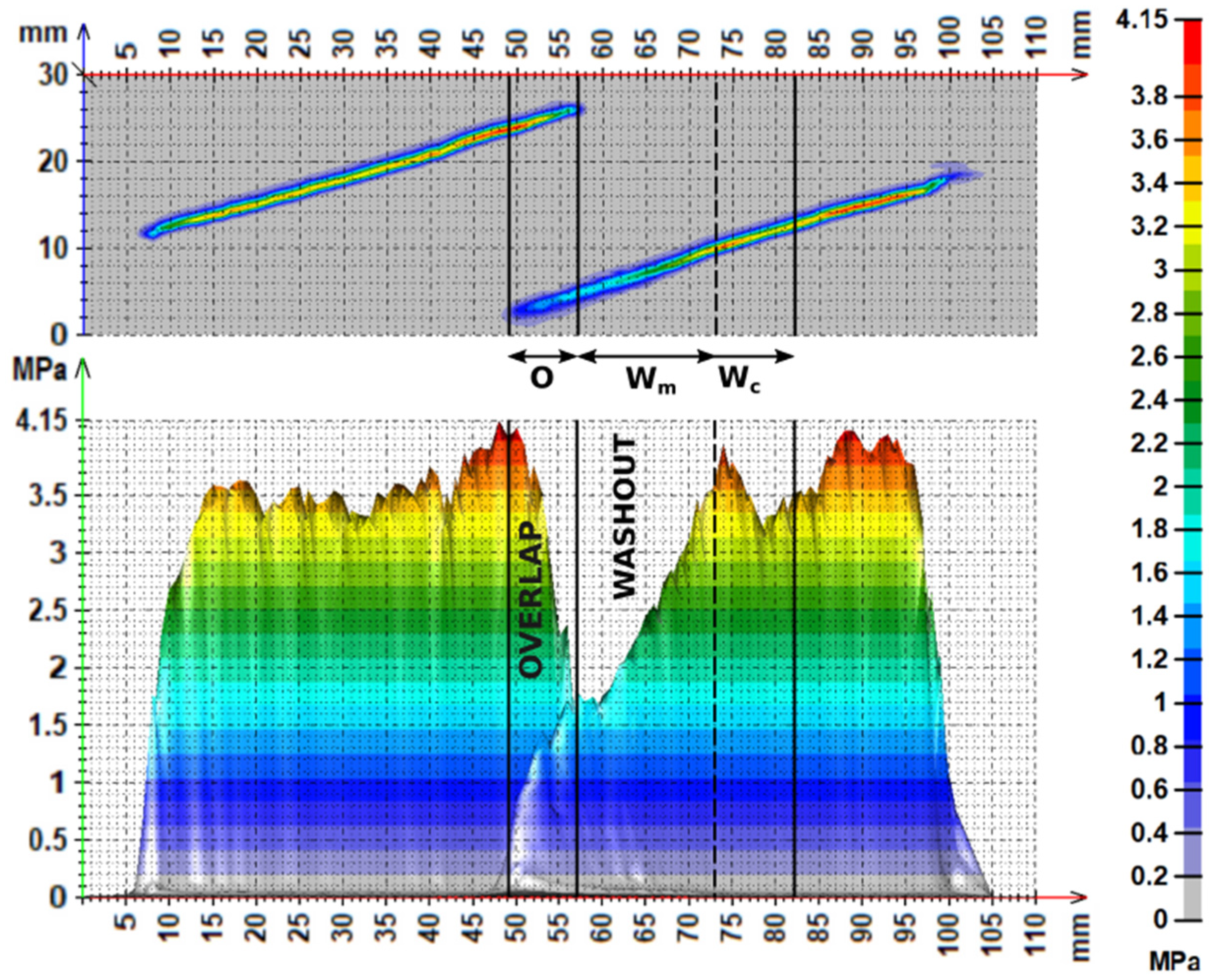
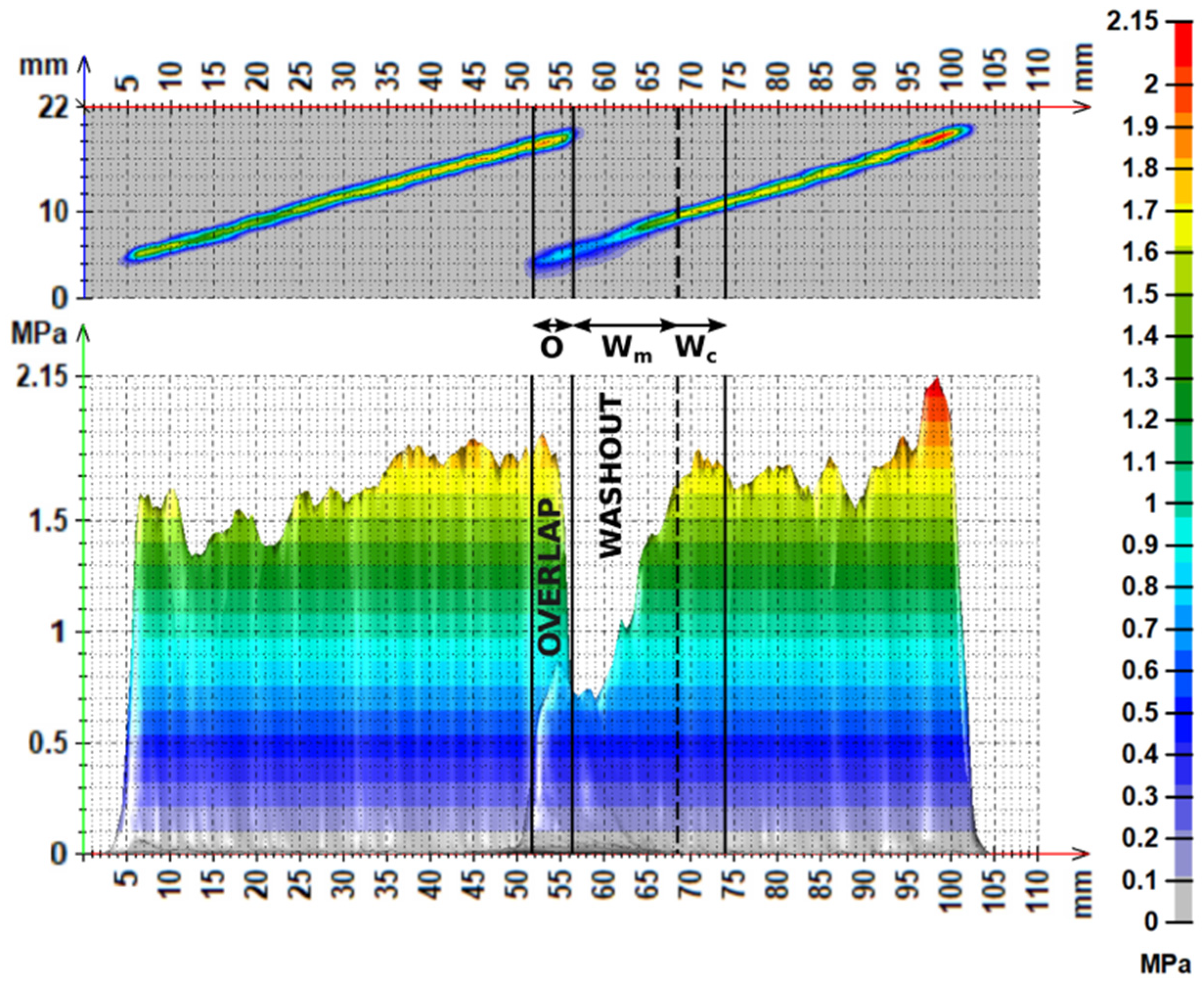
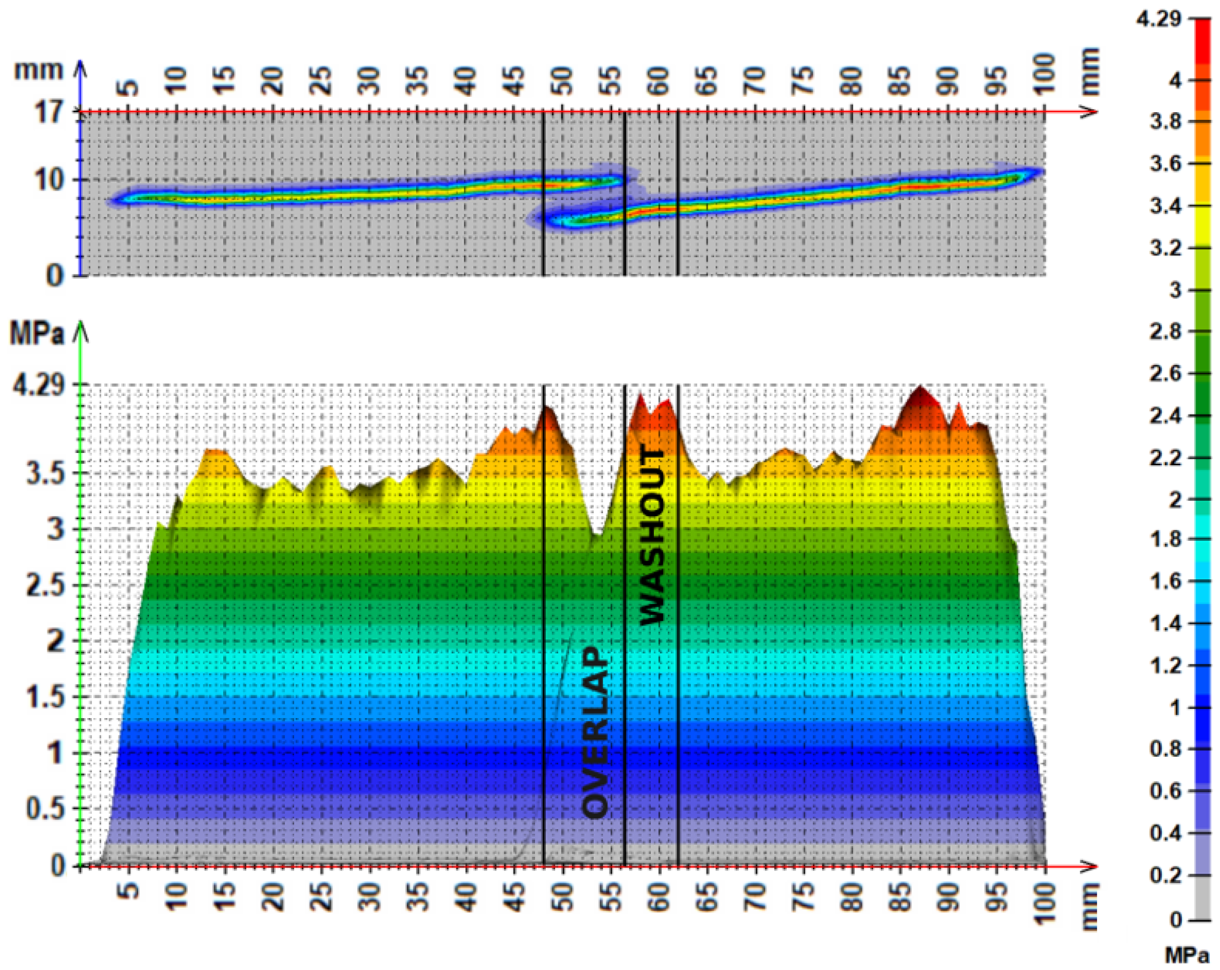
3.1. Impact Pressure Distribution Measurement

The impact pressure distribution measurement examines the pressure distribution on the surface of the steel. The nozzles spray onto a moving steel plate equipped with a pressure sensor (see Figure 2). The pressure sensor DMP 333 from BD SENSORS with a nominal pressure range of 0–100 bar was used. The movement of the plate is controlled by a computer so that the entire investigated area is scanned by the pressure sensor with a diameter of 0.2 mm. A matrix of position-dependent values is recorded on the computer and displayed as a three-dimensional graph. Important spray characteristics (such as spray width, spray depth, homogeneity of distribution along the spray width, and maximum value) are calculated.

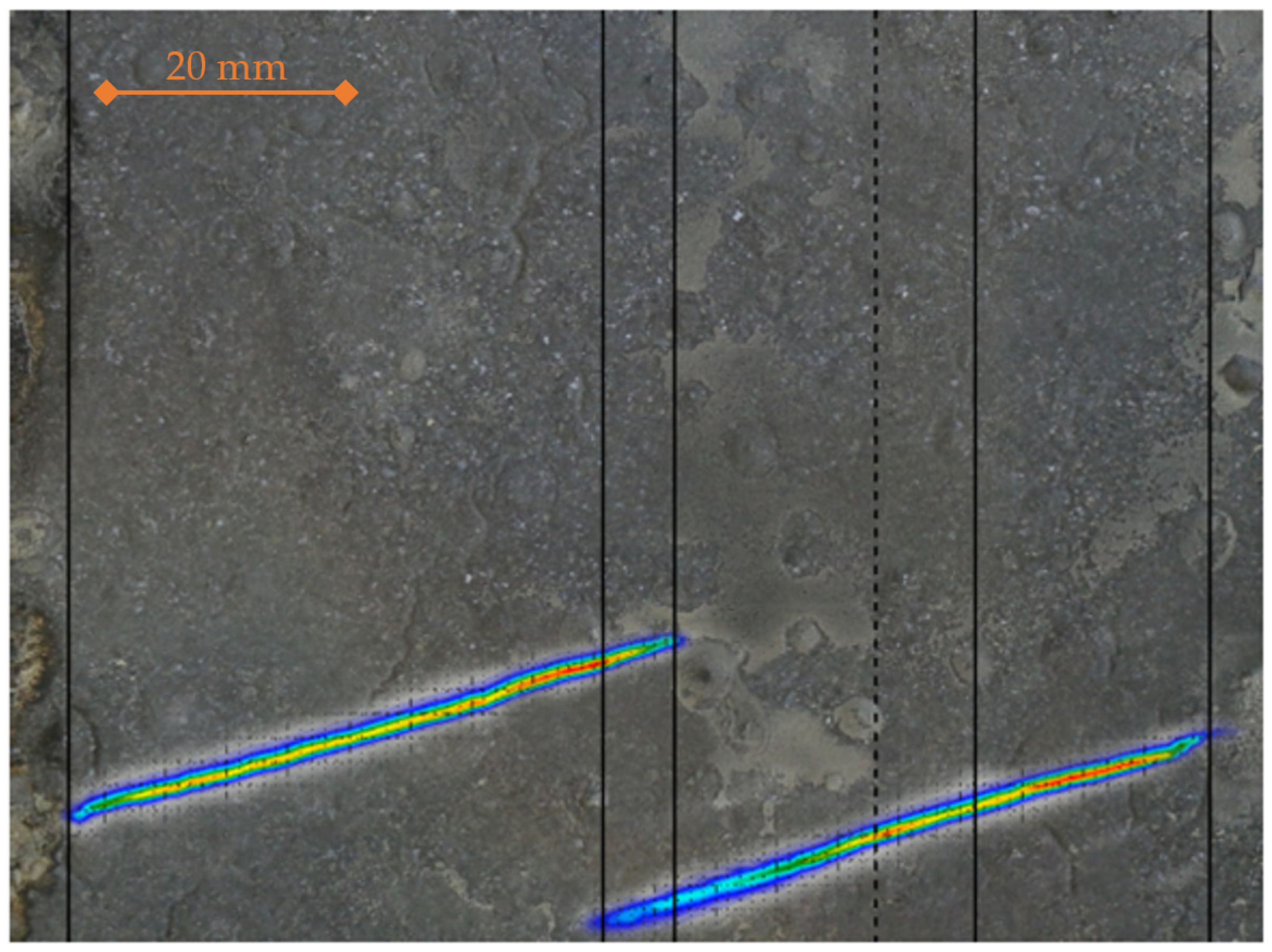
3.2. Hot Descaling Tests

Hot descaling tests evaluate the quality of descaling for a given nozzle configuration and steel type at a specific temperature. The procedure for a given steel is set experimentally, and the nozzle configuration is chosen so that part of the scales remains on the surface and part is descaled. This is performed to demonstrate the different behavior of scales under different descaling conditions.
Before the experiment, the surface of the test plate was ground to a clean steel surface without using abrasive fluids. The experimental procedure starts in the electric furnace, where the test plate is heated to the initial temperature. The dimensions of the test plate were 250 mm × 200 mm × 40 mm. The surface is exposed to the atmosphere in the furnace and oxidized for the required time. The surface temperature of the test plate is measured by a thermocouple attached to the surface, and the temperature history is recorded during the oxidation process. The plate is removed from the furnace and placed on the moving carriage of the linear test bench (Figure 3). The carriage is moved through the descaling section and then immediately cooled in a protective atmosphere to prevent further scale formation on the surface. After cooling down, the descaled surface is documented, and the remaining scale thickness is measured with a dual-scope instrument and, if necessary, analyzed under a microscope.

4. Results

4.1. Configuration C1

The impact pressure distribution of the C1 configuration is shown in Figure 4. The measured overlap area O was approximately 8 mm wide. The width of the washout area Wc in the figure derived from the theoretical calculation was 25.2 mm. The parameter Wm was defined as the width of the measured washout area because the impact pressure measurements showed an uneven distribution of the impact pressure of each nozzle. The width of Wm was defined as the section from the overlap area to the point where the pressure was equivalent to the average maximum pressure of the left unaffected nozzle. The width of Wm was 16 mm. The average maximum impact pressure was 3.47 MPa for the left nozzle, 3.65 MPa for the right nozzle in the unaffected area, 3.12 MPa in the washout area, and 1.47 MPa in the overlap area. The impact pressure of the right nozzle was reduced by more than half in the overlap area. The impact pressure distribution shows a slightly increasing trend of the maximum impact pressure in the width direction, caused by the positive offset angle of 15° and the inclination angle of 15° (different nozzle–surface distance on the ends of the nozzle footprint).
Configuration C1 was then used on dual-phase steel 1.0936 (HDT580X), see Figure 5. The furnace was preheated up to 1240 °C, slightly above the heating temperature, to eliminate heat loss during sample insertion into the furnace. The heating time was 120 min, and the final heating temperature was 1200 °C before descaling.
The surface of the sample was mostly descaled along the width with the exception of the washout area in the width of Wm, where significantly thicker scales remained on the surface.
After the experiment, the sample was cut in half, and small specimens were taken for further analysis. The specimens covered the washout area, the overlap area, and the “single nozzle area” (the section under the left nozzle, unaffected area by the right nozzle). The surfaces of the specimens were examined under a microscope, and the photographs were analyzed using an adaptive thresholding algorithm. The height and structure of the scales in the overlap and washout areas are shown in Figure 6. The results of the analysis are shown in Figure 7. The original layer of scales was up to 185 μm; the average value was 132 μm. The original layer was reduced in several regions because the scales were easy to peel off, and they dropped out during the experiment. The reduced, original layer had an average height of 38 μm. The remaining scales in the washout area had an average thickness of 43 μm. The remaining scales in the overlap area had an average thickness of 12 μm. In the single nozzle area, the average thickness of the remaining scales was 11 μm, which was nearly the same as in the case of the overlap area. These findings showed that the most problematic area is the washout area, where the average thickness of residual scales was more than three times higher compared to the single nozzle area.

4.2. Configuration C2

The impact pressure distribution of the configuration C2 is shown in Figure 8. The overlap area O was approximately 4 mm wide. The width of the washout area Wc was derived from the theoretical calculation and was 17.9 mm. The width of Wm was 12 mm. The average maximum impact pressure was 1.65 MPa for the left nozzle, 1.76 MPa for the right nozzle in the unaffected area, 1.30 MPa in the washout area, and 0.75 MPa in the overlap area. The washout area had an approximately constant impact pressure of 0.74 MPa for the first 4 mm, followed by a linear increase to 1.8 MPa. The impact pressure distribution shows a slightly increasing trend of the maximum impact pressure in the width direction, caused by the positive offset angle of 15° and the inclination angle of 15° (different nozzle–surface distance on the ends of the nozzle footprint).
This configuration was then used on chrome silicon spring steel 1.7102 (54SiCr6), see Figure 9. The furnace was preheated to 990 °C. The heating time was 80 min, and the final heating temperature was 950 °C.
The presented configuration was only able to completely descale the surface in the overlap area. The scales tended to form a compact crust on the surface and were removed in big pieces. This increased the width of the descaled area on both sides (Figure 9). The rest of the scales remained on the surface and cracked in a few places. The average thickness of the oxide layer at different parts of the surface is shown in Figure 10 for configuration C2. The average thickness of the remaining scales in the overlap area was only 2 μm. In the single nozzle area, the average thickness of the remaining scales was 31 μm—almost the same thickness as in the original scale layer (36 μm). The average thickness of the remaining scales in the washout area is not shown in Figure 10 because part of the washout area near the overlap area was completely descaled (as mentioned before). The remaining scales in the rest of the washout area were the same thickness as those in the single nozzle area.
The C2 configuration showed that the descaling in the overlap area could be more effective in some cases (in this case, it was using chrome silicon spring steel 1.7102). Therefore, the next configurations, C3 and C4, deal with minimizing the width of the washout area and thus suppress the negative influence of the washout area on the descaling quality.

4.3. Configuration C3

The impact pressure distribution of the C3 configuration is shown in Figure 11. The overlap area was approximately 7 mm wide. The average maximum impact pressure was 3.5 MPa for the left nozzle and 3.7 MPa for the right nozzle. The overlap area has an average maximum impact pressure of 5.6 MPa. The water impingement density is higher in the overlap area compared to the single nozzle area, and thus, the static impact pressure is higher.
This configuration C3 was then used on dual-phase steel 1.0936 (HDT580X), see Figure 12. The furnace was preheated to 1240 °C. The heating time was 120 min, and the final heating temperature was 1200 °C.
The presented configuration was able to homogeneously descale the entire width of the section. There was no washout area (see Figure 11), and the average thickness of the remaining scales in both the overlap and single nozzle areas was 7 μm with a standard deviation of 3.9 μm.

4.4. Configuration C4

The impact pressure distribution of the C4 configuration is shown in Figure 13. The overlap area O was approximately 8.5 mm wide. The width of the washout area in the figure was derived from the theoretical calculation and was 5.5 mm. The experiment showed no washout area. The average maximum impact pressure was 3.5 MPa for the left nozzle, 3.7 MPa for the right nozzle in the unaffected area, and 1.7 MPa in the overlap area.
This configuration C4 was then used on dual-phase steel 1.0936 (HDT580X), see Figure 14. The furnace was preheated to 1240 °C. The heating time was 120 min, and the final heating temperature was 1200 °C.
The presented configuration was able to descale the entire strip section homogeneously, as in the case of the configuration C3. Also, no difference was observed between the overlap area and the single nozzle area. The average thickness of the remaining scales was 6.8 μm with a standard deviation of 3.9 μm for both areas. The configuration C4 was selected because the nozzles do not have to be precisely manufactured, and the water spray footprint does not have to be absolutely straight. This means that configuration C3 can lead to configuration C4 in reality. Fortunately, the configuration C4 also showed no washout area and was able to homogeneously descale the entire width of the section. Therefore, the small imperfections in the manufacturing process do not affect the descaling.

5. Discussion

Previously published experiments on different types of steel point to the inhomogeneous conditions in hydraulic descaling and the presence of unevenly distributed residual scales [7,19]. The problem of residual scales was thought to be related to the overlap area of the sprays. On the contrary, it turns out that descaling tends to be more effective in the overlap area. In the case of configuration C2 on chrome silicon spring steel 1.7102 (54SiCr6), the average thickness of the remaining scales in the overlap area was only 2 μm, and in the single nozzle area, the average thickness of the remaining scales was 31 μm. The first nozzle probably undercooled the oxide layer and disrupted the cohesion of the layer. The second nozzle then removed scales from the surface, even though the impact pressure in the overlap area was not higher than in the single nozzle area. However, this issue deserves further research. The rest of the configurations on dual-phase steel 1.0936 (HDT580X) showed almost the same average thickness of the remaining scales for the overlap area and the single nozzle area. However, the often overcooled overlap area can lead to the formation of a black-striped oxide scale [30].
The most problematic area is the washout area, next to the overlap area. In this area, the impact pressure is significantly reduced. This reduction was observed for both standard nozzle configurations C1 and C2. The hot descaling test for configuration C1 also shows that the remaining scales in the washout area reach considerably greater thickness than in the single nozzle area (43 μm versus 11 μm). This is consistent with the findings in [31] that lower specific impact results in less effective descaling.
In manufacturing conditions, the spray spot distance is equal to zero, and the width of the washout area W can be geometrically approximated as
W = λ ( 1 + cos α ) sin γ sin β ( cos β sin α + sin β sin γ ( 1 + cos α ) ) E ,
where the value of the nozzle pitch E is limited from below by the designed width of the overlap area and from above so that the spray footprints cover the entire width of the feedstock. Coefficient λ takes into account the real descaling conditions and ranges from 0 to 1. The mathematical model (i.e., maximum washout area) is for λ equal to one. In real conditions, λ is less than one. The equation is based on the assumption that the angle of reflection is equal to the angle of incidence. However, there is a water splash effect in reality that should be studied in more detail in the future.
Increasing the water pressure can reduce the width of the problematic washout area for the descaling experiments. As the impact pressure under the single nozzle increases, the coefficient λ decreases. The solution of increasing the water pressure and flow rate (in the case of C1 and C2 configurations) is not ecological, as more water and energy are used unnecessarily. A better solution is to adjust the offset angle γ. The width of the washout can be reduced by reducing the offset angle to smaller values or zero, as has been demonstrated in experiments with configurations C3 and C4. A higher inclination angle also contributes to the improvement.
The decrease in descaling quality is related to the decrease in impact pressure. On the other hand, very high impact pressure does not mean perfect descaling.

6. Conclusions

The so-called bright band or ridge on the surface of the feedstock and the problem of residual scales are always caused by some inhomogeneity in the process. One of the problematic areas is the washout area, where the impact pressure is significantly reduced. The width of the washout area can be reduced by:
  • Increasing the water pressure (not environmentally friendly);
  • Reducing the offset angle to smaller values or zero;
  • Increasing the inclination angle.
The positive effect of reducing the offset angle was confirmed by the C3 and C4 configurations. Both configurations showed no washout area and were able to homogeneously descale the entire width of the section. Compared to configuration C1, where the problematic washout area occurred, the average thickness of the remaining scales was more than four times lower. Reducing the offset angle has proven to be a good way to achieve a homogeneous descaling process.

Author Contributions

Methodology, M.P.; writing—original draft preparation, H.V. and O.R.; writing—review and editing, M.P. and P.K.; performing experiments, H.V. and M.P.; visualization, data evaluation, H.V.; supervision, P.K. All authors have read and agreed to the published version of the manuscript.

Funding

The paper presented has been supported by the internal grant of the Brno University of Technology focused on specific research and development No. FSI-S-23-8254.

Data Availability Statement

The data presented in this study are available upon request.

Conflicts of Interest

The authors declare no conflict of interest.

References

  1. Krzyzanowski, M.; Beynon, J.H. Measurement of oxide properties for numerical evaluation of their failure under hot rolling conditions. J. Mater. Process. Technol. 2002, 125, 398–404. [Google Scholar] [CrossRef]
  2. Krzyzanowski, M.; Beynon, J.H. Modelling the boundary conditions for thermomechanical processing-oxide scale behaviour and composition effects. Model. Simul. Mater. Sci. Eng. 2000, 8, 927–945. [Google Scholar] [CrossRef]
  3. Morrel, R. Handbook of Properties of Technical and Engineering Ceramics; Her Majestys Stationery Office: London, UK, 1987. [Google Scholar]
  4. Pietrzyk, M.; Cser, L.; Lenard, J.G. Mathematical and Physical Simulation of the Properties of Hot Rolled Products; Elsevier: Amsterdam, The Netherlands, 1999. [Google Scholar]
  5. Robertson, J.; Manning, M.I. Limits to adherence of oxide scales. Mater. Sci. Technol. 1990, 6, 81–92. [Google Scholar] [CrossRef]
  6. Lekakh, S.; O’malley, R.; Osei, R.; Peterson, L.; Sasso, O. Descaling of medium C and high Si, Mn steels. In Proceedings of the AISTech 2021 Iron and Steel Technology Conference, Nashville, TN, USA, 29 June–1 July 2021; pp. 596–607. [Google Scholar] [CrossRef]
  7. Osei, R.; Lekakh, S.; O’malley, R. Effect of Cu Additions on Scale Structure and Descaling Efficiency of Low C Steel Reheated in a Combustion Gas Atmosphere. Oxid. Met. 2022, 98, 363–383. [Google Scholar] [CrossRef]
  8. Gongye, F.; Zhou, J.; Peng, J.; Zhang, H.; Peng, S.; Li, S.; Deng, H. Study on the Removal of Oxide Scale Formed on 300 M Steel Special-Shaped Hot Forging Surfaces during Heating at Elevated Temperature by a High-Pressure Water Descaling Process. Materials 2023, 16, 1745. [Google Scholar] [CrossRef]
  9. Gong-Ye, F.-J.; Zhou, J.; Wang, X.; Zhang, H.; Peng, S.; Li, S.; Deng, H.; Zhang, J. Effect of high-temperature on oxidation behavior of 300 M steel. Mater. Today Commun. 2022, 32, 103987. [Google Scholar] [CrossRef]
  10. Sasaki, K.; Hayashi, K.; Takeda, M.; Nakakubo, S.; Yamada, Y.; Kitahara, A.; Wada, R.; Saeki, I. Effect of argon-purged cooling on generating residual stress in oxide scale formed on si-containing steels examined by in situ X-ray diffraction and finite element analysis. Mater. Trans. 2020, 61, 136–141. [Google Scholar] [CrossRef]
  11. Athavale, V.; Bartlett, L.; Buchely, M.; Lekakh, S.; Ojiako, T.; O’malley, R.; Osei, R.; Sasso, O.; Tayebali, T. Effect of Water Jet Nozzle Lead Angle on Descaling Efficiency. In Proceedings of the AISTech 2023 Proceedings, Detroit, MI, USA, 8–11 May 2023; pp. 1445–1454. [Google Scholar] [CrossRef]
  12. LEE, J.; HINTON, J. Key challenges for efficient descaling. In Proceedings of the AISTech2020 Iron and Steel Technology Conference, Cleveland OH, USA, 31 August–3 September 2020; pp. 1115–1125. [Google Scholar] [CrossRef]
  13. Wang, F.; Ning, L.; Zhu, Q.; Lin, J.; Dean, T.A. An investigation of descaling spray on microstructural evolution in hot rolling. Int. J. Adv. Manuf. Technol. 2008, 38, 3847. [Google Scholar] [CrossRef]
  14. Pohanka, M.; Votavova, H. Overcooling in overlap areas during hydraulic Descaling. Mater. Tehnol. 2016, 50, 575–578. [Google Scholar] [CrossRef]
  15. Tamura, Y.; Ueoka, S.; Kimura, Y.; Kabeya, K. Influence of injection distance on water droplet behavior in high pressure descaling. ISIJ Int. 2020, 60, 128–135. [Google Scholar] [CrossRef]
  16. Liu, J.; Han, J.; Lu, R.; Wang, Y.; Liu, C. Effect of abrasive water pressure on the surface layer characteristics of duplex stainless steel 2205. Mater. Res. Express 2023, 10, 046516. [Google Scholar] [CrossRef]
  17. Pohanka, M.; Kotrbacek, P.; Bartuli, E.; Raudensky, M. Energy-Efficient Cooling and Hydraulic Descaling Systems. Metallurgist 2020, 64, 729–740. [Google Scholar] [CrossRef]
  18. Wang, X.D.; Yang, Q.; He, A.R.; Wang, R.Z. Comprehensive contour prediction model of work roll used in online strip shape control model during hot rolling. Ironmak. Steelmak. 2007, 34, 303–311. [Google Scholar] [CrossRef]
  19. Lee, J.; Samanta, S.; Steeper, M. Review of accelerated cooling of steel plate. Ironmak. Steelmak. 2015, 42, 268–273. [Google Scholar] [CrossRef]
  20. Guo, D.F.; He, A.R.; Shao, J. Research on causes and mitigation measures of bright band on hot rolled strip. Ironmak. Steelmak. 2014, 41, 187–192. [Google Scholar] [CrossRef]
  21. Hu, S.; Teng, Z.; Huang, S.; Li, N.; Zhou, Q. Transient Calculation Studies of Liquid–Solid Collision in Jet Descaling. Energies 2023, 16, 292. [Google Scholar] [CrossRef]
  22. Marzbali, M.; Dolatabadi, A. High-speed droplet impingement on dry and wetted substrates. Phys. Fluids 2020, 32, 112101. [Google Scholar] [CrossRef]
  23. Krzyzanowski, M.; Beynon, J.H. Interfacial heat transfer during hot metal forming operations assuming scale failure effects. Mater. Sci. Technol. 2016, 32, 407–417. [Google Scholar] [CrossRef]
  24. Zeleňák, M.; Říha, Z.; Jandačka, P. Visualization and velocity analysis of a high-speed modulated water jet generated by a hydrodynamic nozzle. Measurement 2020, 159, 107753. [Google Scholar] [CrossRef]
  25. Říha, Z.; Zeleňák, M.; Kruml, T.; Poloprudský, J. Comparison of the disintegration abilities of modulated and continuous water jets. Wear 2021, 478–479, 203891. [Google Scholar] [CrossRef]
  26. Schey, J.A. Tribology in Metalworking, Friction, Lubrication and Wear; The American Society for Metals: Metals Park, OH, USA, 1983. [Google Scholar]
  27. Votavova, H.; Pohanka, M. Study of Water Jet Collision of High Pressure Flat Jet Nozzles for Hydraulic Descaling. Appl. Mech. Mater. 2016, 821, 152–158. [Google Scholar] [CrossRef]
  28. Kim, S.C.; Choi, J.W. Method of setting nozzle intervals at the finishing scale breaker. KSME Int. J. 2003, 17, 870–878. [Google Scholar] [CrossRef]
  29. Silk, N.J. The practical aspects of hydraulic de-scaling. Steel Times Int. 2001, 25, 38–41. [Google Scholar]
  30. Shih, C.-C.; Wu, M.-T.; Huang, C.-C.; Hwang, W.-S.; Kuo, J.-C. Formation of Black Striped Oxide Scale on Hot-Rolled Si-Containing Carbon Steel. Mater. Trans. 2018, 59, 1716–1722. [Google Scholar] [CrossRef]
  31. Platov, S.I.; Dyoma, R.R.; Latypov, O.R.; Banshchikov, V.S.; Mustafin, V.A.; Kharchenko, M.V.; Tyuteryakov, N.S. Improvement of Hot Rolling Technology to Reduce the “Rolled-in Scale” Defect. Steel Transl. 2023, 53, 291–297. [Google Scholar] [CrossRef]
Figure 1. Nozzle configuration.
Metals 13 01722 g001
Figure 2. Diagram of experimental apparatus for impact pressure distribution measurements.
Metals 13 01722 g002
Figure 3. Diagram of the laboratory test bench.
Metals 13 01722 g003
Figure 4. Impact pressure distribution of the configuration C1.
Metals 13 01722 g004
Figure 5. Hot descaling measurement of the configuration C1. Dual-phase steel 1.0936 (HDT580X).
Metals 13 01722 g005
Figure 6. The detail of the residual scales in the overlapping and washout area for the configuration C1.
Metals 13 01722 g006
Figure 7. The average thickness of the oxide layer at different parts of the surface (configuration C1). Black lines represent the standard deviation.
Metals 13 01722 g007
Figure 8. Impact pressure distribution of the configuration C2.
Metals 13 01722 g008
Figure 9. Hot descaling measurement of the configuration C2. Chrome silicon spring steel 1.7102 (54SiCr6).
Metals 13 01722 g009
Figure 10. The average thickness of the oxide layer at different parts of the surface (configuration C2). Black lines represent the standard deviation.
Metals 13 01722 g010
Figure 11. Impact pressure distribution of the configuration C3.
Metals 13 01722 g011
Figure 12. Hot descaling measurement of the configuration C3. Dual-phase steel 1.0936 (HDT580X).
Metals 13 01722 g012
Figure 13. Impact pressure distribution of the configuration C4.
Metals 13 01722 g013
Figure 14. Hot descaling measurement of the configuration C4. Dual-phase steel 1.0936 (HDT580X).
Metals 13 01722 g014
Table 1. Conditions of experiments.
Configuration NumberNominal Spray Angle [°]Measured Spray Angle [°]System Pressure [MPa]Flow Rate [l/min]Pitch of the Nozzles [mm]Height [mm]Inclination Angle β [°]Offset Angle γ [°]Spray Spot Distance [mm]Calculated Overlap [mm]
C13035403643751515104.3
C245454035.54355151502.6
C330354036437515006
C430354036437515305.7
Disclaimer/Publisher’s Note: The statements, opinions and data contained in all publications are solely those of the individual author(s) and contributor(s) and not of MDPI and/or the editor(s). MDPI and/or the editor(s) disclaim responsibility for any injury to people or property resulting from any ideas, methods, instructions or products referred to in the content.

