Article

Control of the Microstructure in a Al5Co15Cr30Fe25Ni25 High Entropy Alloy through Thermo-Mechanical and Thermal Treatments

1
Departamento de Metalurgia Física, Centro Nacional de Investigaciones Metalúrgicas (CENIM-CSIC), Avd. Gregorio del Amo 8, 28040 Madrid, Spain
2
Instituto de Ciencia y Tecnología del Carbono (INCAR-CSIC), C/ Francisco Pintado Fe, 26, 33011 Oviedo, Spain
*
Author to whom correspondence should be addressed.
Metals 2023, 13(1), 180; https://doi.org/10.3390/met13010180
Submission received: 9 December 2022 / Revised: 10 January 2023 / Accepted: 10 January 2023 / Published: 16 January 2023
(This article belongs to the Special Issue Microstructural Tailoring of Metals and Alloys)

Abstract

:
The effect of thermos-mechanical processing and thermal treatments on the microstructure of a single phase fcc-based Al5Co15Cr30Fe25Ni25 high entropy alloy is evaluated in this study. As-cast ingots of the high entropy alloy were thermo-mechanically processed following different routes involving forging, cold rolling, warm rolling or hot rolling. In addition, the microstructural evolution of highly deformed cold rolled sheets with the annealing temperature was analyzed. The data reveal that a high-volume fraction of the microstructure commences to recrystallize from 600 °C. In the absence of recrystallization, i.e., below 600 °C, the hardness of thermo-mechanically processed and annealed samples was very close. When recrystallization takes place, the thermo-mechanically treated alloys exhibit higher hardness than the annealed alloys because the recrystallized grains are strengthened by dislocations generated in further steps of the processing while the alloys in the annealed condition are free of dislocations. Maximum hardening is found for the alloy warm-rolled at 450 °C and the alloy cold-rolled plus annealing at 500 °C for 1 h. Diffusion of solute atoms to the core of dislocations, pinning its movement, accounts for the additional hardening.

1. Introduction

High-entropy alloys (HEAs) are considered as potential candidates as structural materials for high-temperature applications because of their inherent properties. It is expected that the distortion induced by elements with different sizes as well as microstructural stability due to slowing down of the diffusion phenomenon compared with conventional alloys can provide enhanced creep resistance to this kind of alloy [1,2,3,4]. Most single–phase HEAs reported in the literature based on transition metals have mostly a cubic structure, face centered (fcc) or body centered (bcc) structure, while the number of HEAs with hexagonal structures is much lower [1,2,3,4]. From the point of view of their mechanical properties, HEAs’ compositions with bcc structures provide very high strengths, but they are very often brittle [5]. On the other hand, HEAs based on the fcc structure are much softer than bcc-based HEAs, but they exhibit high ductility [5]. Most of the research regarding mechanical properties of fcc-based HEAs, however, was developed in alloys whose compositions are close to equiatomic, commonly containing other strengthening phases such as intermetallic compounds and/or bcc phases.
Extensive work regarding the influence of thermo-mechanical processing and thermal treatments in these multiphase fcc-based HEAs is currently in progress as a way for maximizing their strengths [6,7,8,9,10,11,12]. On the contrary, less attention has been dedicated to thermo-mechanical processing of fcc-based single-phase HEAs because their mechanical properties are lower than those of multiphase fcc-based HEAs. In fact, many results are reported for coarse-grained as-cast materials, which would lead to the frequently low yield strengths reported in the literature [5]. Nevertheless, the microstructure of these alloys could be conveniently refined through the proper design of the processing route [13,14,15,16,17,18,19]. Most of the research in this field was mainly accomplished in equiatomic alloys, showing that the yield strength/ductility of these alloys can be considerably increased through the proper optimization of thermo-mechanical processing [13,14] and/or thermal treatments [15,16,17]. In the present work, the influence of the processing route and annealing temperature on the microstructure and hardness of the single-phase fcc-based Al5Co15Cr30Fe25Ni25 HEA was studied. The effect of annealing temperature was evaluated on cold-rolled sheets.

2. Materials and Methods

The nominal composition of the HEA, given in atomic percentage, is Al5Co15Cr30Fe25Ni25 (see Table 1). The proper amounts of pure commercially available elements were melted in an induction furnace under a protective argon atmosphere for preventing oxidation phenomena. The purity of the different elements was: electrolytic cobalt was 99.95 wt.%; aluminothermic chromium was 99.32 wt.% (containing as main impurities 0.23% Fe and 0.14Al); electrolytic nickel was 99.92 wt.%; iron was 99.63 wt.%; and aluminum was 99.95 wt.%. The elements were heated up to 1700 °C in 15 min, and then this temperature was maintained for 10 min for assuring good homogeneity in the melt prior to pouring it into a cylindrical copper mold. The ingots were subjected to several thermo-mechanical treatments as a way for modifying the coarse-grained microstructure of the as-cast condition (see Table 2). This includes hot forging at 1200 °C, cold rolling at room temperature, warm rolling at 450 °C and hot rolling at 850 °C. Forging was conducted in a single stage. Parallelepiped was machined from the cylindrical ingots with sizes of 100 × 30 × 7 and 100 × 50 × 12 mm3 for cold rolling and 450 °C/850 °C rolling, respectively. The reduction per pass was 0.5 mm during cold rolling, 1 mm for warm rolling at 450 °C and 1.5 mm for hot rolling at 850 °C. During rolling at 450 and 850 °C, the sheets were put again in the furnace after each single pass as a way to keep the temperature constant over the entire rolling process. This procedure was followed until completing the overall sheet reduction (final thicknesses are also given in Table 2). The microstructural evolution of cold-rolled sheets during annealing for 1 h in the temperature range 400–950 °C was equally studied (the different thermal treatments are listed in Table 3).
Microstructural characterization of materials was performed through the Electron Backscattered Diffraction (EBSD) technique coupled in a JEOL JSM 6500F (JEOL, Tokyo, Japan) field emission Scanning Electron Microscope (SEM). Collected EBSD data were analyzed using the Channel 5 software (Oxford Instruments, Oxford, UK) for obtaining the image quality (IQ) and the inverse pole figure (IPF) maps. The scanned area and the step size at which the different maps were recorded are given in their corresponding figure captions.
The variation of mechanical properties with the different treatments was evaluated through Vickers microhardness maintaining 15 s a load of 9.8 N. At least 8 measurements were performed at different regions of the samples

3. Results and Discussion

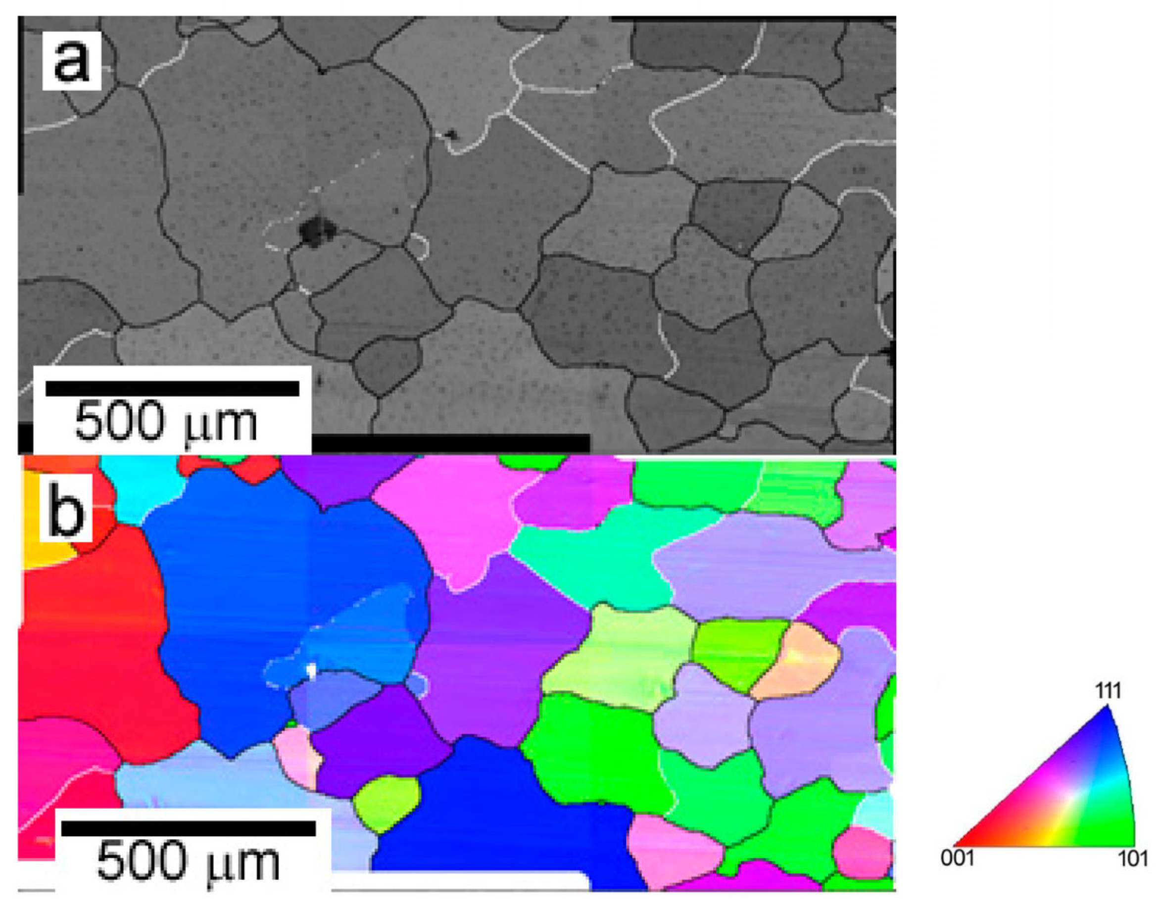
3.1. As-Cast Material

The microstructure of the alloy in the as-cast condition is shown in Figure 1. A single-phase structure consisting of coarse inhomogeneous equiaxed grains, whose size ranges from 150 to 550 μm, is observed. Most of the grain boundaries are high-angle, but also certain grains separated by low-angle boundaries are also present. Misorientation within the grains is practically absent, so it can be considered that the microstructure is free of deformation.

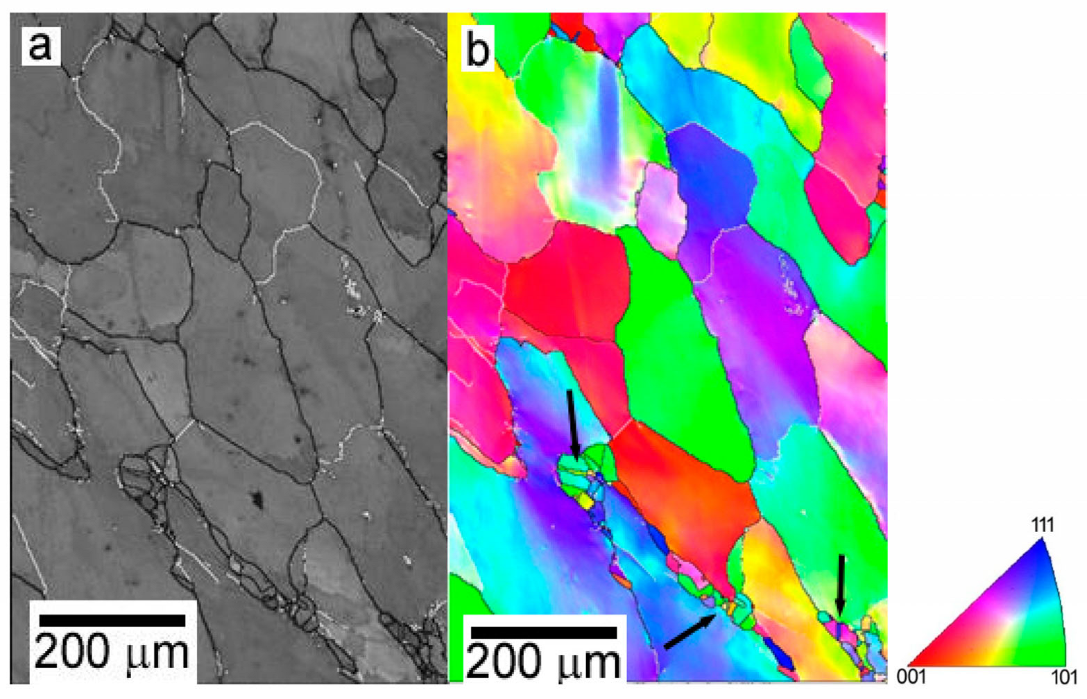
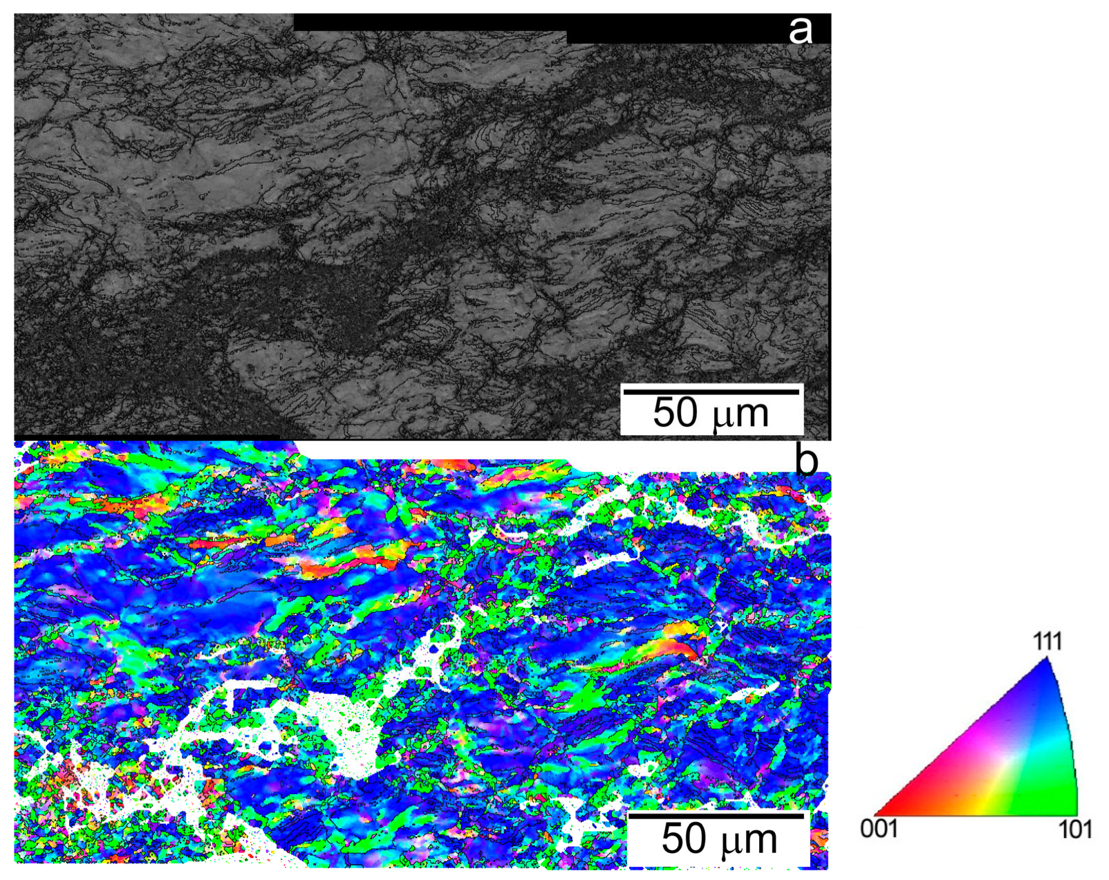
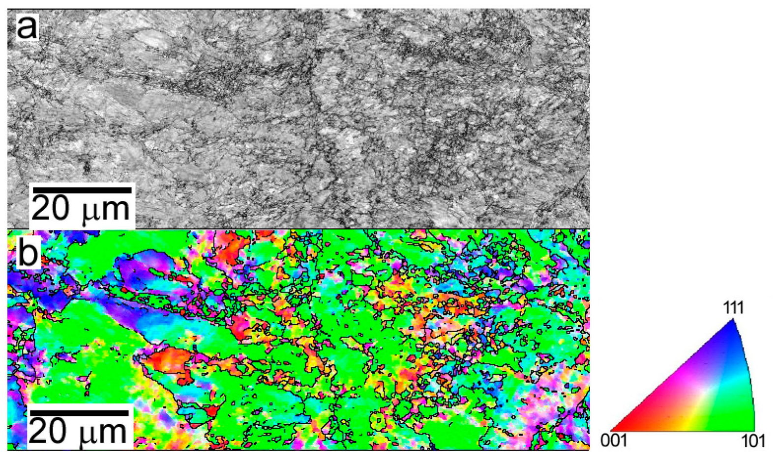
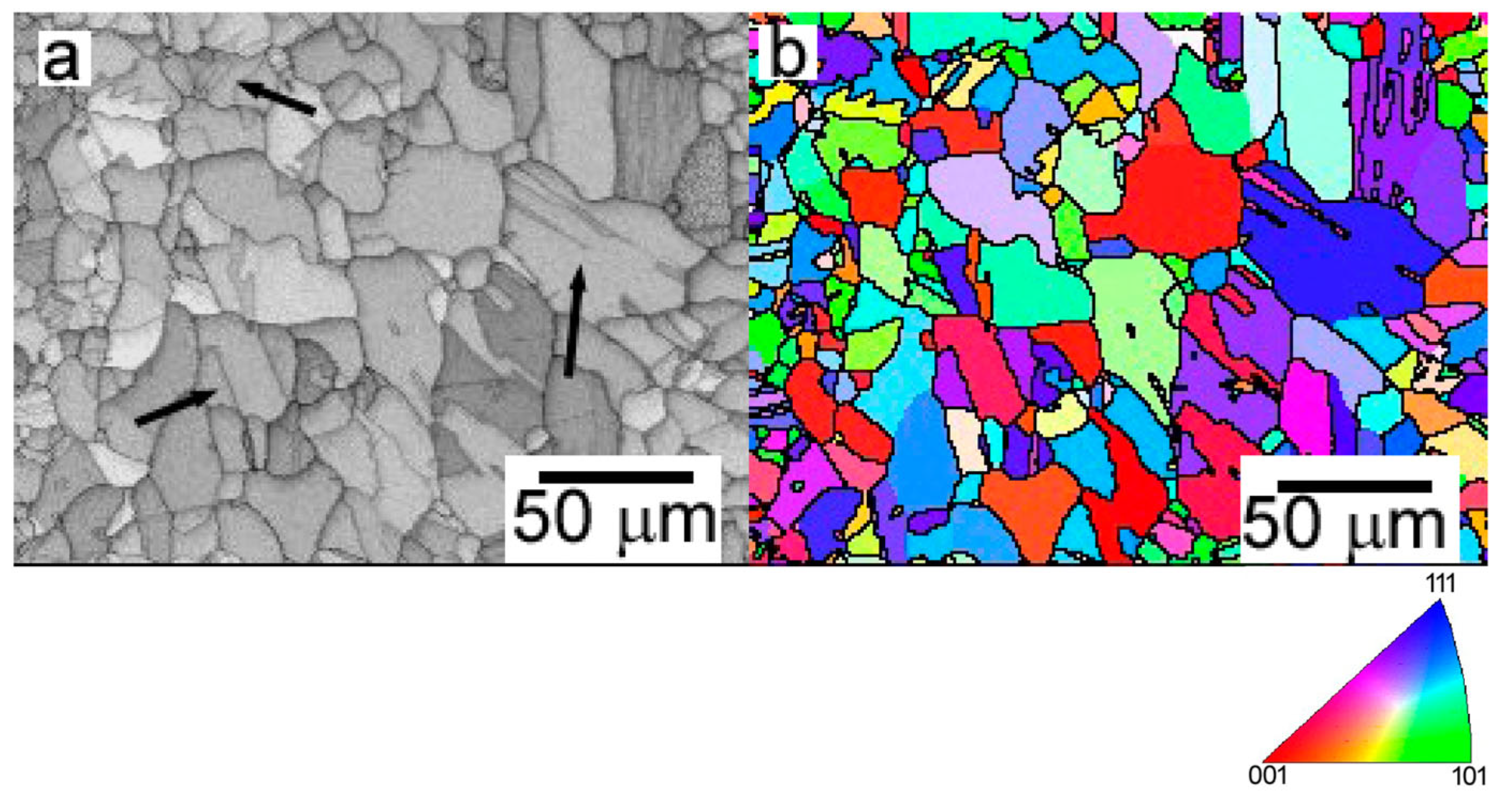
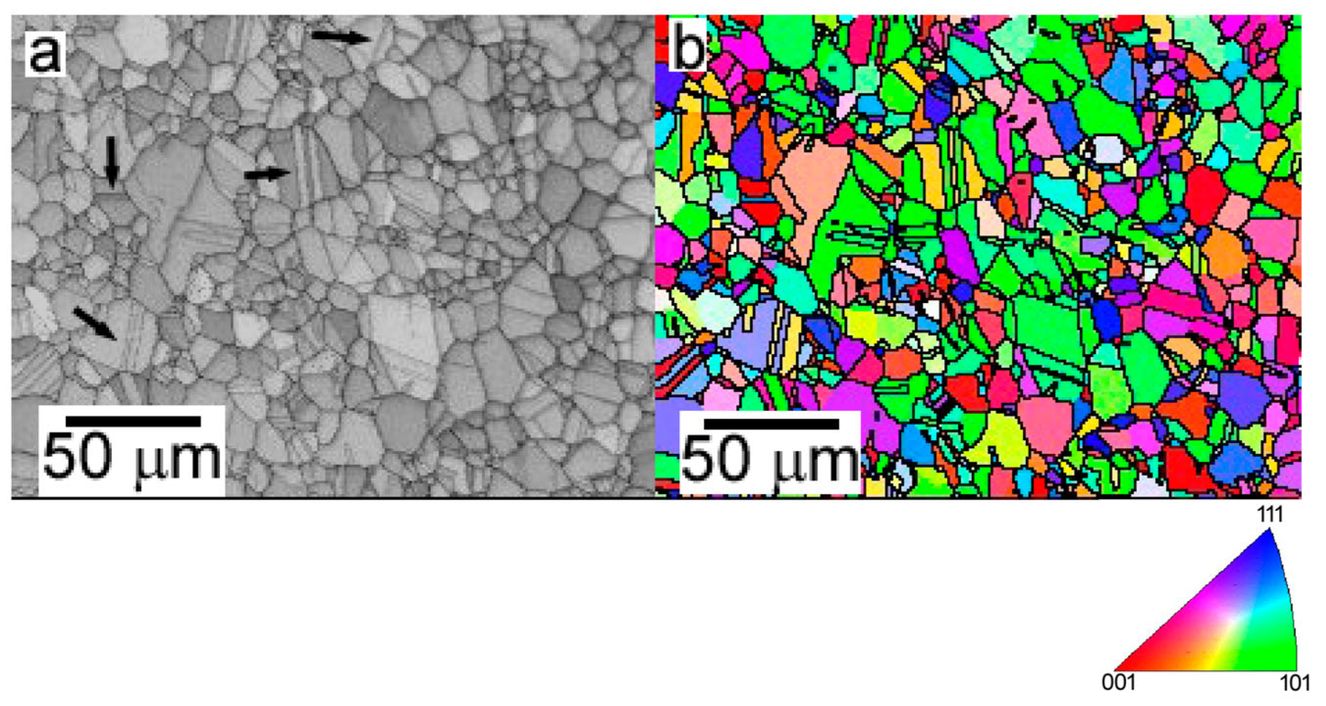
3.2. Thermomechanical Processing

The microstructure of the as-cast alloy evolves during forging at 1200 °C, as shown in Figure 2. During forging, the piece flows perpendicularly to the applied load. As result, the grains are no longer equiaxed, but elongated. The grains are up to 650 μm long and about 150–175 μm wide. The deformation introduced during the forging promotes the occurrence of dynamic recrystallization (DRX) at certain grain boundaries/triple points of the original parent grains. Although the size of DRXed grains is much smaller than that of the original grains, the high temperature of the forging process which can even extend during the earliest stages of the cooling down results in a considerable grain growth in such a way that most of the DRXed grains ranges between 40 and 50 μm. Many of these new recrystallized grains contain also recrystallization twins (examples of them are marked by black arrows in Figure 2b). Compared to the as-cast microstructure, it is interesting to note the increase in misorientation within non-recrystallized grains, although large differences can be found depending on the orientation of the grains.
The as-cast ingot could be cold-rolled at room temperature with a reduction of 83% without any cracking. The initial grains are highly elongated along the rolling direction. IQ and IPF + IQ images reveal large distortions induced during the rolling process over the entire grain, which are significantly magnified within the bands distributed throughout the grain (Figure 3). It can be checked the existence of many regions in which the orientation is slightly deviated from that of the (111) plane of the parent grain. The numerous high-angle grain boundaries (HAGBs) within the parent grains usually define elongated regions with similar orientations which could be ascribed to deformation twins, as those reported during cold-rolling of numerous single phase fcc-HEAs [20,21,22]. On the other hand, an abrupt change in the orientation of the parent grain is found within the bands, exhibiting normally these regions a (101) orientation. Moreover, there is a fine dispersion of small domains exhibiting different orientations embedded in the bands, which could be considered as recrystallized grains. This means that inside the bands the strain becomes concentrated enough to induce huge local changes in orientation within the parent grains (see Figure 3).
The microstructure of the sheet rolled at 450 °C resembles, in some way, that observed in the CR alloy. Thus, the parent grains remain highly elongated along the rolling direction although the dislocation density inside them seems to be lower than that found in the CR alloy (see Figure 4). Probably, re-heating during intermediate rolling steps, for assuring the 450 °C temperature through the overall rolling process, assists certain dislocation annihilation through recovery processes. Anyway, also, drastic changes in orientation are found within the parent grains, as found in the CR alloy. Unlike the CR material, elongation of coarse grains along the rolling direction is not well defined because the microstructure of the alloy consists of a combination of fine-grained regions embedded in coarse-grained regions which maintain the orientation of the parent grains. Moreover, a wide range of sizes can be distinguished within the fine-grained regions: (1) Recrystallized grains with an average grain size of about 1 μm, resulting from the high strain stored in local regions of the alloy as those existing in the CR material and (2) larger grains up to 10–15 μm in size, outlined by high-angle grain boundaries. In both cases, their orientations are far from that of the parent grain. This suggests that the strain in these regions is not enough for inducing the nucleation of new grains but it is enough for causing large local changes in orientation which leads to the formation of new grains through bulging and subdivision processes within the parent grains.
Figure 5 shows the microstructure of the alloy warm rolled at 850 °C with a total reduction of 50%. A bimodal microstructure can be clearly observed; coarse elongated and fine equiaxed grains. During initial stages of rolling, coarse equiaxed grains existing in the as-cast ingot deform along the rolling direction. Nevertheless, the deformation becomes inhomogeneous as the rolling proceeds, which depends on the initial orientation of the equiaxed grains existing in the as-cast ingots. Such microstructural evolution arises from the occurrence or not of DRX. If the strain accumulated within the coarse elongated grains does not exceed a critical value, no DRX takes place. Deformation introduced during rolling just causes slight changes in orientation inside the grain, usually not larger than 3–4° among neighbor points, which affect the overall grain and lead to the development of large subgrains (see Figure 5). When the strain accumulated within the elongated grains exceeds a critical value, DRX takes place, leading to an equiaxed fine-grained structure. Moreover, the uneven distribution of stresses between adjacent grains also influences the local strain distribution within the coarse-non-DRXed grains. Thus, misorientation between opposite grain boundaries of coarse elongated grains becomes up to 15–17°, which changes gradually from one border to the other. Figure 6 presents a detail of the DRXed grains’ regions. The grain sizes range from 5 to 25 μm, and recrystallization twins are often found, although not exclusively, within the coarsest grains. It is interesting to note the misorientation zones inside the DRXed grains. This indicates that DRXed grains undergo additional deformation during subsequent rolling steps.
The microstructure of the rolled sheet changes drastically if rolling continues until completing a total reduction of 83%. In this case, the entire microstructure corresponds to DRXed grains, although the grain size is rather heterogeneous because of the coexistence of coarse and fine grains (see Figure 7). Thus, the grain size oscillates between 5 and 40 μm and as a general rule is finer than that of DRXed grains in the HR850-6 material. Numerous recrystallization twins are found disregarding the size of DRXed grains. The low resolution of the grains in the IQ image indicates that the microstructure is highly deformed, more than the DRXed grains in the HR850-6 material. This assumption is corroborated in the IPF + IQ map, where clear orientation changes are noticed inside the DRXed grains. In addition, a low fraction of very small grains of about 1–2 μm appears at grain boundaries of DRXed grains (see encircled areas in Figure 7b). This suggests that deformation introduced in some DRXed grains during successive rolling is enough to promote the nucleation of new secondary DRXed grains, mainly at grain boundaries of the primary DRXed grains.

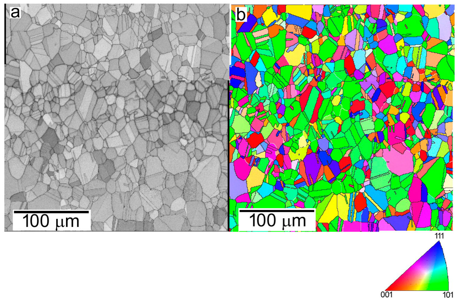
3.3. Annealing of CR Sheets

Figure 8 presents the microstructure of the CR alloy after annealing for 1 h at 500 °C. The coarse-grained structure of the CR alloy is kept, but the IQ image reveals the absence of the large bands where the deformation was markedly concentrated, although there are still highly deformed regions whose orientations are far from that of the parent grain. In these regions, even, some small grains are recognized, which probably could correspond with the smallest grains existing in the CR alloy as a result of bulging and subdivision processes. A major part of the parent grain consists of a substructure constituted by almost parallel narrow bands which are instead subdivided into more or less equiaxed subgrains. This suggests that both annihilation of dislocations and accumulation of dislocations to develop low angle boundaries (LAB) account for the observed microstructure.
The microstructure of the CR sheet evolves significantly when the temperature of annealing is increased to 600 °C. After 1 h of annealing, the volume fraction of regions maintaining the orientation of the parent grain decreased drastically while the fraction of regions with different orientations increased considerably with respect to that observed during the annealing at 500 °C (see Figure 9). Most of these misoriented regions appear as long grains with serrated HAGBs within the parent grains. The irregular morphology of these new grains suggests that the continuous accumulation of dislocations at certain subgrain boundaries increased the misorientation with respect to their corresponding parent grains, leading to the formation of new grains [23]. However, some misorientation is still noticed within these recrystallized grains, which is an indication that not all the dislocations were absorbed in the low-angle grain boundaries (LAGBs) to transform into HAGBs. In addition, very few fine equiaxed grains can be sparsely distributed through the entire parent grain. Probably, these small grains arise from the nucleation of new grains in highly deformed regions preexisting in the CR alloy, which hardly grow at this low temperature.
The microstructure of the alloy after annealing at 700 °C is presented in Figure 10. The strongly deformed structure of the CR material statically recrystallized as equiaxed grains, not retaining any vestige of the coarse elongated parent grains. Therefore, 700 °C can be considered as the minimum temperature at which an equiaxed fine-grained microstructure can be readily developed after short annealing times. However, there is a large dispersion in grain sizes. Coarse- and fine-grained regions can be distinguished. In the first ones, the grain size ranges between 6 and 25 μm while the grain size varies between 1 and 3 μm in the second ones. Fine-grained regions are usually located as long strips separating the different coarse-grained regions. Recrystallization twins are observed profusely at both grain size distributions. The bimodal distribution can be correlated with the inhomogeneous distribution of the deformation inside the parent grains of the CR alloy. Thus, nucleation of new grains will start in those regions where deformation is accumulated while in other regions the beginning of recrystallization will be delayed. Consequently, further grain growth will proceed firstly where the new grains are nucleated, leading to coarse-grained areas, whereas nucleation of new statically recrystallized grains will render the fine-grained areas simultaneously. Annealing twins are usually considered to be caused by a stacking error when a grain boundary is migrating [24], although other theories propose that they are generated when the grain boundary hardly advances in the deformed region because of its low dislocation density and/or low misorientation angle. In any case, stagnant grains cannot continue to grow because the driving force was insufficient for boundary migration. At this point, twin formation alters the misorientation angle in such a way that grain growth can resume [25]. The density of twins is larger in fine-grained regions, frequently dividing completely the recrystallized grain in two halves. In coarse-grained regions, however, the size of the twins is smaller compared to the grains in which they are contained. This indicates that coarse grains can grow rapidly due to the high dislocation density in their surroundings, so no twin formation is required until their growth overlaps with the growth of other grains. Otherwise, the grain growth is rapidly arrested in fine-grained regions because all nuclei are formed almost simultaneously. Since the dislocation density decreases sharply, the growth of these new recrystallized grains would slow down. At this point, twin formation provides the boundary energy for further growth at those positions where the driving force for grain boundary migration is low [25].
The microstructures of the alloys annealed at 800, 850, 900 and 950 °C for 1 h are presented from Figure 11, Figure 12, Figure 13, Figure 14 and Figure 15. The microstructure is similar at all temperatures, although the higher the temperature is the coarser the grain size is. As found after annealing at 700 °C, the microstructure is always bimodal, combining coarse- and fine-grained areas. This suggests an identical mechanism for developing this bimodal recrystallized microstructure. The grain size of coarse-grained areas ranges between 10 and 25 μm at 800 °C, 20 and 60 μm at 850 °C, 25 and 60 at 900 °C and 50–60 μm at 950 °C. On the other hand, the grain size of fine-grained regions shifts between 2 and 7 μm at 800 °C, 3 and 10 μm at 850 °C, 15 and 30 μm at 900 °C and 20 and 40 μm at 950 °C. The evolution of the grain size with the annealing temperature evidences that grain growth is rapidly saturated in coarse-grained regions. The maximum grain size of statically recrystallized grains hardly increases beyond 850 °C, with a maximum value of about 60 μm. This means that grain growth above 850 °C is mainly restricted to fine-grained regions. This indicates a lower driving force for grain growth in these regions because of the low dislocation density and the reduction in grain boundary energy related to the progressive decrease in the total grain boundary area. Oppositely, grain growth is favored in fine-grained regions because the large grain boundary area provides the driving force necessary for decreasing the surface energy in these regions. Thus, the grain size of fine-grained regions tends to approach the grain size of coarse-grained regions with the increasing annealing temperature.

3.4. Microhardness

The Vickers microhardness values for all the studied materials are shown in Table 4. It can be checked that the hardness of the thermo-mechanically processed alloys increases with decreasing the temperature of processing, attaining a maximum of 363 HV for the WR450-2 alloy. In the case of the annealed alloys, the microhardness increases, compared with the CR alloy, as the annealing temperature increases, with a maximum value at 500 °C. Only at temperatures above 600 °C, the microhardness drops to very small values. A similar behavior has been reported for other HEAs [21,26]. Therefore, recrystallization and subsequent grain growth of the CR material induce considerable softening, which becomes higher as the grain size of the alloy increases. If a given temperature is considered, the microhardness of the material thermo-mechanically treated is higher than that of the annealed material. Thus, hardness of the HR850-6 alloy is almost two times that of the CR + TT850 alloy. Moreover, an increase in rolling reduction at 850 °C also causes an increase of about 40 HV for the HR850-2 alloy compared to HR850-6 alloy. Consequently, the differences in hardness have to be correlated with changes in the dislocation density existing in the materials, which is very high in the case of thermo-mechanically processed alloys while statically recrystallized alloys resulting from annealing treatments are almost totally free of dislocations. It is interesting to note that microhardness of the WR450-2 is higher than that of the CR alloy. This behavior could be also connected with the anomalous increase in microhardness measured in the alloy annealed from 400 to 600 °C with respect to the CR alloy. It was proposed that such an increase is associated with solute segregation to stacking faults and short-range ordering [26]. To check this point, differential scanning calorimetry (DSC) tests in the CR material were carried out at heating rates from 40 to 70 °C/min. Three peaks can be clearly observed in the DSC curve, as shown in Figure 16. The first one can be identified between 225 and 300 °C. The nature of microstructural changes associated with this first peak is not clear, but it could be associated with recovery processes occurring in the crystalline lattice through the elimination or rearrangement of defects such as vacancies or dislocations generated during cold rolling as a way for reducing the stored energy in the CR microstructure. The second one between 350 and 450 °C agrees rather well with the increase in hardness measured in the CR alloy annealed at 400 and 500 °C and the WR450-2 alloy. This interval of temperatures coincides also with that reported for the occurrence of the dynamic strain-ageing phenomenon in other HEAs [27,28]. Therefore, it is reasonable to assume that during thermo-mechanical processing and/or annealing within this range of temperatures, solute atoms can diffuse to the core of dislocations, pinning their movement, which results in an increase in hardness. It is evident that the third peak between 550 and 650 °C corresponds to recrystallization.

4. Conclusions

From the present study, the following conclusions can be drawn:
(1)
The microstructure of the single-phase fcc-based Al5Co15Cr30Fe25Ni25 HEA can be tuned through the proper choice of the thermo-mechanical processing and thermal treatments in such a way that hardness can be increased up to three times that of the as-cast alloy.
(2)
The occurrence or not of recrystallization during thermo-mechanical and annealing treatments determines the mechanical strength of the HEA. Complete recrystallization of annealed samples is attained after 1 h of exposure at 700 °C, inducing considerable softening.
(3)
The degree of recrystallization during thermo-mechanical processing of Al5Co15Cr30Fe25Ni25 HEA depends on the reduction applied to the material and the orientation of parent grains in the as-cast alloy.
(4)
Maximum hardening is found for the alloy warm rolled at 450 °C and the cold-rolled alloy annealed at 500 °C for 1 h. This indicates that thermo-mechanical processing or annealing treatments below 600 °C induce an additional hardening associated with the pinning effect of solute atoms located at the core of dislocations.

Author Contributions

Conceptualization, P.P.; methodology, P.P. and P.A.; validation, J.M. and M.F.V.; formal analysis, J.M., P.A. and P.P.; investigation, G.G., J.M., M.F.V., P.A. and P.P.; writing—original draft preparation, P.P.; writing—review and editing, G.G., J.M., M.F.V., P.A. and P.P.; supervision, P.P.; funding acquisition, P.P. All authors have read and agreed to the published version of the manuscript.

Funding

This research was funded by the Spanish Ministry of Science and Innovation under project PID2019-104382RBI00.

Data Availability Statement

The raw/processed data required to reproduce these findings cannot be shared at this time as the data also form part of an ongoing study.

Acknowledgments

The authors acknowledge the technical assistance of A. Tomas during EBSD measurements at the Microscopy Laboratory of CENIM as well as the assistance of C. Peña and M.A. Acedo for forging and rolling tasks.

Conflicts of Interest

The authors declare no conflict of interest.

References

  1. Zhang, Y.; Yang, X.; Liaw, P.K. Alloy design and properties optimization of high-entropy alloys. JOM 2012, 64, 830–838. [Google Scholar] [CrossRef]
  2. Zhang, Y.; Zuo, T.; Tang, Z.; Gao, M.C.; Dahmen, K.A.; Liaw, P.K.; Lu, Z.P. Microstructures and properties of high-entropy alloys. Prog. Mater. Sci. 2014, 61, 1–93. [Google Scholar] [CrossRef]
  3. Pickering, E.J.; Jones, N.G. High-entropy alloys: A critical assessment of their founding principles and future prospects. Int. Mater. Rev. 2016, 61, 183–202. [Google Scholar] [CrossRef] [Green Version]
  4. Miracle, D.B.; Senkov, O.N. A critical review of high entropy alloys and related concepts. Acta Mater. 2017, 122, 448–511. [Google Scholar] [CrossRef] [Green Version]
  5. Gorsse, S.; Nguyen, M.H.; Senkov, O.N.; Miracle, D.B. Database on the mechanical properties of high entropy alloys and complex concentrated alloys. Data Br. 2018, 21, 2664–2678. [Google Scholar] [CrossRef]
  6. Munitz, A.; Salhov, S.; Hayun, S.; Frage, N. Heat treatment impacts the micro-structure and mechanical properties of AlCoCrFeNi high entropy alloy. J. Alloy Compd. 2016, 683, 221–230. [Google Scholar] [CrossRef]
  7. Hachet, D.; Gorsse, S.; Godet, S. Microstructure study of cold rolled Al0.32CoCrFeMnNi high-entropy alloy: Interactions between recrystallization and precipitation. Mater. Sci. Eng. A 2021, 802, 140452. [Google Scholar] [CrossRef]
  8. Wu, Y.; Jin, X.; Zhang, M.; Yang, H.; Qiao, J.; Wu, Y. Yield strength-ductility trade-off breakthrough in Co-free Fe40Mn10Cr25Ni25 high-entropy alloys with partial recrystallization. Mater. Today Commun. 2021, 28, 102718. [Google Scholar] [CrossRef]
  9. Sabban, R.; Dash, K.; Suwas, S.; Murty, B.S. Strength–Ductility synergy in high entropy alloys by tuning the thermo-mechanical process parameters: A comprehensive review. J. Indian Inst. Sci. 2022, 102, 91–116. [Google Scholar] [CrossRef]
  10. Mahmoud, E.R.I.; Shaharoun, A.; Gepreel, M.A.; Ebied, S. Studying the effect of cold rolling and heat treatment on the microstructure and mechanical properties of the Fe36Mn20Ni20Cr16Al5Si3 High Entropy Alloy. Entropy 2022, 24, 1040. [Google Scholar] [CrossRef]
  11. Jia, Z.Y.; Zhang, S.Z.; Huo, J.T.; Zhang, C.J.; Zheng, L.W.; Kong, F.T.; Li, H. Heterogeneous precipitation strengthened non-equiatomic NiCoFeAlTi medium entropy alloy with excellent mechanical properties. Mater. Sci. Eng. A 2022, 834, 142617. [Google Scholar] [CrossRef]
  12. Liu, Z.; Xiong, Z.; Chen, K.; Cheng, X. Large-size high-strength and high-ductility AlCoCrFeNi2.1 eutectic high-entropy alloy produced by hot-rolling and subsequent aging. Mater. Lett. 2022, 315, 131933. [Google Scholar] [CrossRef]
  13. Huang, X.; Miao, J.; Li, S.; Taylor, C.D.; Luo, A.A. Co-free CuFeMnNi high-entropy alloy with tunable tensile properties by thermomechanical processing. J. Mater. Sci. 2021, 56, 7670–7680. [Google Scholar] [CrossRef]
  14. Yi, H.; Xie, R.; Zhang, Y.; Wang, L.; Tan, M.; Li, T.; Wei, D. Tuning Microstructure and Mechanical Performance of a Co-Rich Transformation-Induced Plasticity High Entropy Alloy. Materials 2022, 15, 4611. [Google Scholar] [CrossRef]
  15. Yang, Z.; Yan, D.; Lu, W.; Li, Z. A TWIP-TRIP quinary high-entropy alloy: Tuning phase stability and microstructure for enhanced mechanical properties. Mater. Sci. Eng. A 2021, 801, 140441. [Google Scholar] [CrossRef]
  16. Li, X.; Li, Z.; Wu, Z.; Zhao, S.; Zhang, W.; Bei, H.; Gao, Y. Strengthening in Al-, Mo- or Ti-doped CoCrFeNi high entropy alloys: A parallel comparison. J. Mater. Sci. Tech. 2021, 94, 264–274. [Google Scholar] [CrossRef]
  17. Mohammad-Ebrahimi, M.H.; Zarei-Hanzaki, A.; Abedi, H.R.; Vakili, S.M.; Soundararajan, C.K. Decelerated grain growth kinetic and effectiveness of Hall-Petch relationship in a cold-rolled non-equiatomic high entropy alloy. J. Alloy Compd. 2021, 874, 159849. [Google Scholar] [CrossRef]
  18. Rajendrachari, S. An Overview of high-entropy alloys prepared by mechanical alloying followed by the characterization of their microstructure and various properties. Alloys 2022, 1, 116–132. [Google Scholar] [CrossRef]
  19. Rajendrachari, S.; Adimule, V.; Gulen, M.; Khosravi, F.; Somashekharappa, K.K. Synthesis and Characterization of High Entropy Alloy 23Fe-21Cr-18Ni20Ti-18Mn for Electrochemical Sensor Applications. Materials 2022, 15, 7591. [Google Scholar] [CrossRef]
  20. Gangireddy, S.; Whitaker, D.; Mishra, R.S. Significant contribution to strength enhancement from deformation twins in thermomechanically processed Al0.1CoCrFeNi microstructures. J. Mater. Eng. Perf. 2019, 28, 1661–1667. [Google Scholar] [CrossRef]
  21. Haase, C.; Barrales-Mora, L.A. Influence of deformation and annealing twinning on the microstructure and texture evolution of face-centered cubic high entropy alloys. Acta Mater. 2018, 150, 88–103. [Google Scholar] [CrossRef] [Green Version]
  22. Santos, L.A.; Singh, S.; Rollett, A.D. Microstructure and texture evolution during thermomechanical processing of Al0.25CoCrFeNi high-entropy alloy. Met. Mater. Trans. A 2019, 50, 5433–5444. [Google Scholar] [CrossRef]
  23. Gourdet, S.; Montheillet, F. A model of continuous dynamic recrystallization. Acta Mater. 2003, 51, 2685–2699. [Google Scholar] [CrossRef]
  24. Jin, Y.; Lin, B.; Bernacki, M.; Rohrer, G.S.; Rollet, A.D.; Bozzolo, N. Annealing twin development during recrystallization and grain growth in pure nickel. Mater. Sci. Eng. A 2014, 597, 295–303. [Google Scholar] [CrossRef] [Green Version]
  25. Field, D.P.; Bradford, L.T.; Nowell, M.M.; Lillo, T.M. The role of annealing twins during recrystallization of Cu. Acta Mater. 2007, 55, 4233–4241. [Google Scholar] [CrossRef]
  26. Otto, F.; Hanold, N.L.; George, E.P. Microstructural evolution after thermomechanical processing in an equiatomic, single-phase CoCrFeMnNi high-entropy alloy with special focus on twin boundaries. Intermetallics 2014, 54, 39–48. [Google Scholar] [CrossRef]
  27. Tsai, C.W.; Lee, C.; Lin, P.T.; Xie, X.; Chen, S.; Carroll, R.; LeBlanc, M.; Brinkman, B.A.W.; Liaw, P.K.; Dahmen, K.A.; et al. Portevin-Le Chatelier mechanism in face-centered-cubic metallic alloys from low to high entropy. Int. J. Plast. 2019, 122, 212–224. [Google Scholar] [CrossRef]
  28. Chen, S.Y.; Wang, L.; Li, W.D.; Tong, Y.; Tseng, K.K.; Tsai, C.W.; Yeh, J.W.; Ren, Y.; Guo, W.; Poplawsky, J.D.; et al. Peierls barrier characteristic and anomalous strain hardening provoked by dynamic-strain-aging strengthening in a body-centered-cubic high-entropy alloy. Mater. Res. Lett. 2019, 7, 475–481. [Google Scholar] [CrossRef]
Figure 1. Microstructure of the Al5Co15Cr30Fe25Ni25 HEA in the as-cast condition obtained from EBSD measurements. (a) IQ, (b) IPF + IQ map. The scanned area is 1730 × 860 μm2, and the step size is 2.5 μm. White lines represent low-angle boundaries (<4°).
Metals 13 00180 g001
Figure 2. Microstructure of FG1200 HEA. The map was taken in a section perpendicular to the forging direction. (a) IQ and (b) IPF+IQ map. The scanned area is 600 × 872 μm2; the step size is 2 μm. The black arrows mark twins within the recrystallized grains.
Metals 13 00180 g002
Figure 3. Detail of the microstructure inside an individual grain of the CR HEA, (a) IQ, (b) IPF + IQ map. The scanned area is 233 × 122 μm2, and the step size is 0.3 μm.
Metals 13 00180 g003
Figure 4. Detail of the microstructure inside a single grain of the WR450-2 HEA. (a) IQ, (b) IPF + IQ map. The scanned area is 118 × 45 mm2, and the step size is 0.2 μm.
Metals 13 00180 g004
Figure 5. General view of the microstructure corresponding to the HR850-6 HEA. (a) IQ, (b) IPF + IQ map. The scanned area is 1196 × 890 μm2, and the step size is 4 μm.
Metals 13 00180 g005
Figure 6. Detail of the equiaxed fine-grained region of the HR850-6 HEA. (a) IQ, (b) IPF + IQ map. The scanned area is 120 × 89 μm2, and the step size is 0.4 μm. The black arrows indicate some examples of recrystallization twins.
Metals 13 00180 g006
Figure 7. Detail of the microstructure of the HR850-2 HEA. (a) IQ, (b) IPF + IQ map. The scanned area is 120 × 89 μm2, and the step size is 0.4 μm. The black arrows indicate some examples of recrystallization twins. Encircled areas indicate new grains formed at grain boundaries of certain DRXed grains.
Metals 13 00180 g007
Figure 8. Detail of the microstructure of the CR + TT500 HEA. (a) IQ, (b) IPF + IQ map. The scanned area is 243 × 330 μm2, and the step size is 0.7 μm. Green color depicts the orientation of the parent grain.
Metals 13 00180 g008
Figure 9. Detail of the microstructure of the CR + TT600 HEA. (a) IQ, (b) IPF + IQ map. The scanned area is 48 × 72 μm2, and the step size is 0.15 μm. Green color depicts the orientation of the parent grain.
Metals 13 00180 g009
Figure 10. Microstructure of the CR + TT700 HEA. (a) IQ, (b) IPF + IQ map. The scanned area is 316 × 241 μm2, and the step size is 0.5 μm.
Metals 13 00180 g010
Figure 11. Microstructure of the CR + TT800 HEA. (a) IQ, (b) IPF + IQ map. The scanned area is 236 × 179 μm2, and the step size is 0.4 μm.
Metals 13 00180 g011
Figure 12. Microstructure representative of fine-grained regions of CR + TT850 HEA. (a) IQ, (b) IPF + IQ map. The scanned area is 80 × 60 μm2, and the step size is 0.3 μm. The black arrows indicate examples of recrystallization twins.
Metals 13 00180 g012
Figure 13. Microstructure representative of coarse-grained regions of the CR + TT850 HEA. (a) IQ, (b) IPF + IQ map. The scanned area is 239 × 180 μm2, and the step size is 1 μm. The black arrows indicate examples of recrystallization twins.
Metals 13 00180 g013
Figure 14. Microstructure representative of the CR + TT900. (a) IQ, (b) IPF + IQ map. The scanned area is 239 × 180 μm2, and the step size is 1 μm. The black arrows indicate examples of recrystallization twins.
Metals 13 00180 g014
Figure 15. Microstructure representative of the CR + TT950. (a) IQ, (b) IPF + IQ map. The scanned area is 302 × 316 μm2, and the step size is 0.8 μm.
Metals 13 00180 g015
Figure 16. DSC curves of the CR alloy at heating rates of 40, 50, 60 and 70 °C/min.
Metals 13 00180 g016
Table 1. Real composition, given in atomic percentage, of the HEA ingot in the as-cast condition determined from at least five EDS measurements.
CompositionAlCoCrCoNi
Nominal515302525
Real4.6 ± 0.115.9 ± 0.331.1 ± 0.324.1 ± 0.124.3 ± 0.2
Table 2. List of thermo-mechanical treatments performed over the as-cast ingots.
ConditionTemperature
(°C)
DesignationReduction
(%)
Final Thickness (mm)
Forging1200FG120050 (1 step)30
Cold rolling25CR86 (0.5 mm per pass)1
Warm rolling450WR450-283 (1 mm per pass)2
Hot rolling850HR850-650 (1.5 mm per pass)6
Hot rolling850HR850-283 (1.5 mm per pass)2
Table 3. Temperatures applied during annealing for 1 h of cold rolled sheets.
Temperature (°C)Designation
400CR + TT400
500CR + TT500
600CR + TT600
700CR + TT700
800CR + TT800
850CR + TT850
900CR + TT900
950CR + TT950
Table 4. Influence of thermomechanical processing and annealing temperature on the Vickers microhardness of thermo-mechanically and thermally treated Al5Co15Cr30Fe25Ni25 HEA.
MaterialMicrohardness Vickers (kg/mm2)
As cast121 ± 5
FG1200157 ± 6
HR850-6267 ± 2
HR850-2309 ± 5
WR450-2363 ± 5
CR318 ± 9
CR + TT400342 ± 9
CR + TT500380 ± 6
CR + TT600 339 ± 12
CR + TT700203 ± 6
CR + TT800190 ± 8
CR + TT850165 ± 4
CR + TT900144 ± 2
CR +TT950127 ± 3
Disclaimer/Publisher’s Note: The statements, opinions and data contained in all publications are solely those of the individual author(s) and contributor(s) and not of MDPI and/or the editor(s). MDPI and/or the editor(s) disclaim responsibility for any injury to people or property resulting from any ideas, methods, instructions or products referred to in the content.

