Article

Mechanism of Layer Formation during Gas Nitriding of Remelted Ledeburitic Surface Layers on Unalloyed Cast Irons

1
Institute of Materials Engineering, Technische Universität Bergakademie Freiberg, 09599 Freiberg, Germany
2
Institute of Materials Science, Technische Universität Bergakademie Freiberg, 09599 Freiberg, Germany
*
Author to whom correspondence should be addressed.
Metals 2023, 13(1), 156; https://doi.org/10.3390/met13010156
Submission received: 25 November 2022 / Revised: 6 January 2023 / Accepted: 7 January 2023 / Published: 12 January 2023
(This article belongs to the Special Issue Advances in Metallic Heat Treatment and Surface Engineering)

Abstract

:
Unalloyed cast iron materials exhibit low tribological and corrosive resistance. In this respect, nitriding has a wide range of applications for steels. In the case of cast iron, the advantageous properties of nitrided layers are impaired by the presence of graphite. Electron beam remelting of cast iron surfaces prior to nitriding removes graphite. The homogeneous ledeburitic microstructure within the approx. 1 mm-thick remelted layer enables the formation of a dense compound layer during subsequent nitriding. The main objective of this study is to investigate the nitriding mechanism of unalloyed ledeburitic microstructures. Due to the complex relationships, investigations were carried out on both conventional ferritic and pearlitic cast irons and Fe-based model alloys containing one to four additional alloying elements, i.e., C, Si, Mn and Cu. The iron (carbo-)nitride composition (γ’, ε) of this compound layer depends on the gas nitriding conditions, the chemical composition of the substrates and the microstructural constituents. As a result, a schematic model of the nitriding mechanism is developed that includes the effects of the nitriding parameters and alloy composition on the phase composition of the nitriding layer. These findings enable targeted parameter selection and a further optimization of both the process and the properties.

1. Introduction

Similar to steels, unalloyed cast irons can be strengthened and/or their corrosion resistance can be improved using thermal or thermochemical surface treatments, such as surface hardening, nitriding and boriding, among others [1,2,3]. In the aforementioned solid-phase processes, it is common that only the ferritic or pearlitic matrix of the cast irons is hardened while the soft graphite contained in the cast irons is retained, which severely impairs any improvement in the desired surface properties. By using a liquid-phase process, such as electron beam remelting (EBR), near-surface graphite can be dissolved and a hard ledeburitic microstructure can be produced as a result of the process-inherent (rapid) self-quenching. For improving both the tribological and corrosion behavior, nitriding can be employed after the electron beam remelting process [3,4]. This duplex treatment enables the formation of a thin, dense, defect-and graphite-free nitride layer (compound layer) on a thicker, harder support layer. The high hardness of the support layer results from the precipitation of alloying element nitrides in the diffusion layer (nitriding) as well as from the large volume fraction of eutectic cementite in the white-solidified surface layer (EBR). Previous studies on the thermal stability of white-solidified cast iron surfaces indicated that nitriding must be performed at temperatures <600 °C to avoid a decrease in hardness that results from cementite coarsening and/or graphitization [5].
For a reproducible and targeted design of the compound and diffusion layers, an in-depth understanding of the nitriding mechanism as well as the associated process- and alloy-related factors are necessary. Previous nitriding experiments showed that the high silicon content (2–3 wt%) of cast irons and its distribution after remelting had a decisive influence on the local phase composition of the nitride layers formed as a function of the nitriding conditions [6,7,8]. Si and further alloying elements, such as Mn and Cu contained in both cast iron and steel were shown to characteristically affect phase formation and selection during the compound layer growth [9,10,11].
In order to systematically study the effects of the alloying elements observed on remelted commercially available cast-iron alloys with different matrix microstructures (ferrite, pearlite) and/or graphite morphologies, Fe-based model alloys containing one to four additional alloying elements (C, Si, Mn, Cu) were investigated. The knowledge gained resulted in a comprehensive nitriding mechanism model presented below, which illustrates the complex interrelation of the microstructure and the effects of the alloying elements involved in nitriding remelted white-solidified cast iron. This paper compares the results obtained from the investigation of the nitrided model alloys and commercially available cast iron alloys. In doing so, both new and previously published results are discussed.

2. Materials and Methods

2.1. Materials and Parameters of the Surface Treatments

This investigation involved the use of commercially available pearlitic and ferritic cast iron materials with lamellar (GJL), spheroidal (GJS) and vermicular graphite (GJV), which were provided in the form of flat specimens (100 × 60 × 20 mm3) by the foundry Kessler & Co., Leipzig, Germany (Table 1). Electron beam remelting (EBR) was carried out in a K26-80/15 universal electron beam facility (chamber volume 2.6 m3, maximum acceleration voltage 80 kV, maximum beam power 15 kW). To avoid cracking upon solidification and cooling, preheating to approx. 450 °C is essential for cast iron, and this was carried out in situ before remelting using an EB field technique, which is commonly used for surface hardening. The graphite morphology of the cast irons had a strong influence on the melting behavior. Therefore, the beam guidance technique (multi-spot or meander technique) and the EB parameters (acceleration voltage, beam current, focus position) used were material-specific. The overall objective was to achieve a remelting depth of approx. 1 mm and a crack- and pore-free microstructure with the lowest possible degree of surface deformation. Using respective parameter sets, 10 mm-wide remelting tracks were generated over the entire width of the flat specimens [6]. The remelted surfaces were subsequently ground using SiC paper with a final grit size of P1200.
In addition, various Fe-C, Fe-C-Si and Fe-C-Si-Me (Me = Cu, Mn, Mn + Cu) model alloys were prepared from pure elements via induction or arc melting in an Ar atmosphere (Table 1). The alloying elements were supplied by Alfa Aesar (Fe, C, Si, Mn) and VEB Spurenmetalle Freiberg (Cu). Complete white solidification was achieved for each alloy. The Fe-C-Si samples produced by induction melting and Cu mold casting were cut into pieces measuring approx. 17 × 12 × 2 mm3 for the nitriding experiments. The Fe-C-Si-Me model alloys, prepared by arc melting, were cast in Cu molds with dimensions of 30 mm in length and 5 mm in diameter. The disc-shaped specimens prepared from the latter rods had a thickness of about 1.5 mm. The specimens of the model alloys were ground and polished before nitriding (final step: 1 µm diamond suspension).
Gas nitriding was carried out in NH3/H2-containing atmospheres in a laboratory-scale chamber furnace at a nitriding temperature of 540 °C and at nitriding potentials of KN = 0.1 atm−1/2, 1 atm−1/2 and 4 atm−1/2 for nitriding times of 4 h to a max. of 48 h. According to the Lehrer diagram [13], nitriding of pure Fe at KN = 1 atm−1/2 allows only the formation of γ’ nitride in contact with the nitriding atmosphere under conditions of local equilibrium, and will be referred to hereinafter as nitriding under the “γ’ condition”. Similarly, nitriding at KN = 4 atm−1/2 will be denoted as nitriding under the “ε condition” according to Lehrer’s diagram.

2.2. Characterization Methods

Metallographic cross-sections were prepared for microstructural investigations by means of light-optical and scanning electron microscopy (SEM). The nitrided specimens were electrolytically coated with a protective Ni layer prior to embedding in order to prevent rounding of the layer during preparation. For light-optical examination, the samples were etched with a 3% Nital solution. The samples investigated using SEM in backscattered electron (BSE) contrast were not etched, but subjected to an additional polishing step using Buehler MasterMet™. Two different SEMs were used for the investigations. The model alloys were investigated using a JEOL JSM-7800F SEM equipped with an EDAX Octane Elite energy dispersive electron spectroscopy (EDS) system and an EDAX Hikari Super electron backscatter diffraction (EBSD) system. A TESCAN MIRA 3 SEM equipped with an Apollo XP EDS device and a TSL EBSD system from EDAX, Ametek was used to investigate the cast iron alloys.
The EBSD data were evaluated based on the crystal structure data (Table 2) as well as using HKL Channel 5 software, the EDAX OIM Analysis 7 + 8 and the MATLABTM toolbox MTEX [14,15]. The black areas in the EBSD images are unidentified areas (i.e., with no or non-identifiable Kikuchi patterns). These occurred mainly in the nitrided pearlite and silicocarbide due to their very fine structure. Furthermore, pores were not identified in the compound layer.
X-ray diffraction (XRD) measurements were conducted by means of Co-Kα1 radiation on the flat surface of the specimens using a Bruker D8 ADVANCE diffractometer in order to identify the crystalline phases contained in the alloys in the as-cast, as-remelted and nitrided states. The XRD patterns were evaluated by means of the Rietveld method using Bruker-AXS TOPAS 5 software and the crystal structure data given in Table 2. Thus, the type of Fe nitrides contained in the compound layers was identified, and the phase fractions were estimated in a manner shown in more depth in previous studies—see, e.g., [16].
Nano-hardness measurements in the compound layers were performed by means of instrumented indentation testing at a maximum load of Fmax = 10 mN using a Fischerscope HM2000 measurement device. The determined indentation hardness HIT is a measure of the material’s resistance to plastic deformation.

3. Results and Discussion

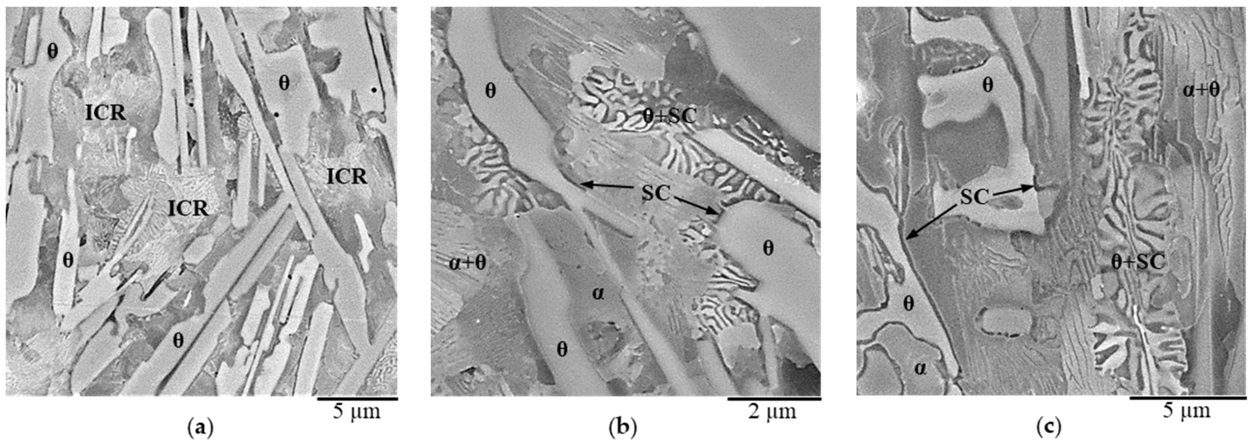
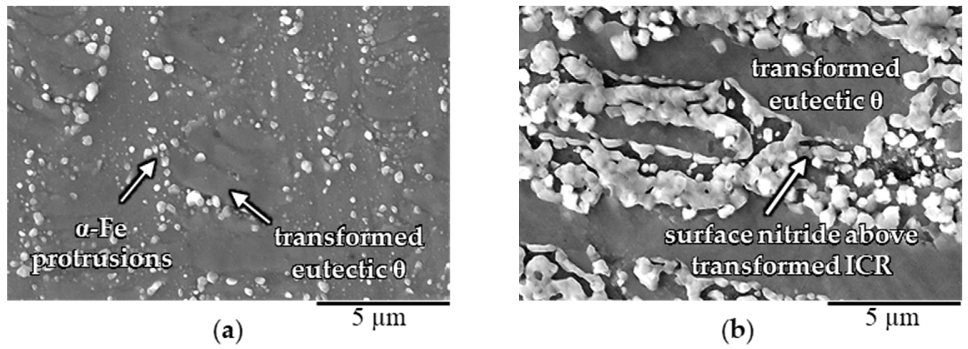
3.1. Characterization of the Initial White-Solidified Microstructures

As a result of the EBR, the graphite of the commercially available cast irons was dissolved up to a depth of about 1 mm [6]. White solidification occurred according to the metastable Fe-Fe3C system. The same applied to the model alloys after melting and rapid cooling. Independently of the alloy used, the microstructures exhibited coarse eutectic cementite plates, decomposed primary and eutectic austenite (γ-Fe) and some iron silicocarbide (SC) [17]. The SC typically formed along the eutectic cementite plates, and is known in the literature [18,19,20] as “Fe8Si2C” (also referred to as Fe23Si5C4, considering the actual elemental composition of the SC). The SC occurred in the white-solidified microstructures of all of the Si-containing alloys (i.e., the T and M alloys) irrespective of their chemical composition. Moreover, the SC occurred in a duplex structure consisting of alternating cementite and SC lamellae, and with a morphology different from the typical morphologies of the γ-Fe + θ eutectic and the α-Fe + θ eutectoid (pearlitic) cementite (cf. Figure 1). The EBSD analysis revealed that the duplex structure consisted of interwoven cementite θ and SC crystals [17].
In general, the austenite formed upon solidification was decomposed into ferrite and pearlite during cooling. In the case of the commercially available alloys, this resulted from preheating before the EBR. For most model alloys—except Fe-3.5C-3Si-Me—the upper critical cooling rate for martensite formation was too high due to the lack of alloying elements and was not reached during casting into the Cu mold. Additional alloying elements in Fe-3.5C-3Si-Me, such as Cu and/or Mn, shifted the upper critical cooling rate to lower values, so that austenite transformed into martensite under comparable casting conditions. For the following considerations on the nitriding mechanism of the remelted surface layers, it appeared to be largely irrelevant whether a pearlitic, ferritic or martensitic microstructure was present. Therefore, these regions are hereinafter referred to as intercarbidic regions (ICR) (see Figure 1).
The distribution of a substrate’s alloying elements (cf. Table 1) showed local heterogeneities within the white-solidified surface after the EBR. In accordance to the trends implied by the literature [21,22,23,24], the EDS examination revealed that the eutectic cementite of the ledeburite could be considered as basically Si- and Cu-free [6,11], while these elements were enriched in the pearlitic ICR. It should be noted that the latter statement refers primarily to the ferrite fraction of the pearlite, while the same is expected to apply for the eutectoid cementite in pearlite as to the eutectic cementite mentioned before. Due to the fine lamellar structure of the eutectoid cementite of the pearlite however, the elemental composition could not be resolved by the presently available EDS measurements. Mn was observed to enrich moderately in the eutectic cementite [11], also in line with the above-cited literature. Mn may also have been contained in the silicocarbides [25], a phenomenon not examined in this work.
During nitriding at 540 °C, macroscopic redistribution of the alloying elements Si, Cu and Mn did not occur, and their heterogenous distribution described in the last paragraph had a significant influence on both the nitriding mechanism as well as an effect. Extensive knowledge of the initial remelted microstructure is of great importance for their understanding.

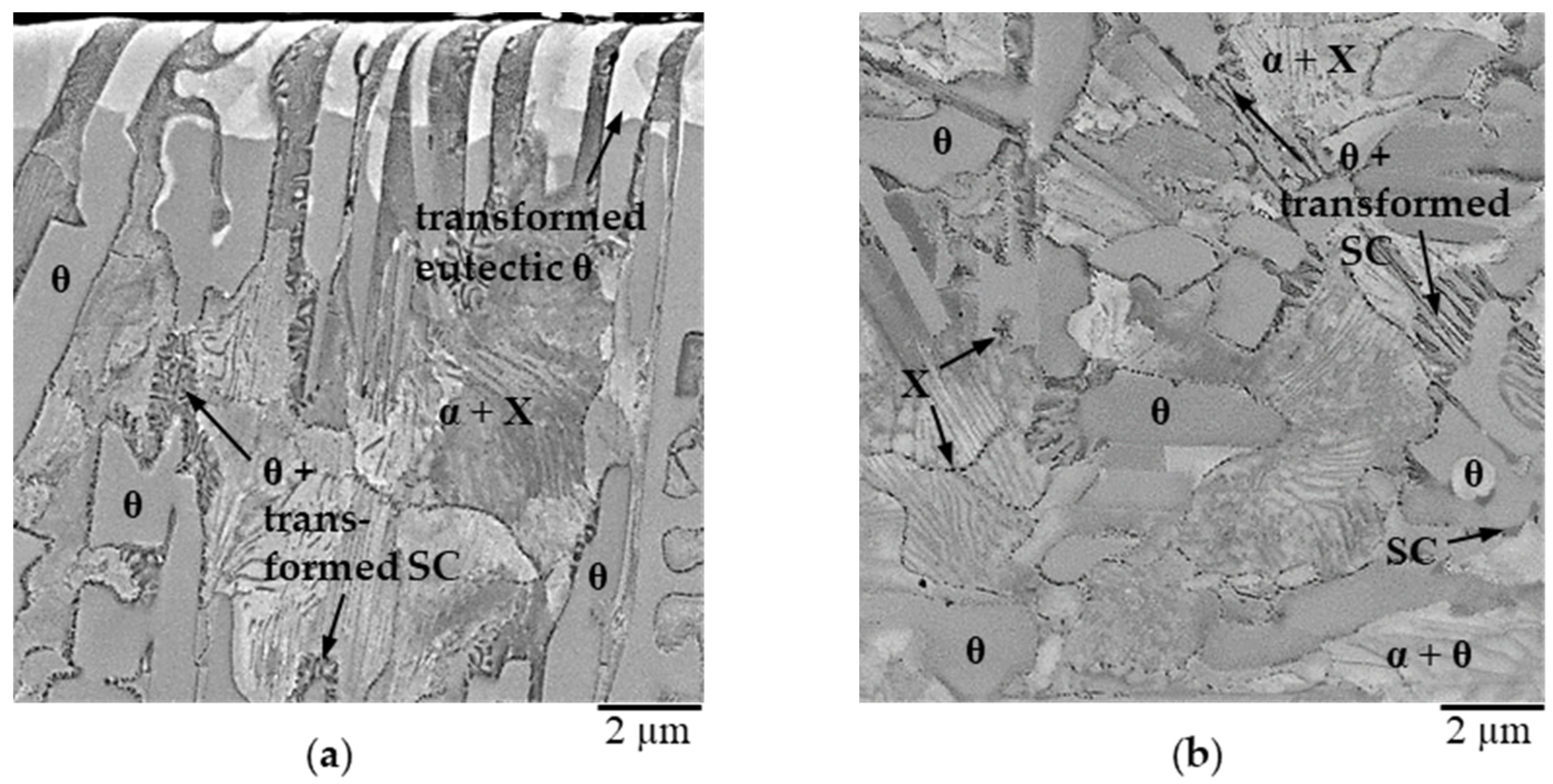
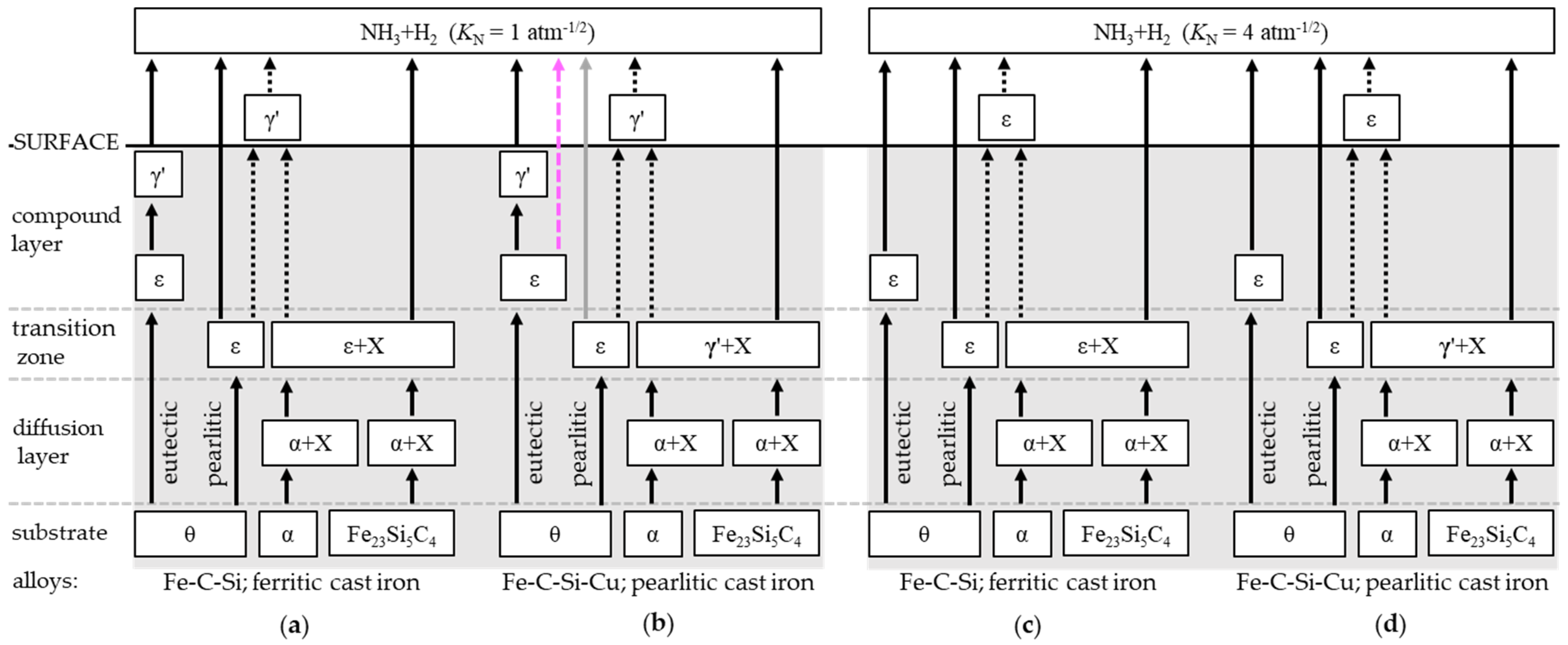
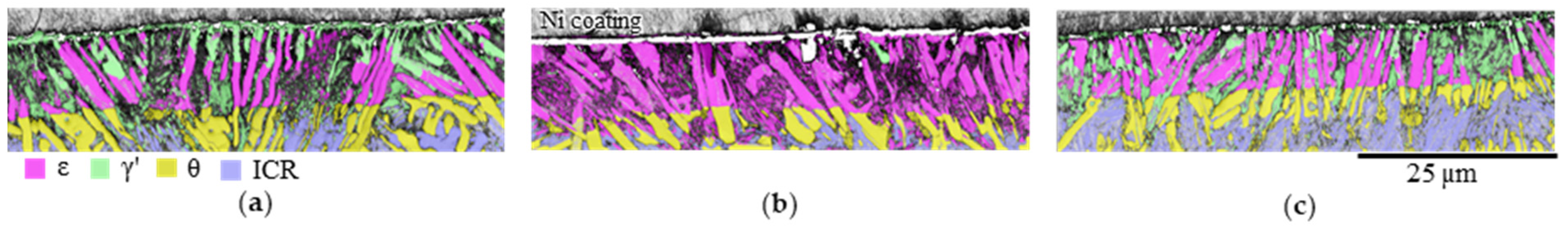
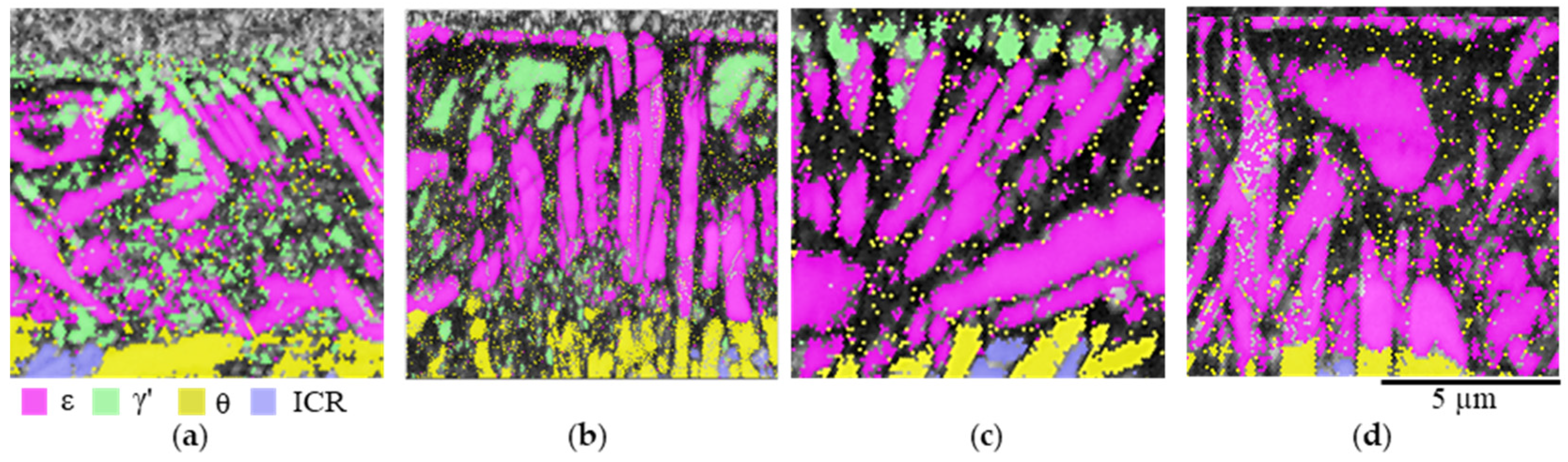
3.2. Nitriding Mechanism of White-Solidified Microstructures

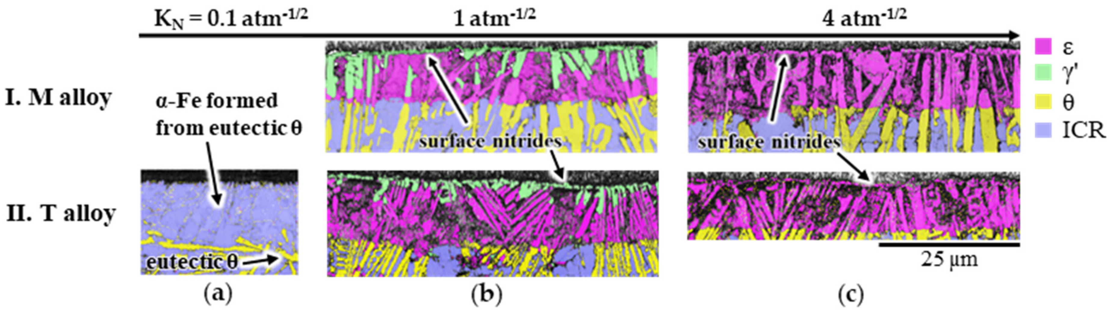
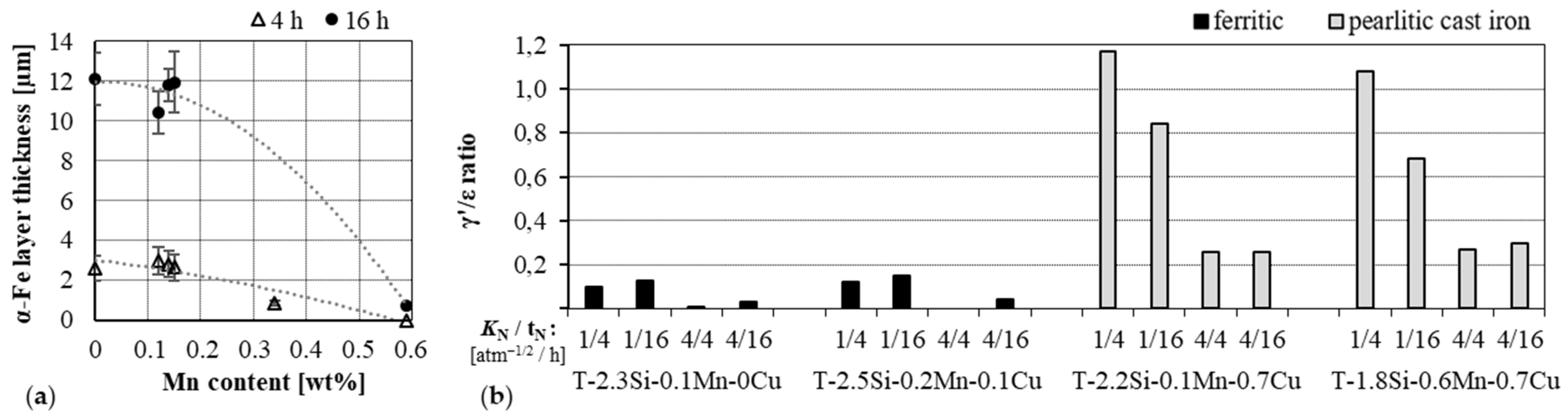
3.2.1. Influence of Silicon (Si)

In the following, the effect of different nitriding potentials KN on the nitriding behavior of Fe-C-Si model alloys as well as of the commercially available ferritic cast irons is discussed. The commercially available ferritic cast irons T-2.5Si-0.2Mn-0.1Cu and T-2.3Si-0.1Mn-0Cu exhibited comparable Si contents and only minor additions of Cu and Mn (see Table 1).
Due to the very slow diffusion rate of silicon at the applied nitriding temperature, the heterogeneous distribution of Si in the initial, white-solidified microstructures was retained during nitriding. Studies on compound layers in nitrided white-solidified Fe-C-Si alloys published in [16] show that the Si content of Fe nitride in formerly eutectic and pearlitic cementite is <0.02 at %, which is related to the low equilibrium solubility of Si in cementite, whereas ε nitride formed from Si-enriched α-Fe contained some Si.
In addition to the Fe nitrides, Si-rich nitrides and their precipitation kinetic played an important role in the growth of the compound and diffusion layer. Si is considered to be a “weak nitride former” [26] and it precipitates very slowly as nanosized amorphous nitride (Si3N4) in α-Fe [27,28,29,30]. Using BSE contrast in the SEM, the Si nitrides were distinguished as black, dot-like precipitates in the Si-enriched, non-carbide regions of the diffusion and compound layer (cf. Figure 2). Independently of the nitriding potential KN used, many small Si-nitride precipitates were formed near the surface (Figure 2a). With increasing distance from the surface, the number of precipitates decreased while their size increased (Figure 2b) [8,16,31]. Previous studies by Kante et al. [16] reveal that Fe-Si nitrides of the composition (Si3N4)1−x(Fe3N2)x, with x being in the order of 0.34–0.43, existed in the compound layer, referred to below as X. In Ref. [27], X was introduced as the amorphous iron siliconitride that occurs in the compound layer. The present authors believe that the amorphous “Si3N4” that develops upon precipitation in Si-containing α-Fe also contains Fe and corresponds to the same type of iron siliconitride, though with lower Fe content. Hence, all types of amorphous Si nitrides will be referred to as X.
The iron silicocarbide (SC) described above was unstable in contact with N, and decomposed into a phase mixture composed of α-Fe and X in a eutectoid fashion. In addition to this isothermal eutectoid reaction, which occurred in the diffusion layer, another eutectoid reaction occurred during compound layer growth; α-Fe transformed into ε nitride and X. During this eutectoid reaction, the Fe-Si nitrides (X) already formed in the diffusion layer were overgrown. Both eutectoid reactions are driven by a gradient in the chemical potential of N induced during nitriding and the external supply of N. Such reactions involve the cooperative growth of a crystalline phase (α-Fe/ε) and an amorphous Si-rich nitride (X).
The Fe carbonitrides γ’-Fe4(N, C) and ε-Fe3(N, C)1+x formed in the compound layer during nitriding with KN ≥ 1 atm−1/2 will be referred to below using simplified terms as Fe nitrides (γ’, ε). It was possible to assign the Fe nitrides detected by the EBSD measurements to the local microstructural constituents of the white-solidified substrates, since the former eutectic cementite and the ICR were still clearly visible in the compound layers even after nitriding.
At KN = 0.1 atm−1/2, no iron nitrides developed. The surface layer was decarburized in the near-surface region by the nitriding atmosphere, which led to the transformation of the eutectic cementite (θ) into α-Fe (Figure 2a and Figure 3a). Moreover, α-Fe protrusions grew on the material’s surface.
At KN = 1 atm−1/2, the Si-free eutectic cementite transformed into ε-Fe3(N, C)1+x first (cf. nitriding time of 1 h in Figure 4), which can be explained by the structural relationship between cementite and ε as well as by higher C solubility in ε than in γ’ [32]. With increasing nitriding time, the ε-nitride formed from the eutectic cementite transformed into γ’-Fe4(N, C) (cf. nitriding time of 16 h in Figure 4) as a consequence of the increasing release of ε-stabilizing carbon to the nitriding atmosphere upon nitriding under the “γ’-condition”. Therefore, γ’/ε double layers occurred in the formerly eutectic cementite (cf. nitriding time of 16 h in Figure 4). In contrast to the Si-free eutectic cementite, it was mainly ε-nitride that formed in the Si-enriched ICR. This suggested a greater stabilizing effect of Si on ε than on γ’. This ε-promoting effect was attributed to higher Si solubility in ε than in γ’ [30,33], but other reasons are also discussed in the literature [8,34]. It is worth noting however, that another recent work [9] suggests that, in nitriding Fe-Si alloys, Si can also have a γ’-promoting effect. The resolution of this apparent contradiction of the present results cannot be resolved at this time.
Furthermore, iron nitrides grew on the material surface (Figure 5b). These surface nitrides consisted exclusively of γ’ under the “γ’ condition” (cf. Figure 3b).
At KN = 4 atm−1/2, transformation of the ε formed from the eutectic cementite into γ’-nitride did not take place, so that even the formerly carbidic regions transformed exclusively into ε nitride. The ICR as well as the iron nitride formed on the surface consisted of ε-nitride (cf. Figure 3c).
The formation of α-Fe protrusions observed on top of the material surface at KN = 0.1 atm−1/2 (cf. Figure 5a)—and the formation of surface Fe nitrides observed at KN ≥ 1 atm−1/2 (cf. Figure 5b)—was attributed to the outward diffusion of Fe atoms to the surface during the nitriding treatment. The high interface density in the microstructure due to the presence of a large numerical density of nano-sized X precipitates occurring in the ICR promoted this outward diffusion. Therefore, the α-Fe protrusions as well as the Fe nitrides occurred preferentially above the ICR and above the decomposed SC. The driving force for such outward diffusion was the relaxation of the compressive stress that built up due to the N uptake. Similar phenomena were observed previously in the field of nitriding [35,36].
From the results presented, it appears that the nitriding mechanism—which has been investigated in depth on model alloys—also applies to remelted commercially available cast irons with a comparable elemental composition. The experimental results on the phase formation in the different regions of the nitrided layer (compound/diffusion layer) as a function of the different microstructural constituents (eutectic and eutectoid cementite, ferrite and silicocarbide) of the white-solidified Fe-C-Si model alloys and ferritic cast irons are summarized in Figure 6a for KN = 1 atm−1/2 and in Figure 6c for KN = 4 atm−1/2 after a nitriding time of 16 h. The different phase transformations occurring in different microstructural regions are a consequence of the inhomogeneous Si distribution in the white-solidified substrate materials, which remained unchanged at the micron scale during nitriding.

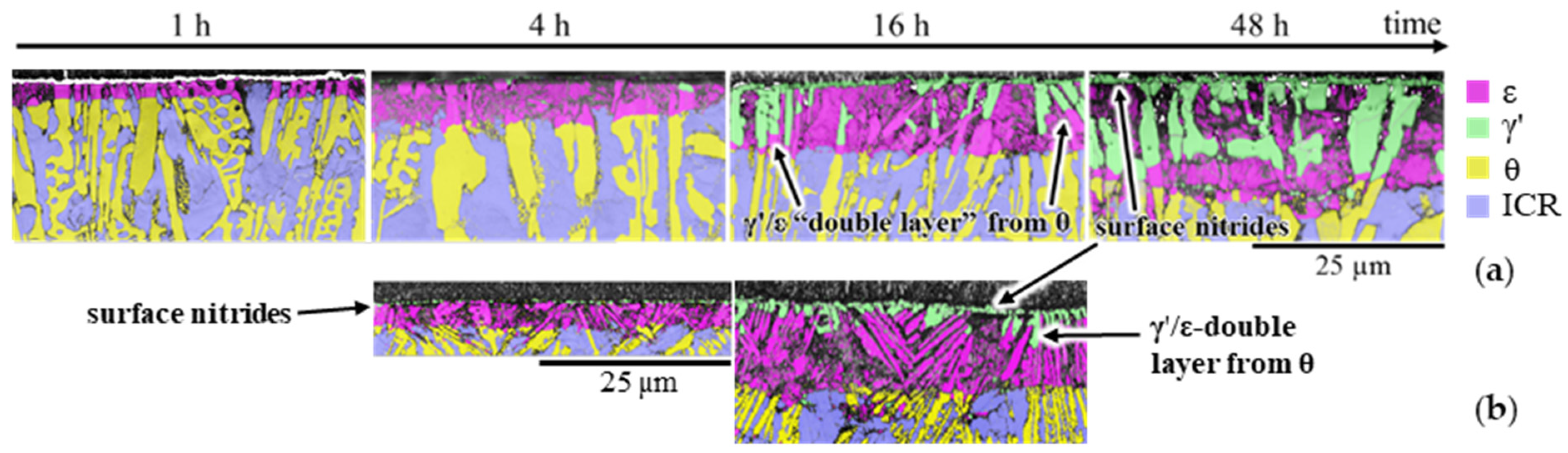
3.2.2. Influence of Manganese (Mn) and Copper (Cu)

Even small amounts (≤0.7 wt%) of Mn and/or Cu in the cast irons had a significant influence on the phase composition of the compound layer [31]. While Mn promoted the formation of ε-nitride, Cu supported the formation of γ’-nitride (Table 3). These effects could be reproduced on the model alloys with slightly higher contents of Mn (M-3.5C-3Si-1Mn) and Cu (M-3.5C-3Si-1Cu) (Figure 7a,b, Table 3) [11].
Mn appeared to stabilize ε formed from the Mn-containing eutectic cementite and, notably, to retard or hinder its transformation into γ’ at KN = 1 atm−1/2. An ε-promoting effect of Mn is already known from earlier works on C-free Fe-Mn alloys [9]. In the present case, the additional C might further enhance the effect of Mn, because the higher affinity of Mn to C, as compared to the affinity of Fe to C, also retards the decarburization that occurs during gas nitriding, i.e., Mn retards the loss of the ε-stabilizing C, as explicitly shown by the experiments at KN = 0.1 atm−1/2 (see below). Furthermore, Mn seemed to accelerate the precipitation of X in the ICR [11]. In [37], the solubility of Mn in Si-rich nitride precipitates—here referred to as X—was observed. The accelerated depletion of α-Fe by Si did not promote the formation of γ’. The ICR of the Fe-C-Si-Mn model alloy transformed into ε (see Figure 7b).
Cu did not seem to accelerate the precipitation of X in α-Fe [11]. The γ’-promoting effect of Cu can be attributed to the crystal structure of γ’ nitride, which likely allows for a partial substitution of Fe by Cu, suggesting a higher solubility of Cu in the γ’ than in the ε nitride [10]. The γ’-promoting effect of Cu exceeded the ε-promoting effect of Si (cf. Figure 8), i.e., in the presence of Cu in the alloys and even when nitrided at KN = 4 atm−1/2, the formation of γ’-nitride from Si-enriched α-Fe occurred in the ICR (cf. Figure 6b,d).
In the case of the simultaneous presence of Mn and Cu, there is a coupled effect (Figure 7c). The ICR transformed primarily into γ’ as a result of the copper enrichment. The transformation of ε into γ’ in the near-surface eutectic cementite at KN = 1 atm−1/2 and after longer nitriding times appeared to be retarded by the presence of Mn (cf. Figure 7c). Upon solidification, the Mn is enriched in the cementite, whereas Cu is enriched in the austenite/ICR. In agreement with the above discussion on Mn and Cu, the cementite transformed into persistent ε, whereas the ICR transformed into γ′ [11].
Investigations on surface decarburization during compound layer-free nitriding of white-solidified surface layers (KN = 0.1 atm−1/2) showed that the Mn tended to stabilize cementite against decarburization and, thus, hindered the transformation of the eutectic cementite into α-Fe (Figure 9a).
The different effects of the alloying elements—including with regard to their distribution in the microstructure—on the transformation of the microstructural constituents into the various nitrides can be quantified by means of the XRD analysis. The fractions of γ’ and ε in the compound layers after nitriding of the EB-remelted ferritic and pearlitic cast irons under γ’ and ε conditions for the different nitriding times are shown in Figure 9b. Compared to the phase composition of the compound layers on the remelted ferritic cast irons with no or only minor additions of Cu, the γ’-nitride was clearly predominant in the compound layers on the remelted Cu-containing pearlitic cast irons. This can be seen from the significantly higher γ’/ε ratio (Figure 9b).

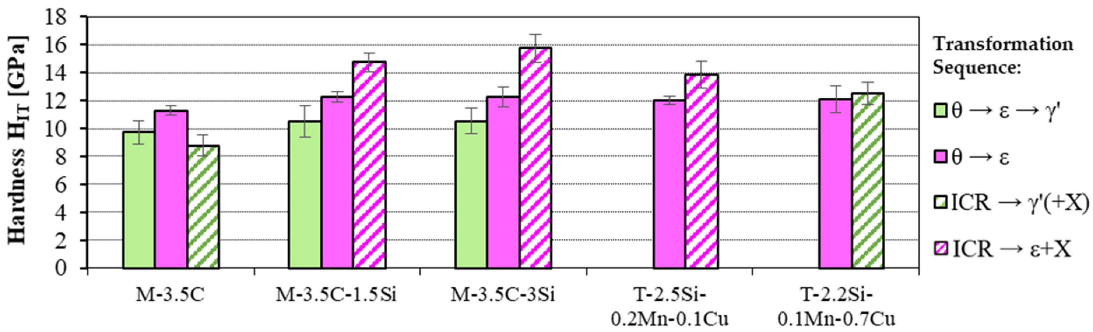
3.2.3. Influence of the Alloy Composition on the Hardness of the Compound Layer

The hardness of the compound layer was influenced by the nitride composition of that layer, which was particularly dependent on the type of alloying element contained in the white-solidified substrates, as shown above.
Nano-hardness measurements in Si-free compound layers showed that the hardness of ε-nitride was higher than that of γ’-nitride, which was likely due to the higher N + C content in ε (cf. Figure 10, alloy M-3.5C).
Separating the hardness values obtained from the transformed eutectic cementite (θ → ε and θ → ε → γ’) and the ICR (ferrite and pearlite) for the Si-containing alloys indicated that the ε- and γ’-nitrides formed from the eutectic cementite (Si-free), showing only a slight increase in hardness when compared to the Si-free model alloy. The hardness of the nitrides formed from what was previously the ICR was, in particular, influenced by their enrichment with Si. The γ’ formed in the ICR was strengthened by the Fe-Si nitride (X) particles. In the case of the pearlitic cast iron with Si and Cu (T-2.2Si-0.1Mn-0.7Cu), this resulted in a hardness increase of ΔHIT ≈ 3.7 GPa when compared to the γ’ in the Si-free model alloy (cf. Figure 10). As a result, the hardness differences within the two-phase (γ’, ε) compound layer of this Cu-containing pearlitic cast iron were small.
The X particles evidently also strengthened the ε-nitride formed in the presence of Si without the participation of Cu in the ICR. The hardness increase was dependent on the Si content and, in the case of the ferritic cast iron alloyed with 2.5 wt% Si (T-2.5Si-0.2Mn-0.1Cu), the hardness amounted to HIT ≈ 14 GPa, which was ΔHIT ≈ 1.9 GPa higher than the hardness of the ε-nitride formed from the Si-free eutectic cementite (cf. Figure 10).
In summary, the hardness of compound layers formed on Si-containing alloys was much higher than for a Si-free alloy. Furthermore, the hardness increase was affected by the initial microstructural constituents as well as by the type and amount of the nitride-forming elements.

4. Conclusions

Systematic studies on Fe-C, Fe-C-Si and Fe-C-Si-Me (Me = Cu, Mn, Mn + Cu) model alloys have elucidated the nitriding mechanism of ledeburitic surfaces layers in ferritic and pearlitic cast irons—as produced by electron beam remelting. The investigations showed that, in addition to the gas nitriding parameters (nitriding potential and nitriding time), the microstructural constituents of the white-solidified surface layer (eutectic cementite, iron silicocarbide, ferrite and pearlite) and the chemical composition of the alloys had a decisive influence on the phase composition of the compound layer. The high Si content present in the cast iron alloys was heterogeneously distributed in the white-solidified microstructure, which affected the nitride formation in the remelted ferritic cast irons as follows:
  • At least initially, Si-free eutectic cementite transformed completely to ε at KN ≥ 1 atm−1/2. At KN = 1 atm−1/2, longer nitriding times and Mn contents of <0.2 wt%, the already formed ε transformed into γ’ in the near-surface region. The hardness of this γ’ nitride formed from Si-free eutectic cementite was lower than that of the ε-nitride by ΔHIT ≈ 1.8 GPa.
  • Iron silicocarbide (SC), which typically formed along eutectic cementite plates, decomposed in the presence of nitrogen in the diffusion zone into α-Fe and X (X: Si-rich nitride precipitates). During compound layer growth, the α + X phase mixture formed from the SC transformed into ε and X.
  • In the intercarbidic, ferritic and pearlitic regions, silicon was enriched in α-Fe. The addition of nitrogen caused X to precipitate from α-Fe. As a result of the ε-promoting effect of the residual Si still dissolved in the α-Fe, the α-Fe transformed into ε. The lamellar Si-free pearlitic cementite transformed into ε. As a result of the Fe-Si nitrides X, the ε formed in the intercarbidic regions (ICR) exhibited a hardness that was higher by ΔHIT ≈ 1.9 GPa than the hardness of Si- and X-free ε formed from Si-free eutectic cementite.
  • During nitriding under the “γ’ condition” (KN = 1 atm−1/2), γ’ was formed on the surface and during nitriding under the “ε condition” (KN = 4 atm−1/2), ε-nitride was formed on the surface.
The alloying element Cu, which was additionally present in the pearlitic cast iron alloys and which, similar to Si, was enriched in α-Fe, altered the transformation behavior described in point three. Since the γ’-promoting effect of Cu surpassed the ε-promoting effect of Si, the α-Fe always transformed to γ’ at KN ≥ 1 atm−1/2. The hardness of the intercarbidic regions transformed into γ’ + X was lower than the ε + X phase mixture formed in the intercarbidic regions of the remelted ferritic cast irons. However, due to the Fe-Si nitride precipitates X that formed, the γ’-rich intercarbidic regions of the pearlitic cast irons had a hardness comparable to that of Si- and X-free ε (formed from eutectic cementite).
The Mn contents of ≥0.3 wt% sometimes present in pearlitic cast irons affect the transformation described in point one. The Mn enriched in the eutectic cementite stabilized the ε formed from that Mn-enriched cementite, retarding the carbon depletion of the near-surface regions and, thus, the transformation of the ε into γ’ at KN = 1 atm−1/2 during longer nitriding times. This effect may act in addition to the intrinsic stabilization of ε by Mn—even in the absence of C.
The findings presented in the present work provide a comprehensive understanding of the effects of both the alloying elements contained in the substrate materials, as well as the nitriding parameters on the structure of the nitrided layer, which facilitated improved tailoring of the combined surface treatment of cast irons by remelting and nitriding for particular use cases.

Author Contributions

Conceptualization, A.H. and S.K.; methodology, A.H. and S.K.; investigation, A.H. and S.K.; writing—original draft preparation, A.H.; writing—review and editing, A.B., A.H., S.K. and A.L.; visualization, A.H.; supervision, A.B. and A.L.; project administration, A.B. and A.L.; funding acquisition, A.B. and A.L. All authors have read and agreed to the published version of the manuscript.

Funding

This research was funded by the German Research Foundation (DFG), grant number BU 2568/7-2 and LE1403/1-2. The APC was funded by the Publication Fund of the TU Bergakademie Freiberg.

Data Availability Statement

Not applicable.

Acknowledgments

The authors wish to thank E. Siegismund (TU Bergakademie Freiberg, Institute of Materials Engineering) for conducting the nitriding experiments, and C. Schimpf (TU Bergakademie Freiberg, Institute of Materials Science) for his support in conducting the XRD measurements. The authors also wish to thank G. Bittner (TU Bergakademie Freiberg, Institute of Materials Engineering) for carrying out the nano-indentation hardness measurements.

Conflicts of Interest

The authors declare no conflict of interest. The funders had no role in the design of the study; in the collection, analysis, or interpretation of the data; in the writing of the manuscript; nor in the decision to publish the results.

References

  1. Spies, H.-J. Nitrieren und Nitrocarburieren, Gefüge—Eigenschaften—Kontrolliertes Nitrieren. HTM J. Heat Treatm. Mat. 2013, 68, 86–96. [Google Scholar] [CrossRef]
  2. Liedtke, D. Wärmebehandlung von Eisenwerkstoffen II, Nitrieren und Nitrocarburieren, 7th ed.; Expert Verlag: Tübingen, Germany, 2018. [Google Scholar]
  3. Buchwalder, A. Potenziale und Grenzen Kombinierter Randschichtbehandlungstechnologien in Verbindung Mit Einer Fest-/Flüssigphasen-Randschichtbehandlung Mittels Energiereicher Strahlverfahren für Gusseisenwerkstoffe, 1st ed.; Freiberger Forschungshefte, Werkstoffwissenschaft, B390; TU Bergakademie Freiberg: Freiberg, Germany, 2020. [Google Scholar]
  4. Buchwalder, A.; Spies, H.-J.; Klose, N.; Jung, A.; Zenker, R. Effects of Different Microstructural and Hardness Gradients Generated by Single and Combined Surface Treatments with a Nitriding Top Layer. In Proceedings of the 23rd IFHTSE Congress, Savannah, GA, USA, 18–21 April 2016. [Google Scholar]
  5. Kante, S.; Leineweber, A.; Holst, A.; Buchwalder, A. Low-temperature Annealing and Graphitizing of Low-alloy White Cast Irons Produced by Rapid Solidification Technique. Materialwiss. Werkstofftech. 2019, 50, 682–695. [Google Scholar] [CrossRef]
  6. Holst, A.; Buchwalder, A.; Hollmann, P.; Zenker, R. Influence of Cooling Rate on the Microstructural Features of a Remelted White-Solidified Cast Iron Surface and its Effects on Nitriding Behaviour. J. Mater. Process. Technol. 2019, 271, 377–383. [Google Scholar] [CrossRef]
  7. Kante, S. Microstructure and Nitriding of White-Solidified Fe–C–Si Alloys. Ph.D. Thesis, TU Bergakademie Freiberg, Freiberg, Germany, 2021. [Google Scholar]
  8. Kante, S.; Motylenko, M.; Leineweber, A. Nitriding of White-Solidified Fe–C–Si Alloys: Diffusion Path Concept Applied to Inhomogeneous Microstructures. Adv. Eng. Mater. 2022, 24, 2100833. [Google Scholar] [CrossRef]
  9. Meng, F.; Miyamoto, G.; Furuhara, T. Effects of Alloying Elements on Microstructure, Hardness and Growth Rate of Compound Layer in Gaseous-Nitrided Ferritic Alloys. Mater. Trans. 2021, 62, 596–602. [Google Scholar] [CrossRef]
  10. Leineweber, A.; Fischer, M.; Kante, S.; Martin, S. Effect of Cu on Nitriding of α-Fe. Metals 2022, 12, 619. [Google Scholar] [CrossRef]
  11. Kante, S.; Leineweber, A. Interaction of N with White-solidified Cast Iron Model Alloys: The Effect of Mn and Cu on the Formation of Fe and Si Nitrides. JCME 2021, 5, 66–70. [Google Scholar] [CrossRef]
  12. Buchwalder, A.; Zenker, R.; Rüthrich, K.; Nagel, K.; Griesbach, W.; Hartwig, S.; Siedler, J. Eine neue kombinierte Randschichttechnologie für hochbeanspruchte Gusseisenwerkstoffe. HTM J. Heat Treatm. Mat. 2014, 69, 138–147. [Google Scholar] [CrossRef]
  13. Lehrer, E. Über das Eisen-Wasserstoff-Ammoniak-Gleichgewicht. Z. Elektrochem. Angew. Phys. Chem. 1930, 36, 383–392. [Google Scholar]
  14. Bachmann, F.; Hielscher, R.; Schaeben, H. Texture Analysis with MTEX—Free and Open Source Software Toolbox. SSP 2010, 160, 63–68. [Google Scholar] [CrossRef] [Green Version]
  15. Krakow, R.; Bennett, R.J.; Johnstone, D.N.; Vukmanovic, Z.; Solano-Alvarez, W.; Lainé, S.J.; Einsle, J.F.; Midgley, P.A.; Rae, C.M.F.; Hielscher, R. On three-dimensional misorientation spaces. Proc. R. Soc. A 2017, 473, 20170274. [Google Scholar] [CrossRef] [PubMed]
  16. Kante, S.; Kürnsteiner, P.; Motylenko, M.; Gault, B.; Leineweber, A. Eutectoid growth of nanoscale amorphous Fe-Si nitride upon nitriding. Acta Mater. 2021, 209, 116774. [Google Scholar] [CrossRef]
  17. Kante, S.; Leineweber, A. The iron silicocarbide in cast irons revisited. J. Alloys Compd. 2020, 815, 152468. [Google Scholar] [CrossRef]
  18. Spinat, P.; Senateur, J.P.; Fruchart, R.; Herpin, P. Caractérisation des deux phases isotypes «Mn8Si2C» et «Fe8Si2C». C. R. Acad. Sci. Paris Sér. C 1972, 274, 1159–1162. [Google Scholar]
  19. Marles, D. The Carbides in Iron-Carbon-Silicon Alloys and Cast Irons. J. Iron Steel Inst. Lond. 1948, 158, 433–436. [Google Scholar]
  20. Malinochka, Y.N.; Osada, N.G.; Koval’chuk, G.Z. A new structural constituent in Fe-C-Si alloys. Met. Sci. Heat Treat. 1961, 3, 299–305. [Google Scholar] [CrossRef]
  21. Kagawa, A.; Okamoto, T. Coefficients for equilibrium partition of a third element between solid and liquid in iron-carbon base ternary alloys and their relation to graphitization during iron-carbon eutectic solidification. J. Mater. Sci. 1984, 19, 2306–2318. [Google Scholar] [CrossRef]
  22. Ande, C.K.; Sluiter, M.H.F. First-principles prediction of partitioning of alloying elements between cementite and ferrite. Acta Mater. 2010, 58, 6276–6281. [Google Scholar] [CrossRef]
  23. Bhadeshia, H.K.D.H. Cementite. Int. Mater. Rev. 2020, 65, 1–27. [Google Scholar] [CrossRef] [Green Version]
  24. Al-Salman, S.A.; Lorimer, G.W.; Ridley, N. Partitioning of silicon during pearlite growth in a eutectoid steel. Acta Metall. 1979, 27, 1391–1400. [Google Scholar] [CrossRef]
  25. Spinat, P.; Brouty, C.; Whuler, A.; Herpin, P. Etude Structurale de la Phase ‘Mn8Si2C’. Acta Crystallogr. 1975, B31, 541–547. [Google Scholar] [CrossRef]
  26. Steiner, T.; Mittemeijer, E.J. Alloying Element Nitride Development in Ferritic Fe-Based Materials Upon Nitriding: A Review. J. Mater. Eng. Perform. 2016, 25, 2091–2102. [Google Scholar] [CrossRef] [Green Version]
  27. Mittemeijer, E.J.; Biglari, M.H.; Böttger, A.J.; van der Pers, N.M.; Sloof, W.G.; Tichelaar, F.D. Amorphous precipitates in a crystalline matrix; precipitation of amorphous Si3N4 in α-Fe. Scr. Mater. 1999, 41, 625–630. [Google Scholar] [CrossRef]
  28. van Landeghem, H.P.; Gouné, M.; Bordère, S.; Danoix, F.; Redjaïmia, A. Competitive precipitation of amorphous and crystalline silicon nitride in ferrite: Interaction between structure, morphology, and stress relaxation. Acta Mater. 2015, 93, 218–234. [Google Scholar] [CrossRef]
  29. Meka, S.R.; Jung, K.S.; Bischoff, E.; Mittemeijer, E.J. Unusual precipitation of amorphous silicon nitride upon nitriding Fe–2at.%Si alloy. Philos. Mag. 2012, 92, 1435–1455. [Google Scholar] [CrossRef]
  30. Meka, S.R.; Mittemeijer, E.J. Abnormal nitride morphologies upon nitriding iron-based substrates. JOM 2013, 65, 769–775. [Google Scholar] [CrossRef]
  31. Holst, A.; Buchwalder, A.; Zenker, R. Influence of gas nitriding conditions on layer structure formation on grey- and white-solidified cast irons (part I). Metall. Ital. 2020, 112, 28–39. [Google Scholar]
  32. Kante, S.; Leineweber, A. Two-phase and three-phase crystallographic relationships in white-solidified and nitrided Fe-C-Si cast iron. Acta Mater. 2019, 170, 240–252. [Google Scholar] [CrossRef]
  33. Meka, S.R.; Schubert, A.; Bischoff, E.; Mittemeijer, E.J. Unusual Iron Nitride Formation Upon Nitriding Fe-Si Alloy. Metall. Mater. Trans. A 2020, 51, 3154–3166. [Google Scholar] [CrossRef] [Green Version]
  34. Kante, S.; Leineweber, A. Fe Nitride Formation in Fe–Si Alloys: Crystallographic and Thermodynamic Aspects. Metall. Mater. Trans. A 2021, 52, 4957–4973. [Google Scholar] [CrossRef]
  35. Spies, H.-J.; Biermann, H.; Fischer, A. Nitriding behaviour of the intermetallic alloy FeAl. Z. Metallkd. 2005, 96, 781–786. [Google Scholar] [CrossRef]
  36. Kodentsov, A.A.; van Dal, M.J.H.; Cserháti, C.; Daróczi, L.; van Loo, F.J.J. Permeation of Nitrogen in Solid Nickel and Deformation Phenomena Accompanying Internal Nitridation. Acta Mater. 1999, 47, 3169–3180. [Google Scholar] [CrossRef]
  37. Klemm-Toole, J.; Burnett, M.; Clarke, A.J.; Speer, J.G.; Findley, K.O. Influences of Vanadium and Silicon on Case Hardness and Residual Stress of Nitrided Medium Carbon Steels. Metall. Mater. Trans. A 2021, 52, 462–482. [Google Scholar] [CrossRef]
Figure 1. Cross-sectional SEM images (BSE contrast) of white-solidified (a,b) commercially available cast iron T-2.5Si-0.2Mn-0.1Cu, and (c) M-3.5C-3Si model alloy after EBR (θ—eutectic cementite, α—ferrite, α + θ—pearlite, SC—silicocarbide, ICR—intercarbidic regions, which include the microstructural components α, α + θ and SC). Both images are from nitrided specimens in a depth unaffected by the inward-diffusing N.
Metals 13 00156 g001
Figure 2. Cross-sectional SEM images (BSE contrast) of remelted T-2.5Si-0.2Mn-0.1Cu nitrided with KN = 0.1 at 540 °C for 4 h. Si nitride precipitations (X) in the intercarbidic regions are evident (a) near the decarburized surface and (b) at the end of the diffusion layer.
Metals 13 00156 g002
Figure 3. Cross-sectional EBSD phase maps of the compound layers of white-solidified (I) M-3.5C-3Si model alloy [8] and (II) commercially available ferritic cast iron T-2.5Si-0.2Mn-0.1Cu [31] nitrided at 540 °C for 16 h with (a) KN = 0.1 atm−1/2, (b) KN = 1 atm−1/2, and (c) KN = 4 atm−1/2.
Metals 13 00156 g003
Figure 4. Cross-sectional EBSD phase maps of the compound layers of white-solidified (a) M-3.5C-3Si model alloy [8] and (b) remelted commercially available T-2.5Si-0.2Mn-0.1Cu ferritic cast iron [8,31], nitrided at 540 °C for the indicated periods of time and at KN = 1 atm−1/2.
Metals 13 00156 g004
Figure 5. Top-surface SEM images (SE contrast) of remelted T-2.5Si-0.2Mn-0.1Cu after nitriding at 540 °C for 4 h with (a) KN = 0.1 atm−1/2, and (b) KN = 1 atm−1/2.
Metals 13 00156 g005
Figure 6. Schematic description of phase formation during nitriding (540 °C, 16 h) with (a,b) KN = 1 atm−1/2 and (c,d) KN = 4 atm−1/2 as a function of local microstructural constituents (θ—eutectic and pearlitic cementite, α—ferrite, Fe23Si5C4—silicocarbide) of white-solidified: (a,c) Fe-C-Si and ferritic cast iron alloys; (b,d) Fe-C-Si-Cu and pearlitic cast iron alloys with <0.2 wt% Mn. For pearlitic cast irons with ≥0.3 wt% Mn, the transformation ε → γ’ did not occur at KN = 1 atm−1/2 (see magenta arrow). The transformation of the ε formed from the pearlitic cementite into γ’ at KN = 1 atm−1/2 and 16 h could not be ruled out without doubt due to the fine structure (see gray arrow).
Metals 13 00156 g006
Figure 7. Cross-sectional EBSD phase maps of compound layers formed after nitriding at 540 °C for 16 h and KN = 1 atm−1/2 of Fe-3.5C-3Si-Me model alloys with: (a) 1 wt% Cu; (b) 1 wt% Mn; (c) 1 wt% Mn + 1 wt% Cu [11].
Metals 13 00156 g007
Figure 8. Cross-sectional EBSD phase maps of the compound layers formed after nitriding (540 °C, 16 h) with (a,c) KN = 1 atm−1/2 and (b,d) KN = 4 atm−1/2 on cast iron alloys: (a,b) T-2.2Si-0.1Mn-0.7Cu with Cu, and (c,d) T-2.5Si-0.2Mn-0.1Cu with hardly any Cu (individual yellow dots in the compound layer: mis-indexed cementite pixels).
Metals 13 00156 g008
Figure 9. Effect of alloying elements Mn and Cu in EB remelted cast iron materials after nitriding at 540 °C for the indicated times and (a) KN = 0.1 atm−1/2 (decarburization) on the thickness of the α-Fe layer measured by SEM (BSE contrast) on the transformed eutectic cementite (curves drawn as an orientation guide) and (b) indicated KN values on the γ’/ε ratio (calculated from XRD measurement data in wt%).
Metals 13 00156 g009
Figure 10. Influence of Si content and local initial microstructure (eutectic cementite θ and intercarbidic, ferritic-pearlitic regions in the ICR) on the hardness of the ε and γ’ phases formed from eutectic cementite, as well as of the γ’ phase (only M-3.5C) and of the ε + X and γ’ + X phase mixtures formed in the ICRs after nitriding (540 °C, 16 h, KN = 1 atm−1/2); hardness measurement with Fmax = 10 mN. For the commercially available cast iron alloys, the areas near the surface with eutectic cementite that transformed into γ’ (transformation sequence θ → ε → γ’) were too small for hardness measurements.
Metals 13 00156 g010
Table 1. Elemental composition (Fe-based) in wt% of the commercially available cast irons (T) and of the model alloys (M) investigated.
DesignationCSiMnCuPSMg
T-2.3Si-0.1Mn-0Cu3.722.320.12-0.0160.0090.04
T-2.5Si-0.2Mn-0.1Cu3.442.520.150.060.0110.009-
T-2.2Si-0.1Mn-0.7Cu3.512.180.140.730.0140.0090.03
T-2.3Si-0.3Mn-0.7Cu3.552.320.340.650.0240.0080.04
T-1.8Si-0.6Mn-0.7Cu 13.371.800.590.710.0430.008-
M-3.5C3.57<0.01-----
M-3.5C-1.5Si3.611.6-----
M-3.5C-3Si3.603.0-----
M-3.5C-3Si-1Mn3.612.650.86----
M-3.5C-3Si-1Cu3.582.98-0.87---
M-3.5C-3Si-1Mn-1Cu3.472.660.960.99---
1 To improve the remelting behavior, the cast iron material EN-GJL-250 was additionally alloyed with 0.17 wt% titanium [12].
Table 2. Crystal structure data used for indexing of EBSD patterns and to evaluate XRD patterns.
PhaseSpace GroupTypical Lattice Parameters
α-FeIm 3 ¯ ma = 2.87 Å
γ′-Fe4(N, C)Pm 3 ¯ ma = 3.79 Å
ε-Fe3(N, C)1+xP6322a = 4.72 Å, c = 4.42 Å
θ-Fe3C1−zPnmaa = 5.09 Å, b = 6.74 Å, c = 4.53 Å
Table 3. Qualitative estimation of phase composition within the compound layers as a function of microstructural constituents (eutectic cementite; intercarbidic regions ICR) and of surface nitrides for white-solidified commercially available cast iron (T) and model alloys (M), nitrided at 540 °C for 16 h at the indicated values of KN.
KN [atm−1/2]14
MicrostructureAlloyCementiteICRSurfaceCementiteICRSurface
Alloy
T-2.3Si-0.1Mn-0Cuγ′/εεγ′εεε
T-2.5Si-0.2Mn-0.1Cuγ′/ε(γ′+) εγ′εεε
T-2.2Si-0.1Mn-0.7Cuγ′/εγ′γ′εγ′ (+ε)ε
T-1.8Si-0.6Mn-0.7Cu(γ′)/εγ′γ′εγ′ (+ε)ε
M-3.5C-3Siγ′/εεγ′εεε
M-3.5C-3Si-1Mnεεγ′---
M-3.5C-3Si-1Cuγ′/εγ′γ′---
M-3.5C-3Si-1Mn-1Cu(γ′)/εγ′γ′---
Disclaimer/Publisher’s Note: The statements, opinions and data contained in all publications are solely those of the individual author(s) and contributor(s) and not of MDPI and/or the editor(s). MDPI and/or the editor(s) disclaim responsibility for any injury to people or property resulting from any ideas, methods, instructions or products referred to in the content.

