Article

Effect of the Pre-Shot Peening and Nitrogen Ion Implantation Combined Surface Treatments on the Surface Structure and Properties of Gear Steel 16Cr3NiWMoVNbE

1
AECC Beijing Institute of Aeronautical Materials, Beijing 100095, China
2
Aviation Key Laboratory of Advanced Corrosion and Protection on Aviation Materials, Beijing 100095, China
3
State Key Laboratory of Solid Lubrication, Lanzhou Institute of Chemical Physics, Chinese Academy of Sciences, Lanzhou 730000, China
*
Author to whom correspondence should be addressed.
Metals 2022, 12(9), 1509; https://doi.org/10.3390/met12091509
Submission received: 9 August 2022 / Revised: 9 September 2022 / Accepted: 9 September 2022 / Published: 13 September 2022
(This article belongs to the Special Issue Surface Strengthening of Engineering Materials)

Abstract

:
Transmission engineering components need to fulfill requirements for adequate wear resistance and fatigue resistance, which are related to their surface properties. In this paper, we combined shot peening and nitrogen ion implantation to improve the surface properties of 16Cr3NiWMoVNbE gear steel. The average surface roughness decreased slightly after the ion implantation because of the high-speed impact of implanted ions having the surface etching role. The maximum compressive residual stress of the near-surface layer after the surface treatment increased by more than 11.8–15.9% compared with shot peening. The nitrogen ions diffused through the peening deformation channel, and the deformation degree and the implantation temperature were positively correlated with the diffusion process. The surface nano-hardness obtained by ion implantation after shot peening was increased by 124.4% compared to the AR state.

1. Introduction

Certain industrial fields require the reliable service of transmission components. Gears, splines, and other structures should possess excellent fatigue and wear performance [1], but it is challenging to optimize their surface structure. Surface deformation strengthening is an important means to improve fatigue performance [2]. Shot peening [3] utilizes spherical media to impact the metal surface, and it introduces compressive residual stress, refines subgrains and increases surface hardness [4], which significantly improves fatigue performance. Still, there are only a few reports on the influence of shot peening on wear performance. In the ion implantation technology [5,6], ions are accelerated by an electric field toward the surface to produce a highly concentrated ion-rich film out of chemical equilibrium at a relatively low temperature [7]. However, ion implantation technology is more often applied in functional areas than in structural applications, such as wear resistance [8,9], because of its very shallow modified layer.
As well as a process method for nitrogen elements to enter the surface layer, ion nitriding is often used in combination with surface strengthening to increase the depth of the nitriding layer [10,11]. Kovaci et al. [12] investigated the shot peening pre-treatment on plasma nitriding, claimed that shot peening enhanced the nitrogen diffusion kinetics by enabling new diffusion paths. Research results from Tang et al. [13] showed that the nitride thickness had doubled after laser peening. These results make us realize that the application of surface mechanical treatment can make nitrogen atoms enter the surface lattice faster and deeper, which may improve the problem of small ion implantation layer depth.
Therefore, we have studied the surface treatment that assumes pre-shot peening followed by nitrogen ion implantation for the simultaneous enhancement of fatigue and wear resistance. A variety of surface layer analysis methods were used to characterize the combined modified layer, and the impact of shot peening and ion implantation modification on the surface layer performance affecting fatigue and wear properties was analyzed.

2. Experimental Set-Up

2.1. Materials

The research material is gear steel 16Cr3NiWMoVNbE (16Cr3). Take samples from forged bars of this material and process them into rectangles of 7 mm × 7 mm × 15 mm. The chemical composition and mechanical properties are shown in Table 1 and Table 2, respectively.

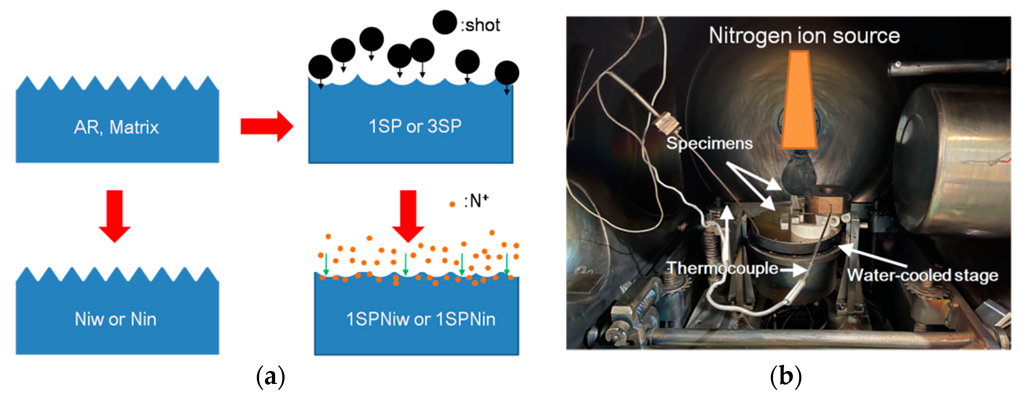
2.2. Shot Peening and Ion Implanataion

Herein, we introduced four sample groups to study the interaction between shot peening and ion implantation of gear steel 16Cr3: (1) grinding (AR); (2) shot peening after grinding (xSP); (3) nitrogen ion implantation after grinding (NIy); (4) shot peening and nitrogen ion implantation after grinding (xSPNIy) as shown in Figure 1a, where x and y represent the parameters of shot peening and ion implantation processes, respectively. The influence of the surface plastic deformation was studied by changing two shot peening parameters of ASH230 shots/0.3 mmA and AZB150 beads/0.1 mmA, indicating that x = 3 or 1. In addition, the ion bombardment in the implantation process will induce heating of the metal surface. Based on the implantation voltage of 60 kV, the effect of surface temperature on the surface structure was analyzed by comparing two processes: water cooling (53 °C) and non-water cooling (200 °C), as shown in Figure 1b, indicating that y = w or n. The processing parameters are shown in Table 3.

2.3. Characterization Techniques

Surface morphology was measured using ZYGO NEWVIEW white light interferometer (ZYGO, Middlefield, CT, USA) with 10 times magnification. PROTO LXRD X-ray diffractometer (PROTO, Taylor, MI, USA) was applied to obtain residual stress profiles along the depth direction. The surface material is peeled off layer by layer by electropolishing using saturated brine at room temperature, and the target material, tube voltage and tube current are CrKα, 20 kV and 20 mA, respectively. The JSM JEOL 7001F scanning electron microscope (JEOL, Tokyo, Japan) equipped with an Oxford Nordlynano electron backscatter diffraction (EBSD) (Carl Zeiss AG, Oberkochen, Germany) accessory was used to observe the cross-sectional structure after different surface treatments. The surface structure was observed using JSM JEOL-2010F field emission transmission electron microscope (JEOL, Tokyo, Japan) and Zeiss Auriga focused ion beam. Nano-hardness was measured using an NHT-2 nanoindentation (CSM, Aargau, Switzerland) with a Berkovich indenter.

3. Results and Discussion

3.1. Surface Morphology

From the three-dimensional topography picture shown as Figure 2, after shot peening, the fine tool marks that were originally ground are replaced by dense craters. However, ion implantation has little effect on the overall surface morphology. The average surface roughness, Ra, and the peak-to-valley height, Rz, are shown in Figure 2, Figure 3 and Table 4. The roughness of the AR state is about Ra 0.631 μm, and the roughness of the NIw and NIn states is less than that of AR, Ra 0.296 μm and Ra 0.340 μm, respectively. The roughness of the 1SP and 3SP states is significantly increased, reaching Ra 1.609 μm and Ra 4.809 μm, respectively. The average surface roughness of the 1SPNIw and 1SPNIn states is also slightly lower than before the ion implantation, Ra 1.363 μm and Ra 1.379 μm, respectively. At the same time, it is worth noting that after ion implantation, the peak-to-valley height Rz is also significantly reduced. The peak-to-valley height of AR state is Rz 9.808 μm; after implantation, it is Rz 2.869–2.997 μm, while the peak-to-valley height of 1SP state is Rz 16.222 μm; after implantation, it is Rz 11.201–13.061 μm. The results show that shot peening has the strongest effect on surface roughness. The Ra and Rz increases with the shot peening intensity, and apparent crater marks appear on the surface; ion implantation has a little effect on the roughness, which is manifested as a slight decrease in Ra and a significant decrease in Rz after the nitrogen ion implantation.
The shot peening increases the average surface roughness after grinding, which agrees with the previous results [14]. The ion implantation assumes the bombardment of the surface with ions accelerated by a high-voltage electric field. The size of nitrogen ions is significantly smaller than the contour fluctuations of grinding or shot peening [15], and the ion bombardment nearly represents an ion-etching process [16]. Therefore, the surface fluctuations decrease by ion etching independent of whether the surface is shot-peened or ground, and the surface roughness is reduced after ion implantation. Rz is expressed as the difference between the highest point and the lowest point of the contour line. Then, the highest point of the contour line is eroded by the largest density of ions. Therefore, after ion implantation, Rz is significantly reduced.

3.2. Residual Stress Profile

The residual stress profiles are shown in Figure 4. The surface residual stress and the compressive residual stress field depth (residual stress greater than −100 MPa) in the AR state reach (−252 MPa, 18 μm). After shot peening, residual compressive stress field was introduced on the surface of 16Cr3 gear steel. The higher the shot peening intensity, the lower the surface residual stress value and the greater the depth of the compressive residual stress. The surface residual stress and the compressive residual stress field depth in the 1SP and 3SP states reach (−611 MPa, 178 μm) and (−567 MPa, 290 μm), respectively. Regarding the NIw and NIn states, under the same sample state and the same voltage, the higher the ion implantation temperature, the greater the value of the compressive residual stress on the sample surface after the ion implantation. When the shot peening state is ion-implanted, the maximum compressive residual stress value of the 1SPNIw and 1SPNIn states is increased by 11.8% and 15.9% compared with the 1SP state, respectively.
The compressive residual stress of shot peening originates from the surface tensile elastoplastic deformation caused by the impact of the shot. In our research, the compressive residual stress of the original shot peening is further increased after ion implantation. Kovac et al. [11] and Unal et al. [12] proposed that the plastic deformation of shot peening could provide diffusion channels and accelerate the diffusion of nitrogen ions during nitriding. In this study, the implanted nitrogen atoms are faster than in ion nitriding so that the implanted ions can better utilize the deformation diffusion channels than ion nitriding, which relies on the concentration gradient diffusion. The embedded nitrogen atoms may yield lattice distortion and introduce the second type of internal stress, increasing the compressive residual stress value. Our results also show the residual stress influence layer upon ion implantation increases with the shot peening intensity and ion implantation temperature in terms of the specific process effect.

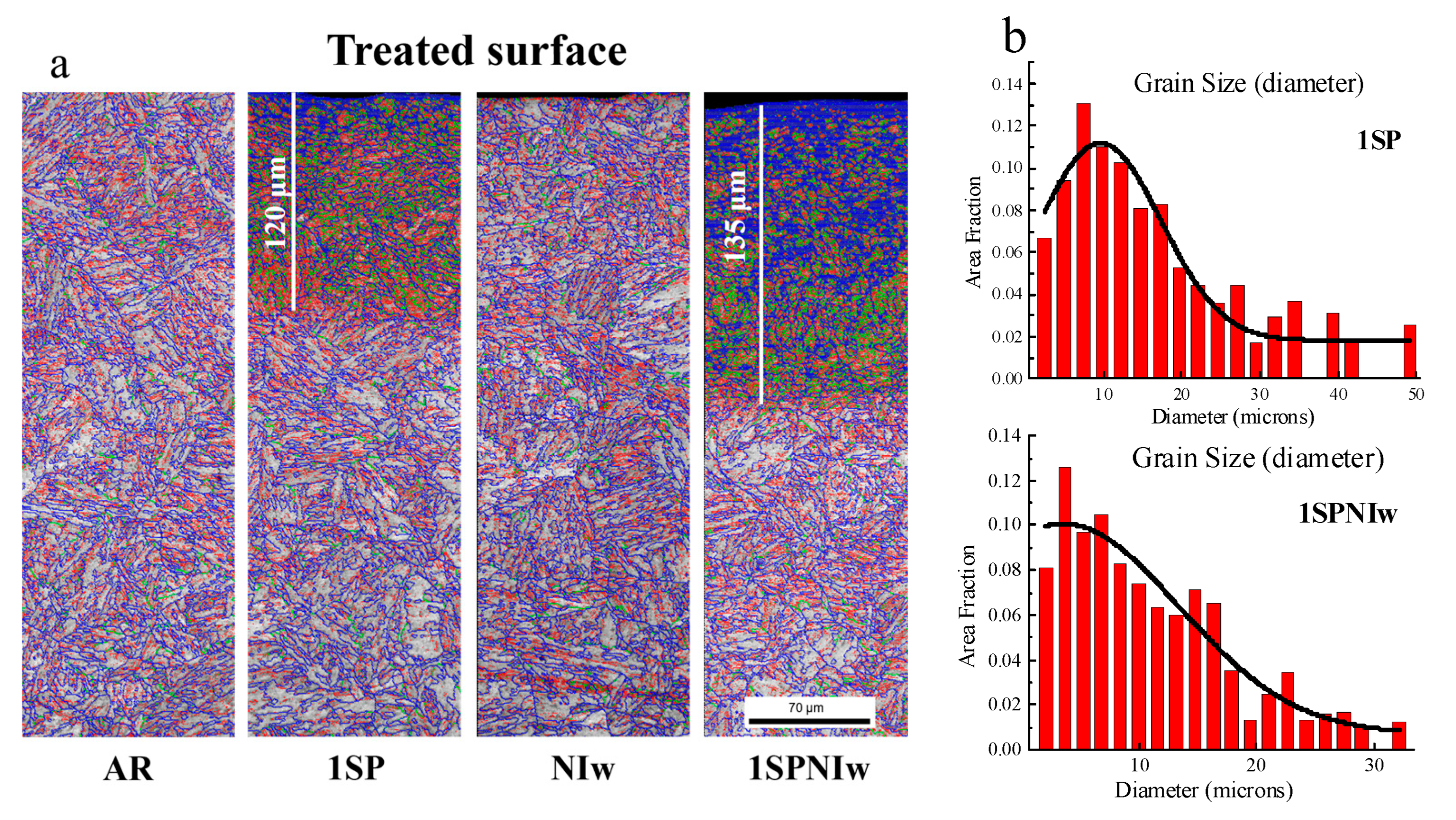
3.3. Surface Structure
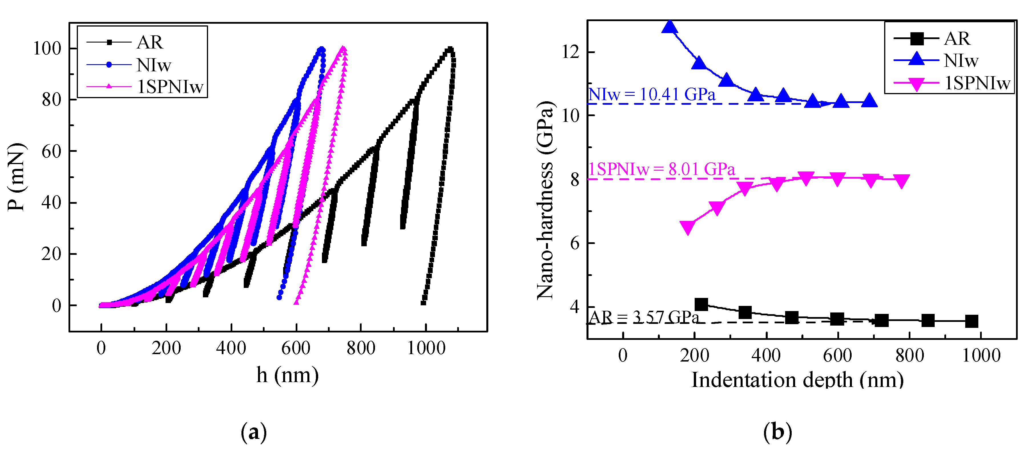
The examination of the microstructural cross-section (Figure 5a) shows that the ion implantation has little effect on the microstructure compared with the AR state. However, a structural refinement layer with a depth of 120 μm appears on the surface of the 1SP state, and the density of large-angle and small-angle grain boundaries significantly increases. After shot peening and nitrogen ion implantation, the density of large-angle grain boundaries (larger than 15°) increases, while the depth slightly increases from 120 μm to 135 μm. Besides, after shot peening and ion implantation, the subgrain size is smaller than after shot peening only, i.e., it is reduced from 9 μm to 4 μm corresponding to the maximum fraction, as shown in Figure 5b.
In order to study the effect of ion implantation, the microstructure of the sample along the depth direction was observed. Figure 6 shows bright-field TEM images of nitrogen ion implantation, shot peening, and shot peening following with nitrogen ion implantation samples. There is a grain refinement layer with a thickness of 1.5 μm on the surface of the ion implanted sample. After compounding with shot peening, the grain refinement layer increases from 1.5 μm to 3.1 μm, and the grain size is smaller, which is consistent with the results of the EBSD analysis.

3.4. Nano-Hardness

The Oliver and Pharr method and partial unloading mode were applied to obtain stable surface nano-hardness, Figure 7. The surface nano-hardness of the 1SPNIw (8.01 GPa), and NIw (10.41 GPa) states is increased by 124.4%, and 191.6%, respectively, compared with the AR state (3.57 GPa). The nano-hardness obtained by ion implantation after shot peening is less than that obtained by ion implantation after grinding under the same implantation dose, indicating that the increase in the shot peening intensity and implantation temperature would facilitate the diffusion of nitrogen atoms into the interior and that the high-density plastic deformation layer produced by shot peening promotes the diffusion of nitrogen atoms.
After the combined surface treatment of ion implantation and shot peening, the average surface roughness decreases, reducing the surface stress concentration factor [13]; the compressive residual stress near the surface increases, alleviating the externally loaded tensile stress [14,15]. These two effects improve fatigue performance and have practical engineering significance [16]. Based on the shot peening deformation, the ion implantation layer is deeper, and the hardness is more than twice higher than that of the original state, which effectively improves the hardness of the surface layer and enhances the wear resistance [17]. Thus, the combined mechanical and ion implantation surface treatments may improve the fatigue and wear performance of the gear component. However, the influence of the combined surface treatment method on fatigue and wear performance, and the process optimization and part adaptability, need to be further investigated.

4. Conclusions

Herein, the influence of pre-shot peening and ion implantation on the surface integrity of 16Cr3 gear steel was investigated based on the experimental results of surface morphology, roughness, residual stress, surface microstructure and nano-hardness indentation analysis. The main findings are as follows:
i.
After shot peening, the surface roughness of 16Cr3 gear steel increases significantly, and the surface roughness value increases with the growth of shot peening intensity. After nitrogen ion implantation, whether the surface is grinded or shot peened, the surface roughness decreases.
ii.
Under the same sample state and the same voltage, the higher the ion implantation temperature, the greater the residual compressive stress on the sample surface after ion implantation. The plastic deformation caused by shot peening provides a diffusion channel for ion implantation and accelerates the diffusion of nitrogen ion. The residual stress-affected layer during ion implantation increases with the increase in shot peening intensity and ion implantation temperature.
iii.
After shot peening, the surface layer of 16Cr3 gear steel produces a deformed layer of 120 μm, while the surface deformation layer increases to 135 μm, and the maximum percentage of the corresponding subgrain size decreases from 9 μm to 4 μm, after the combined peening and ion implantation treatment.
iv.
Compared with the AR state, the surface nano-hardness of the 1SPNIw and NIw states is increased by 124.4% and 191.6%, respectively. The diffusion channel effect of shot peening reduces the concentration of nitrogen ions on the surface, so that the hardness of the shot-peened and ion-implanted sample is smaller than that of the single ion-implanted sample.

Author Contributions

Conceptualization, X.W.; methodology, B.Z. and C.X.; formal analysis, Z.T.; writing—original draft preparation, C.X. and X.L.; supervision, S.D. All authors have read and agreed to the published version of the manuscript.

Funding

This research was funded by National Science and Technology Project of China (J2019-VII-0015-0155).

Institutional Review Board Statement

Not applicable.

Informed Consent Statement

Not applicable.

Data Availability Statement

Not applicable.

Conflicts of Interest

The authors declare no conflict of interest.

References

  1. Morales-Espejel, G.E.; Rycerz, P.; Kadiric, A. Prediction of micropitting damage in gear teeth contacts considering the concurrent effects of surface fatigue and mild wear. Wear 2018, 398–399, 99–115. [Google Scholar] [CrossRef]
  2. Thomas, M.; Jackson, M. The role of temperature and alloy chemistry on subsurface deformation mechanisms during shot peening of titanium alloys. Scr. Mater. 2012, 66, 1065–1068. [Google Scholar] [CrossRef]
  3. Liu, G.; Wang, S.C.; Lou, X.F.; Lu, J.; Lu, K. Low carbon steel with nanostructured surface layer induced by high-energy shot peening. Scr. Mater. 2001, 44, 1791–1795. [Google Scholar] [CrossRef]
  4. Li, W.L.; Fei, W.D.; Hanabusa, T. Effect of deposition condition on residual stress of iron nitride thin films prepared by magnetron sputtering and ion implantation. Appl. Surf. Sci. 2006, 252, 2847–2852. [Google Scholar] [CrossRef]
  5. Panepinto, A.; Cossement, D.; Snyders, R. Experimental and theoretical study of the synthesis of N-doped TiO2 by N ion implantation of TiO2 thin films. Appl. Surf. Sci. 2021, 541, 148493. [Google Scholar] [CrossRef]
  6. Oka, Y.; Kirinuki, M.; Nishimura, Y.; Azuma, K.; Fujiwara, E.; Yatsuzuka, M. Measurement of residual stress in DLC films prepared by plasma-based ion implantation and deposition. Surf. Coat. Technol. 2004, 186, 141–145. [Google Scholar] [CrossRef]
  7. Liu, H.J.; Leng, Y.X.; Tang, J.L.; Wang, S.; Xie, D.; Sun, H.; Huang, N. Tribological performance of ultra-high-molecular-weight polyethylene sliding against DLC-coated and nitrogen ion implanted CoCrMo alloy measured in a hip joint simulator. Surf. Coat. Technol. 2012, 206, 4907–4914. [Google Scholar] [CrossRef]
  8. Lin, Q.J.; Liu, H.J.; Zhu, C.C.; Chen, D.F.; Zhou, S.S. Effects of different shot peening parameters on residual stress, surface roughness and cell size. Surf. Coat. Technol. 2020, 398, 126054. [Google Scholar] [CrossRef]
  9. Jiang, S.Q.; Ma, X.X.; Sun, Y.; Sun, M.R. Corrosion behavior of AISI302 steel treated by elevated temperature nitrogen plasma immersion ion implantation. Scr. Mater. 2005, 53, 1427–1432. [Google Scholar] [CrossRef]
  10. Chkhalo, N.I.; Mikhailenko, M.S.; Mil’kov, A.V.; Pestov, A.E.; Polkovnikov, V.N.; Salashchenko, N.N.; Strulya, I.L.; Zorina, M.V.; Zuev, S.Y. Effect of ion beam etching on the surface roughness of bare and silicon covered beryllium films. Surf. Coat. Technol. 2017, 311, 351–356. [Google Scholar] [CrossRef]
  11. Kovaci, H.; Hacısalihoğlu, İ.; Yetim, A.F.; Çelik, A. Effects of shot peening pre-treatment and plasma nitriding parameters on the structural, mechanical and tribological properties of AISI 4140 low-alloy steel. Surf. Coat. Technol. 2019, 358, 256–265. [Google Scholar] [CrossRef]
  12. Unal, O.; Maleki, E.; Varol, R. Effect of severe shot peening and ultra-low temperature plasma nitriding on Ti-6Al-4V alloy. Vacuum 2018, 150, 69–78. [Google Scholar] [CrossRef]
  13. Li, J.K.; Yao, M.; Wang, D.; Wang, R.Z. An analysis of stress concentrations caused by shot peening and its application in predicting fatigue strength. Fat. Frac. Eng. Mat. Struc. 1992, 12, 1271–1279. [Google Scholar] [CrossRef]
  14. John, R.; Buchanan, D.J.; Jha, S.K.; Larsen, J.M. Stability of shot-peen residual stresses in an α + β titanium alloy. Scr. Mater. 2009, 61, 343–346. [Google Scholar] [CrossRef]
  15. Gao, Y.K.; Wu, X.R. Experimental investigation and fatigue life prediction for 7475-T7351 aluminum alloy with and without shot peening-induced residual stresses. Acta Mater. 2011, 59, 3737–3747. [Google Scholar] [CrossRef]
  16. Zhang, P.; Lindemann, J. Influence of shot peening on high cycle fatigue properties of the high-strength wrought magnesium alloy AZ80. Scr. Mater. 2005, 52, 485–490. [Google Scholar] [CrossRef]
  17. Hu, Y.; Watson, M.; Maiorino, M.; Zhou, L.; Wang, W.J.; Ding, H.H.; Lewis, R.; Meli, E.; Rindi, A.; Liu, Q.Y.; et al. Experimental study on wear properties of wheel and rail materials with different hardness values. Wear. 2021, 477, 203831. [Google Scholar] [CrossRef]
Figure 1. The shot peening and ion implantation number (a) and ion implantation procedure (b).
Metals 12 01509 g001
Figure 2. The 3-D topography after grinding, shot peening, and ion implantation: (a) AR; (b) 1SP; (c) 1SPNIw; (d) 1SPNIn; (e) 3SP; (f) NIw; (g) NIn.
Metals 12 01509 g002
Figure 3. The average surface roughness Ra range after grinding, shot peening, and ion implantation.
Metals 12 01509 g003
Figure 4. Residual stress field after grinding, shot peening, and ion implantation: (a) the residual profile at 0~300 μm range of the depth; (b) the residual profile at 0~50 μm range of the depth.
Metals 12 01509 g004
Figure 5. The microstructure after grinding, shot peening, and ion implantation. (a) Grain boundary rotation angle as determined by cross-sectional EBSD. The colors in the figure represent the grain boundary rotation angles, in which blue, green and red represent large (above 15°), medium (5° to 15°) and small (below 5°) rotation angles. (b) the fraction distribution of the subgrain size in the 1SP and 1SPNIw states.
Metals 12 01509 g005
Figure 6. Surface structure after shot peening and nitrogen ion implantation observed by FIB + TEM. The surface structure after nitrogen ion implantation (a), shot peening (b), and shot peening followed by nitrogen ion implantation (c).
Metals 12 01509 g006
Figure 7. The nano-hardness profile after grinding, nitrogen ion implantation and nitrogen ion implantation after shot peening: (a) Load-displacement (P-h) relations and(b) Hardness-displacement (H-h) relations.
Metals 12 01509 g007
Table 1. The chemical composition of gear steel 16Cr3NiWMoVNbE (wt%).
CMnSiWCrNiMoVFeC
0.160.580.811.142.811.250.480.45Bal.0.16
Table 2. The mechanical properties of gear steel 16Cr3NiWMoVNbE.
Temperature (°C)Rm (MPa)Rp0.2 (MPa)A (%)Z (%)
25140011901462
Table 3. The processing parameters of the combined surface treatment.
No.1. Shot Peening2. Nitrogen Ion Implantation
ASH230 Shots (0.3 mmA)AZB150 Beads (0.1 mmA)Water Cooling (53 °C)Non-Water Cooling (200 °C)
AR××××
1SP×××
1SPNIw××
1SPNIn××
3SP×××
NIw×××
NIn×××
Table 4. Surface roughness Rz after grinding, shot peening and ion implantation.
No.AR1SP1SPNIw1SPNIn3SPNIwNIn
Ra0.6311.6091.3631.3794.8090.2960.340
Rz9.80816.22211.20113.06132.1932.8692.997
Publisher’s Note: MDPI stays neutral with regard to jurisdictional claims in published maps and institutional affiliations.

