Article

Effect of Laser Shock Peening on High-Cycle Fatigue Performance of 1Cr18Ni9Ti/GH1140 Weld

1
Science and Technology on Plasma Dynamics Laboratory, Air Force Engineering University, Xi’an 710038, China
2
Tribology Research Institute, Key Laboratory of Advanced Technologies of Materials, Southwest Jiaotong University, Chengdu 610031, China
*
Author to whom correspondence should be addressed.
Metals 2022, 12(9), 1495; https://doi.org/10.3390/met12091495
Submission received: 1 August 2022 / Revised: 31 August 2022 / Accepted: 6 September 2022 / Published: 9 September 2022
(This article belongs to the Special Issue Laser Materials Processing Technology)

Abstract

:
The welded joints of 1Cr18Ni9Ti austenitic stainless steel and GH1140 nickel-based superalloy dissimilar materials used in certain types of aero-engine combustion liner components are prone to crack initiation during service, seriously affecting the service life of the combustion liner. In this study, laser shock peening (LSP) was applied to the dissimilar metal weld of 1Cr18Ni9Ti and GH1140, which are used in the combustion liner parts of aero engines. The effects of LSP on the residual stress, microhardness, microstructure and high-cycle fatigue performance of the weld were analyzed. The results show that the residual stress in the weld and heat-affected zones was converted from tensile residual stress to high amplitude compressive residual stress via LSP. Furthermore, the surface hardness of every region of the combustion liner weld was increased, especially in the weld zone, where an increase of 41.4% from 162 HV to 229 HV was observed. Simultaneously, with the introduction of grain refinement, gradient plastic deformation in the depth direction and the dislocation structure of the surface material, the high-cycle fatigue limit of the weld specimen was significantly increased and the fatigue limit of the 1Cr18Ni9Ti/GH1140 welded joint was improved by 65.39%, from 289 to 478 MPa.

1. Introduction

The welding of dissimilar metals not only satisfies the service conditions of equipment but also minimizes the use of expensive materials, thereby saving significant costs [1]. Nickel-based superalloys and austenitic stainless steel are widely used in the nuclear, power and aerospace industries due to their excellent resistance to high temperatures and corrosive atmospheres [2,3,4]. The welded joints of 1Cr18Ni9Ti austenitic stainless steel and GH1140 nickel-based superalloy dissimilar materials used in certain types of aero-engine combustion liner components are prone to crack initiation during service, seriously affecting the service life of the combustion liner. There are two main factors that cause fatigue failure of dissimilar material welded joints. The first is that during the welding process of dissimilar material parts, due to the different melting points of dissimilar material, the flow of elements between the melted materials will occur, which can change the microstructure and reduce the mechanical performance of the welded joint. The second is because of the large thermal gradient in the heating and cooling process of welding, causing welding reliability problems, such as tensile residual stress, that often exist in welded joints. In the solidification stage of the weld, the different cooling rate in each region of the weld will lead to the different stress states of the materials on both sides of the weld, resulting in cracking and even fracturing of the weld zone and heat-affected zone (HAZ) [5].
In view of the first cause of fatigue in dissimilar material welding, choosing a proper welding process and solder is the main method to solve the fatigue problem. Improper selection of the filler metal and welding method will lead to welded joint failure and poor mechanical and metallurgical properties. Ramkumar et al. [6] studied various properties of Inconel 625 and UNS 32205 electron beam dissimilar welded joints, where tensile failure occurred due to Mo segregation in the interdendritic region of the welded joints. Das et al. [7] studied the dissimilar weldments of Inconel 600 and AISI 304 fabricated using a Nd:YAG laser welding process and found that there were some welding defects, such as pores in the weld zone. Shah et al. [8] performed tungsten inert gas metal arc welding on Inconel 617 and AISI 310ASS using Inconel 617, Inconel 82 and AISI 310ASS as the filling metals and found that the dissimilar weldments made of 310ASS filled metal had low melting points and Cu-rich secondary phases, which increased the sensitivity of solidification cracking. It was further reported that cracks formed in the unmixed zone of the 310ASS base metal due to the presence of Cu precipitates. Jeng et al. [9] studied the microstructure of Inconel 690 and SUS 304L dissimilar tungsten inert gas welds using Inconel 52 and Inconel 82 as solder and found that the precipitates of Ti and Cr carbide existed in the grain boundary and interdendritic regions of the two solder joints, thereby affecting the mechanical properties of the solder.
In order to solve the fatigue problem caused by residual stress in dissimilar metal welded joints, post-weld heat treatment, shot peening, annealing and ultrasonic shock treatment can be used. Post-weld heat treatment is mainly used to reduce the level of residual stress in welded joints of low-alloy steel structures. Shot peening is usually used to improve the fatigue resistance of structural materials and to reduce the residual stress level on the surface of welded members. Yeh et al. [10] applied solution annealing and shot peening to 304L stainless steel and 82-alloy dissimilar metal weldments, respectively, and the growth behavior of stress corrosion cracking in the transition zone of the welded joints was studied using slow strain rate tensile testing. The results show that the solution annealing had the best effect in improving the ductility and inhibition of stress corrosion cracking, while shot peening had the better effect in improving the ductility and corrosion inhibition, although the improvement range was not significant. Hassan et al. [11] studied the effect of shot peening on the bending mechanical properties of 2024-T3 and 6061-T6 dissimilar aluminum alloy welded joints created using metal inert gas welding and it was found that shot peening treatment increased the bending strength of V- and square-type welds by 48% and 71%, respectively. Lomesh et al. [12] performed shot peening on Ti6Al-4V and Ti2 dissimilar laser-welded joints before and after welding. After shot peening, it was found that the α phase in the weld could be transformed into the β1/β2 phase. Given that the β2 phase is the main factor that affects the strength of the material, the strength value of the weld after shot peening was better than that before shot peening and its change trend was similar to the hardness value. The hardness of the weld after shot peening was 18% higher than that before shot peening.
Ramkumar et al. [13] studied the effect of laser shock peening (LSP) on the tensile strength and impact toughness of Inconel 625 and UNS S32205 dissimilar welds created using pulsed current gas tungsten arc welding. It was found that the fusion zone of these dissimilar weldments was dominated by residual tensile stress before LSP, while the compressive stress was produced on the surface of the dissimilar weldments and extended to the depth under the effect of LSP. The yield and tensile strengths of the welded joint were improved greatly. Ghorbani et al. [14] performed tungsten argon arc welding of austenitic stainless steel (AISI304L) and ferritic stainless steel (AISI430). In order to remove the chromium carbide produced in the welding process and make the structure homogeneous, the welding samples were heat treated to produce a weld with good mechanical properties and an optimum tensile strength at 960 °C. Leo et al. [15] carried out ultrasonic shock and heat treatments on 2-mm-thick AA6061/Ti-6Al-4V dissimilar laser welds. The heat treatment at 530 °C for 2 h resulted in martensite aging and an increase in the intermetallic compound size, which reduced the tensile strength and plasticity of the joint. The weld after ultrasonic shock treatment had higher elastic modulus and fracture strain, which may be related to the reduction in porosity.
At present, researchers worldwide are adopting the conventional surface post-treatment method to solve the problem of residual tensile stress in dissimilar welds during heating and cold cycling. However, there has been minimal research on the LSP of dissimilar welds, which is different from traditional surface peening, peening and ultrasonic peening because it utilizes the force effect of the laser-induced plasma shock wave, which can introduce high-amplitude residual compressive stresses at the surface and gradient distribution of residual compressive stresses in the depth direction. Furthermore, LSP is a kind of cold processing technology, the strengthening effect of laser shock peening is much better than that of shot peening or ultrasonic peening technology and the processing is precise and efficient. Benchouia et al. [16] investigated the effect of shot peening on the fatigue life of AISI 304L austenitic stainless steel welded using the manual gas tungsten arc welding process (GTAW). It was found that when the stress ratio R = −1, the 7-min shot peening treatment resulted in a 25.9% increase in the fatigue strength of AISI 304L weldments from 94.5 MPa to 119 MPa. Fu et al. [17] found that hammer peening could improve the fatigue life of roof and U-rib welds in orthotropic steel bridge decks from 2.95 million load cycles to over 10 million load cycles. Fueki et al. [18] found that laser peening could increase the fatigue limit of HSS HT780 by 45%. They also [19] found that needle peening increased the fatigue limit of a three-point bending fatigue test piece of a defect-free HT780 (JIS-SHY685)-welded joint by 9% at a stress ratio of R = 0.05. Hensel et al. [20] found that shot peening increased the fatigue strength of S355N structural steel welded fatigue test pieces by 156% at a stress ratio of R = 0.1 for two million load cycles and increased the fatigue strength of S960QL structural steel welded fatigue test pieces by 180–200% at a stress ratio of R = 0.1 for two million load cycles. Kinoshita et al. [21] found that shot peening could increase the fatigue strength of SM490YA steel out-of-plane gusset welded joints by two levels. Lago et al. [22] found that ultrasonic impact strengthening could increase the fatigue limit of welded joints of Strenx 700 MC high-strength low-alloy steel from 370 MPa to 410 MPa for n = 108 cycles. Sano et al. [23] found that dry laser peening could effectively improve welding defect fatigue performance in laser welding 2024-T3 aluminum alloy specimens by almost doubling the fatigue life when the stress amplitude was 180 MPa and causing a change of than 50 times when the stress amplitude was 120 MPa. Soyama et al. [24] found that laser cavitation peening could improve the fatigue performance of JIS SUS316L stainless steel weldments by 53%. Soyama et al. [25] found that cavitation peening could increase the fatigue strength of friction-stir-welded aluminum alloy AA5754 at σa = 150 MPa by more than a factor of one. Chattopadhyay et al. [26] found that laser shock peening resulted in a 24% increase in fatigue strength of commercially pure titanium welded joints. Feng et al. [27] found that warm laser shock peening could increase the high circumferential vibration fatigue limit of gas-tungsten-arc-welded Ti6Al4V titanium alloy by 42.3%. Shi et al. [28] found that laser shock peening could increase the fatigue strength of thin-walled welded Ti-6A1-4V alloy by 19.82%.
The purpose of this study was to investigate the effect of LSP on the high-cycle tension fatigue strength of a 1Cr18Ni9Ti/GH1140 dissimilar weld and to reveal its strengthening mechanism. The mechanical properties, such as residual stress and microhardness, were measured using X-ray diffraction and Vickers indentation. The microstructure of the electron backscatter diffraction before and after strengthening was analyzed using electron backscatter diffraction (EBSD). Finally, the effectiveness of LSP was verified by high-cycle tensile fatigue testing.

2. Materials and Methods

2.1. Materials and Laser Shock Process

The focus of this study is a welded joint of certain types of aero-engine combustion liner components. The front part of the welded joint was GH1140, the back part was 1Cr18Ni9Ti and the front and back parts were both cold-rolled plates. The two parts were welded together by tungsten inert gas welding and the weld position is shown in Figure 1d. (TIG welding with 2.5 mm diameter A202 welding rod). The parameters for TIG welding are an arc voltage of 18 V, a welding current of 75 A, a welding speed of 10 cm/min and a DC power source for welding. According to the standards GB/T4237-1992 and GJB 1952-1994, the chemical compositions of 1Cr18Ni9Ti and GH1140 are shown in Table 1 and their basic mechanical properties are presented in Table 2.
In this study, the 1Cr18Ni9Ti and GH1140 cold-rolled plates were butt welded by tungsten inert gas welding according to the requirements of the GBT 26076-2010 standard. The high-cycle tension fatigue specimens of the butt welding of two materials were cut out from the welding plate using a wire-cutting method, as shown in Figure 1b. The samples were then polished before the LSP after welding. The angular and linear deformations of the fatigue specimens are less than 3% and the maximum stress concentration coefficient (Kt) at the corner radius of the fatigue specimen is two, which meets the requirements of the standard. Simultaneously, the sample, as shown in Figure 1e, was cut from the combustion liner using a wire-cut method to study its weld surface characterization after strengthening using LSP. In this study, a Nd:YAG laser (Tyrida, Xi’an, China) was used to produce a laser beam with a pulse width of 20 ns and a spot size of 2.2 mm. The region and path of the laser shock enhancement are shown in Figure 1c,e. The sample shown in Figure 1e was subjected to single-sided LSP treatment. The treated area of the tensile–tensile fatigue test piece shown in Figure 1b is the entire r-shaped area. Two laser beams were used to impact simultaneously to avoid unilateral bending and the flatness of the specimen being affected. According to the empirical formula of laser power density proposed by Fabbor et al., combined with the Hugoniot elastic limit of 1Cr18Ni9Ti and GH1140, the laser shock energy of the 1Cr18Ni9Ti side area in the combustion liner weld was set to 2 and 3 J, the GH1140 side area laser shock energy was set to 3 and 5 J, the spot diameter was 2.2 mm and black was is used as the absorption protection layer to strengthen once. Other detailed parameters of the LSP process are shown in Table 3.

2.2. Residual Stress and Microhardness Measurements

Using an LXRD diffractometer, the residual stress of the flaky specimens of the combustion liner weld before and after LSP was analyzed using the same tilt method. The residual stress distributions in the weld zone, 1Cr18Ni9Ti HAZ and GH1140 HAZ were measured using a layer-by-layer stripping method. The X-ray source was Mn-Kα, the diameter of the X-ray beam was 1 mm, the diffraction surface was {311} and the angle was 152°. The test materials were corroded and peeled in depth using an electrolytic polishing machine using a mixture of 90% methanol and 10% perchloric acid as the polishing solution. Before electrolytic polishing, the strengthening layer of the welded joint was removed using sandpaper and then the working strain layer was removed by electrolytic polishing. In the depth direction, one set of residual stress data was collected for each 25 μm depth test of polishing corrosion in the range of 0–100 μm and one set of residual stress data was collected for each 100 μm depth test of polishing corrosion at depths of >100 μm. Each point was measured three times and the average calculated.
The microhardness of the secondary surfaces of the weld zone (WZ), 1Cr18Ni9Ti HAZ, GH1140 HAZ and the base material before and after laser shock processing was measured using a HV-1000A microhardness tester with a load of 200 g and a hold time of 15 s. The secondary surface was ~30 μm from the surface. Each group of data was measured three times to take the average value. Finally, the distribution of the residual stress and microhardness was obtained using Origin 2021 software (Origin 2021 (64-bit) 9.8.0.200, OriginLab, Northampton, MA, USA).

2.3. Microstructural Characterization

The microstructural evolution of the combustion liner weld zone, 1Cr18Ni9Ti zone and GH1140 zone after LSP is characterized using a sigma-500 field emission scanning electron microscope (Zeiss, Wetzlar, Germany) and an EBSD detector. The EBSD scanning results analyzed by HKL Channel 5 software (Oxford Instruments, Witney, UK) are used to determine the grain morphology and size. The scanning step is set to 0.6 μm at a 20 kV acceleration voltage. EBSD samples are prepared by mechanical and electrolytic polishing.
The cross section of the combustion liner weld before and after LSP was observed using a metallographic microscope and the samples are mechanically polished before metallographic observation. Aqua regia is selected as the corrosion solution to corrode the observation section of the sample; a defatted cotton swab was used to evenly smear it on the surface of the observation sample 15 to 30 s after corrosion, with rinsing under running water.

2.4. High-Cycle Fatigue Tests

High-cycle tension–tension fatigue tests were carried out on the 1Cr18Ni9Ti and GH1140 welding fatigue specimens before and after LSP by a QBG-100 high frequency fatigue testing machine (Chang Chun Qian Bang Corporation, Changchun, China). The equipment works on the principle of mechanical system resonance and has the function of automatically identifying the resonant frequency of the test piece. The experimental frequency was ~88 Hz. Before starting the experiment, we applied AB glue to the 1-mm-thick epoxy plate on both sides of the holding part of the specimen, as shown in Figure 2a,b, and clamped it onto the testing machine after it was cured, as shown in Figure 2c. The step-loading method based on the linear cumulative damage theory was used to test the fatigue strength of the specimens. The test was conducted in accordance with the GB/T 3075-2008 standard. The stress cycle ΔN was 1 × 10⁶ times and the stress ratio was 0.1. In order to ensure the reliability of the results, each state with five samples was used for testing and the average value is taken.

3. Results and Discussion

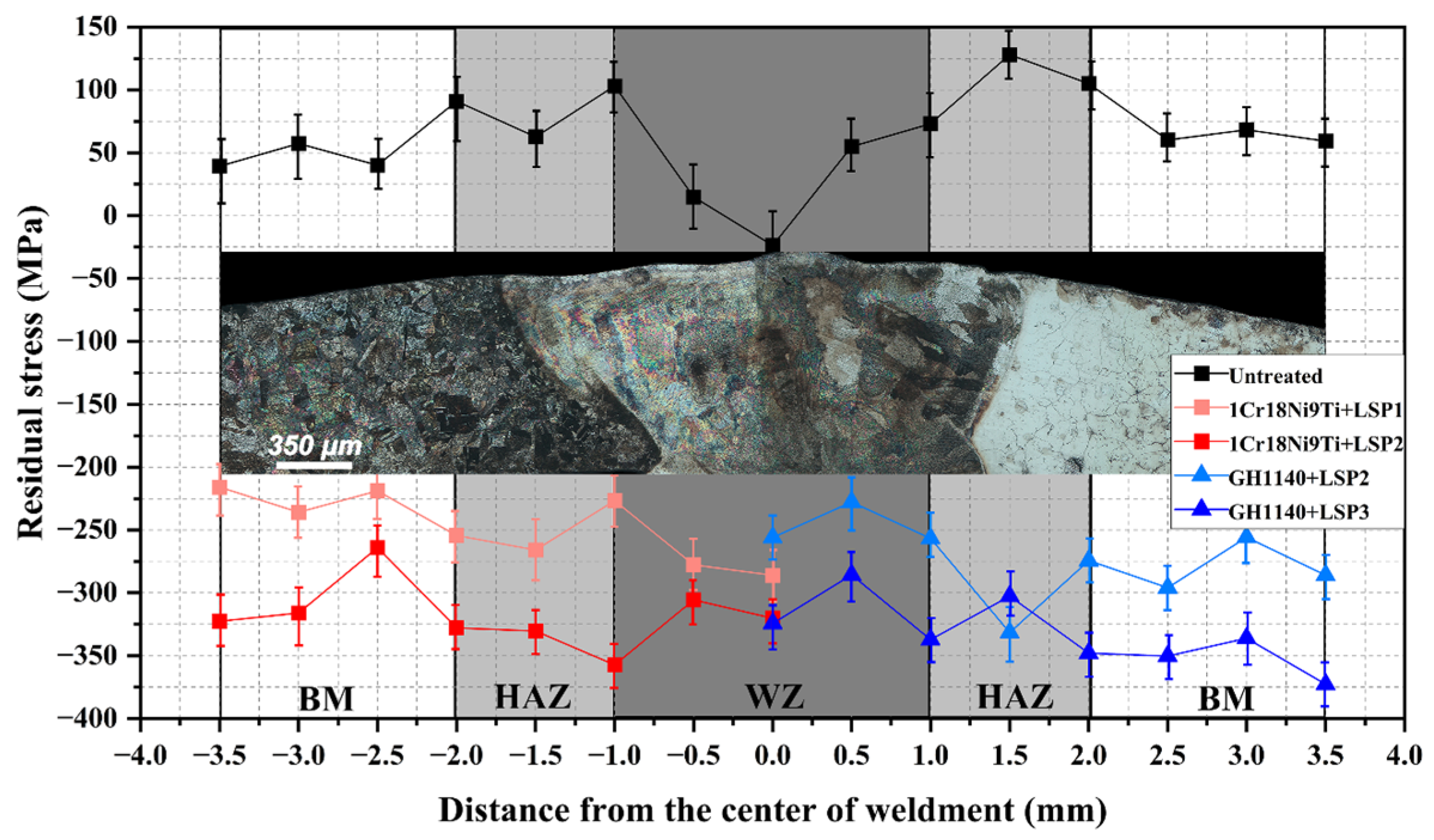
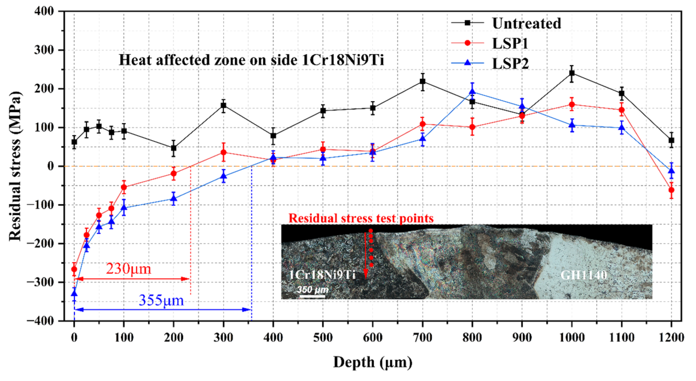
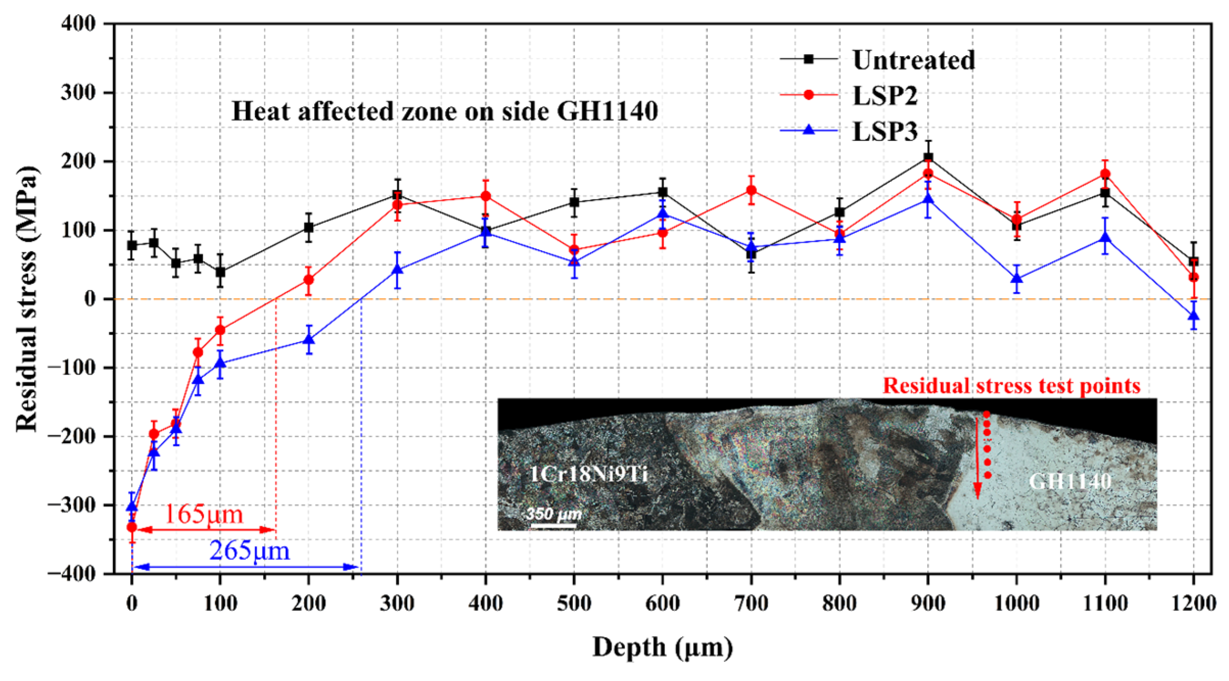
3.1. Residual Stress Distribution

Figure 3 shows the distribution of residual stress on the weld surface of the combustion liner after LSP. It is obvious that the residual stress at the center of the combustion liner weld is compressive stress, while the residual stress at the direct boundary between the weld zone and the HAZ is tensile stress. In the HAZ, the residual tensile stress reached the maximum value, the average value of the residual tensile stress in the HAZ of the 1Cr18Ni9Ti where one side is ~85 MPa and the average value of GH1140 side is 102 MPa. With increasing distance from the weld center, the residual tensile stress decreases gradually. For this phenomenon, it is inferred that the high temperature during welding may contribute to the phase transformation of the metal structure and the volume expansion caused by the phase transformation can effectively counteract the cooling shrinkage deformation and introduce compressive stress, resulting in a final residual stress distribution [27,28,29,30]. According to the distribution of residual stress, the residual tensile stress mainly exists in and around the HAZ, which has a negative effect on the fatigue properties of the combustion liner weld. This is due to the thermal expansion and contraction inhomogeneity of the HAZ during heating and cooling cycles [31,32]. After LSP, the original residual tensile stress is transformed into high-amplitude residual compressive stress. Simultaneously, the residual compressive stress is distributed uniformly on the weld surface of the whole combustion liner and the crack generally originates from the stress concentration point. The uniform distribution of high-amplitude residual compressive stress is beneficial to restraining crack initiation and retarding crack propagation.
Figure 4 and Figure 5 show the depth residual stress distribution in the HAZ on the 1Cr18Ni9Ti and GH1140 sides of the combustion liner weld. In the 1Cr18Ni9Ti side HAZ of the combustion liner weld, the residual tensile stress is observed from the weld surface to the bottom. After LSP, a deep layer of residual compressive stress was introduced into the specimen. The maximum residual compressive stress is located on the surface and the residual compressive stress decreases along the depth direction. This is due to laser-induced shock wave pressure attenuation during propagation [33,34,35]. As shown in Figure 4, when the laser energy is 2 J, the influence layer depth of residual compressive stress in the 1Cr18Ni9Ti side HAZ reaches 230 μm, while when the laser energy is 3 J, the influence layer depth of residual compressive stress reaches 355 μm. The distribution of depth residual stress in the GH1140 side is similar to that in the 1Cr18Ni9Ti side. As shown in Figure 5, when the laser energy is 3 J, the influence layer depth of residual compressive stress in GH1140 side reaches 165 μm, while when the laser energy is 5 J, the influence layer depth of residual compressive stress reaches 265 μm.
It can be concluded that the LSP can change the initial residual tensile stress into high-amplitude residual compressive stress in the HAZ of the combustion liner weld and the affected layer is very deep. In addition, it is found that a deeper residual compressive stress layer can be introduced into the 1Cr18Ni9Ti side HAZ at the 3 J laser energy and a deeper residual compressive stress layer can be introduced into the GH1140 side of HAZ at the 5 J laser energy.

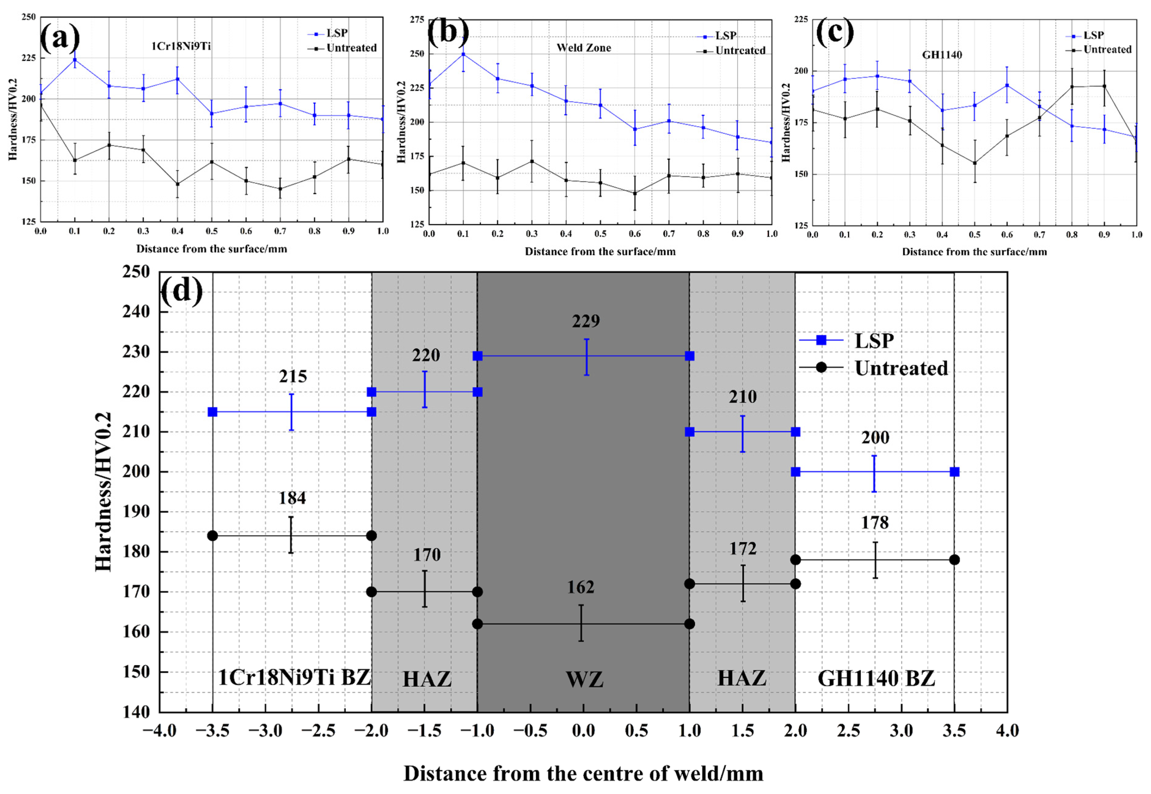
3.2. Microhardness Analysis

Figure 6 shows the average microhardness distribution between different areas of the combustion liner weld. The results show that the hardness of the whole combustion liner weld has some changes. It can be seen that the average hardness of the HAZ of 1Cr18Ni9Ti and GH1140 is almost the same, 170 HV and 172 HV, respectively, and the hardness of the substrate region of 1Cr18Ni9Ti is slightly higher than that of GH1140. The hardness of the weld zone is lower than that of the HAZ and substrate zone. The average hardness of the weld surface of the combustion liner increases with the distance from the weld center. Similar results were obtained in studies by Hatamleh et al. [36] and Sano et al. [37], in which the softening observed throughout the weld zone was likely due to coarsening and dissolution of the enhanced precipitates caused by the welding thermal cycle. Hardness increases with distance from the weld center due to more efficient precipitation hardening, eventually reaching the base metal hardness proposed by Hatamleh et al. [38,39].
After LSP, the surface hardness of every region of the combustion liner weld increased, especially in the weld zone, where the surface hardness increased by 41.4% from 162 HV to 229 HV. This shows that the LSP technology has a significant effect on improving the surface hardness of the weld of the combustion liner. The increase in hardness in the weld zone, HAZ and base material after LSP may be related to the introduction of a higher dislocation density, deformation twins and grain refinement [31].

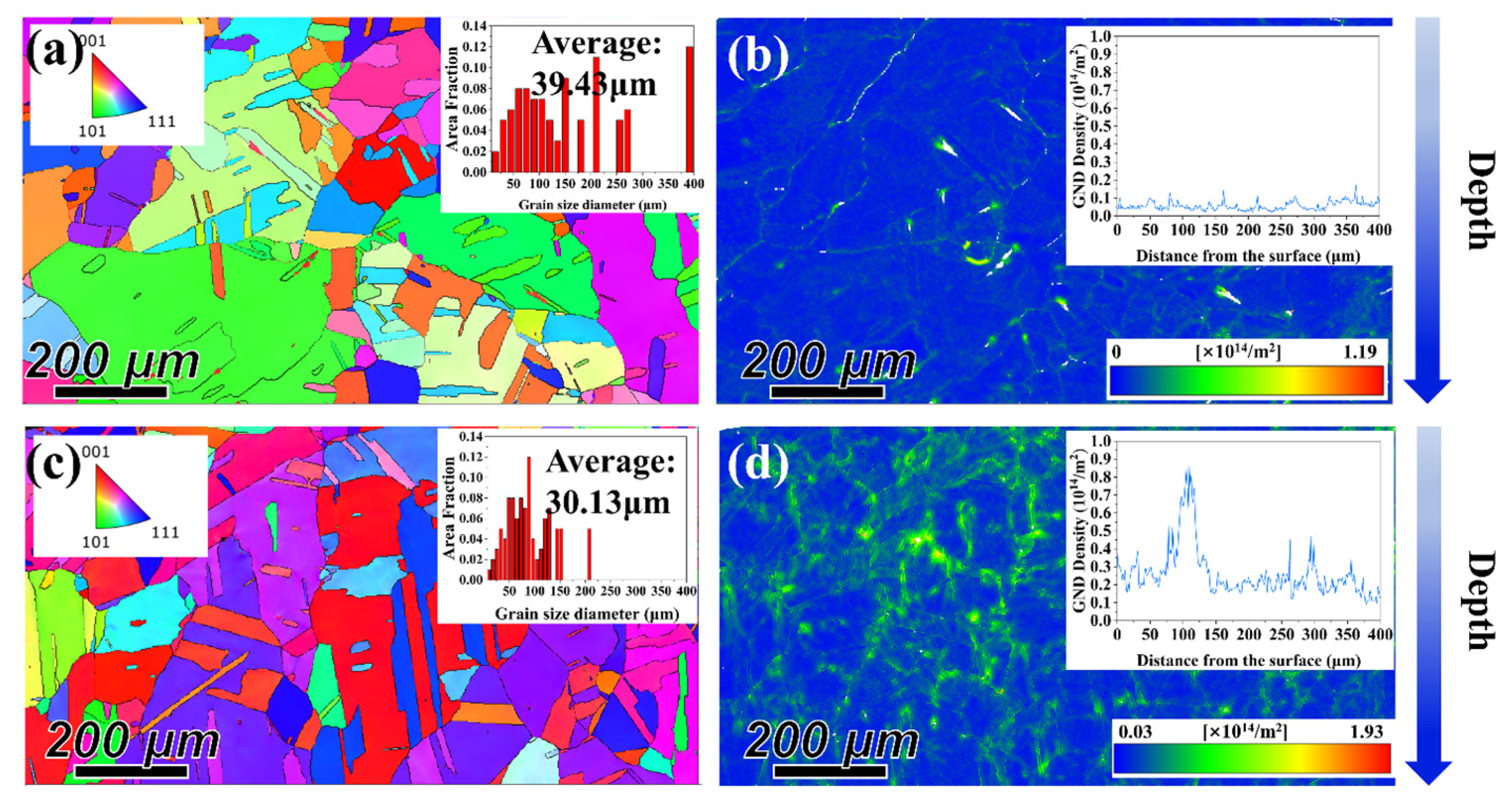
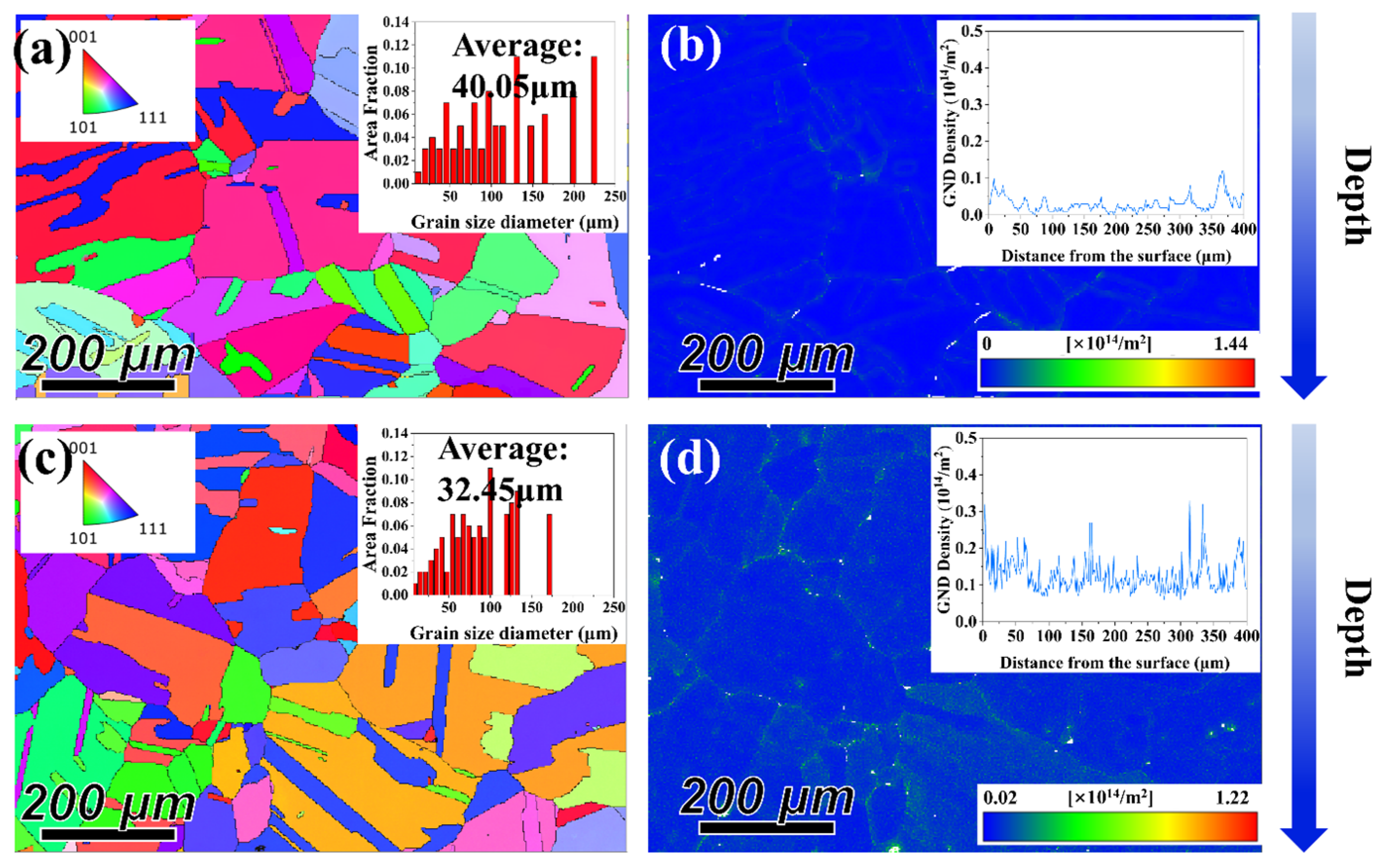
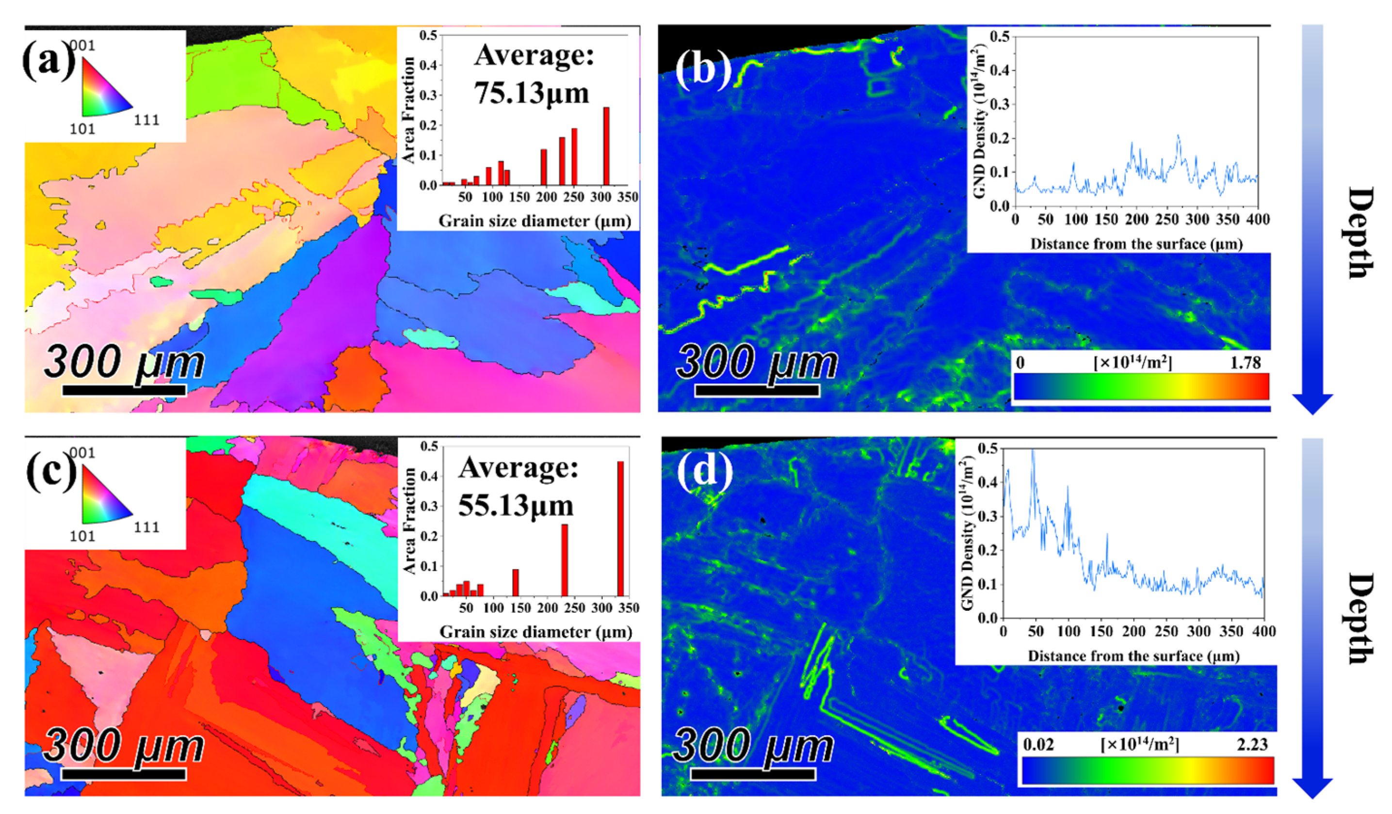
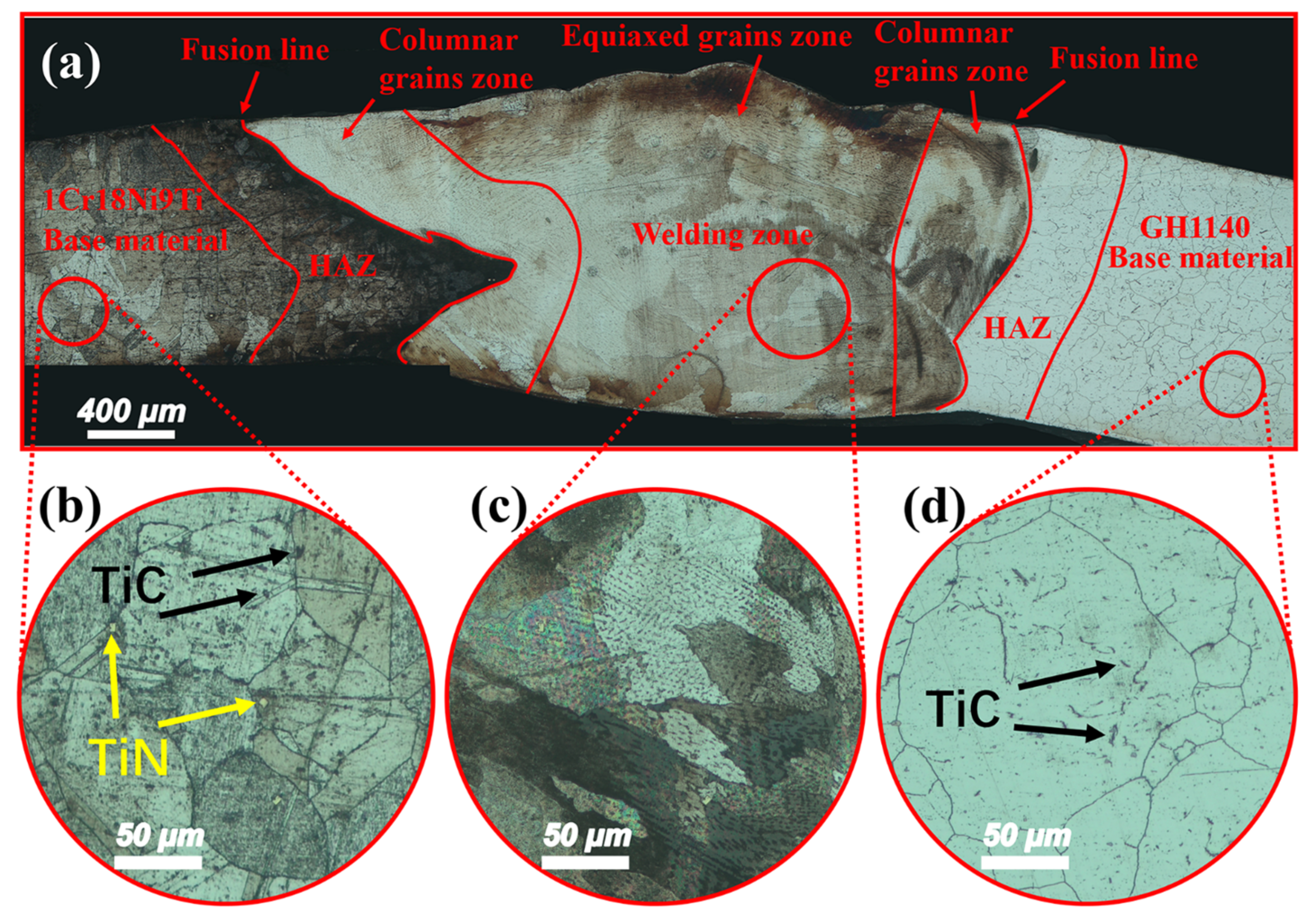
3.3. Microstructural Evolution

The initial microstructural characteristics of the weld zone in the combustion liner are shown in Figure 7a. Figure 7b–d show the magnified microstructural characteristics of the 1Cr18Ni9Ti, weld and GH1140 zones of the combustion liner weld, respectively. In Figure 7b, the matrix region of 1Cr18Ni9Ti is mainly composed of equi-axed polygonal austenite coarse grains with a small number of twins in the grains, and we can see that there is a clear block of golden yellow TiN and black TiC present. In the welding zone, mainly thick and long unevenly distributed grains were found, as shown in Figure 7c. In Figure 7d, the matrix region of GH1140 is mainly composed of equi-axed coarse ferrite grains. The distribution of grains is uneven.
The microstructures characteristics in HAZ on side 1Gr18Ni9Ti of the combustion liner weld and on side GH1140 of the combustion liner weld before and after LSP are shown in Figure 8 and Figure 9. As shown in Figure 8a, the grains in HAZ on side 1Gr18Ni9Ti are equiaxed, with a small number of annealed twins within the austenite grains and an average grain size of 39.43 μm. As shown in Figure 8c, the average grain size of HAZ on side 1Gr18Ni9Ti decreases by 23.57% and the average grain size of HAZ on side 1Gr18Ni9Ti decreases by 30.13 μm. As shown in Figure 9a, the grains in HAZ on side GH1140 are equiaxed with an average grain size of 40.05 μm. As shown in Figure 9c, many twinning structures appear in the original austenite grains in HAZ on side GH1140 after LSP and the average grain size of HAZ on side GH1140 is 32.45 μm; the average grain size of HAZ on side GH1140 decreases by 18.97%.
From Figure 8b,d and Figure 9b,d, it can be seen that the dislocation density of the specimen is distributed along the depth gradient after LSP and the dislocation depth generated in HAZ on side 1Gr18Ni9Ti is ~200 μm. This is consistent with the residual compressive stress introduced in the depth direction by LSP. The dislocation density distribution in HAZ on side GH1140 is also improved to some extent. It can be inferred that the dislocation structure with a certain density is introduced into the subsurface of the material by LSP, which shows that the plastic strain induced by LSP is also distributed with the depth gradient.
Figure 10 shows the microstructure of the weld zone of the combustion liner before and after LSP. As can be seen from Figure 10a, the microstructure of the original weld zone of the combustion liner is a coarse banded structure with an average grain size of 75.13 μm; compared with the base material (BM), the grain size more than doubles, which is related to uneven heat transfer and grain recrystallization growth during welding. As can be seen from Figure 10c, the grain size of the weld microstructure after LSP tends to be refined, with an average grain size of 55.13 μm, which is 26.6% lower than that of the original weld zone. It can also be seen from Figure 10b,d that LSP can introduce dislocation structures and plastic deformation in the depth direction.

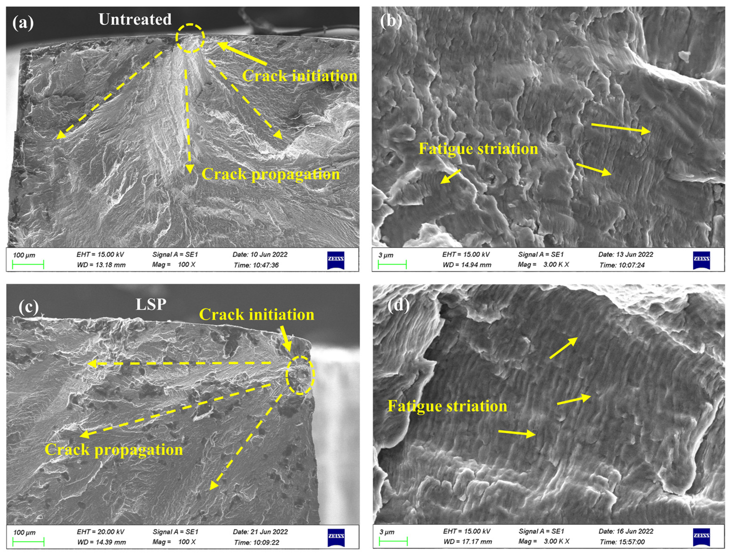
3.4. High-Cycle Fatigue Performance

Based on the residual stress distribution in the surface and depth directions for different parameters measured in Section 3.1, a set of laser shock peening parameters were determined to be applied to the 1Gr18Ni9Ti/GH1140 weld high-cycle tensile–tensile fatigue test specimen with laser parameters set as follows: laser parameter LSP2 for the 1Gr18Ni9Ti side of the weld and LSP3 for the GH1140 side. The sustainability and reliability of a component mainly depend on the fatigue limit of the material. The high-cycle tension–tension fatigue tests of the welded specimens were carried out by a step-loading method. As shown in Figure 11, the average fatigue limit of the 1Gr18Ni9Ti and GH1140 welded specimens, measured five times, was calculated to be 289 MPa, and for the specimens strengthened by LSP, the fatigue limit of the specimens was calculated to be 478 MPa and the fatigue limit was also increased by 65.39%. This shows that LSP can improve the fatigue performance of materials. The reason of this phenomenon is that the existence of high-amplitude residual compressive stress on the surface changes the position of the maximum alternating stress and effectively delays the initiation of fatigue crack. During the fatigue test, the local working tensile stress is counteracted by the surface compressive stress induced by the fact that the deformation of the specimen surface is limited, so that the fatigue crack is not easy to form.
The fracture morphology of LSP and untreated specimens is shown in Figure 12. The results show that the fatigue cracks of the untreated specimens start from the surface, and the source of cracks in LSP specimens also originates from the surface, as shown in Figure 12a,c. Figure 12b,d show the morphology of the crack propagation region in the zone. The results show that the fatigue band density of the materials strengthened by LSP is higher than that of the materials without laser shock peening, which indicates that laser shock peening can effectively reduce the fatigue crack growth rate. The existence of residual compressive stress reduces the stress intensity factor range and stress ratio R of fatigue crack growth, thus reducing the rate of fatigue crack growth. The closing effect of residual compressive stress on the micro-cracks also reduces the fatigue crack growth rate.
It is well known that the residual tensile stress produced during welding can be combined with the complex variable stress during service, which has a negative effect on the fatigue performance of materials. The residual compressive stress of high amplitude and deep influence layer can offset part of the external stress and make the crack initiation transfer to the depth direction. In other words, the residual compressive stress induced by LSP can shield the applied stress and prolong the fatigue life of crack initiation.

4. Conclusions

In this study, the effect of LSP on the high-cycle tension–tension fatigue performance of the 1Cr18Ni9Ti/GH1140 combustion liner weldment was studied. The following conclusions can be drawn.
(1)
The welding residual stress changes from the original residual tensile stress to the high-amplitude residual compressive stress. The average value of residual compressive stress is about −300 MPa and the depth of the influence layer of residual compressive stress in HAZ of 1Cr18Ni9Ti side reaches 355 μm. The influence layer depth of residual compressive stress in HAZ of GH1140 reaches 265 μm.
(2)
The grain refinement, gradient plastic deformation in the depth direction and dislocation structure of the surface material induced by laser shock peening can increase the resistance of fatigue crack initiation and propagation, thus improving the fatigue performance.
(3)
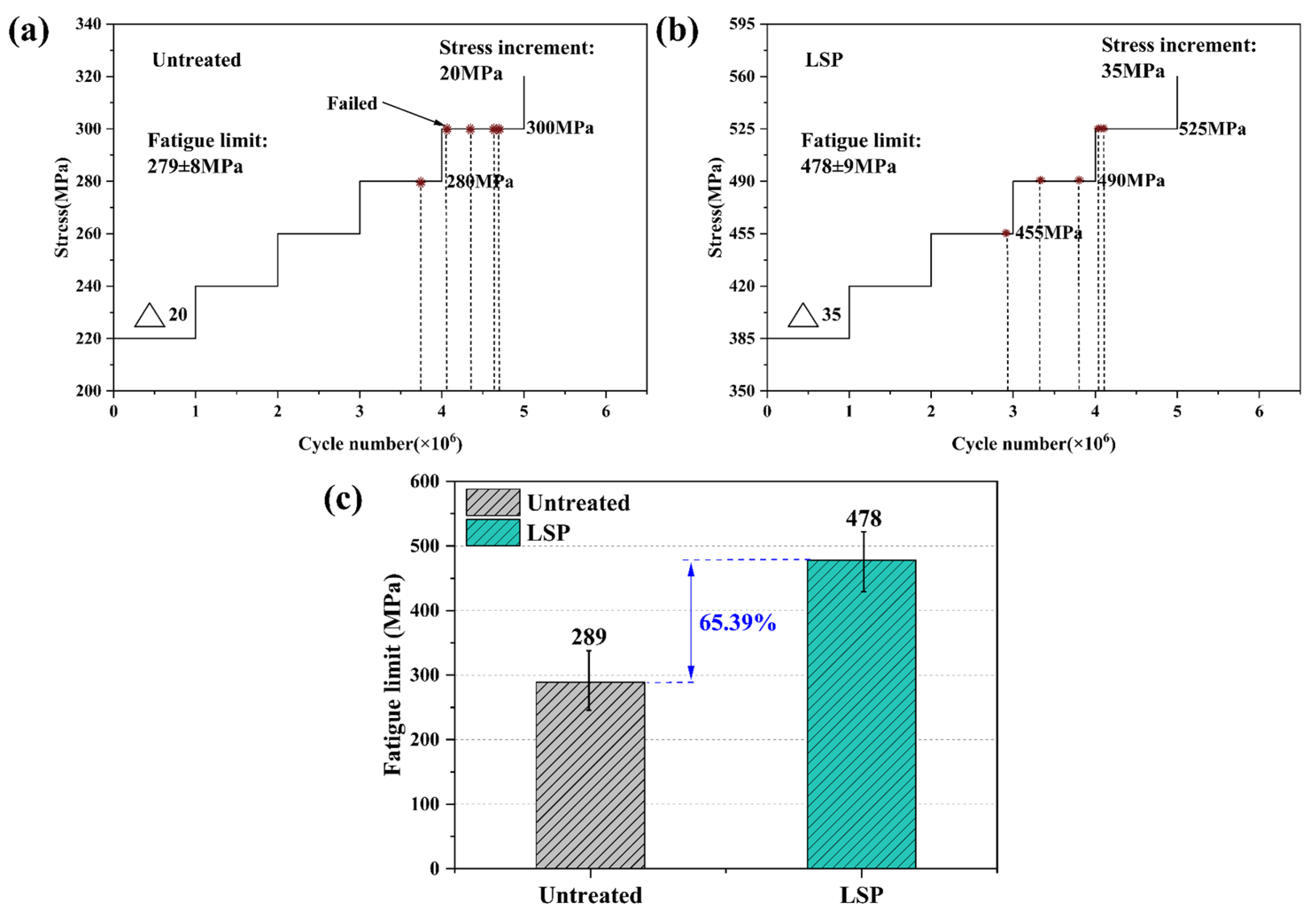
The high-cycle tensile–tensile fatigue limit of the 1CR18NI9TI/GH1140 welded joint was increased from 289 to 478 MPa. It is considered that this is the result of the interaction of high-amplitude residual compressive stress, grain refinement and gradient plasticity.

Author Contributions

Conceptualization, L.Z. and T.Z.; methodology, L.Z.; validation, T.Z. and Y.Y.; formal analysis, L.Z. and T.Z.; investigation, L.Z. and T.Z.; resources, L.Z. and P.L. and X.P.; data curation, T.Z.; writing—original draft preparation, L.Z and T.Z.; writing—review and editing, P.L. and X.P.; visualization, T.Z. and Y.Y.; supervision, L.Z.; project administration, L.Z. All authors have read and agreed to the published version of the manuscript.

Funding

This research was funded by “National Major Science and Technology Project of China, grant number J2019-I-0016-0015 and J2019-IV-0014-0082” and “National Natural Science Foundation of China, grant number 51875574”.

Institutional Review Board Statement

Not applicable.

Informed Consent Statement

Not applicable.

Data Availability Statement

The data used to support the findings of this study are available from the corresponding author upon request.

Acknowledgments

The authors thank the anonymous reviewers for their critical and constructive review of the manuscript.

Conflicts of Interest

The authors declare no conflict of interest.

References

  1. Ramkumar, K.D.; Arivazhagan, N.; Narayanan, S. Effect of filler materials on the performance of gas tungsten arc welded AISI 304 and Monel 400. Mater. Des. 2012, 40, 70–79. [Google Scholar] [CrossRef]
  2. Mortezaie, A.; Shamanian, M. An assessment of microstructure, mechanical properties and corrosion resistance of dissimilar welds between Inconel 718 and 310S austenitic stainless steel. Int. J. Press. Vessel. Pip. 2014, 116, 37–46. [Google Scholar] [CrossRef]
  3. Naffakh, H.; Shamanian, M.; Ashrafizadeh, F. Dissimilar welding of AISI 310 austenitic stainless steel to nickel-based alloy Inconel 657. J. Mater. Process. Technol. 2009, 209, 3628–3639. [Google Scholar] [CrossRef]
  4. Ramkumar, K.D.; Patel, S.D.; Praveen, S.S.; Choudhury, D.J.; Prabaharan, P.; Arivazhagan, N.; Xavior, M.A. Influence of filler metals and welding techniques on the structure-property relationships of Inconel 718 and AISI 316L dissimilar weldments. Mater. Des. 2014, 62, 175–188. [Google Scholar] [CrossRef]
  5. Chen, F.; Lv, Y.; Zhuang, X.; Zhong, G.; He, Y.; Yin, C. Effects of laser shock strengthening on performance of dissimilar metal welded joint. Hot Work. Technol. 2016, 45, 192–194. [Google Scholar]
  6. Ramkumar, K.D.; Sridhar, R.; Periwal, S.; Oza, S.; Saxena, V.; Hidad, P.; Arivazhagan, N. Investigations on the structure—Property relationships of electron beam welded Inconel 625 and UNS 32205. Mater. Des. 2015, 68, 158–166. [Google Scholar] [CrossRef]
  7. Neves, M.D.M.d.; Lotto, A.; Berretta, J.R.; de Rossi, W.; Junior, N.D.V. Microstructure development in Nd:YAG laser welding of AISI 304 and Inconel 600. Soldag. Insp. 2009, 14, 104–113. [Google Scholar] [CrossRef]
  8. Hosseini, H.S.; Shamanian, M.; Kermanpur, A. Characterization of microstructures and mechanical properties of Inconel 617/310 stainless steel dissimilar welds. Mater. Charact. 2011, 62, 425–431. [Google Scholar] [CrossRef]
  9. Jeng, S.L.; Lee, H.T.; Weirich, T.E.; Rebach, W.P. Microstructual study of the dissimilar joints of alloy 690 and SUS 304L stainless steel. Mater. Trans. 2007, 48, 481–489. [Google Scholar] [CrossRef]
  10. Yeh, T.-K.; Huang, G.-R.; Wang, M.-Y.; Tsai, C.-H. Stress corrosion cracking in dissimilar metal welds with 304L stainless steel and Alloy 82 in high temperature water. Prog. Nucl. Energy 2013, 63, 7–11. [Google Scholar] [CrossRef]
  11. Hassan, K.S.; Hanash, K.E.; Razooqi, A.I. Influence of shot peening on bending forces for MIG dissimilar welding joint aluminum alloys. In Proceedings of the 2nd International Conference on Sustainable Engineering Techniques (ICSET), Baghdad, Iraq, 6–7 March 2019. [Google Scholar]
  12. Logesh, M.; Selvabharathi, R.; Thangeeswari, T.; Palani, S. Influence of severe double shot peening on microstructure properties of Ti 6Al-4V and Titanium Grade 2 dissimilar joints using laser beam welding. Opt. Laser Technol. 2020, 123, 105883. [Google Scholar] [CrossRef]
  13. Ramkumar, K.D.; Kumar, P.S.G.; Krishna, V.R.; Chandrasekhar, A.; Dev, S.; Abraham, W.S.; Prabhakaran, S.; Kalainathan, S.; Sridhar, R. Influence of laser peening on the tensile strength and impact toughness of dissimilar welds of Inconel 625 and UNS 532205. Mater. Sci. Eng. A 2016, 676, 88–99. [Google Scholar] [CrossRef]
  14. Ghorbani, S.; Ghasemi, R.; Ebrahimi-Kahrizsangi, R.; Hojjati-Najafabadi, A. Effect of post weld heat treatment (PWHT) on the microstructure, mechanical properties, and corrosion resistance of dissimilar stainless steels. Mater. Sci. Eng. A 2017, 688, 470–479. [Google Scholar] [CrossRef]
  15. Leo, P.; D’Ostuni, S.; Nobile, R.; Mele, C.; Tarantino, A.; Casalino, G. Analysis of the process parameters, post-weld heat treatment and peening effects on microstructure and mechanical performance of Ti-Al dissimilar laser weldings. Metals 2021, 11, 1257. [Google Scholar] [CrossRef]
  16. Benchouia, S.; Merakeb, N.; Adjel, S.; Ehlers, S.; Baccouche, M.; Kaddour, A. Fatigue life enhancement of TIG-welded 304L stainless steels by shot peening. Int. J. Adv. Manuf. Technol. 2019, 100, 2885–2893. [Google Scholar] [CrossRef]
  17. Fu, Z.; Ji, B.; Kong, X.; Chen, X. Effects of Hammer Peening on Fatigue Performance of Roof and U-Rib Welds in Orthotropic Steel Bridge Decks. J. Mater. Civ. Eng. 2018, 30, 04018306. [Google Scholar] [CrossRef]
  18. Fueki, R.; Takahashi, K. Improving the fatigue limit and rendering a defect harmless by laser peening for a high strength steel welded joint. Opt. Laser Technol. 2021, 134, 106605. [Google Scholar] [CrossRef]
  19. Fueki, R.; Takahashi, K.; Handa, M. Fatigue Limit Improvement and Rendering Defects Harmless by Needle Peening for High Tensile Steel Welded Joint. Metals 2019, 9, 143. [Google Scholar] [CrossRef]
  20. Hensel, J.; Eslami, H.; Nitschke-Pagel, T.; Dilger, K. Fatigue Strength Enhancement of Butt Welds by Means of Shot Peening and Clean Blasting. Metals 2019, 9, 744. [Google Scholar] [CrossRef]
  21. Kinoshita, K.; Banno, Y.; Ono, Y.; Yamada, S.; Handa, M. Fatigue Strength Improvement of Welded Joints of Existing Steel Bridges by Shot-Peening. Int. J. Steel Struct. 2019, 19, 495–503. [Google Scholar] [CrossRef]
  22. Lago, J.; Trsko, L.; Jambor, M.; Novy, F.; Bokuvka, O.; Mician, M.; Pastorek, F. Fatigue Life Improvement of the High Strength Steel Welded Joints by Ultrasonic Impact Peening. Metals 2019, 9, 619. [Google Scholar] [CrossRef] [Green Version]
  23. Sano, T.; Eimura, T.; Hirose, A.; Kawahito, Y.; Katayama, S.; Arakawa, K.; Masaki, K.; Shiro, A.; Shobu, T.; Sano, Y. Improving Fatigue Performance of Laser-Welded 2024-T3 Aluminum Alloy Using Dry Laser Peening. Metals 2019, 9, 1192. [Google Scholar] [CrossRef]
  24. Soyama, H. Laser Cavitation Peening and Its Application for Improving the Fatigue Strength of Welded Parts. Metals 2021, 11, 531. [Google Scholar] [CrossRef]
  25. Soyama, H.; Simoncini, M.; Cabibbo, M. Effect of Cavitation Peening on Fatigue Properties in Friction Stir Welded Aluminum Alloy AA5754. Metals 2021, 11, 59. [Google Scholar] [CrossRef]
  26. Chattopadhyay, A.; Muvvala, G.; Sarkar, S.; Racherla, V.; Nath, A.K. Effect of laser shock peening on microstructural, mechanical and corrosion properties of laser beam welded commercially pure titanium. Opt. Laser Technol. 2021, 133, 106527. [Google Scholar] [CrossRef]
  27. Feng, X.; Pan, X.; He, W.; Liu, P.; An, Z.; Zhou, L. Improving high cycle fatigue performance of gas tungsten arc welded Ti6Al4V titanium alloy by warm laser shock peening. Int. J. Fatigue 2021, 149, 106270. [Google Scholar] [CrossRef]
  28. Shi, X.; Feng, X.; Teng, J.; Zhang, K.; Zhou, L. Effect of laser shock peening on microstructure and fatigue properties of thin-wall welded Ti-6Al-4V alloy. Vacuum 2021, 184, 109986. [Google Scholar] [CrossRef]
  29. Jiang, W.; Chen, W.; Woo, W.; Tu, S.-T.; Zhang, X.-C.; Em, V. Effects of low-temperature transformation and transformation-induced plasticity on weld residual stresses: Numerical study and neutron diffraction measurement. Mater. Des. 2018, 147, 65–79. [Google Scholar] [CrossRef]
  30. Ahn, J.; He, E.; Chen, L.; Wimpory, R.C.; Dear, J.P.; Davies, C.M. Prediction and measurement of residual stresses and distortions in fibre laser welded Ti-6Al-4V considering phase transformation. Mater. Des. 2017, 115, 441–457. [Google Scholar] [CrossRef]
  31. Dhakal, B.; Swaroop, S. Review: Laser shock peening as post welding treatment technique. J. Manuf. Processes 2018, 32, 721–733. [Google Scholar] [CrossRef]
  32. Becker, N.; Gauthier, D.; Vidal, E.E. Fatigue properties of steel to aluminum transition joints produced by explosion welding. Int. J. Fatigue 2020, 139, 105736. [Google Scholar] [CrossRef]
  33. Sanchez, A.G.; You, C.; Leering, M.; Glaser, D.; Furfari, D.; Fitzpatrick, M.E.; Wharton, J.; Reed, P.A.S. Effects of laser shock peening on the mechanisms of fatigue short crack initiation and propagation of AA7075-T651. Int. J. Fatigue 2021, 143, 106025. [Google Scholar] [CrossRef]
  34. Praveen, T.R.; Nayaka, H.S.; Swaroop, S. Influence of equal channel angular pressing and laser shock peening on fatigue behaviour of AM80 alloy. Surf. Coat. Technol. 2019, 369, 221–227. [Google Scholar] [CrossRef]
  35. Nie, X.; He, W.; Zhou, L.; Li, Q.; Wang, X. Experiment investigation of laser shock peening on TC6 titanium alloy to improve high cycle fatigue performance. Mater. Sci. Eng. A 2014, 594, 161–167. [Google Scholar] [CrossRef]
  36. Hatamleh, O.; Lyons, J.; Forman, R. Laser and shot peening effects on fatigue crack growth in friction stir welded 7075-T7351 aluminum alloy joints. Int. J. Fatigue 2007, 29, 421–434. [Google Scholar] [CrossRef]
  37. Sano, Y.; Masaki, K.; Gushi, T.; Sano, T. Improvement in fatigue performance of friction stir welded A6061-T6 aluminum alloy by laser peening without coating. Mater. Des. 2012, 36, 809–814. [Google Scholar] [CrossRef]
  38. Hatamleh, O. Effects of peening on mechanical properties in friction stir welded 2195 aluminum alloy joints. Mater. Sci. Eng. A 2008, 492, 168–176. [Google Scholar] [CrossRef]
  39. Hatamleh, O. A comprehensive investigation on the effects of laser and shot peening on fatigue crack growth in friction stir welded AA 2195 joints. Int. J. Fatigue 2009, 31, 974–988. [Google Scholar] [CrossRef]
Figure 1. (a) TIG welding diagram of 1Cr18Ni9Ti/GH1140 dissimilar material flat plate; (b) dimensional diagram of the high-cycle tension–tension fatigue specimen wire cut from the 1Cr18Ni9Ti/GH1140 dissimilar-material welded flat pieces in Figure (a); (c) laser shock peening area and its shock path for the tension–tension fatigue specimen in Figure (b); (d) welded joint diagram of combustion liner components; (e) sheet weld specimen cut off from Figure (d) and laser shock peening area and its shock path diagram.
Metals 12 01495 g001
Figure 2. (a) High -cycle tension–tension fatigue test specimen with UN-LSP; (b) High-cycle tension–tension fatigue test specimen with LSP; (c) High-cycle tension–tension fatigue test diagram.
Metals 12 01495 g002
Figure 3. Residual stress distribution on weld surface of combustion liner.
Metals 12 01495 g003
Figure 4. Depth residual stress distribution in HAZ on side 1Cr18Ni9Ti of combustion liner weld.
Metals 12 01495 g004
Figure 5. Depth residual stress distribution in HAZ on side GH1140 of combustion liner weld.
Metals 12 01495 g005
Figure 6. (a) Microhardness distribution along the depth direction in the 1Cr18Ni9Ti region before and after laser shock peening; (b) microhardness distribution along the depth direction in the GH1140 region before and after laser shock peening; (c) microhardness distribution along the depth direction in the weld region before and after laser shock peening; (d) surface hardness distribution of combustion liner weld.
Metals 12 01495 g006
Figure 7. (a) Initial microstructural characteristics of the weld zone in the combustion liner. (b) Amplified organization of 1Gr18Ni9Ti base material; (c) amplified organization of weld region; (d) amplified organization of GH1140 base material.
Metals 12 01495 g007
Figure 8. Microstructural characteristics in HAZ on side 1Gr18Ni9Ti of combustion liner weld with LSP and UN-LSP: (a) IPF mapping with UN-LSP; (b) GND density mapping with UN-LSP; (c) IPF mapping with LSP; (d) GND density mapping with LSP.
Metals 12 01495 g008
Figure 9. Microstructural characteristics in HAZ on side GH1140 of combustion liner weld with LSP and UN-LSP: (a) IPF mapping with UN-LSP, (b) GND density mapping with UN-LSP, (c) IPF mapping with LSP, and (d) GND density mapping with LSP.
Metals 12 01495 g009
Figure 10. Microstructural characteristics of weld zone of combustion liner weld with LSP and UN-LSP: (a) IPF mapping with UN-LSP, (b) GND density mapping with UN-LSP, (c) IPF mapping with LSP, and (d) GND density mapping with LSP.
Metals 12 01495 g010
Figure 11. High-cycle vibration fatigue limit at 106 cycle numbers of as-welded specimens treated using LSP. (a) Untreated. (b) LSP. (c) High-cycle fatigue test results of weld specimens.
Metals 12 01495 g011
Figure 12. Fracture morphologies of specimens with and without LSP treatment: (a) crack initiation region of untreated specimens, (b) crack propagation region of untreated specimens, (c) crack initiation region of LSPed specimens, and (d) crack propagation region of LSPed specimens.
Metals 12 01495 g012
Table 1. Chemical compositions of 1Cr18Ni9Ti stainless steel and GH1140 Ni-based superalloy (wt.%).
MaterialsCSiMnPSNiCrTiWMoAlFe
1Cr18Ni9Ti0.110.961.97<0.035<0.0309.6618.540.78000Bal
GH11400.080.30.30040211.01.42.10.3Bal
A2020.080.81.50.020.0314201.002.00.3Bal
Table 2. Mechanical properties of 1Cr18Ni9Ti stainless steel and GH1140 Ni-based superalloy.
Properties1Cr18Ni9TiGH1140
Yield strength σ0.2 (MPa)205
Ultimate tensile strength σb (MPa)520635
Elongation rate δ (%)4040
Elastic modulus (GPa)206
Table 3. Parameters of LSP treatments.
SpecimenWavelength (nm)Lapping RateSpot Diameter (mm)Energy (J)Power Density (GW/cm2)Laser Impacts
LSP1106450%2.222.631
LSP2106450%2.233.941
LSP3106450%2.256.571
Publisher’s Note: MDPI stays neutral with regard to jurisdictional claims in published maps and institutional affiliations.

