Article

Impact of Processing on the Creep Properties of High Performance Ferritic (HiperFer) Steels

Institute of Energy and Climate Research (IEK), Microstructure and Properties of Materials (IEK-2), Forschungszentrum Jülich GmbH, 52425 Jülich, Germany
*
Author to whom correspondence should be addressed.
Current address: Voestalpine Böhler Welding UTP Maintenance GmbH, Elsäßer Str. 10, 79189 Bad Krozingen, Germany.
Metals 2022, 12(9), 1459; https://doi.org/10.3390/met12091459
Submission received: 19 July 2022 / Revised: 29 August 2022 / Accepted: 29 August 2022 / Published: 30 August 2022

Abstract

:
High performance ferritic (HiperFer) stainless steels constitute a new class of low-cost, heat resistant, hardenable materials which combine high creep and fatigue strength with increased steam oxidation and wet corrosion resistance. The fundamental relationships regarding the alloy composition, microstructure, and resulting mechanical properties are largely known and already published, while relevant commercialization issues, such as the effect of processing on the microstructure, have not yet been addressed. The current paper outlines the impact of the forming parameters on the resulting microstructure and the achievable creep properties. Thermomechanical treatment is demonstrated as an effective method for increasing the creep strength for a given chemical composition. This may constitute a key enabler for cost savings in component production, e.g., for the simple machining of “drop-in” turbine blades or bolts from forged bar stock material.

1. Introduction

In today’s power engineering, advanced ferritic-martensitic (AFM) 9–12 wt.% Cr structural steels are widely applied at application temperatures from 560 to 620 °C [1,2]. The 9 wt.% Cr steels are limited to temperatures lower than 620 °C because they lack steam oxidation resistance [2,3]. The 12 wt.% Cr steels, optimized for application beyond 620 °C, often suffer a drop in creep strength during long-term application [4], because of the formation of the so called Z-phase, a complex Cr(V, Nb)N, which consumes the strengthening MX (M: metal, X: C/N) particles [5,6]. The development of improved AFM steels has stagnated throughout recent decades because of this seemingly irresolvable conflict of aims, making novel approaches necessary.
The Japanese National Institute of Materials Science (NIMS) demonstrated superior matrix inherent long-term creep strength [7,8] of ferritic and pearlitic matrix-type steels. Based on this finding, NIMS patented a ferritic 15 wt.% Cr concept steel [9], which is mainly strengthened by a solid solution and a secondary phase (Fe2W: Laves, Fe36Cr12W10: χ, Fe7W6: µ, M23C6: carbide, (Cr(V,Nb)N): Z) particle precipitation. Over the last years several versions of this novel steel type have been published, demonstrating promising creep strength [10,11,12,13,14,15,16] and processing significance [17]. Lu et al. [18] even published a computational approach to optimize this type of precipitation strengthened ferritic steel.
“HiperFer” [19] steel seeks to provide a highly steam oxidation, wet corrosion, fatigue resistant, and cost-effective material solution for cyclically operated power equipment. It constitutes a fully ferritic, high chromium (17 wt.%), stainless alloy matrix, strengthened by a solid solution (by W, Nb, and Cr) and (Fe,Cr,Si)2(Nb,W) Laves phase precipitation [20,21]. The creep strength of these grades outperforms grade 92 steel, while its resistance to steam oxidation is superior, even to the 12 wt.% Cr AFM steels [21]. Operational flexibility currently plays a very important role, and it will strongly increase in importance in future thermal power conversion [22]. For this reason, increased thermomechanic fatigue resistance [19,23,24] was the main focus of HiperFer development. Creep strength nevertheless remained as an important issue, because it allows for thinner wall sections and lower investment costs. HiperFer is fully ferritic and for this reason (i.e. the absence of a γ-iron phase at high temperature), does not transform to martensite upon (rapid) cooling. This provides the advantage of intrinsic freedom from the premature creep rupture of weldments (known as TypeIV-cracking [25,26]), but on the other hand, necessitates that special care must be taken in the forming processes involved. For a given chemical composition, the current paper outlines the impact of four different sets of rolling parameters on material microstructure and the resulting creep properties.

2. Experimental

2.1. Base Metal Production and Processing

The trial steels presented in this study were produced by vacuum induction melting (VIM) at the Steel Institute (IEHK) of the Northrhine-Westfalian Technical University Aachen (RWTH), Germany, utilizing high purity materials. The chemical compositions of the steels were analyzed by inductively coupled plasma optical emission spectroscopy (ICP-OES, Thermo Scientific ICP_OES 6500, Waltham, MA, USA; C, N were analyzed by infrared absorption) and are shown in Table 1.
The materials were cast into blocks (dimensions: 140 mm × 140 mm × ~ 525 mm). These were forged to 80 mm × 56 mm at the cross-section and subsequently air-cooled. The resulting slabs were then cut into pieces of approx. 135 mm in length. Soaking, rolling, and subsequent cooling was carried out, as schematically represented in Figure 1. The applied parameters are summarized in Table 2. The rolling parameter variations applied (hereafter referred to as "_1", "_2", "_3", and "_4") in all cases resulted in 15 mm thick plate material.

2.2. Mechanical Testing

Creep specimens with a gauge diameter of 6.4 mm and a gauge length of 30 mm were machined from the rolled plate materials perpendicular to the rolling direction.
In-house, custom-built constant load, single specimen, lever-arm creep machines, equipped with continuous elongation measurement and electrical three-zone furnaces, controlled to an accuracy of +/− 2 °C, were applied in the creep experiments. Type R (Pt/RhPt) thermocouples, attached to the specimen gauge lengths, were used for temperature control. Heating to the designated testing temperature was performed at a rate of 5 K/min; the target temperature then was maintained for one hour to ensure equilibrium conditions before applying the load.

2.3. Microstructural Investigation

Samples for initial microstructure investigation were prepared from the plate materials by electrical discharge machining (EDM). The specimens were mounted in epoxy resin, ground, and polished to a sub-micron finish in a colloidal silica suspension for approx. 4 h. Electrolytical etching at 1.5 V in 5% H2SO4 was performed subsequently to enhance the particle/matrix contrast. Light optical (Leica MEF4, Leica Camera AG, Wetzlar, Germany) and scanning electron microscopes (Zeiss Merlin, Oberkochen, Germany) were applied for characterization.

3. Results

3.1. Impact of Processing on Initial Microstructure

HiperFer steel is fully ferritic, i.e., it lacks an austenite phase at high temperatures. For this reason, it does not undergo martensitic transformation (fcc => bct) upon cooling from process heat, which makes its mechanical properties dependent on either thermomechanical processing [27] (rolling, forging, bending, welding and cooling) and/or dedicated heat treatment consisting of recrystallization and precipitation annealing (not addressed in this paper). On the other hand, HiperFer for this reason is intrinsically free from fine grain formation within the heat-affected zones (HAZ) of welds and thus potentially insensitive to so-called Type IV cracking and associated premature creep failure, which is quite common in 9–12 Cr AFM steels [25,26].
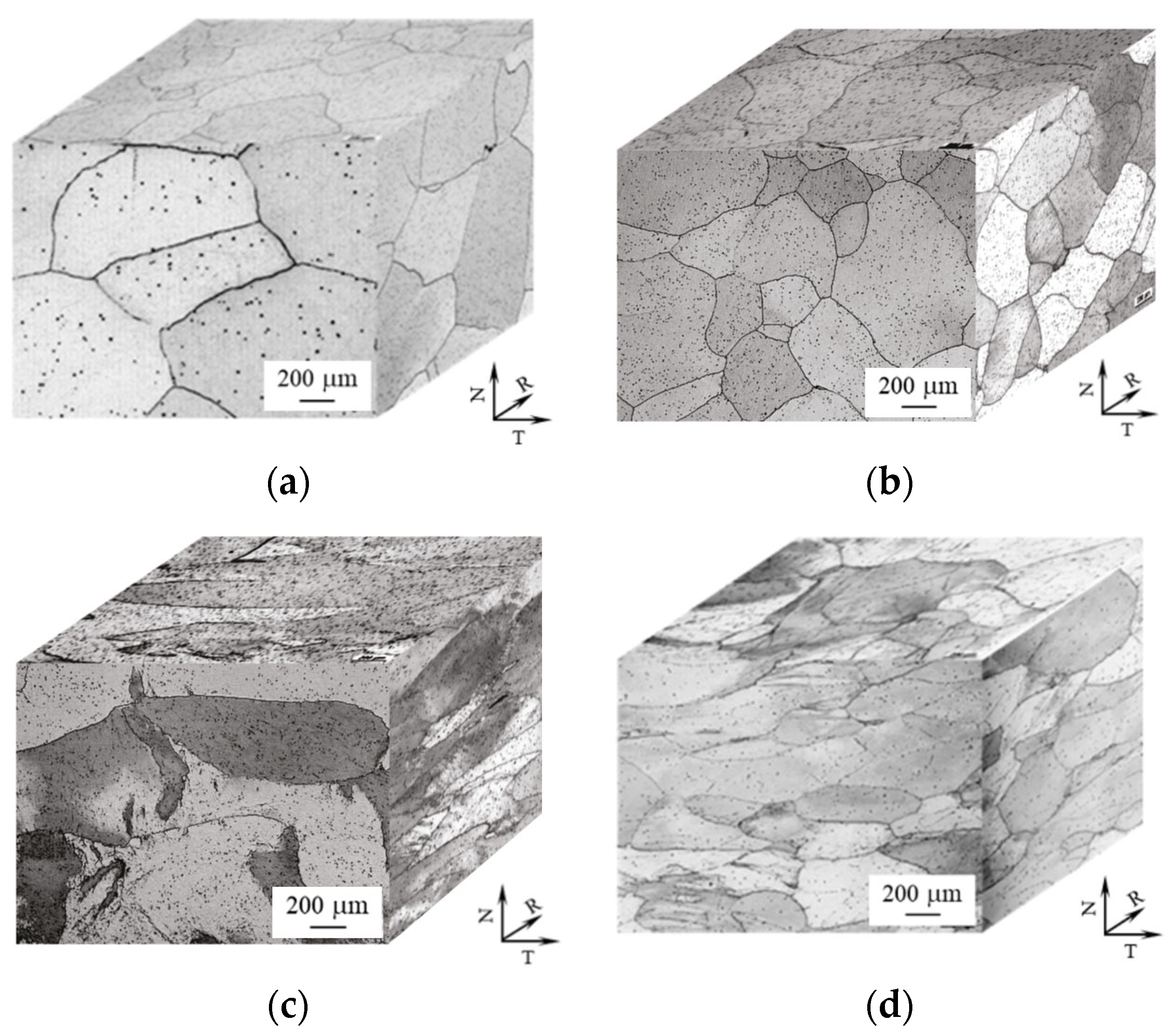
The rolling of HiperFer steel aims at a suitable combination of grain size (to provide sufficient creep ductility) and dislocation strengthening (provided by the last thickness reduction step, carried out at lower temperatures, and subsequent rapid cooling, cf. Figure 1). The processing of the trial steels consequently consisted of several thickness reduction and interpass annealing steps (cf. Figure 1 and Table 2). It is noteworthy that no interpass annealing was carried out previous to, and that the temperature was decreased for the last rolling pass. Rolling and interpass annealing in the temperature range from 1000–960 °C (i.e., below the dissolution temperature of Laves phase precipitates, Td) effectively prevented grain growth and allowed for adequate stress reduction. Final interpass annealing above Td at 1100 °C for 22 (parameter set “_1,” cf. Table 2) to 35 min (set “_2,” Table 2) led to almost globular grain morphology, without significant anisotropy (cf. Figure 2a reproduced from [19] and Figure 2b).
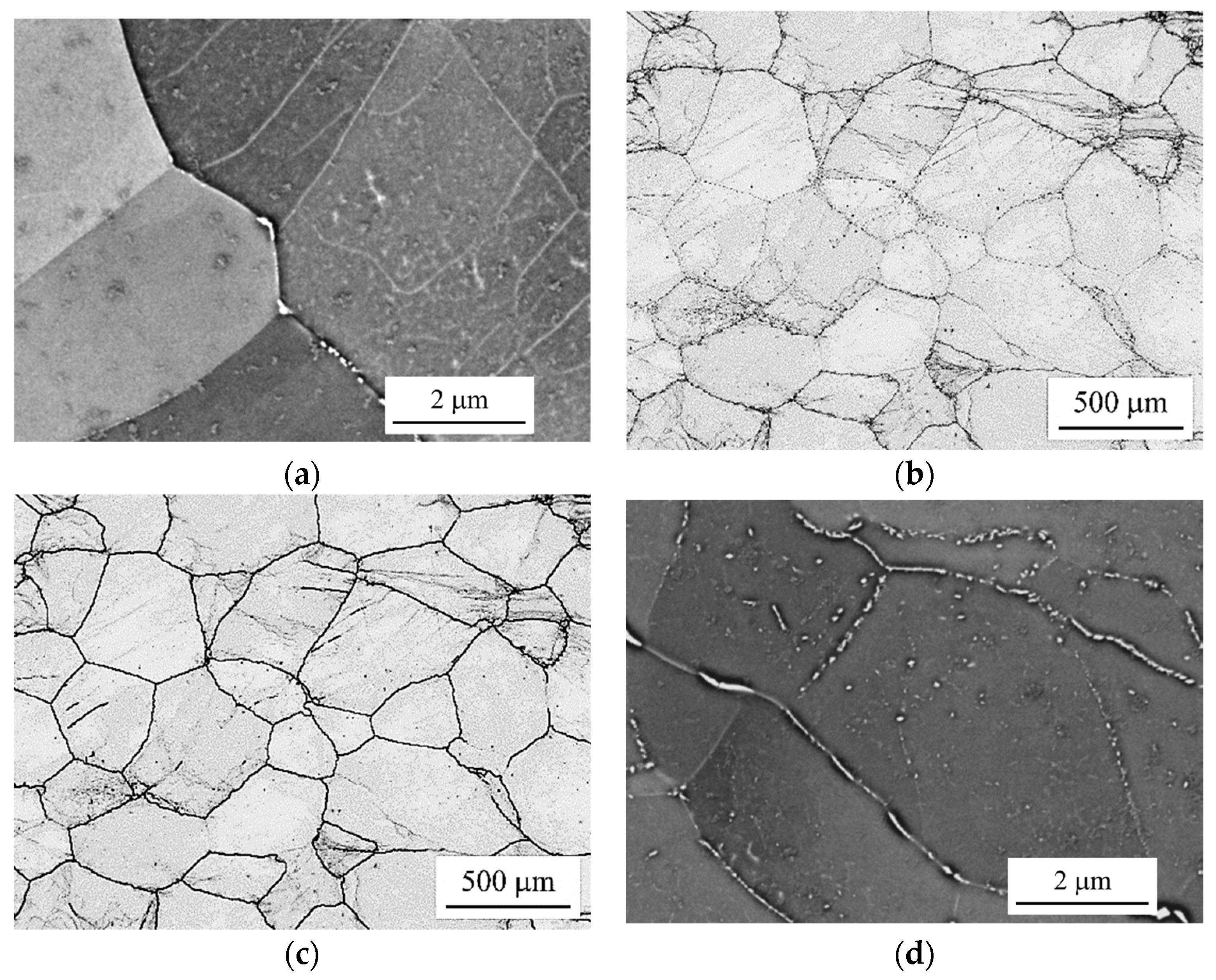
Slow cooling in air led to pronounced recovery and resulted in low dislocation density, which translated into comparatively low hardness, around 215 HV0.001 in case of deformation parameter sets _1 and _2. High angle grain boundaries were found decorated by small, primary Laves phase particles. Very few Laves phase precipitates populated the grain interiors (cf. Figure 3a, representing the deformation parameter sets “_1” and “_2”). This kind of microstructure yielded comparably low creep strength values, but superior ductility (cf. Section 3).
A decreased number of thickness reduction steps, decreased rolling and interpass annealing temperatures, and increased deformation in the final rolling step (cf. parameter set “_3” in Table 2) yielded coarser grains, elongated along the rolling and transversal directions (cf. Figure 2c). Rapid water quenching helped to preserve increased residual dislocation density (260 HV0.001), which yielded superior creep-rupture times, but deteriorated ductility (cf. Section 3).
Creep ductility was restored by a reduction in grain size (cf. Figure 2d) achieved by a lower final interpass annealing temperature and time (parameter set “_4”). Furthermore, intermediate dislocation density was achieved by reduced deformation in the final thickness reduction step and preserved by rapid water quenching (230 HV0.001). The initial precipitate microstructure achieved in this way was similar to parameter sets “_1” and “_2” (cf. Figure 3a), since increased precipitation kinetics (because of increased dislocation density) were counterbalanced by rapid water quenching. These optimized process parameters yielded a viable compromise between initial dislocation strengthening, suitable grain size, rapid precipitation kinetics (during primary creep), and resulting creep rupture strength and ductility (cf. Section 3).
Figure 3a depicts an additional scanning electron micrograph of an as-rolled microstructure, typical for processing according to parameter sets “_1”, “_2,” and “_4”: The high-angle grain boundaries were sparsely decorated by Laves phase particles, and a well-defined sub-grain structure can be observed from Figure 3b,c. In case of processing by parameter set “_3” (Figure 3c), the few visible intragranular Laves phase particles originated from rolling at a comparably low temperature.

3.2. Impact of Processing on Creep Properties

3.2.1. Creep Curve Shape

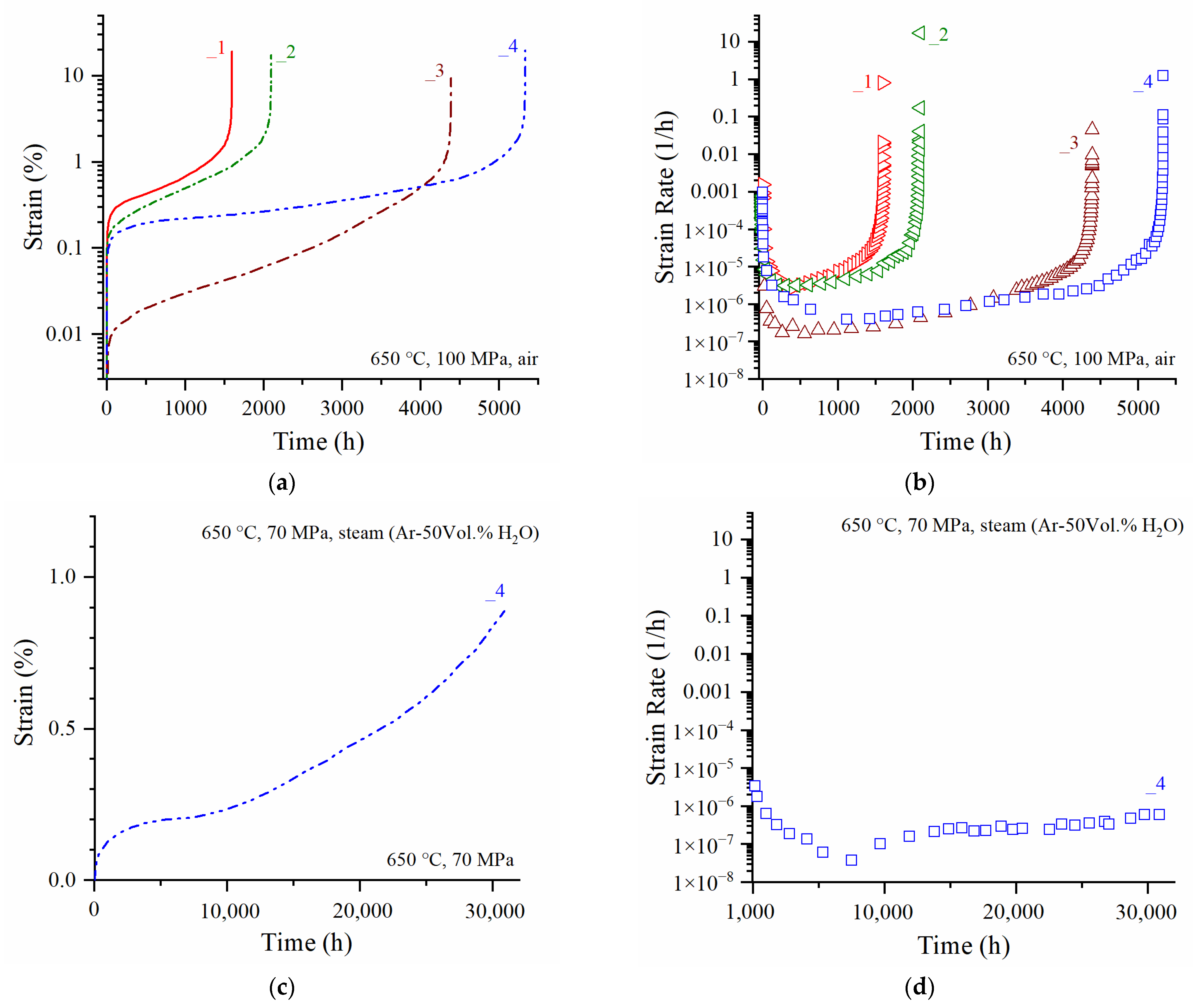
In the rolled condition, HiperFer steel exhibits an extensive primary stage and a very short—to nearly absent—secondary, steady-state stage of creep [28]. Dislocation density has a two-fold impact, especially in the primary stage: First, the increased density of dislocations in general provides a (short-term) strengthening effect. Second, it strongly affects the precipitation kinetics of the Laves phase and thus, the resulting particle number and size distribution, i.e., the precipitation strengthening effect. For these reasons, the applied processing parameters unfold a pronounced impact on the shape of the resulting creep curves. Figure 4 displays a comparison of exemplary creep (Figure 4a) and creep rate (Figure 4b) curves measured at the differently rolled plate materials at 650 °C and a stress level of 100 MPa.
With variations in rolling parameters, several differences in creep curve shape became obvious: The higher the initial dislocation density (“_1”: minimum, “_2”: low, “_3”: high), the lower the resulting primary creep strain, the longer the creep life (Figure 4a). While the materials of minimum and low initial dislocation density (“_1” and “_2”) yielded the expected primary stage creep strain values, the high dislocation density batch “_3” displayed aberrantly low primary creep strain and the lowest minimum creep rate (Figure 4b). Obviously, HiperFer does not present a classic secondary creep stage characterized by a constant creep rate over an extended period of time. Rather, the creep rate continuously decreases in the primary creep stage until the transition into the tertiary creep stage takes place. Deformation of HiperFer steel in the third stage is mainly governed by the accumulation of plastic strain within the particle-free zones (PFZ) at the grain boundaries [29,30]. For this reason, the increasing grain size from processing parameter sets “_1” and “_2” to set “_3” (compare Figure 2a–c) resulted in lower accumulated particle-free volume at the grain boundaries (i.e., lower volume to accommodate creep deformation) and consequently, a drop in creep rupture deformation. While the “_1” and “_2” batches reached ~ 20 %, creep rupture strain dropped to ~ 10% in the case of the aberrant batch “_3”. Compromising dislocation density and grain size, by applying the optimized processing parameter set “_4”, restored rupture ductility and resulted in the longest creep life of 5334 h, which ranges approximately 10% above the creep strength of ASTM Grade 92 steel [31]. Figure 4c depicts the actual status of the longest-running creep experiment performed using the optimized “_4” batch. At 70 MPa, it reached 0.89% of creep strain after 30883 h so far. The minimum creep rate reached at the end of the primary creep stage was evaluated to be 3.81 × 10⁻⁸ h−1 (Figure 4d). It must be mentioned that this experiment is performed under a simulated steam atmosphere (Ar-50 Vol.% H2O) to demonstrate the superior steam oxidation resistance of the HiperFer steel type, while all the other creep experiments in this study were performed in laboratory air.

3.2.2. Creep Property Evaluation

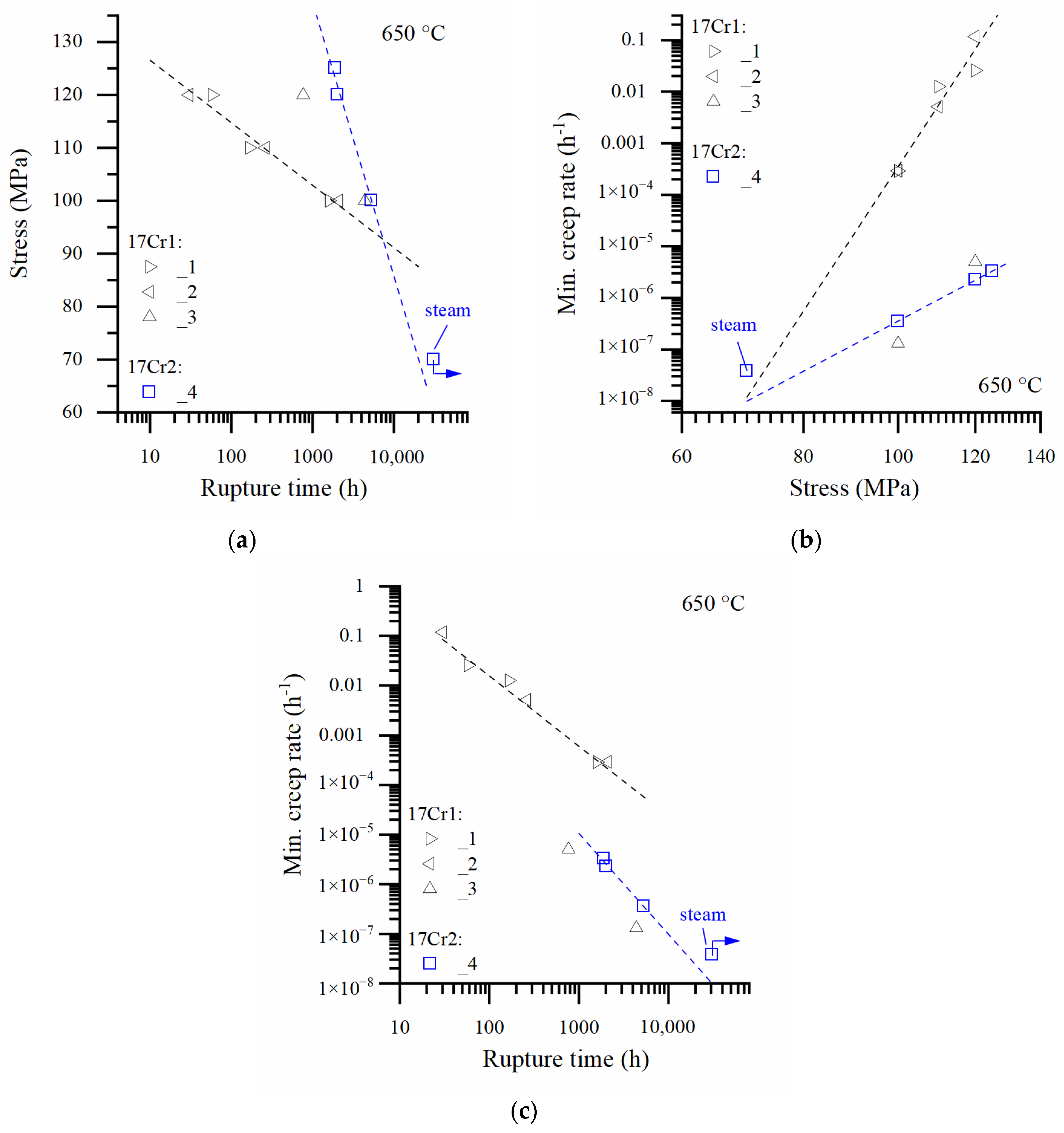
Figure 5 summarizes the 650 °C creep properties, evaluated for the as-rolled trial steels, in the stress range from 70 to 130 MPa. With the varying processing schedules from set “_1” to “_4,” creep life increased (Figure 5a), while the minimum creep rates dropped (Figure 3b). The synopsis and extrapolation of the results obtained in the stress range from 100 to 130 MPa suggests that the impact of processing fades out below a stress level of approximately 90 MPa (intersection of the batch trend lines in Figure 5a). Below this stress level (i.e., beyond this exposure time), processing should no longer have any significant impact (under the prerequisite of sufficient ductility provided by particle-free material volume to accommodate creep deformation, i.e., the combination of grain size and particle-free zone width), with creep mainly being controlled by particle stability. A total of 70 MPa was assessed from the proposed intersection of the batch (“_1” to “_4”: range from 1 to 3 × 10⁻⁸ h−1 at 70 MPa) data trend lines in the given plot of minimum creep rate vs. stress (Figure 5b) for validation experiments. Corresponding long-term experiments at the “_4” material variant are still in progress (cf. arrows in Figure 5a–c).
Optimized processing enabled a reduction of about two orders of magnitude in terms of minimum creep rate (Figure 5b,c). The 70 MPa validation experiment (carried out in a simulated steam environment) already exceeded the rupture time prediction (Figure 5a,c; being fully aware that both the predicted lower and upper values ignore the maximum allowable extrapolation factor of 3), based on the minimum creep rates of the higher stress (130–100 MPa) experiments (Figure 5b).
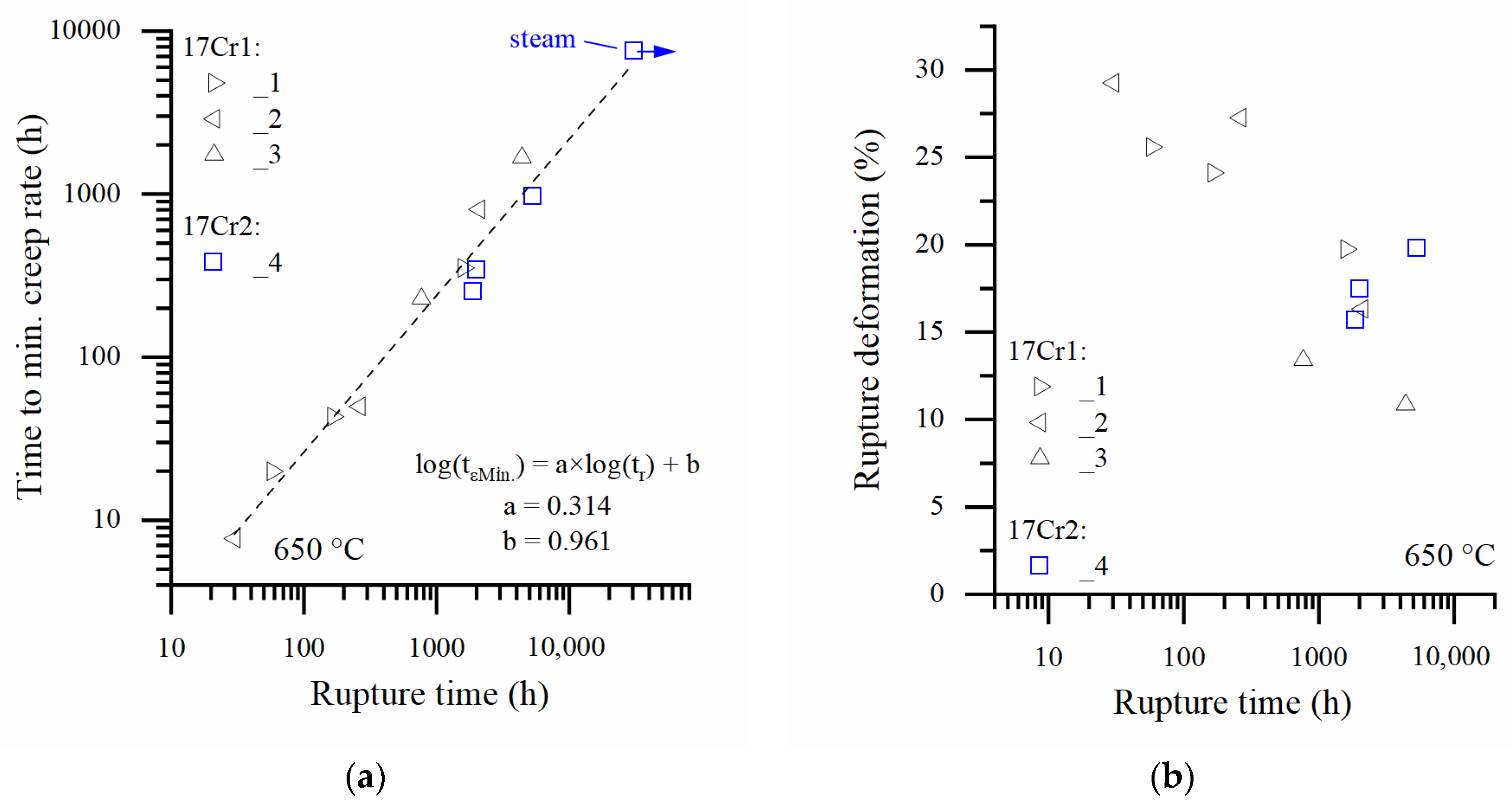
Ease of monitoring is a mandatory requirement for materials applied in power engineering. Related to creep, sufficient degrees of tertiary creep and rupture deformation are desired. All the trial steels obey the same time-to-minimum creep rate/time-to-rupture relationship (cf. Figure 6a, with the ongoing 70 MPa experiment of batch 17Cr2_4 excluded from the evaluation):
log(tεMin.) = a × log(tr) + b
Considering the values of the regression constants (a = 0.314 and b = 0.961), it can be concluded that appr. 67% of creep life lies within the short secondary, and predominantly the tertiary, stage of creep, making the material easy to monitor.
Despite its creep strength, HiperFer steel provides adequate creep rupture deformation (cf. Figure 6b), if properly processed. The only exception from this was the “_3” batch, where processing resulted in comparatively coarse, heavily deformed grains, which limited ductility in the low temperature tensile [27] and high temperature creep experiments (Figure 6b).

3.3. Precipitate Microstructure Evolution during High Temperature Application

If applied at temperatures equal to or higher than 600 °C, a multitude of Laves phase precipitates forms rapidly.
In the as-rolled state, particles preferentially nucleate at grain boundaries, sub-grain boundaries, and dislocations (Figure 7a) within a short time. Precipitate size, number, and spacing, as well as PFZ width, can be tuned by alloy composition [32], processing [30], and heat treatment [19]. The sub-grain structure from rolling disappeared and particle-free zones formed along the high-angle grain boundaries during long-term elevated temperature exposure (Figure 7b). Creep deformation of HiperFer-type steel is mainly determined by the coarsening of the strengthening precipitates [21,33,34]. Creep damage and failure, on the other hand, are mainly governed by the accumulation of plastic strain within the PFZs, located at the high-angle grain boundaries [19,29,35]. For this reason, engineering grain size and PFZ width is an important issue in controlling (creep) ductility [29].

4. Conclusions and Outlook

Under appropriate processing conditions, HiperFer steel provides promising creep and fatigue strength and steam oxidation properties superior to commercial AFM steel. For these reasons, it can be considered as a high potential candidate material for a broad range of applications, including future power technology equipment, such as conventional back-up power, heat storage [36,37], and concentrating solar power [38,39] plants or “Power-2-X” [40] conversion systems, due to its improved efficiency and high flexibility potentials.
Thermomechanical processing governs grain size, grain, and sub-grain structure, as well as the initial dislocation density of fully ferritic (i.e., no martensitic transformation) HiperFer type steel. This directly affects precipitation morphology, precipitation kinetics, particle-free zone width at high-angle grain boundaries, in turn determining creep deformation (i.e., creep curve shape), achievable rupture strength, and creep ductility.
Goal-oriented thermomechanical treatment (TMT) can thus be an option to tune specific mechanical properties without excessive heat treatment procedures. This can be a key enabler for new approaches to the cost-saving production of components, for example, simple machining of “drop-in” turbine blades or bolts from forged bar stock material.
Nevertheless, suitable quality heat treatment procedures consisting of recrystallization and precipitation annealing, for applications in which welding is involved (tubing, piping), are currently under study, and the results will be published soon.

Author Contributions

Conceptualization, B.K. and M.T.; methodology, B.K. and M.T.; validation, B.K. and M.T.; formal analysis, B.K. and M.T.; investigation, B.K. and M.T.; resources, B.K.; data curation, B.K. and M.T.; writing—original draft preparation, B.K.; writing—review and editing, M.T.; visualization, B.K.; supervision, B.K.; project administration, B.K.; funding acquisition, B.K. All authors have read and agreed to the published version of the manuscript.

Funding

This research was funded by the German Helmholtz Society Framework Programme “Energy Efficiency, Materials, and Resources”. Part of this research was funded by the German Ministry of Education and Research, under grant number 03EK3032.

Institutional Review Board Statement

Not applicable.

Informed Consent Statement

Not applicable.

Data Availability Statement

Not applicable.

Acknowledgments

The authors would like to acknowledge the support of Burkhardt Werner and Harald Reiners regarding mechanical testing, Volker Gutzeit and Jörg Bartsch for metallographic sample preparation, and Egbert Wessel and Daniel Grüner for microstructural investigation.

Conflicts of Interest

The authors declare no conflict of interest.

References

  1. Abe, F.; Kern, T.U.; Viswanathan, R. Alloy design philosophies of creep-resistant steel. In Creep Resistant Steels; Woodhead Publishing Limited: Cambridge, UK, 2008; pp. 541–570. [Google Scholar]
  2. Viswanathan, R.; Bakker, W. Materials for ultrasupercritical coal power plants—Boiler materials: Part 1. J. Mater. Eng. Perform. 2001, 10, 81–95. [Google Scholar] [CrossRef]
  3. Zurek, J.; De Bruycker, E.; Huysmans, S.; Quadakkers, W.J. Steam Oxidation of 9% to 12% Cr Steels: Critical Evaluation and Implications for Practical Application. Corrosion 2014, 70, 112–129. [Google Scholar] [CrossRef]
  4. Abe, F. Bainitic and martensitic creep-resistant steels. Curr. Opin. Solid State Mater. Sci. 2004, 8, 305–311. [Google Scholar] [CrossRef]
  5. Danielsen, H.K.; Hald, J. Behaviour of Z phase in 9–12% Cr steels. Energy Mater. 2006, 1, 49–57. [Google Scholar] [CrossRef]
  6. Danielsen, H.K.; Hald, J. Influence of Z-phase on Long-term Creep Stability of Martensitic 9 to 12% Cr Steels. VGB Power Tech. 2009, 5, 68–73. [Google Scholar]
  7. Kushima, H.; Kimura, K.; Yagi, K.; Tanaka, C.; Maruyama, K. Characterization of Creep Deformation Behaviour for Cr-Mo Steel. In Proceedings of the 7th JIM International Symposium on Aspects of High Temperature Deformation and Fracture in Crystalline Materials, Nagoya, Japan, 28–31 July 1993; Hosoi, Y., Yoshinaga, H., Oikawa, K., Maruyama, K., Eds.; Japan Institute of Metals: Sendai, Japan, 1993; pp. 609–616. [Google Scholar]
  8. Kimura, K.; Toda, Y.; Kushima, H.; Sawada, K. Creep strength of high chromium steel with ferrite matrix. Int. J. Press. Vessel. Pip. 2010, 87, 282–288. [Google Scholar] [CrossRef]
  9. Kimura, K. High-Chromium Containing Ferrite Based Heat Resistant Steel. European Patent No. EP1087028B1, 23 November 2005. [Google Scholar]
  10. Toda, Y.; Tohyama, H.; Kushima, H.; Kimura, K.; Abe, F. Influence of Chemical Composition and Heat Treatment Condition on Impact Toughness of 15Cr Ferritic Creep Resistant Steel. JSME Int. J. Ser. A Solid Mech. Mater. Eng. 2006, 48, 125–131. [Google Scholar] [CrossRef]
  11. Toda, Y.; Tohyama, H.; Kushima, H.; Kimura, K.; Abe, F. Improvement in Creep Strength of Precipitation Strengthened 15Cr Ferritic Steel by Controlling Carbon and Nitrogen Contents. JSME Int. J. Ser. A Solid Mech. Mater. Eng. 2005, 48, 35–40. [Google Scholar] [CrossRef]
  12. Kimura, K.; Seki, K.; Toda, Y.; Abe, F. Development of High Strength 15Cr Ferritic Creep Resistant Steel with Addition of Tungsten and Cobalt. ISIJ Int. 2001, 41, 121–125. [Google Scholar] [CrossRef]
  13. Toda, Y.; Seki, K.; Kimura, K.; Abe, F. Effects of W and Co on Long-term Creep Strength of Precipitation Strengthened 15Cr Ferritic Heat Resistant Steels. ISIJ Int. 2003, 43, 112–118. [Google Scholar] [CrossRef]
  14. Shibuya, M.; Toda, Y.; Sawada, K.; Kushima, H.; Kimura, K. Effect of nickel and cobalt addition on the precipitation-strength of 15Cr ferritic steels. Mater. Sci. Eng. A 2011, 528, 5387–5393. [Google Scholar] [CrossRef]
  15. Shibuya, M.; Toda, Y.; Sawada, K.; Kushima, H.; Kimura, K. Effect of precipitation behavior on creep strength of 15%Cr ferritic steels at high temperature between 923 and 1023 K. Mater. Sci. Eng. A 2014, 592, 1–5. [Google Scholar] [CrossRef]
  16. Toda, Y.; Iijima, M.; Kushima, H.; Kimura, K.; Abe, F. Effects of Ni and Heat Treatment on Long-term Creep Strength of Precipitation Strengthened 15Cr Ferritic Heat Resistant Steels. ISIJ Int. 2005, 45, 1747–1753. [Google Scholar] [CrossRef]
  17. Toda, Y.; Kushima, H.; Kimura, K.; Abe, F. Improvement in creep strength of heat-resistant ferritic steel precipitation-strrengthened by intermetallic compound. Mater. Sci. Forums 2007, 539–543, 2994–2999. [Google Scholar] [CrossRef]
  18. Lu, Q.; Toda, Y.-; Harada, N.; Xu, W.; van der Zwaag, S. The impact of intended service temperature on the optimal composition of Laves and M23C6 precipitate strengthened ferritic creep resistant steels. Comput. Mater. Sci. 2015, 107, 110–115. [Google Scholar] [CrossRef]
  19. Kuhn, B.; Talik, M.; Fischer, T.; Fan, X.; Yamamoto, Y.; Lopez Barrilao, J. Science and Technology of High Performance Ferritic (HiperFer) Stainless Steels. Metals 2020, 10, 463. [Google Scholar] [CrossRef]
  20. Kuhn, B.; Talik, M. HiperFer—High Performance Ferritic Steels. In Proceedings of the 10th Liége Conference on Materials for Advanced Power Engineering, Liége, Belgium, 14–17 September 2014; pp. 264–273. [Google Scholar]
  21. Kuhn, B.; Talik, M.; Niewolak, L.; Zurek, J.; Hattendorf, H.; Ennis, P.J. Development of high chromium ferritic steels strengthened by intermetallic phases. Mater. Sci. Eng. A 2014, 594, 372–380. [Google Scholar] [CrossRef]
  22. Wagner, R.; Czempik, E. Konservierung von Kesselanlagen und Turbinen mit dem grenzflächenaktiven Stoff Octadecylamin. VGB Power Tech. 2014, 3, 48–51. [Google Scholar]
  23. Kuhn, B.; Talik, M.; Lopez Barrilao, J.; Singheiser, L. Microstructure stability of ferritic-martensitic, austenitic and fully ferritic steels under fluctuating loading conditions. In Proceedings of the 1st 123 HiMat Conference on Advanced High-Temperature Materials Technology for Sustainable and Reliable Power Engineering (123HiMAT-2015), Sapporo, Japan, 29 June–3 July 2015; pp. 94–97. [Google Scholar]
  24. Kuhn, B.; Lopez Barrilao, J.; Fischer, T. “Reactive” Microstructure: The Key to Cost Effective, Fatigue Resistant High Temperature Structural Materials. In Proceedings of the EPRI’s 9th International Conference on Advances in Materials Technology for Fossil Power Plants and the 2nd International 123HiMAT Conference on High-Temperature Materials, Nagasaki, Japan, 21–25 October 2019; pp. 1–10. [Google Scholar]
  25. Abson, D.J.; Rothwell, J.S. Review of type IV cracking of weldments in 9–12% Cr creep strength enhanced ferritic steels. Int. Mater. Rev. 2013, 58, 437–473. [Google Scholar] [CrossRef]
  26. Francis, J.A.; Mazur, W.; Bhadeshia, H.K.D.H. Type IV cracking in ferritic power plant steels. Mater. Sci. Technol. 2006, 22, 1387–1395. [Google Scholar] [CrossRef]
  27. Kuhn, B.; Talik, M.; Lopez Barrilao, J.; Yamamoto, Y. Development Status of High Performance Ferritic (HiperFer) Steels. In Proceedings of the 8th International Conference on Advances in Materials Technology for Fossil Power Plants, Albufeira, Portugal, 11–14 October 2016; pp. 1018–1026. [Google Scholar]
  28. Talik, M.; Kuhn, B. High Temperature Mechanical Properties of a 17wt%Cr High Performance Ferritic (HiperFer) Steel Strengthened by Intermetallic Laves Phase Particles. In Proceedings of the 9th International Charles Parsons Turbine and Generator Conference, Loughborough, UK, 15–17 September 2015; Available online: https://www.researchgate.net/publication/283714788_High_Temperature_Mechanical_Properties_of_a_17wtCr_High_Performance_Ferritic_HiperFer_Steel_Strengthened_by_Intermetallic_Laves_Phase_Particles (accessed on 28 August 2022).
  29. Lopez Barrilao, J.; Kuhn, B.; Wessel, E. Microstructure evolution and dislocation behaviour in high chromium, fully ferritic steels strengthened by intermetallic Laves phases. Micron 2018, 108, 11–18. [Google Scholar] [CrossRef] [PubMed]
  30. Fan, X.; Kuhn, B.; Pöpperlová, J.; Bleck, W.; Krupp, U. Thermomechanically Induced Precipitation in High-Performance Ferritic (HiperFer) Stainless Steels. Appl. Sci. 2020, 10, 5713. [Google Scholar] [CrossRef]
  31. The European Creep Collaborative Committee: ECCC Datasheets 2014. ASTM Grade 92. 2014. Available online: https://www.eccc-creep.com/eccc-data-sheets/ (accessed on 17 July 2022).
  32. Fan, X.; Kuhn, B.; Pöpperlová, J.; Bleck, W.; Krupp, U. Compositional Optimization of High-Performance Ferritic (HiperFer) Steels—Effect of Niobium and Tungsten Content. Metals 2020, 10, 1300. [Google Scholar] [CrossRef]
  33. Lopez Barrilao, J.; Kuhn, B.; Wessel, E.; Talík, M. Microstructure of intermetallic particle strengthened high-chromium fully ferritic steels. Mater. Sci. Technol. 2017, 33, 1056–1064. [Google Scholar] [CrossRef]
  34. Lopez Barrilao, J.; Kuhn, B.; Wessel, E. Identification, size classification and evolution of Laves phase precipitates in high chromium, fully ferritic steels. Micron 2017, 101, 221–231. [Google Scholar] [CrossRef]
  35. Kuhn, B.; Asensio Jimenez, C.; Niewolak, L.; Hüttel, T.; Beck, T.; Hattendorf, H.; Singheiser, L.; Quadakkers, W.J. Effect of Laves phase strengthening on the mechanical properties of high Cr ferritic steels for solid oxide fuel cell interconnect application. Mater. Sci. Eng. A 2011, 528, 5888–5899. [Google Scholar] [CrossRef]
  36. Laughlin, R.B. Pumped thermal grid storage with heat exchange. J. Renew. Sustain. Energy 2017, 9, 044103. [Google Scholar]
  37. Steinmann, W.D.; Jockenhöfer, H.; Bauer, D. Thermodynamic Analysis of High-Temperature Carnot Battery Concepts. Energy Technol. 2019, 1900895, 1–13. [Google Scholar] [CrossRef] [Green Version]
  38. Hoffschmidt, B.; Alexopoulos, S.; Göttsche, J.; Sauerborn, M.; Kaufhold, O. High Concentration Solar Collectors. In Comprehensive Renewable Energy; Elsevier: Amsterdam, The Netherlands, 2012; pp. 167–207. [Google Scholar]
  39. Santos, J.J.C.S.; Palacio, J.C.E.; Reyes, A.M.M.; Carvalho, M.; Freire, A.J.R.; Barone, M.A. Advances in Renewable Energies and Power Technologies. In Solar and Wind Energies; Elsevier: Amsterdam, The Netherlands, 2018; pp. 373–402. [Google Scholar]
  40. Roeb, M.; Monnerie, N.; Houaijia, A.; Thomey, D.; Sattler, C. Solar Thermal Water Splitting. In Renewable Hydrogen Technologies; Elsevier: Amsterdam, The Netherlands, 2013; pp. 63–84. [Google Scholar]
Figure 1. Schematic representation of the soaking, rolling, and cooling procedure applied to the HiperFer trial steels (Td indicates the dissolution temperature of the Laves phase precipitates).
Metals 12 01459 g001
Figure 2. Typical, as-rolled microstructures of (a) 17Cr1_1 [19], (b) 17Cr1_2, (c) 17Cr1_3, and (d) 17Cr2_4 [19] HiperFer steel (R: rolling; T: transversal; N: normal direction of rolled plate material; obtained from optical micrographs, taken from the three directions).
Metals 12 01459 g002
Figure 3. Micrographs of as-rolled HiperFer steels. (a) Scanning electron image typical for 17Cr1_1 and 17Cr1_2). (b) Electron backscatter diffraction band contrast image of 17Cr2_4 steel. (c) Band contrast image with high-angle grain boundaries indicated in black to distinguish them from the sub-grain structure. (d) Electron micrograph of as-rolled 17Cr1_3 steel.
Metals 12 01459 g003
Figure 4. Typical 650 °C creep and creep rate curves of differently rolled HiperFer trial steel: (a,b) 100 MPa (air), (c,d) 70 MPa (simulated steam: Argon-50 Vol.% H2O).
Metals 12 01459 g004
Figure 5. Summary of 650 °C creep properties: (a) stress vs. rupture time, (b) minimum creep rate vs. stress, and (c) minimum creep rate vs. rupture time (arrows indicate experiments in progress; data excluded from fitting).
Metals 12 01459 g005
Figure 6. Summary of 650 °C creep properties: (a) minimum creep rate vs. rupture time, and (b) rupture deformation vs. rupture time (arrows indicate experiments in progress; data excluded from fitting).
Metals 12 01459 g006
Figure 7. Microstructures of rolled 17Cr1_1 material after annealing at 650 °C: (a) at 3 h: intragranular Laves phase precipitates, aligned at sub-grain boundaries and dislocations, (b) at 3500 h: intragranular Laves phase precipitates, particle-covered high-angle grain boundaries, along with the formation of particle-free zones (PFZ), and a recovered sub-grain structure.
Metals 12 01459 g007
Table 1. Chemical compositions (in wt.%) of the ferritic trial alloys.
Batch-ID:CNCrMnSiNbW
HiperFer 17Cr1<0.01<0.0116.70.460.230.562.42
HiperFer 17Cr2<0.01<0.0117.10.180.250.632.41
Table 2. Parameters applied in processing of the trial steels (colors relate temperature to other information of individual processing step, i.e. red: soaking, sand: rolling, blue: interpass annealing, green: cooling).
ID SoakingRollingInterpass AnnealingCooling:
Temperature
(°C)
Time (Min.)Steps
(-)
Thickness
Reduction (%)
Steps
(-)
Time (Min.)Method (-)
_11140120-----
1000–960-660---
920-final15---
1060---515-
1100---135-
------Air (vent.)
_21140120-----
1000–960-660---
920-final15---
1060---515-
1100---122-
------Air (vent.)
_31140120-----
1000–960-355---
875-final20---
1085---210-
------Water (stir)
_41140120-----
950–920-465---
920-final10--
1085---310-
------Water (stir)
Publisher’s Note: MDPI stays neutral with regard to jurisdictional claims in published maps and institutional affiliations.