Article

Material Flow and Mechanical Properties of a Non-Keyhole Friction Stir Welded Aluminum Alloy with Improved Sleeve Bottom Geometry

1
College of Aerospace Engineering, Shenyang Aerospace University, Shenyang 110136, China
2
Aircraft Maintenance Center, AVIC Xi’an Aircraft Industry (Group) Company Ltd., Xi’an 710089, China
*
Authors to whom correspondence should be addressed.
These authors contributed equally to this work.
Metals 2022, 12(9), 1415; https://doi.org/10.3390/met12091415
Submission received: 3 August 2022 / Revised: 21 August 2022 / Accepted: 24 August 2022 / Published: 26 August 2022
(This article belongs to the Special Issue Studies on Aeronautical Metals by Friction Stir Welding)

Abstract

:
Non-keyhole friction stir welding (N-KFSW) is a technique that can fabricate a welding joint without a keyhole through a one-time welding process. The Al–Mg–Si alloy was chosen as a research object, and the N-KFSW technique was investigated by numerical and experimental methods. Firstly, the sleeve bottoms of the N-KFSW welding tool system were innovatively optimized in this study. The optimal sleeve bottom with an 80° angle between the spiral groove and the sleeve inner side wall allowed avoiding the incomplete root penetration defect at the bottom of the stir zone (SZ), which was verified by numerical results and the C-shaped line height. Then, using a 3 mm-thick aluminum alloy as the experimental material, the material flow and joint formation characteristics and mechanical properties at 110, 150 and 190 mm/min welding speeds were studied and compared. The results showed that the SZ presented a drum shape due to the action of the clamping ring and the threads on the side wall of the sleeve. The SZ width decreased from 7.17 to 6.91 mm due to the decreased heat input. From 70 to 210 mm/min welding speed, the maximum tensile strength of the joint was 250 MPa at 190 mm/min, and the joint with relatively higher strength fractured at the heat-affected zone.

1. Introduction

Aluminum (Al) alloys, especially age-hardenable Al alloys, are widely used in aerospace, transportation and other fields due to their low density and high strength [1,2], but fusion welding is not the best choice for joining age-hardenable Al alloys due to the significant softening of the material under a high welding temperature. Friction stir welding (FSW), a relatively new advanced solid-state welding technology, effectively solves the technical problems of fusion welding such as porosity, thermal crack, serious joint strength loss and large deformation [3]. However, the inherent defects of flash and shoulder mark affect the surface appearance and fatigue performance of FSW joints [4,5,6]. In addition, the keyhole, which is left at the end of an FSW joint after the tool pin retracts from the welded plate, is not conducive to structural integrity. Therefore, many researchers have used a variety of methods to eliminate flash, shoulder mark and keyhole. Stationary shoulder FSW (SSFSW) was developed by The Welding Institute (TWI) in 2004. Its main welding principle is that the internal pin rotates and provides friction heat, while the external non-rotating shoulder compresses and slides on the upper surface [7,8,9]. Compared with the conventional FSW joint, the SSFSW joint has a smoother surface and a smaller weld thinning. Therefore, the SSFSW technology contributes to improving the welding quality of a joint.
Keyhole elimination is not only a hot issue, but also a difficult matter. Some researchers have proposed technologies to repair the keyholes after welding [10,11,12,13,14,15,16]. Du et al. [10] used friction plug welding (FPW) to repair an 8 mm-thick joint keyhole with a T-shaped filler bit and found that two flashes formed, which were, respectively, located at the top and at the bottom surfaces of the repaired joint. Huang et al. [11] successfully repaired a keyhole by filling friction stir welding (FFSW) and the used a semi-consumable tool system consisting of an alloy steel tool shank and an AA 2219 pin bit. In fact, the above methods have a similar technical feature, in that the tool left in the keyhole cannot generate sufficient frictional heat because it is deformable. Ji et al. [12] proposed active–passive filling friction stir repairing (A-PFFSR) using a series of pinless tools with different diameters. In the A-PFFSR process, two active fillings and one passive–active filling were used, and finally a joint without a keyhole was obtained. Zhou et al. [13] proposed the self-refilling friction stir welding (SRFSW) process during which a keyhole was repaired through a series of non-consumable tools with gradually changing geometry. When a rigid-body tool is used, the frictional heat generated during the repairing process is sufficient to avoid defects such as kissing bonds caused by insufficient heat input. However, the A-PFFSR is dramatically complex, and the SRFSW has the problem of a relatively large weld thinning after repairing. Certainly, these repairing technologies derived from solid-state FSW can be considered as additive manufacturing technologies. In fact, other additive manufacturing technologies such as laser-based powder bed fusion [17,18,19,20] can be used to repair a keyhole after the welding process is finished.
Besides the repairing methods after welding, the one-time FSW process is a better method to avoid keyhole formation. Ding et al. [14] welded 2195 an Al–Li alloy with 6 mm thickness using an auto-adjustable pin tool. However, due to the influence of the volume of the stirring pin, weld thinning at the weld end was unavoidable after the pin retracted from the welded plate. Gong et al. [15,16] proposed the non-keyhole friction stir welding (N-KFSW) process, which attained the welded joint without keyhole, shoulder marks and large flash. From the results reported by Gong et al. [15,16], it is known that the hollow part in the rotating pin can enhance the material flow velocity and then contribute to avoiding the kissing bond at the bottom of the welded plate. Ji et al. [12] pointed out that the groove on the tool shoulder was beneficial to improving the flow velocity of the material in the SZ. In this study, the N-KFSW was used to butt weld an aluminum alloy; the rotating sleeves, with different groove morphologies on the sleeve bottom, were self-designed. The material flow, cross sections, microstructures and mechanical properties of N-KFSW joints were compared and analyzed.

2. Materials and Methods

2.1. Experimental Materials and Characterization

The N-KFSW process can be considered as the combination of the FSW and the refill friction stir spot welding (RFSSW) processes [15,16]. The welding tool is the same as that used in RFSSW and is composed of an external clamping ring, a middle rotating sleeve and an internal rotating pin. The N-KFSW process is divided into plunging, welding and refilling stages. A simplified welding tool was used to investigate the welding quality of the joints at the welding stage in this study. As displayed in Figure 1a,b, the simplified tool consisted of a sleeve and a clamping ring, and the sleeve was hollow in the middle. The dimensions of this simplified tool were designed according to the welding tool used in the RFSSW process. The outer diameters of the sleeve and clamping ring were, respectively, 6 and 14 mm, and the diameter and height of the hollow part in the sleeve were 3 and 6.5 mm. The right-screw pitch on the sleeve side wall was 0.8 mm, and the screw depth was 0.5 mm. It is noteworthy that three sleeves with different bottom morphologies were designed. The sleeve in Figure 1c without the six-spiral grooves is called the RN sleeve. The sleeve in Figure 1d had six-spiral grooves at the bottom, and the angle between the groove and the sleeve inner side wall was 40°, which is called the RF sleeve. The sleeve in Figure 1e also had six-spiral grooves at the bottom, and the angle between the groove and the sleeve inner side wall was 80°, which is called the RE sleeve.
The dimensions of the Al–Mg–Si alloy used in the experiment were 120 mm × 80 mm × 3 mm. The chemical composition and mechanical properties of the base material (BM) are shown in Table 1. The chemical composition was determined by fluorescence spectroscopy. In this study, two lengths of sleeve plunging into the plate to be welded were used, whose values were 1.5 and 2.7 mm. The process parameters were rotating velocity of 1000 rpm and welding speed of 50 mm/min at 1.5 mm plunge depth. Under the plunge depth of 2.7 mm, the rotating velocity of the tool was chosen as 2000 rpm, and the welding speeds varied from 70 mm/min to 210 mm/min according to our previous experiments. The tilting angle of the welding tool was 2°.
The butt joints were welded using the Gantry-type FSW equipment (FSW-3LM-4012, China FSW Center, Beijing, China). After welding, the metallographic and tensile samples were cut by a wire-electrode cutting equipment (DK7750ZC, Jiangsu Dongqing CNC Machine Tool Co., Ltd., Jiangsu, China), and the cutting direction was perpendicular to the welding direction. The metallographic samples were firstly ground, then polished and finally etched with the Weck’s reagent (4 g of KMnO4, 1 g of NaOH and 100 mL of distilled water). The microstructure of the N-KFSW joint was observed by an optical microscope (OLMPUS-GX71, Olympus Co., Ltd., Tokyo, Japan). A room-temperature tensile test was carried out at a loading rate of 2 mm/min using a tensile testing machine (SHIMADZU EHF-UV200K2, Shimadzu Ltd., Kyoto, Japan), and three tensile specimens obtained by the N-KFSW process were used to determine the average tensile strength of the joint under each set of process parameters. Microhardness was measured under a load of 200 g for 10 s using a hardness testing equipment (WILSON VH1102, Buehler Ltd., Lake Bluff, IL, USA). The distance between the measuring line and the top surface of the 3 mm-thick BM was 1.5 mm, and the spacing between two adjacent points was 0.5 mm.

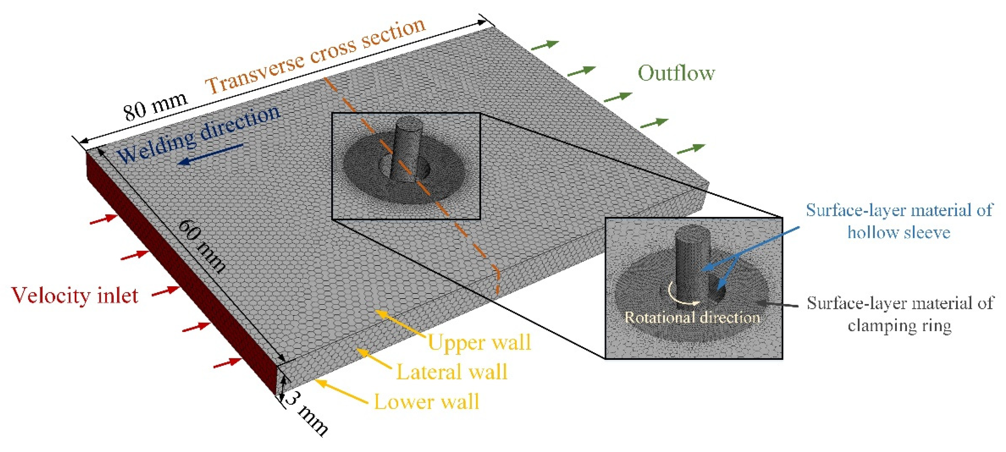
2.2. Finite Element Model of the N-KFSW Process

In order to better analyze the material flow behavior with different rotating sleeves, a finite element simulation was carried out by using the FLUENT® software (ANSYS2020R1, ANSYS Inc., Canonsburg, PA, USA) [21]. The dimensions of the fluid calculation domain were 80 mm × 60 mm × 3 mm. The welding tool was located in the center of a Cartesian rectangular coordinate system. To reduce the calculation steps and improve the calculation efficiency, 0.2 mm grids were selected at the position close to the tool, and 0.6 mm grids were selected at the position far away from the tool. The specific definition of the fluid domain is shown in Figure 2. In the simulation process, the material was considered as the fluid, which flowed into the calculation area through the velocity inlet and then flowed out of the pressure outlet with the same welding speed. In addition, the surface grids of the sleeve were set as the rotating wall; the upper, lateral and lower walls of flow model are described using the slip condition.
The density of the BM in the flow field was 2765 kg/m3, and the variation of specific heat capacity and thermal conductivity with temperature is shown in Table 2. In this study, the effects of temperature and strain rate on the viscosity coefficient of the BM were considered. The relationship between the material viscosity and the temperature, stress and strain was calculated by the following equation [22], and was imported into the FLUENT® software by using the UDF function programming method:
μ = σ ( T ,   ε ¯   ) 3   ε ¯
where μ , σ and ε ¯ , respectively, represent the material viscosity, the material rheological stress and the material strain rate; the material flow stress was calculated by the Zener–Hollomon equation, which is widely used to solve the hydrodynamic model of material flow in FSW. This equation is:
σ = 1 α ln { ( Z A ) 1 n + [ ( Z A ) 2 n + 1 ] 1 2 }
where α, ln(A) and n are constants related to the material, whose values are, respectively, 0.024 Pa−1, 27.42 s−1 and 4.62; Z is the Zener–Hollomon coefficient, and its calculation equation is:
Z ( T , ε ¯ ) = ε ¯ exp ( Q R T )
where Q is the activation energy, whose value is 234,000 J/mol, and R is the gas constant, whose value is 8.314 J/(mol·K).

3. Results

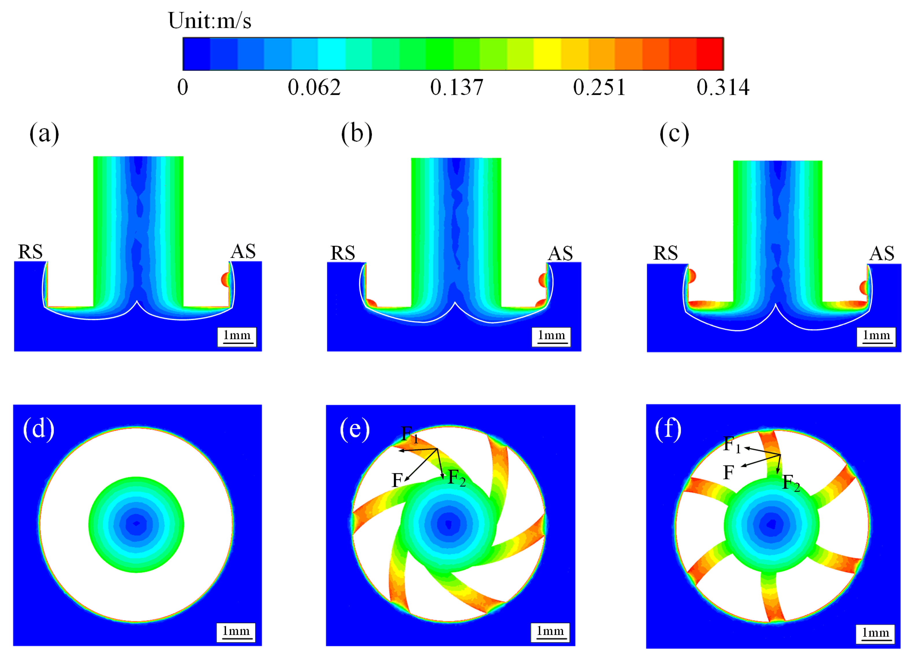
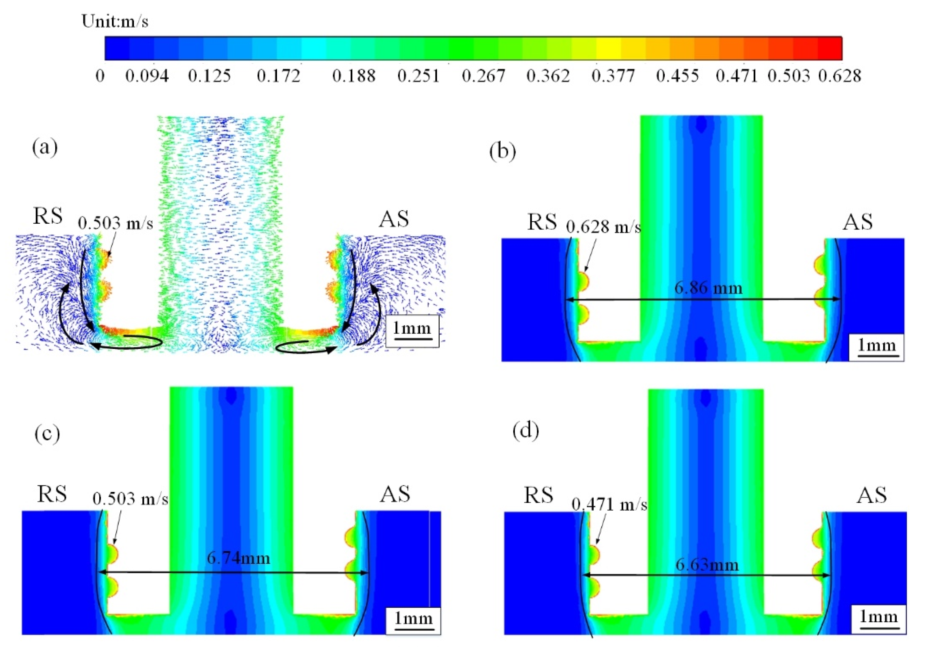
3.1. Material Flow by Optimized Sleeves and Experimental Verification

In order to compare the advantages of the three sleeve structures, numerical simulations of the material flow were performed at a plunging depth of the sleeve of 1.5 mm, and the results are displayed in Figure 3. Figure 3a–c show the material flow contours of a cross section. According to the continuity law of fluid [24], the groove on the tool can accelerate the flowing of the material into the groove. Thus, the region with the groove along the side wall of the sleeve presents a higher material flow velocity than other regions [25]. During welding, the rotational velocity and diameter of the tool directly influence the material flow velocity [26], and the flow velocity of the material contacting the tool increases with the increase of the tool diameter and of the rotational velocity. The pin of the used tool (Figure 1) in this study was cylindrical, there was no rotating shoulder, and the spiral groove on the sleeve bottom accelerated the material flow. Therefore, the material flow velocity at the plate top was lower than that at the plate bottom, while the material flow velocity at the sleeve edge was higher than that at the sleeve center (Figure 3a–c). Figure 3d–f display the material flow contours parallel to the plate top surface at the position of 1.6 mm from the plate bottom. According to Reference [27], the plasticized material flowing into the spiral groove is subjected to two forces. One is the positive pressure (F2) provided by the side wall of the spiral groove, and the other is the friction force (F1) between the material and the side wall of the spiral groove. The resultant force (F) of F1 and F2 makes the plasticized material not only rotate around the axis of the rotational tool but also move toward the axis of the rotational tool. Compared with the RF sleeve, in the RE sleeve, the angle between the spiral groove and the sleeve inner side wall is larger, thereby driving more materials toward the axis of the rotational tool. After the materials accumulate in the center region under the sleeve bottom, they mainly move downward according to the law of minimum resistance [28]. Therefore, compared with the RF sleeve, the RE sleeve has a better ability of accumulating materials at the center under the sleeve bottom, thereby better enhancing the material flow in the thickness direction. In brief, the existence of a groove on the sleeve bottom accelerates the material flow; the RE sleeve, with a larger angle between the spiral groove and the sleeve inner side wall, is more efficient than the RN sleeve and the RF sleeve from the viewpoint of improving the material flow behavior along the plate thickness.
In order to verify the correctness of the numerical simulation, cross sections of the joints after welding at a plunge depth of 1.5 mm, rotational velocity of 1000 rpm and welding speed of 50 mm/min were observed, as shown in Figure 4. The advancing side (AS) and the retreating side (RS) are marked in Figure 4. It was seen that part of the butt interface still appeared near the plate bottom, which was because the 1.5 mm plunge depth was much smaller than the plate thickness of 3 mm. The part of the butt interface was bent in the rotation direction by the stirring action of the sleeve, thus forming a C-shaped line. With the increase of the distance away from the plate bottom, the bending degree of the C-shaped line increased because the stirring effect of the sleeve was enhanced. The cross section was divided into the stir zone (SZ), the thermo-mechanically affected zone (TMAZ), the heat-affected zone (HAZ) and the BM, and these four zones were distinguished according to the grain size and morphology [29]. The C-shaped line heights in the cross sections by the RN, RF and RE sleeves were 0.78, 0.67 and 0.59 mm, respectively. Thus, the distances between the sleeve bottom and the top of the C-shaped line were, respectively, 0.72, 0.83 and 0.91 mm with the RN, RF and RE sleeves. These large distance values showed that the sleeve with a hollow part could effectively avoid the incomplete root penetration defect of the butt joint by FSW, as also reported by Gong et al. [16]. Moreover, the height of the C-shaped line is closely related to the ability to drive the material to the sleeve bottom. This ability increases as the height of the C-shaped line becomes smaller and the distance between the sleeve bottom and the top of the C-shaped line becomes larger. From the experimental results in Figure 4, it was known that the six-spiral grooves on the RF and RE sleeves bottom helped the elimination of the C-shaped line, and this effect was better with the RE sleeve than with the RF sleeve, which verified the validities of the numerical simulation results shown in Figure 3 and the rationality of the FE model established in this study.

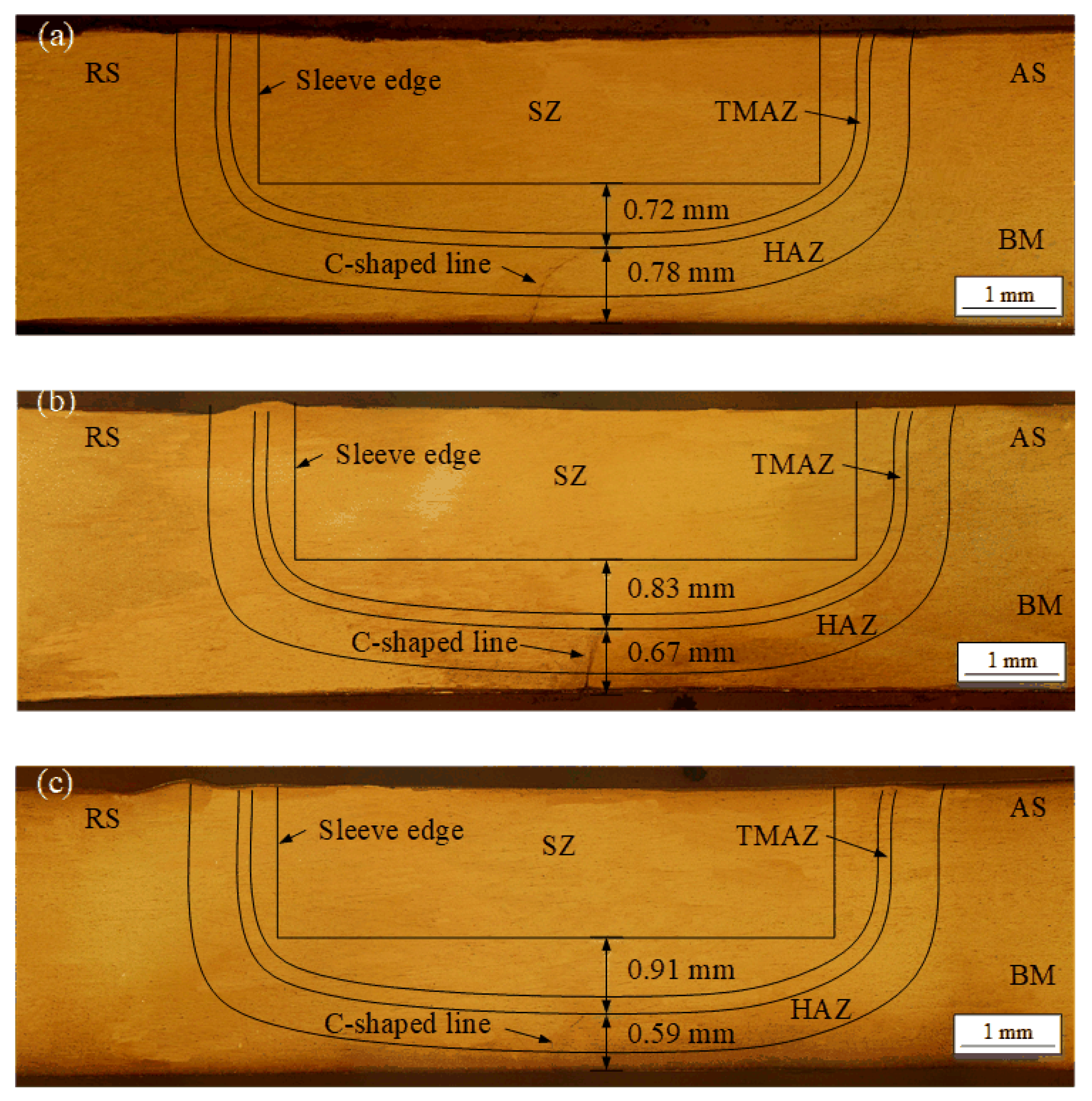
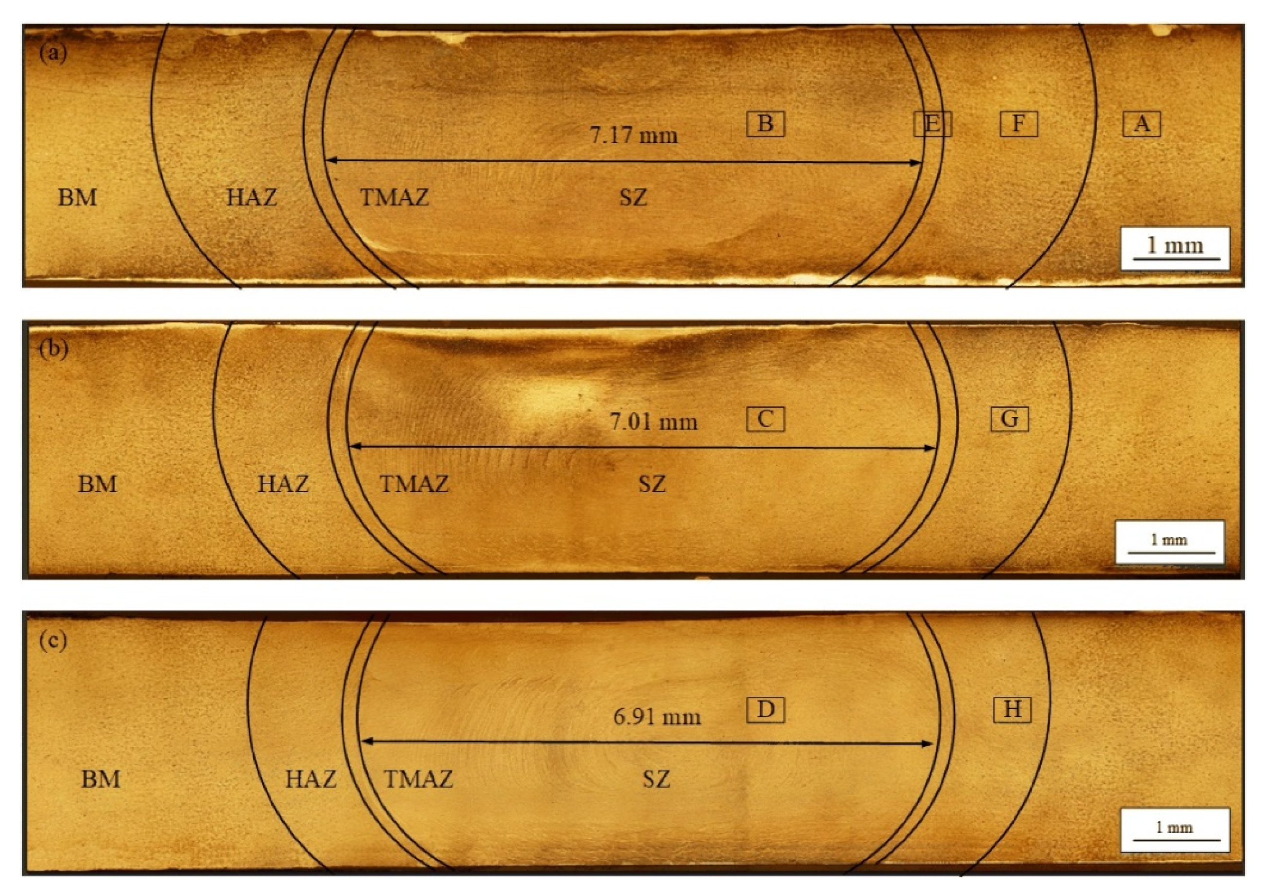
3.2. Effect of the Welding Speed on the RE Sleeve Ioints
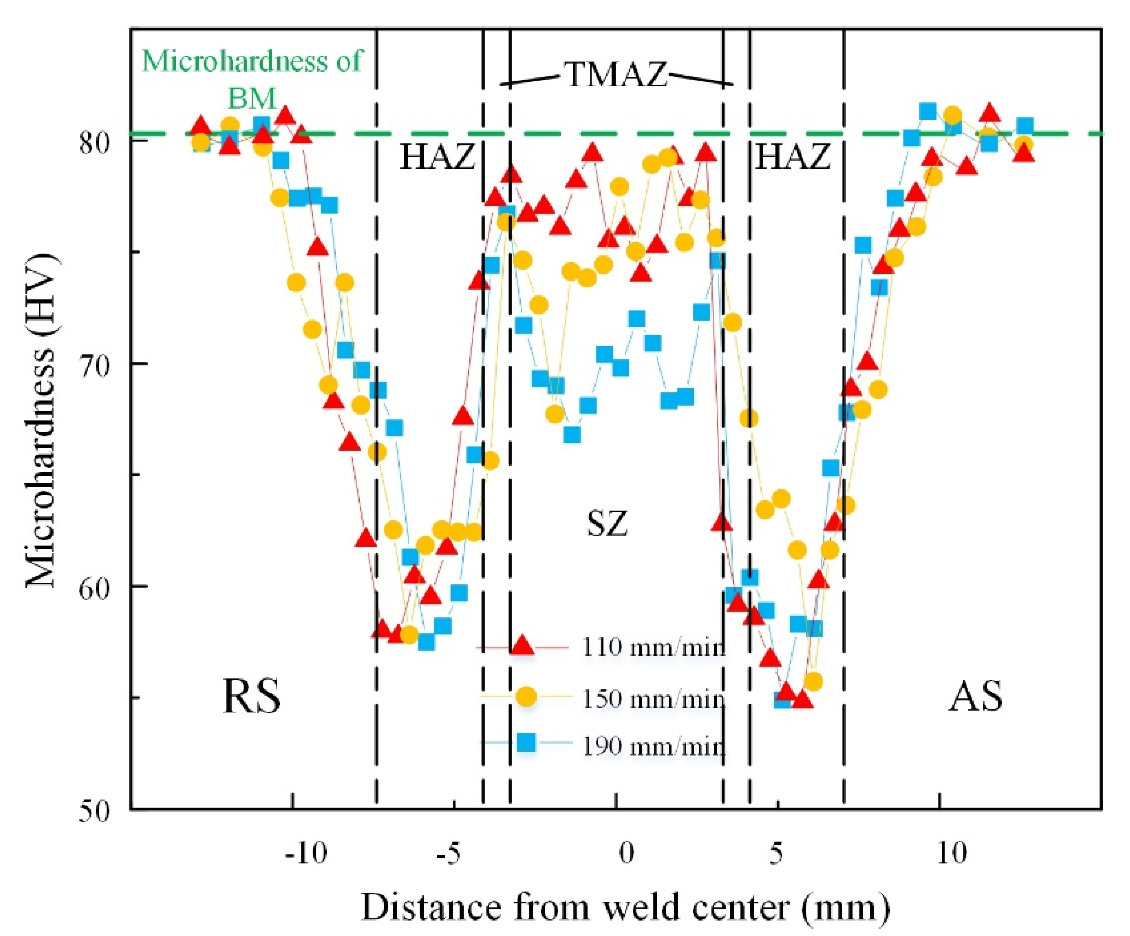
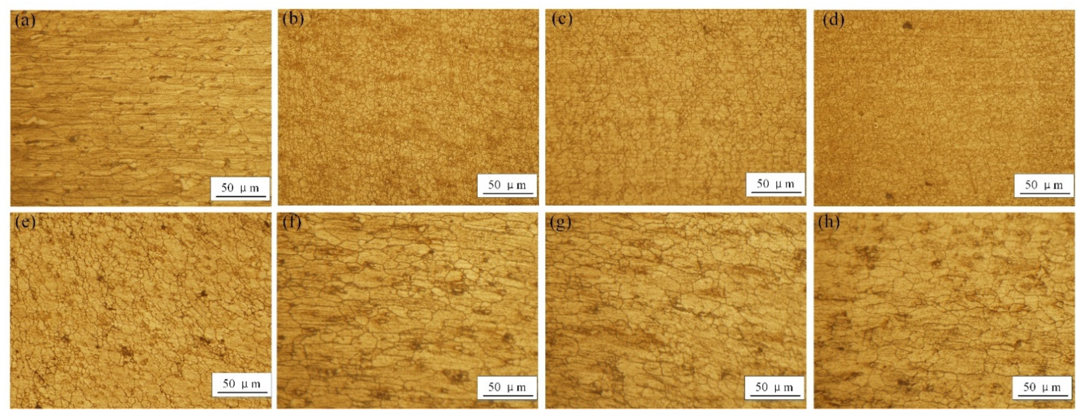
By comparing three different sleeve bottom structures through the above numerical and experimental results, the RE sleeve appeared to have the optimum sleeve bottom structure. Therefore, the RE sleeve was used in this study to investigate the N-KFSW joints under different welding speeds. During the N-KFSW process, the material flow has a dominant influence on joint formation. Thus, we investigated how the welding speed influenced the material flow behavior, and the results are displayed in Figure 5. Figure 5a displays the cross-sectional material flow velocity vectors at the welding speed of 150 mm/min. When the RE sleeve rotated anticlockwise, the right-hand thread on the side wall of the sleeve facilitated the contact between the material and the sleeve and its flow from the sleeve top to the sleeve bottom [30], which caused the material to accumulate at the sleeve bottom. The accumulated material at the sleeve bottom flowed from the edge of the sleeve bottom to the center of the sleeve bottom under the action of the spiral groove on the sleeve bottom, thereby improving the material flow behavior near the butt interface of the joint bottom. Figure 5b–d show the cross-sectional material flow contours with the RE sleeve under different welding speeds. For the welding tool owning a rotating shoulder, the maximum material flow velocity during FSW was always located at the edge of the rotating shoulder. However, the maximum material flow velocity in this study was mainly located on the sleeve side wall in the red area because the used welding tool in Figure 1 did not have a rotating shoulder. With the welding speed increased, the maximum material flow velocity decreased. When the welding speeds of 110, 150 and 190 mm/min were used, the maximum values were, respectively, 0.628, 0.549 and 0.471 m/s. Moreover, the width of the area with the highest flow velocity was measured, and the measured position was 1.5 mm from the top surface of the joint (Figure 5b–d). With the RE sleeve, these widths were 6.86, 6.74 and 6.63 mm when the welding speeds were 110, 150 and 190 mm/min, respectively. As the welding speed increased, the welding temperature decreased, and then the flow stress of the material heightened, resulting in the lowest maximum material flow velocity and the smallest width of the area with a high flow velocity.
The plunge depth of the rotational tool is always smaller than the plate thickness to avoid damage to the rotational tool pin. Nevertheless, an incomplete root penetration defect may occur at the butt joint bottom, thus weakening the tensile performance of the FSW joint [31]. In fact, this defect can be easily avoided using the RE sleeve with a hollow part (Figure 1b,e). Figure 6 shows the cross sections of the joints at different welding speeds and constant plunge depth of 2.7 mm and rotational velocity of 2000 rpm. Further observation of zones A, B, C, D, E, F, G, and H was performed, and SZ, HAZ, TMAZ, and BM typical microstructures were obtained (Figure 7). Meanwhile, the clamping ring acted as a stationary shoulder and exerted a downward axial force, preventing the material from flowing out of plate [7]. The sleeve was rotational and had threads on the side wall to allow the material to flow violently, so the SZ acquired a drum shape. The SZ widths were measured at different welding speeds, with the measured line 1.5 mm from the top surface of the plate. When the welding speeds were 110, 150 and 190 mm/min, the SZ widths were 7.17, 7.01 and 6.91 mm, respectively. This decreasing width was related to the decreased heat input and sleeve stirring action. Certainly, the changing SZ width with changes in the welding speed was consistent with the simulation results and confirmed the correctness of the simulation results. In addition, an onion ring structure appeared in the SZ due to sufficient material flow [15], and the onion rings became more defined as the welding speed decreased.
The typical microstructures of the joint are shown in Figure 7. The grain size in different areas was calculated based on the linear intercept method, similar to the study of Bagheri et al. [32]. The grains in the rolled BM showed an elongated lath shape along the rolling direction (Figure 7a), and the average grain size was 9.46 ± 0.37 μm. The RE sleeve was the main heat-generating and mechanical stirring part, so the SZ experienced high thermal cycling and large deformation (Figure 7b–d). Thus, the SZ was composed of fine equiaxed grains due to dynamic recrystallization under high temperature and large strain. The average grain sizes of the SZs at 110, 150 and 190 mm/min welding speeds were, respectively, 4.55 ± 0.23, 6.25 ± 0.31 and 7.14 ± 0.36 μm (Figure 7b–d). The grain in TMAZ (Figure 7e) was distorted due to the indirect stirring action of the sleeve, and its size of 8.38 ± 0.33 μm indicated that incomplete dynamic recrystallization occurred under the influence of moderate thermal cycling and strain rate. The HAZ underwent only a low thermal cycle, and the grains in the HAZ were coarsened (Figure 7f–h) and larger than those of the BM; their sizes were 13.24 ± 0.37, 12.04 ± 0.36 and 10.59 ± 0.32 μm at the welding speeds of 110, 150 and 190 mm/min, respectively.

3.3. Microhardness

The joint microhardness distribution at different welding speeds is shown in Figure 8; the measurement line was 1.5 mm from the top surface of the joint. The microhardness in the BM was about 82 ± 4 HV. The microhardness of the joints had a “W”-shaped distribution, which is a typical distribution of age-hardenable aluminum-alloy FSW joints [29,33]. The zones including the SZ, TMAZ and HAZ experienced the highest temperature, so the corresponding microhardness values of the material were lower than those of the BM; this phenomenon is called softening of the material. According to the Hall–Petch relationship, the material microhardness increases with a decrease in grain size [34]. Thus, among the SZ, TMAZ and HAZ, the SZ showed the highest microhardness, whereas the microhardness of the HAZ was the lowest. As mentioned above, the grain size in the SZ increased as the welding speed increased, so increasing the welding speed led to an SZ with higher microhardness; the microhardness value of 80.4 HV in the SZ was the highest. Moreover, the HAZ at the advancing side (AS) showed a microhardness lower than that at the retreating side (RS), because the temperature peak at the AS during welding was higher than that at the RS [35]. Sankara et al. [36] reported that increasing the welding speed decreased the welding temperature during welding. Therefore, compared with the joints at 150 and 190 mm/min welding speed, the joint at 110 mm/min welding speed presented not only a larger area undergoing the softening phenomenon, but also a larger softening degree of the material.

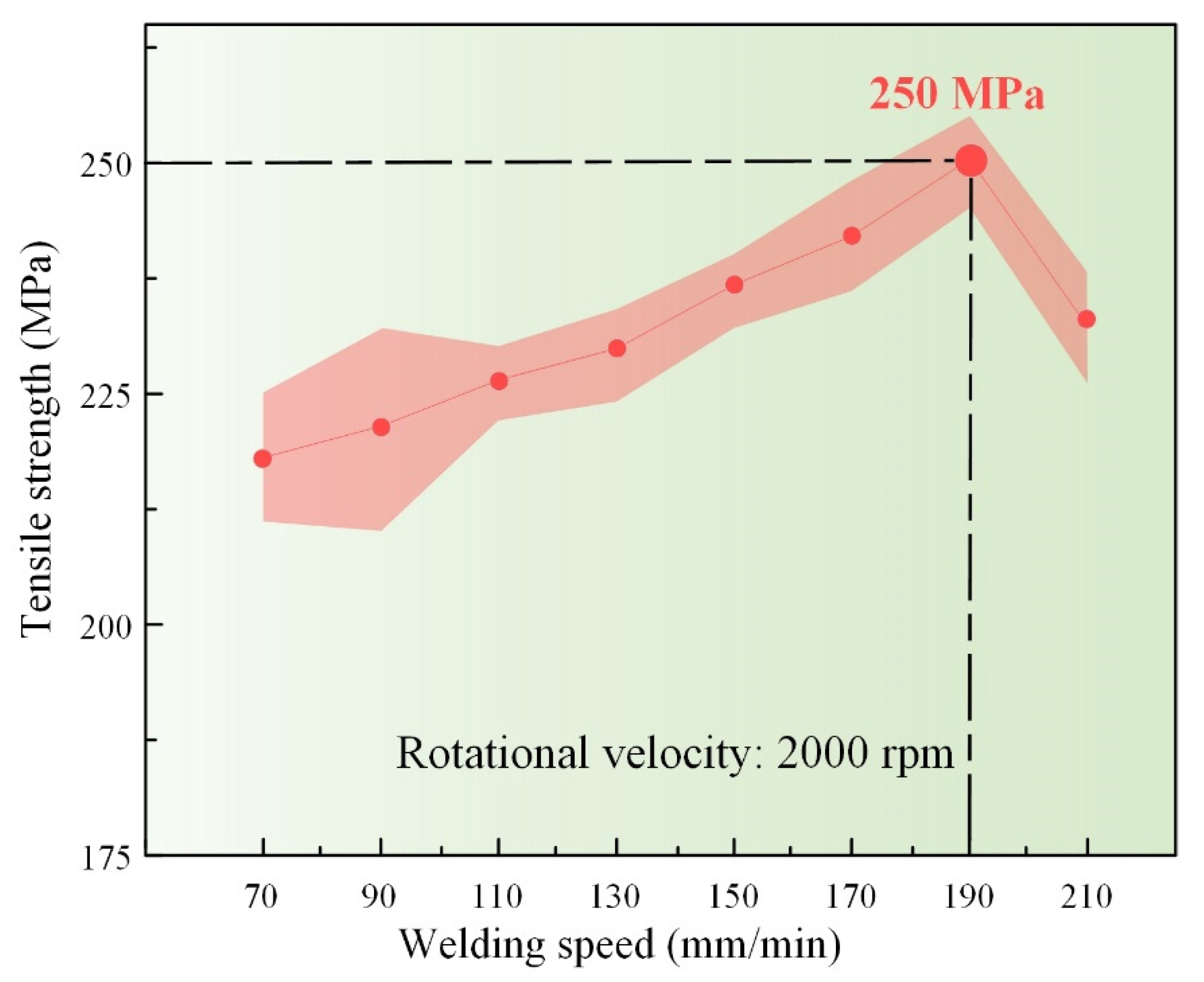
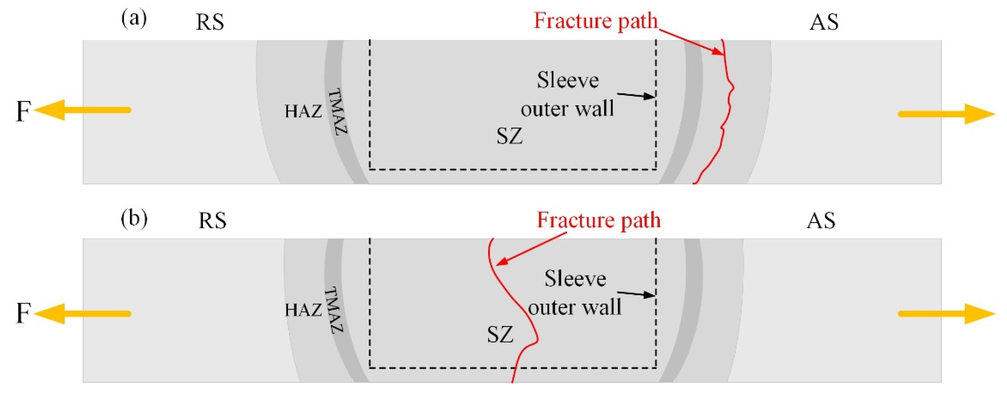
3.4. Tensile Properties and Fracture Characteristics

The tensile strengths (TSs) of the joints at different welding speeds are shown in Figure 9. The TS increased and then decreased as the welding speed increased from 70 mm/min to 210 mm/min. The maximum TS of 250 MPa was obtained at 190 mm/min, and this value reaches 70.5% of that of the BM. The advancing side (AS) and the retreating side (RS) are marked in Figure 10. Two different fracture types were observed after the tensile test, as shown in Figure 10. Type I fracture consisted in joint fractures in the HAZ (Figure 10a), while type II involved joint fractures in the SZ (Figure 10b). The fracture type was determined by the stirring action of the sleeve and the softening degree in the HAZ. Under welding speeds from 70 mm/min to 190 mm/min, the HAZ softened severely because of frictional heat; therefore the HAZ was the weakest area of the welding joint. The microhardness value of the HAZ was the lowest at the AS (Figure 8), so the crack initiated and extended along the HAZ until the joint fractured. With increasing welding speed, the welding temperature of the SZ and the stirring effect of the sleeve were both reduced, which always led to a kissing bond defect in the SZ. Therefore, when the welding speed further increased from 190 mm/min to 210 mm/min, the weak region in the joint moved from the HAZ to the SZ, and the TS of joint decreased to 232 MPa from 250 MPa.

4. Conclusions

In this study, the sleeve bottoms of an N-KFSW welding tool system were optimized, and numerical simulations were performed and verified the correctness of the simulation. Then, the joints of an Al–Mg–Si alloy by with optimal sleeve structure were obtained at different welding speeds, and the material flow, microstructure and mechanical properties were studied. The following conclusions were drawn:
(1)
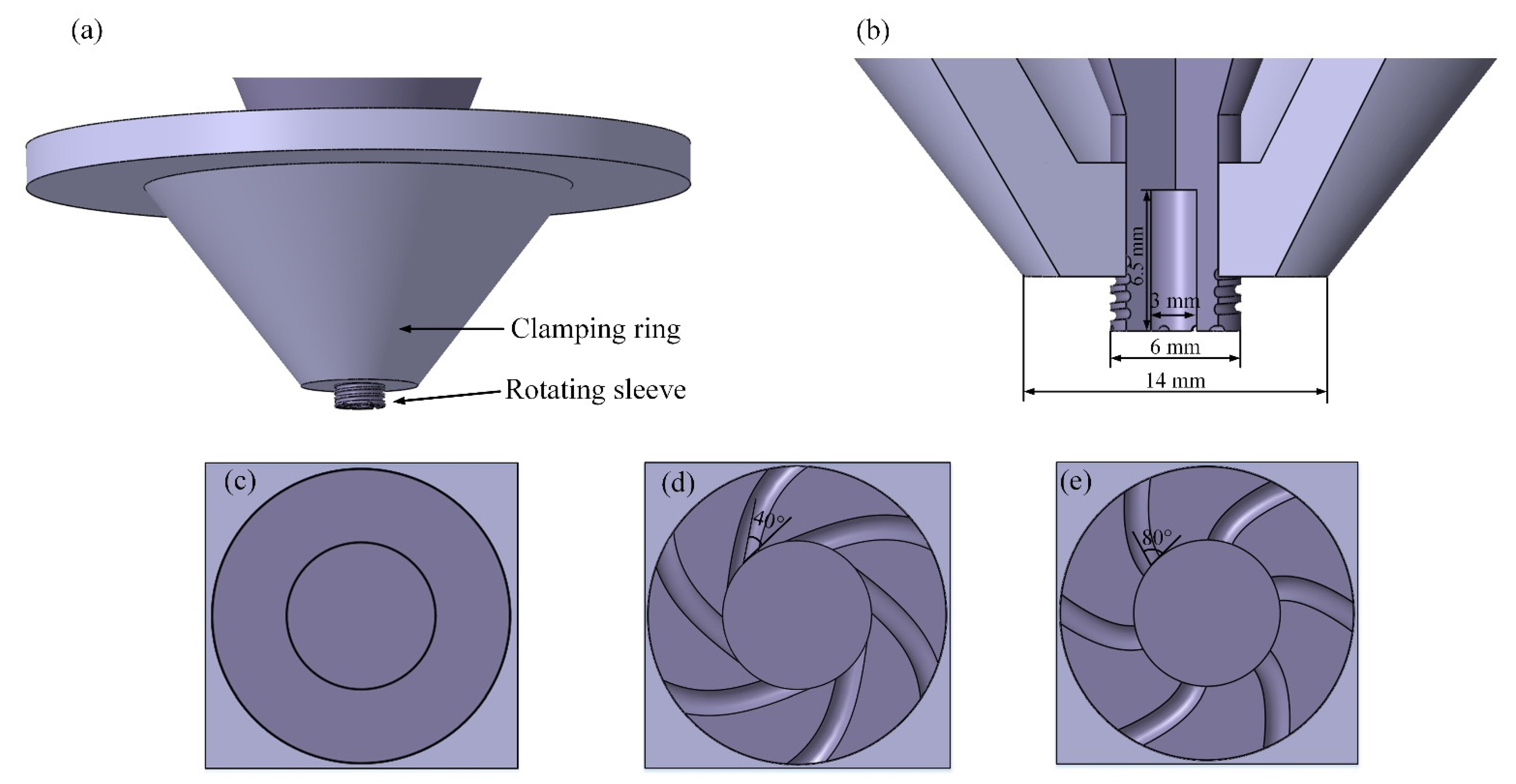
The six-spiral grooves on the sleeve bottom enhanced the material flow effectively in the thickness direction. A large angle between the spiral groove and the sleeve inner side wall was better from the viewpoint of improving the material flow in the thickness direction and could effectively avoid the incomplete root penetration defect at the SZ bottom.
(2)
The SZ of the N-KFSW joint presented a drum shape due to the action of the clamping ring and the threads on the side wall of the sleeve. Its width decreased as the welding speed increased. The microhardness distribution showed that the joint at 110 mm/min welding speed presented not only a larger softening area, but also a larger softening degree of the material compared with the joints at 150 and 190 mm/min welding speed.
(3)
When the welding speed varied from 70 mm/min to 210 mm/min, the joint strength increased and then decreased. The maximum joint tensile strength was 250 MPa at 190 mm/min, and its corresponding fracture path was located at the HAZ. The joint with lower strength fractured at the SZ due to a lower heat input at a higher welding speed.

Author Contributions

Y.L. and Z.S., contributed equally to this work. Conceptualization, S.J., Z.J. and Z.S.; methodology, Y.L. and X.Q.; software, Z.S. and Y.Z.; formal analysis, S.J., Y.L. and F.L.; writing—original draft preparation, Z.S., S.J., Z.J. and Y.L.; writing—review and editing, Z.S., S.J., Z.J. and Y.L. All authors have read and agreed to the published version of the manuscript.

Funding

This research received no external funding.

Data Availability Statement

Not applicable.

Conflicts of Interest

The authors declare no conflict of interest.

References

  1. Bokov, D.O.; Jawad, M.A.; Suksatan, W.; Abdullah, M.E.; Świerczyńska, A.; Fydrych, D.; Derazkola, H.A. Effect of pin shape on thermal history of aluminum-steel friction stir welded joint: Computational fluid dynamic modeling and validation. Materials 2021, 14, 7883. [Google Scholar] [CrossRef]
  2. Chitturi, V.; Pedapati, S.R.; Awang, M. Mathematical Model for Friction Stir Lap Welded AA5052 and SS304 Joints and Process Parameters Optimization for High Joint Strength. Adv. Mater. Sci. 2022, 22, 5–22. [Google Scholar] [CrossRef]
  3. Meng, X.; Huang, Y.; Cao, J.; Shen, J.; dos Santos, J.F. Recent progress on control strategies for inherent issues in friction stir welding. Prog. Mater. Sci. 2021, 115. [Google Scholar] [CrossRef]
  4. Liu, Z.; Meng, X.; Ji, S.; Li, Z.; Wang, L. Improving tensile properties of Al/Mg joint by smashing intermetallic compounds via ultrasonic-assisted stationary shoulder friction stir welding. J. Manuf. Process. 2018, 31, 552–559. [Google Scholar] [CrossRef]
  5. Eslami, S.; Ramos, T.; Tavares, P.J.; Moreira, P.M.G.P. Shoulder design developments for FSW lap joints of dissimilar polymers. J. Manuf. Process. 2015, 20, 15–23. [Google Scholar] [CrossRef]
  6. Li, D.; Yang, X.; Cui, L.; He, F.; Zhang, X. Investigation of stationary shoulder friction stir welding of aluminum alloy 7075-T651. J. Mater. Process. Technol. 2015, 222, 391–398. [Google Scholar] [CrossRef]
  7. Barbini, A.; Carstensen, J.; dos Santos, J.F. Influence of a non-rotating shoulder on heat generation, microstructure and mechanical properties of dissimilar AA2024/AA7050 FSW joints. J. Mater. Sci. Technol. 2018, 34, 119–127. [Google Scholar] [CrossRef]
  8. Wu, H.; Chen, Y.-C.; Strong, D.; Prangnell, P. Stationary shoulder FSW for joining high strength aluminum alloys. J. Mater. Process. Technol. 2015, 221, 187–196. [Google Scholar] [CrossRef]
  9. Ji, H.; Deng, Y.; Xu, H.; Lin, S.; Wang, W.; Dong, H. The mechanism of rotational and non-rotational shoulder affecting the microstructure and mechanical properties of Al-Mg-Si alloy friction stir welded joint. Mater. Des. 2020, 192. [Google Scholar] [CrossRef]
  10. Du, B.; Yang, X.; Liu, K.; Sun, Z.; Wang, D. Effects of supporting plate hole and welding force on weld formation and mechanical property of friction plug joints for AA2219-T87 friction stir welds. Weld. World. 2019, 63, 989–1000. [Google Scholar] [CrossRef]
  11. Huang, Y.X.; Han, B.; Tian, Y.; Liu, H.J.; Lv, S.X.; Feng, J.C.; Leng, J.S.; Li, Y. New technique of filling friction stir welding. Sci. Technol. Weld. Join. 2013, 16, 497–501. [Google Scholar] [CrossRef]
  12. Ji, S.D.; Meng, X.C.; Huang, R.F.; Ma, L.; Gao, S.S. Microstructures and mechanical properties of 7N01-T4 aluminum alloy joints by active-passive filling friction stir repairing. Mater. Sci. Eng. A 2016, 664, 94–102. [Google Scholar] [CrossRef]
  13. Zhou, L.; Liu, D.; Nakata, K.; Tsumura, T.; Fujii, H.; Ikeuchi, K.; Michishita, Y.; Fujiya, Y.; Morimoto, M. New technique of self-refilling friction stir welding to repair keyhole. Sci. Technol. Weld. Join. 2013, 17, 649–655. [Google Scholar] [CrossRef]
  14. Ding, R.J.; Oelgoetz, P.A. Auto-Adjustable Pin Tool for Friction Stir Welding. U.S. Patent 5,893,507, 13 April 1999. [Google Scholar]
  15. Gong, P.; Zuo, Y.; Ji, S.; Yan, D.; Shang, Z. A novel non-keyhole friction stir welding process. J. Manuf. Proc. 2022, 73, 17–25. [Google Scholar] [CrossRef]
  16. Gong, P.; Zuo, Y.-Y.; Ji, S.-D.; Yan, D.-J.; Li, D.-C.; Shang, Z. Non-keyhole Friction Stir Welding for 6061-T6 Aluminum Alloy. Acta Metall. Sin.-Engl. 2021, 35, 763–772. [Google Scholar] [CrossRef]
  17. Chen, C.; Xiao, Z.; Xue, G.; Liao, H.; Zhu, H. Distribution and evolution of thermal stress in laser powder bed fusion: Conduction mode versus keyhole mode. Rapid Prototyp. J. 2022, 28, 1325–1345. [Google Scholar] [CrossRef]
  18. Khorasani, M.; Ghasemi, A.; Leary, M.; Sharabian, E.; Cordova, L.; Gibson, I.; Downing, D.; Bateman, S.; Brandt, M.; Rolfe, B. The effect of absorption ratio on meltpool features in laser-based powder bed fusion of IN718. Opt. Laser Technol. 2022, 153, 108263. [Google Scholar] [CrossRef]
  19. Lv, J.; Shen, H.; Fu, J. Effects of the process parameters on the formability and properties of Ni54(at.%) Ti alloys prepared by laser powder bed fusion. Rapid Prototyp. J. 2022, 28, 1193–1205. [Google Scholar] [CrossRef]
  20. Panahizadeh, V.; Ghasemi, A.H.; Dadgar Asl, Y.; Davoudi, M. Optimization of LB-PBF process parameters to achieve best relative density and surface roughness for Ti6Al4V samples: Using NSGA-II algorithm. Rapid Prototyp. J. 2022; ahead-of-print. [Google Scholar] [CrossRef]
  21. Kadian, A.K.; Biswas, P. The study of material flow behaviour in dissimilar material FSW of AA6061 and Cu-B370 alloys plates. J. Manuf. Process. 2018, 34, 96–105. [Google Scholar] [CrossRef]
  22. Hasan, A.F. CFD modelling of friction stir welding (FSW) process of AZ31 magnesium alloy using volume of fluid method. J. Mater. Res. Technol. 2019, 8, 1819–1827. [Google Scholar] [CrossRef]
  23. Huang, Y.; Xie, Y.; Meng, X.; Lv, Z.; Cao, J. Numerical design of high depth-to-width ratio friction stir welding. J. Mater. Process. Technol. 2018, 252, 233–241. [Google Scholar] [CrossRef]
  24. Ji, S.D.; Shi, Q.Y.; Zhang, L.G.; Zou, A.L.; Gao, S.S.; Zan, L.V. Numerical simulation of material flow behavior of friction stir welding influenced by rotational tool geometry. Comp. Mater. Sci. 2012, 63, 218–226. [Google Scholar] [CrossRef]
  25. Ke, W.C.; Oliveira, J.P.; Ao, S.S.; Teshome, F.B.; Chen, L.; Peng, B.; Zeng, Z. Thermal process and material flow during dissimilar double-sided friction stir spot welding of AZ31/ZK60 magnesium alloys. J. Mater. Res. Technol. 2022, 17, 1942–1954. [Google Scholar] [CrossRef]
  26. Yang, C.; Dai, Q.; Shi, Q.; Wu, C.; Zhang, H.; Chen, G. Flow-coupled thermo-mechanical analysis of frictional behaviors at the tool-workpiece interface during friction stir welding. J. Manuf. Process. 2022, 79, 394–404. [Google Scholar] [CrossRef]
  27. Ji, S.; Meng, X.; Zeng, Y.; Ma, L.; Gao, S. New technique for eliminating keyhole by active-passive filling friction stir repairing. Mater. Des. 2016, 97, 175–182. [Google Scholar] [CrossRef]
  28. Liu, H.; Liu, Z.; Ji, S.; Yue, Y.; Dong, Z.; Chen, C. Active-passive radial-additive friction stir repairing of mechanical hole out of dimension tolerance of AZ31 magnesium alloy. J. Magnes. Alloys 2022. [Google Scholar] [CrossRef]
  29. Sree Sabari, S.; Malarvizhi, S.; Balasubramanian, V. Characteristics of FSW and UWFSW joints of AA2519-T87 aluminium alloy: Effect of tool rotation speed. J. Manuf. Process. 2016, 22, 278–289. [Google Scholar] [CrossRef]
  30. Jiang, T.; Wu, C.; Shi, L. Effects of tool pin thread on temperature field and material mixing in friction stir welding of dissimilar Al/Mg alloys. J. Manuf. Process. 2022, 74, 112–122. [Google Scholar] [CrossRef]
  31. Zhang, L.; Ji, S.; Luan, G.; Dong, C.; Fu, L. Friction Stir Welding of Al Alloy Thin Plate by Rotational Tool without Pin. J. Mater. Sci. Technol. 2011, 27, 647–652. [Google Scholar] [CrossRef]
  32. Bagheri, B.; Abbasi, M. Development of AZ91/SiC surface composite by FSP: Effect of vibration and process parameters on microstructure and mechanical characteristics. Adv. Manuf. 2020, 8, 82–96. [Google Scholar] [CrossRef]
  33. Azeez, S.T.; Akinlabi, E.T. Effect of processing parameters on microhardness and microstructure of a double-sided dissimilar friction stir welded aa6082-t6 and aa7075-t6 aluminum alloy. Mater. Today Proc. 2018, 5, 18315–18324. [Google Scholar] [CrossRef]
  34. Kalinenko, A.; Kim, K.; Vysotskiy, I.; Zuiko, I.; Malopheyev, S.; Mironov, S.; Kaibyshev, R. Microstructure-strength relationship in friction-stir welded 6061-T6 aluminum alloy. Mater. Sci. Eng. A 2020, 793, 139858. [Google Scholar] [CrossRef]
  35. Peng, C.; Jing, C.; Siyi, Q.; Siqi, Z.; Shoubo, S.; Ting, J.; Zhiqing, Z.; Zhihong, J.; Qing, L. Friction stir welding joints of 2195-T8 Al–Li alloys: Correlation of temperature evolution, microstructure and mechanical properties. Mater. Sci. Eng. A 2021, 823, 141501. [Google Scholar] [CrossRef]
  36. Rao, C.J.; Aadapa, S.K.; Yanda, S. Predication of temperature distribution and strain during FSW of dissimilar Aluminum alloys using Deform 3D. Mater. Today Proc. 2022, 59, 1760–1767. [Google Scholar] [CrossRef]
Figure 1. Simplified N-KFSW tool: (a) combination, (b) section; three different surface morphologies of the sleeve bottom: (c) RN sleeve bottom, (d) RF sleeve bottom and (e) RE sleeve bottom.
Metals 12 01415 g001
Figure 2. Mesh generation and boundary conditions used in the simulation.
Metals 12 01415 g002
Figure 3. Material flow contours of a cross section with (a) RN sleeve, (b) RF sleeve and (c) RE sleeve; flow contours 1.6 mm from the plate bottom with (d) RN sleeve, (e) RF sleeve and (f) RE sleeve.
Metals 12 01415 g003
Figure 4. Cross sections of joints with (a) RN sleeve, (b) RF sleeve and (c) RE sleeve.
Metals 12 01415 g004
Figure 5. (a) Material flow velocity vectors at 150 mm/min welding speed; material flow contours at (b) 110 mm/min, (c) 150 mm/min and (d) 190 mm/min welding speeds.
Metals 12 01415 g005
Figure 6. Cross sections with the RE sleeve under different welding speeds: (a) 110 mm/min, (b) 150 mm/min and (c) 190 mm/min.
Metals 12 01415 g006
Figure 7. Typical microstructures at different welding speeds: (a) BM, (b) SZ at 110 mm/min, (c) SZ at 150 mm/min, (d) SZ at 190 mm/min, (e) TMAZ at 110 mm/min, (f) HAZ at 110 mm/min, (g) HAZ at 150 mm/min and (h) HAZ at 190 mm/min.
Metals 12 01415 g007
Figure 8. Microhardness distribution at different welding speeds.
Metals 12 01415 g008
Figure 9. Tensile strength of joints at different welding speeds.
Metals 12 01415 g009
Figure 10. Schematics of the fracture paths of joints at (a) 110 mm/min and (b) 210 mm/min welding speed.
Metals 12 01415 g010
Table 1. Chemical composition and mechanical properties of the Al–Mg–Si alloy.
Chemical Compositions (mass %)Mechanical Properties
SiFeCuMnMgCrZnTiAlTensile Strength (MPa)Elongation (%)Hardness (HV)
1.000.510.210.090.950.120.060.03Bal.356 ± 1212 ± 182 ± 4
Table 2. Temperature-dependent properties of the Al–Mg–Si alloy [23].
Temperature
(°C)
Specific Heat
(J/kg·K)
Thermal Conductivity
(W/m·K)
20982201
100995203
2001007202
4001014195
6001042171
Publisher’s Note: MDPI stays neutral with regard to jurisdictional claims in published maps and institutional affiliations.

