
Quality Assessment of Laser Welding Dual Phase Steels


Abstract
:1. Introduction
- “An imperfection in welding is the lack of continuity or deviation in the defined geometry”;
- “A defect in welding is an inadmissible imperfection”.
- Cracks;
- Cavities/porosities;
- Solid inclusions;
- Penetration failure;
- Dimensional defects;
- Various defects.
2. Quality Assessment Pre-Welding: Virtual Prototype FEM Analysis
2.1. FEM Analysis
2.1.1. Thermal Model
2.1.2. Mechanical Model
2.1.3. Metallurgical Model
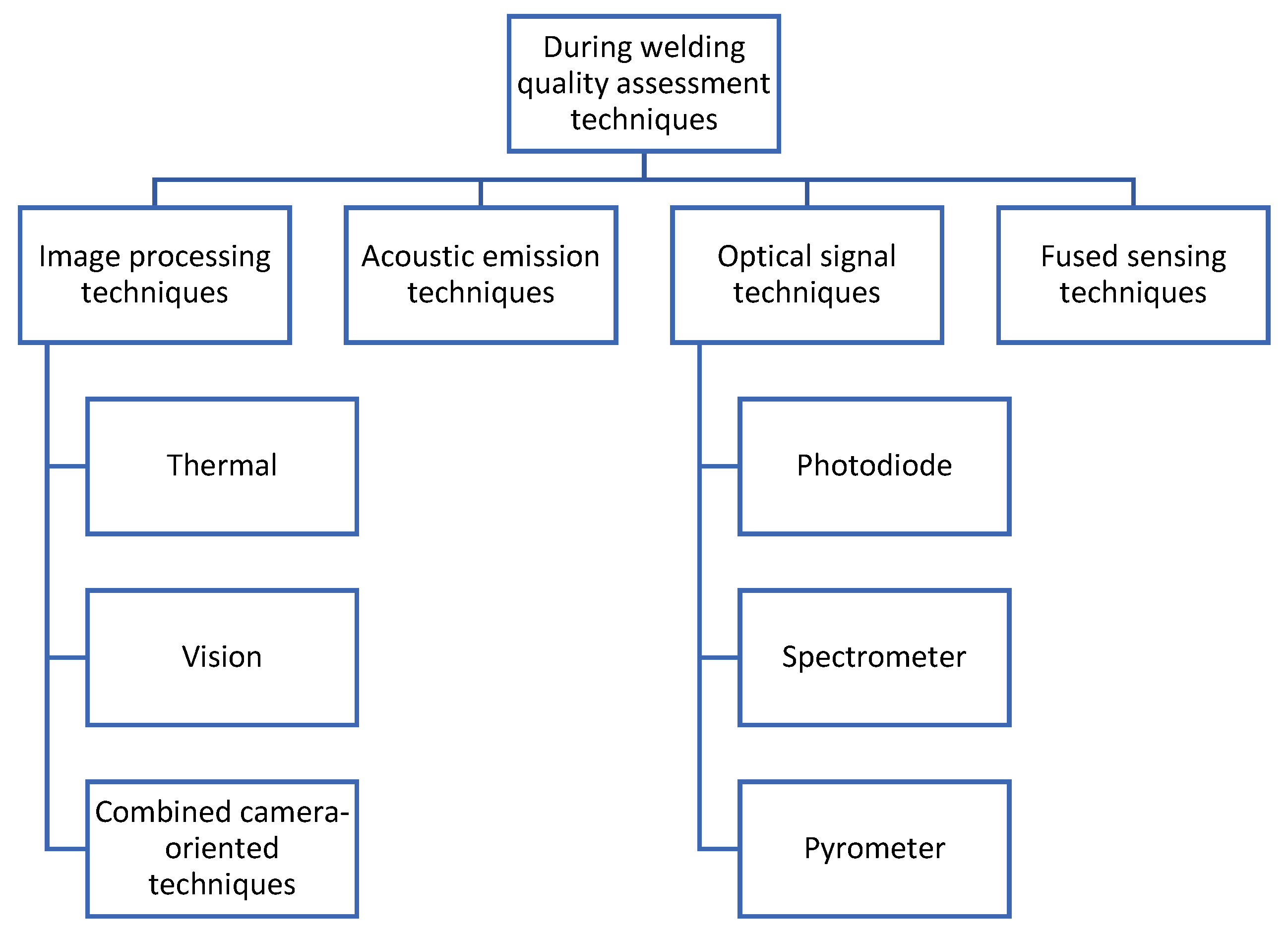
3. Quality Assessment during Welding
3.1. Image Processing Techniques
- Vision: with this method it is possible to characterize plasma plume, spatters and molten pool in welding. In the literature, there are papers in which a vision system was used together with vision sensor, based on the principle of triangulation in which it is possible to obtain information through 3D profiles. Some authors also used couple charged device (CCD) sensors to extract surface information, such as depth pool [39,40,41].
3.2. Acoustic Emission Techniques
3.3. Optical Techniques
3.4. Fused Techniques
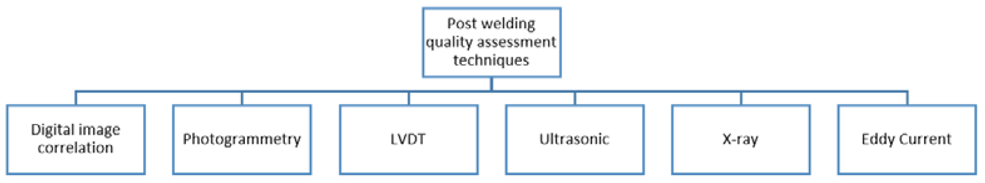
4. Quality Assessment Post-Welding
4.1. Digital Image Correlation (DIC)
4.2. Photogrammetry
4.3. Linear Variable Differential Transformer (LVDT)
4.4. Ultrasonic
4.5. X-ray Radiography
4.6. Eddy Current
4.7. Magneto-Optical Detection Method
5. Quality Assessment Considering Mechanical Properties
5.1. Hardness
- Growth of martensite in FZ:
- 2.
- Softening phenomenon in HAZ:
- HAZ softening has been associated with tempered martensite in the base metal.
- The width of soft zone decreases with increasing welding speed and decreasing beam width.
- It was also found in [96] that the appearance of fine-grained martensite in the subcritical HAZ results in an increased hardness, while the tempered martensite contributes to a soft zone.
- The size of the HAZ soft zone decreased with increasing pulse duration 83.
- In the work of [97], DP600, DP800 and DP1000 were studied, verifying that HAZ softening increased with steel grades, which is related to the amount of martensite in each type of DP steel.
- Pre Heat Welding Treatment:
- In [98], the study of DP980 steel welded at room temperature and preheated to 526 °C has been performed. Using preheating, it was observed that the microstructure in the FZ of the bead changed from martensitic (with a hardness between 320 and 500 HV) to a microstructure composed by bainite, ferrite and austenite, presenting 280 HV of hardness.
- Post-Welding Heat Treatment:
- In paper [85], two types of thermal treatments were tested with the purpose of resetting the initial characteristics of DP600 before welding. The hardness values in the welding and in the HAZ dropped significantly but still showed values 40% above the base metal. In paper [99], PWHT has been used in a DP1400 steel, and it was shown that the heat treatment had little significance regarding tensile strength due to the transformation of martensite into tempered martensite. However, it had relevant results with elongation, which contributes to lower defects, such as cold cracking.
- In the paper presented by [100], it was verified that using post-welding heat treatments, the tensile stress decreased from 725 ± 7 MPa to 679 ± 5 MPa, but the elongation increased from 2.8% to 3.5%.
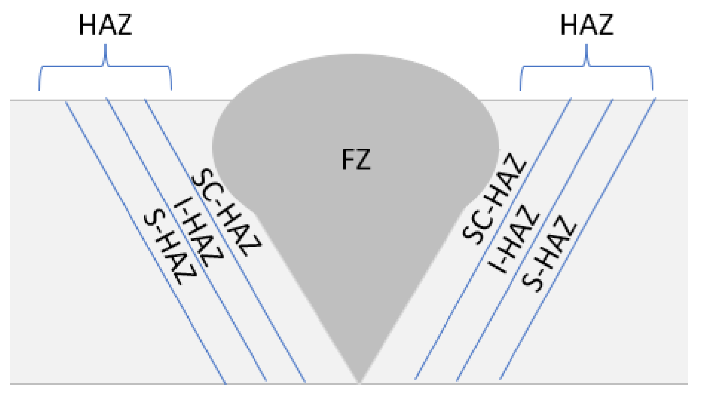
5.2. Microstructure
- Sub-critical HAZ (S-HAZ) is the region where the peak temperature during welding is below Ac1 temperature of steel phase diagram [101].
- It was verified by [101] that martensite in the BM was transformed into tempered martensite during subsequent heating and cooling, since the local temperature was below Ac1 and austenization did not take place.
- The martensite phase in the BM is tempered causing HAZ to soften. The severity of HAZ softening decreases with increasing distance from the Ac1 isotherm [82].
- Inter-critical HAZ (I-HAZ) is the region where the peak temperature during welding is between Ac1 and Ac3 temperature of steel phase diagram [101].
- It was verified by [101] that the local peak temperature was between Ac3 and Ac1; originating the austenitization of martensite and ferrite from BM and after cooling, it transformed into ferrite and M-A constituent.
- The volume fraction of martensite in the HAZ increases as the peak temperature rises from Ac1 to Ac3 [82].
- Super-critical or upper-critical HAZ (SC-HAZ): during welding, the steel is heated above Ac3 [101].
- The microstructure changes to austenite during heating. Depending on how high above Ac3 the temperature is, it can also occur grain growth. When the area of the HAZ with a temperature above Ac3 cools down, it transforms into martensite [82].
Effects of Laser Characteristics in Microstructure
- Heat input too high generates larger weld beads, promotes HAZ softening and leads to a less refined microstructure [104].
- Lower speed favours weld penetration but increase heat dissipation in the transverse direction to weld, which leads to wider welds.
- Constant welding speed increases welding width and penetration [103].
5.3. Tensile Properties
6. Discussion
7. Conclusions
Author Contributions
Funding
Institutional Review Board Statement
Informed Consent Statement
Data Availability Statement
Conflicts of Interest
References
- Pereira, A.B.; de Melo, F.J.M.Q. Quality Assessment and Process Management of Welded Joints in Metal Construction—A Review. Metals 2020, 10, 115. [Google Scholar] [CrossRef] [Green Version]
- DIN. V 4113-3:2003; Aluminium Constructions under Predominantly Static Loading—Part 3: Execution and Qualification of Constructors. German Institute for Standardization: Berlin, Germany, 2003.
- Toivanen, J.; Kah, P.; Martikainen, J. Quality Requirements and Conformity of Welded Products in the Manufacturing Chain in Welding Network. Int. J. Mech. Eng. Appl. 2015, 3, 109. [Google Scholar] [CrossRef] [Green Version]
- ISO 3834-3:2005; Quality Requirements for Fusion Welding of Metallic Materials—Part 3: Standard Quality Requirements. International Organization for Standardization: Geneva, Switzerland, 2005.
- ISO 6520-2:2013; Welding and Allied Processes—Classification of Geometric Imperfections in Metallic Materials, Part 2 Weld. International Organization for Standardization: Geneva, Switzerland, 2013.
- ISO 6520-1:2007; Welding and Allied Processes—Classification of Geometric Imperfections in Metallic Materials, Part 1 Fusion Welding. International Organization for Standardization: Geneva, Switzerland, 2007.
- Camilleri, D.; McPherson, N.; Gray, T.G. The applicability of using low transformation temperature welding wire to minimize unwanted residual stresses and distortions. Int. J. Press. Vessel. Pip. 2013, 110, 2–8. [Google Scholar] [CrossRef]
- Deng, D.; Murakawa, H.; Liang, W. Numerical simulation of welding distortion in large structures. Comput. Methods Appl. Mech. Eng. 2007, 196, 4613–4627. [Google Scholar] [CrossRef]
- Bachorski, A.; Painter, M.; Smailes, A.; Wahab, M. Finite-element prediction of distortion during gas metal arc welding using the shrinkage volume approach. J. Mater. Process. Technol. 1999, 92–93, 405–409. [Google Scholar] [CrossRef]
- Ghosh, B.P.K.; Devakumaran, K.P. Effect of Pulse Current on Shrinkage Stress and Distortion in Multipass GMA Welds of Different Groove Sizes. AWS 2010, 89, 43–53. [Google Scholar]
- Choobi, M.S.; Haghpanahi, M.; Sedighi, M. Prediction of welding-induced angular distortions in thin butt-welded plates using artificial neural networks. Comput. Mater. Sci. 2012, 62, 152–159. [Google Scholar] [CrossRef]
- Wang, J.; Shibahara, M.; Zhang, X.; Murakawa, H. Investigation on twisting distortion of thin plate stiffened structure under welding. J. Mater. Process. Technol. 2012, 212, 1705–1715. [Google Scholar] [CrossRef]
- Tian, L.; Luo, Y.; Wang, Y.; Wu, X. Prediction of transverse and angular distortions of gas tungsten arc bead-on-plate welding using artificial neural network. Mater. Des. 2014, 54, 458–472. [Google Scholar] [CrossRef]
- Deng, D.; Zhou, Y.; Bi, T.; Liu, X. Experimental and numerical investigations of welding distortion induced by CO2 gas arc welding in thin-plate bead-on joints. Mater. Des. 2013, 52, 720–729. [Google Scholar] [CrossRef]
- Holder, R.; Larkin, N.; Li, H.; Kuzmikova, L.; Pan, Z.; Norrish, J. Development of a DC-LSND welding process for GMAW on DH-36 Steel. In Proceedings of the 56th WTIA annual conference 2011, Cairns, Australia, 25–27 September 2011; pp. 1–13. [Google Scholar]
- Shen, C. Low Distortion Welding for Shipbuilding Industry. Master’s Thesis, University of Wollongong, Hong Kong, China, 2013. [Google Scholar]
- Deng, D.; Murakawa, H. FEM prediction of buckling distortion induced by welding in thin plate panel structures. Comput. Mater. Sci. 2008, 43, 591–607. [Google Scholar] [CrossRef]
- Gomes, T.; Silva, F.; Campilho, R. Reducing the Simulation Cost on Dual-phase Steel Stamping Process. Procedia Manuf. 2017, 11, 474–481. [Google Scholar] [CrossRef]
- Regueras, J.M.G.; López, A.M.C. Investigations on the influence of blank thickness (t) and length/wide punch ratio (LD) in rectangular deep drawing of dual-phase steels. Comput. Mater. Sci. 2014, 91, 134–145. [Google Scholar] [CrossRef]
- Tisza, M.; Lukács, Z. Springback Analysis of High Strength Dual-phase Steels. Procedia Eng. 2014, 81, 975–980. [Google Scholar] [CrossRef] [Green Version]
- Fonstein, N. Advanced High Strength Sheet Steels, 1st ed.; Springer: Cham, Switzerland, 2015. [Google Scholar]
- Xue, X.; Pereira, A.; Vincze, G.; Wu, X.; Liao, J. Interfacial Characteristics of Dissimilar Ti6Al4V/AA6060 Lap Joint by Pulsed Nd:YAG Laser Welding. Metals 2019, 9, 71. [Google Scholar] [CrossRef] [Green Version]
- Silva, F.J.G. Tecnologia da Soldadura Uma Abordagem Técnico-Didática, 2nd ed.; Quântica Editora: Porto, Portugal, 2016; ISBN 9789897231704. (In Portuguese) [Google Scholar]
- Butt, J. A Strategic Roadmap for the Manufacturing Industry to Implement Industry 4.0. Designs 2020, 4, 11. [Google Scholar] [CrossRef]
- Martinson, P.; Daneshpour, S.; Koçak, M.; Riekehr, S.; Staron, P. Residual stress analysis of laser spot welding of steel sheets. Mater. Des. 2009, 30, 3351–3359. [Google Scholar] [CrossRef] [Green Version]
- Zain-ul-Abdein, M.; Nelias, D.; Jullien, J.F.; Deloison, D. Prediction of laser beam welding-induced distortions and residual stresses by numerical simulation for aeronautic application. Mater. Process. Technol. 2009, 209, 2907–2917. [Google Scholar] [CrossRef]
- Zain-Ul-Abdein, M.; Nélias, D.; Jullien, J.-F.; Boitout, F.; Dischert, L.; Noe, X. Finite element analysis of metallurgical phase transformations in AA 6056-T4 and their effects upon the residual stress and distortion states of a laser welded T-joint. Int. J. Press. Vessel. Pip. 2011, 88, 45–56. [Google Scholar] [CrossRef]
- Dal, M.; Fabbro, R. An overview of the state of art in laser welding simulation. Opt. Laser Technol. 2016, 78, 2–14. [Google Scholar] [CrossRef] [Green Version]
- Kouadri-Henni, A.; Seang, C.; Malard, B.; Klosek, V. Residual stresses induced by laser welding process in the case of a dual-phase steel DP600: Simulation and experimental approaches. Mater. Des. 2017, 123, 89–102. [Google Scholar] [CrossRef] [Green Version]
- Bonollo, P.F.H.P.A.T.F. The influence of phase transformations on residual stresses induced by the welding process—3d and 2d numerical models. Model. Simul. Mater. Sci. Eng. 2006, 14, 117–136. [Google Scholar]
- Leblond, J.; Devaux, J. A new kinetic model for anisothermal metallurgical transformations in steels including effect of austenite grain size. Acta Met. 1984, 32, 137–146. [Google Scholar] [CrossRef]
- Deng, D. FEM prediction of welding residual stress and distortion in carbon steel considering phase transformation effects. Mater. Des. 2009, 30, 359–366. [Google Scholar] [CrossRef]
- Shao, J.; Yan, Y. Review of techniques for on-line monitoring and inspection of laser welding. J. Phys. Conf. Ser. 2005, 15, 101–107. [Google Scholar] [CrossRef] [Green Version]
- Stavridis, J.; Papacharalampopoulos, A.; Stavropoulos, P. Quality assessment in laser welding: A critical review. Int. J. Adv. Manuf. Technol. 2017, 94, 1825–1847. [Google Scholar] [CrossRef]
- Chen, Z.; Gao, X. Detection of weld pool width using infrared imaging during high-power fiber laser welding of type 304 austenitic stainless steel. Int. J. Adv. Manuf. Technol. 2014, 74, 1247–1254. [Google Scholar] [CrossRef]
- Speka, M.; Matteï, S.; Pilloz, M.; Ilie, M. The infrared thermography control of the laser welding of amorphous polymers. NDT E Int. 2008, 41, 178–183. [Google Scholar] [CrossRef]
- Bardin, F.; Morgan, S.; Williams, S.; McBride, R.; Moore, A.J.; Jones, J.D.C.; Hand, D.P. Process control of laser conduction welding by thermal imaging measurement with a color camera. Appl. Opt. 2005, 44, 6841–6848. [Google Scholar] [CrossRef]
- Hutter, F.X.; Brosch, D.; Graf, H.-G.; Klingler, W.; Strobel, M.; Burghartz, J.N. A 0.25 µm logarithmic cmos imager for emissivity-compensated thermography. In Proceedings of the 2009 IEEE International Solid-State Circuits Conference-Digest of Technical Papers, San Francisco, CA, USA, 8–12 February 2009; pp. 354–355. [Google Scholar]
- Saeed, G.; Zhang, Y.M. Weld pool surface depth measurement using a calibrated camera and structured light. Meas. Sci. Technol. 2007, 18, 2570–2578. [Google Scholar] [CrossRef]
- Huang, W.; Kovacevic, R. A Laser-Based Vision System for Weld Quality Inspection. Sensors 2011, 11, 506–521. [Google Scholar] [CrossRef] [PubMed]
- Zhang, Y.; Gao, X. Analysis of characteristics of molten pool using cast shadow during high-power disk laser welding. Int. J. Adv. Manuf. Technol. 2013, 70, 1979–1988. [Google Scholar] [CrossRef]
- Al-Habaibeh, A.; Shi, F.; Brown, N.; Kerr, D.; Jackson, M.; Parkin, R.M. A novel approach for quality control system using sensor fusion of infrared and visual image processing for laser sealing of food containers. Meas. Sci. Technol. 2004, 15, 1995–2000. [Google Scholar] [CrossRef]
- Von Witzendorff, P.; Kaierle, S.; Suttmann, O.; Overmeyer, L. Using pulse shaping to control temporal strain development and solidification cracking in pulsed laser welding of 6082 aluminum alloys. J. Mater. Process. Technol. 2015, 225, 162–169. [Google Scholar] [CrossRef]
- Voelkel, D.D.; Mazumder, J. Visualization of a laser melt pool. Appl. Opt. 1990, 29, 1718–1720. [Google Scholar] [CrossRef]
- Dorsch, F.; Braun, H.; Keßler, S.; Magg, W.; Pfitzner, D.; Plaßwich, S. Process Sensor Systems for Laser Beam Welding: Enabling and assuring reliable production. Laser Tech. J. 2012, 9, 24–28. [Google Scholar] [CrossRef]
- Li, L. A comparative study of ultrasound emission characteristics in laser processing. Appl. Surf. Sci. 2001, 186, 604–610. [Google Scholar] [CrossRef]
- Purtonen, T.; Kalliosaari, A.; Salminen, A. Monitoring and Adaptive Control of Laser Processes. Phys. Procedia 2014, 56, 1218–1231. [Google Scholar] [CrossRef] [Green Version]
- Park, Y.W.; Park, H.; Rhee, S.; Kang, M. Real time estimation of CO2 laser weld quality for automotive industry. Opt. Laser Technol. 2002, 34, 135–142. [Google Scholar] [CrossRef]
- You, D.; Gao, X.; Katayama, S. Multiple-optics sensing of high-brightness disk laser welding process. NDT E Int. 2013, 60, 32–39. [Google Scholar] [CrossRef]
- Zhang, X.; Chen, W.; Ashida, E.; Matsuda, F. Relationship between weld quality and optical emissions in underwater Nd: YAG laser welding. Opt. Lasers Eng. 2004, 41, 717–730. [Google Scholar] [CrossRef]
- Rizzi, D.; Sibillano, T.; Calabrese, P.P.; Ancona, A.; Lugarà, P.M. Spectroscopic, energetic and metallographic investigations of the laser lap welding of AISI 304 using the response surface methodology. Opt. Lasers Eng. 2011, 49, 892–898. [Google Scholar] [CrossRef]
- Sebestova, H.; Chmelickova, H.; Nozka, L.; Moudry, J. Non-destructive Real Time Monitoring of the Laser Welding Process. J. Mater. Eng. Perform. 2012, 21, 764–769. [Google Scholar] [CrossRef]
- Sibillano, T.; Rizzi, D.; Mezzapesa, F.P.; Lugarà, P.M.; Konuk, A.R.; Aarts, R.; Veld, B.H.I.; Ancona, A. Closed Loop Control of Penetration Depth during CO2 Laser Lap Welding Processes. Sensors 2012, 12, 11077–11090. [Google Scholar] [CrossRef]
- Smurov, I. Pyrometry applications in laser machining. Laser-Assist. Microtechnol. 2001, 4157, 55–67. [Google Scholar] [CrossRef]
- Bertrand, P.; Smurov, I.; Grevey, D. Application of near infrared pyrometry for continuous Nd:YAG laser welding of stainless steel. Appl. Surf. Sci. 2000, 168, 182–185. [Google Scholar] [CrossRef]
- Farson, D.; Ali, A.; Sang, Y. Relationship of optical and acoustic emissions to laser weld penetration. Weld. J. 1998, 77, 142-s. [Google Scholar]
- Kamimuki, K.; Inoue, T.; Yasuda, K.; Muro, M.; Nakabayashi, T.; Matsunawa, A. Behaviour of monitoring signals during detection of welding defects in YAG laser welding. Study of monitoring technology for YAG laser welding (Report 2). Weld. Int. 2003, 17, 203–210. [Google Scholar] [CrossRef]
- Smurov, I. Laser process optical sensing and control. In Proceedings of the IV International WLT-Conference on Lasers in Manufacturing, Munich, Germany, 18–22 June 2007; pp. 537–546. [Google Scholar]
- Chu, T.C.; Ranson, W.F.; Sutton, M.A. Applications of digital-image-correlation techniques to experimental mechanics. Exp. Mech. 1985, 25, 232–244. [Google Scholar] [CrossRef]
- Chao, Y.J.; Luo, P.-F.; Sutton, M.A. Application of stereo vision to three-dimensional deformation analyses in fracture experiments. Opt. Eng. 1994, 33, 981–990. [Google Scholar] [CrossRef]
- Peters, W.H.; Ranson, W.F. Digital Imaging Techniques in Experimental Stress Analysis. Opt. Eng. 1982, 21, 213427. [Google Scholar] [CrossRef]
- Lightfoot, M. The measurement of welding distortion in shipbuilding using close range photogrammetry. In Proceedings of the Remote Sensing and Photogrammetry Society, Newcastle upon Tyne, UK, 11–14 September 2007. [Google Scholar]
- Dye, D.; Hunziker, O.; Roberts, S.M.; Reed, R.C. Modeling of the mechanical effects induced by the tungsten inert-gas welding of the IN718 superalloy. Met. Mater. Trans. A 2001, 32, 1713–1725. [Google Scholar] [CrossRef]
- Masubuchi, K. CHAPTER 3-Fundamental Information on Residual Stresses Analysis of Welded Structures; Pergamon: Oxford, UK, 1980. [Google Scholar]
- Salzburger, H.J.; Mohrbacher, H.; Kralj, S.; Kozuh, Z. In-line quality control of laser welds of tailored blanks by couplant free ultrasonic inspection. In Proceedings of the European Federation for Non-Destructive Testing (EFNDT), European Conference on Nondestructive Testing, Barcelona, Spain, 17–21 June 2002. [Google Scholar]
- Nakamura, S.; Sakurai, M.; Kamimuki, K.; Inoue, T.; Ito, Y. Detection technique for transition between deep penetration mode and shallow penetration mode in CO2 laser welding of metals. J. Phys. D Appl. Phys. 2000, 33, 2941–2948. [Google Scholar] [CrossRef]
- Passini, A.; de Oliveira, A.C.; Riva, R.; Travessa, D.N.; Cardoso, K.R. Ultrasonic inspection of AA6013 laser welded joints. Mater. Res. 2011, 14, 417–422. [Google Scholar] [CrossRef]
- Mai, T.A.; Spowage, A.C. Characterisation of dissimilar joints in laser welding of steel–kovar, copper–steel and copper–aluminium. Mater. Sci. Eng. A 2004, 374, 224–233. [Google Scholar] [CrossRef]
- Miller, M.; Mi, B.; Kita, A.; Ume, I. Development of automated real-time data acquisition system for robotic weld quality monitoring. Mechatronics 2002, 12, 1259–1269. [Google Scholar] [CrossRef]
- Zhang, X.-G.; Xu, J.-J.; Ge, G.-Y. Defects recognition on X-ray images for weld inspection using SVM. In Proceedings of the 2004 International Conference on Machine Learning and Cybernetics (IEEE Cat. No. 04EX826), Shanghai, China, 26–29 August 2004; IEEE: Manhattan, NY, USA, 2004; Volume 6, pp. 3721–3725. [Google Scholar]
- Colegrove, P.; Ikeagu, C.; Thistlethwaite, A.; Williams, S.; Nagy, T.; Suder, W.; Steuwer, A.; Pirling, T. Welding process impact on residual stress and distortion. Sci. Technol. Weld. Join. 2009, 14, 717–725. [Google Scholar] [CrossRef] [Green Version]
- Chao, Y.J.; Zhu, X.; Qi, X. ‘WELDSIM-A WELDing SIMulation code for the determination of transient and residual temperature, stress, and distortion. Adv. Comput. Eng. Sci. 2000, 2, 1207–1211. [Google Scholar]
- Zösch, A.; Seidel, M.; Qualitätssicherung, I.I.F.M. Non destructive testing of laser welded lap seams by eddy current technique. In Proceedings of the 9th European Conference on NDT-ECNDT 2006, Berlin, Germany, 25–29 September 2006; Available online: https://www.ndt.net/article/ecndt2006/doc/P99.pdf (accessed on 17 June 2022).
- Todorov, E.; Nagy, B.; Levesque, S.; Ames, N.; Na, J. Inspection of laser welds with array eddy current technique. In Proceedings of the AIP Conference Proceedings, Anchorage, AK, USA, 22–26 September 2003; American Institute of Physics: College Park, MD, USA, 2003; Volume 1511, pp. 1065–1072. [Google Scholar]
- Lashkia, V. Defect detection in X-ray images using fuzzy reasoning. Image Vis. Comput. 2001, 19, 261–269. [Google Scholar] [CrossRef]
- Ho, S.K.; White, R.M.; Lucas, J. A vision system for automated crack detection in welds. Meas. Sci. Technol. 1990, 1, 287–294. [Google Scholar] [CrossRef]
- Ma, N.; Gao, X.; Wang, C.; Zhang, Y. Optimization of Magneto-Optical Imaging Visualization of Micro-Defects Under Combined Magnetic Field Based on Dynamic Permeability. IEEE Trans. Instrum. Meas. 2021, 70, 1–9. [Google Scholar] [CrossRef]
- Radtke, U.; Zielke, R.; Rademacher, H.G.; Crostack, H.A.; Hergt, R. Application of magneto-optical method for real-time visualization of eddy currents with high spatial resolution for nondestructive testing. Opt. Lasers Eng. 2001, 36, 251–268. [Google Scholar] [CrossRef]
- Gao, X.; Lan, C.; You, D.; Li, G.; Zhang, N. Weldment Nondestructive Testing Using Magneto-optical Imaging Induced by Alternating Magnetic Field. J. Nondestruct. Eval. 2017, 36, 55. [Google Scholar] [CrossRef]
- Ma, N.; Gao, X.; Tian, M.; Wang, C.; Zhang, Y.; Gao, P.P. Magneto-Optical Imaging of Arbitrarily Distributed Defects in Welds under Combined Magnetic Field. Metals 2022, 12, 1055. [Google Scholar] [CrossRef]
- Li, Y.; Gao, X.; Zheng, Q.; Gao, P.P.; Zhang, N. Weld cracks nondestructive testing based on magneto-optical imaging under alternating magnetic field excitation. Sensors Actuators A Phys. 2018, 285, 289–299. [Google Scholar] [CrossRef]
- Nayak, S.S.; Biro, E.; Zhou, Y. Laser Welding of Advanced High-Strength Steels (AHSS); Elsevier Ltd.: Amsterdam, The Netherlands, 2015; ISBN 9780857098580. [Google Scholar]
- Pereira, A.B.; Santos, R.O.; Carvalho, B.S.; Butuc, M.C.; Vincze, G.; Moreira, L.P. The Evaluation of Laser Weldability of the Third-Generation Advanced High Strength Steel. Metals 2019, 9, 1051. [Google Scholar] [CrossRef] [Green Version]
- Oliveira, D.F. Pârametros da Soldadura LASER Pulsado de Nd:YAG em Aços Avançados de Alta Resistência; University of Aveiro: Aveiro, Portugal, 2015. [Google Scholar]
- Farabi, N.; Chen, D.; Zhou, Y. Fatigue properties of laser welded dual-phase steel joints. Procedia Eng. 2010, 2, 835–843. [Google Scholar] [CrossRef] [Green Version]
- Xie, C.; Yang, S.; Liu, H.; Zhang, Q.; Cao, Y.; Wang, Y. Microstructure and Fatigue Properties of Laser Welded DP590 Dual-Phase Steel Joints. J. Mater. Eng. Perform. 2017, 26, 3794–3801. [Google Scholar] [CrossRef]
- Sun, Q.; Di, H.-S.; Li, J.; Wang, X.-N. Effect of pulse frequency on microstructure and properties of welded joints for dual phase steel by pulsed laser welding. Mater. Des. 2016, 105, 201–211. [Google Scholar] [CrossRef]
- Mansur, V.M.; Mansur, R.A.D.F.; de Carvalho, S.M.; de Siqueira, R.H.M.; de Lima, M.S.F. Effect of laser welding on microstructure and mechanical behaviour of dual phase 600 steel sheets. Heliyon 2021, 7, e08601. [Google Scholar] [CrossRef]
- Tunçel, O.; Aydın, H.; Çetin, Ş. Microstructure and Mechanical Properties of Similar and Dissimilar Laser Welds of DP600 and DP1000 Steel Sheets Used in the Automotive Industry. Turk. J. Eng. 2020, 5, 8–14. [Google Scholar] [CrossRef]
- Gandhi, A.; Kundu, A.; Sarkar, A.; Mahato, J.K.; Chakraborti, P.C. Effect of Laser Pulse Duration on Tensile and Electrochemical Behavior of Laser-Welded Dual-Phase Steel. J. Mater. Eng. Perform. 2021, 30, 4263–4281. [Google Scholar] [CrossRef]
- Huang, T.; Xin, L.J.; Wang, Z.Y. Study on Fiber Laser Welding for DP780 High Strength Steel. Adv. Mater. Res. 2011, 328–330, 48–53. [Google Scholar] [CrossRef]
- Jia, Q.; Guo, W.; Peng, P.; Li, M.; Zhu, Y.; Zou, G. Microstructure- and Strain Rate-Dependent Tensile Behavior of Fiber Laser-Welded DP980 Steel Joint. J. Mater. Eng. Perform. 2016, 25, 668–676. [Google Scholar] [CrossRef]
- Parkes, D.; Xu, W.; Westerbaan, D.; Nayak, S.; Zhou, Y.; Goodwin, F.; Bhole, S.; Chen, D. Microstructure and fatigue properties of fiber laser welded dissimilar joints between high strength low alloy and dual-phase steels. Mater. Des. 2013, 51, 665–675. [Google Scholar] [CrossRef]
- Saha, D.; Westerbaan, D.; Nayak, S.; Biro, E.; Gerlich, A.; Zhou, Y. Microstructure-properties correlation in fiber laser welding of dual-phase and HSLA steels. Mater. Sci. Eng. A 2014, 607, 445–453. [Google Scholar] [CrossRef]
- Xu, W.; Westerbaan, D.; Nayak, S.; Chen, D.; Goodwin, F.; Biro, E.; Zhou, Y. Microstructure and fatigue performance of single and multiple linear fiber laser welded DP980 dual-phase steel. Mater. Sci. Eng. A 2012, 553, 51–58. [Google Scholar] [CrossRef]
- Wan, Z.; Guo, W.; Jia, Q.; Xu, L.; Peng, P. Hardness Evolution and High Temperature Mechanical Properties of Laser Welded DP980 Steel Joints. High Temp. Mater. Process. 2017, 37, 587–595. [Google Scholar] [CrossRef]
- Zhao, Y.Y.; Zhang, Y.S.; Hu, W. Effect of welding speed on microstructure, hardness and tensile properties in laser welding of advanced high strength steel. Sci. Technol. Weld. Join. 2013, 18, 581–590. [Google Scholar] [CrossRef]
- Ferreira, C.C.D.A.; Braga, V.; de Siqueira, R.H.M.; de Carvalho, S.M.; de Lima, M.S.F. Laser beam welding of DP980 dual phase steel at high temperatures. Opt. Laser Technol. 2020, 124, 105964. [Google Scholar] [CrossRef]
- Sisodia, R.P.S.; Gáspár, M. Investigation of Metallurgical and Mechanical Properties of Laser Beam Welded and Post-weld Heat Treated DP1400 Steel. J. Mater. Eng. Perform. 2021, 30, 1703–1710. [Google Scholar] [CrossRef]
- Chen, X.; Niu, C.; Lian, C.; Lin, J. The Evaluation of Formability of the 3rd Generation Advanced High Strength Steels QP980 based on Digital Image Correlation Method. Procedia Eng. 2017, 207, 556–561. [Google Scholar] [CrossRef]
- Di, H.; Sun, Q.; Wang, X.; Li, J. Microstructure and properties in dissimilar/similar weld joints between DP780 and DP980 steels processed by fiber laser welding. J. Mater. Sci. Technol. 2017, 33, 1561–1571. [Google Scholar] [CrossRef]
- Bandyopadhyay, K.; Lee, M.-G.; Panda, S.K.; Saha, P.; Lee, J. Formability assessment and failure prediction of laser welded dual phase steel blanks using anisotropic plastic properties. Int. J. Mech. Sci. 2017, 126, 203–221. [Google Scholar] [CrossRef]
- Alves, P.; Lima, M.; Raabe, D.; Sandim, H. Laser beam welding of dual-phase DP1000 steel. J. Mater. Process. Technol. 2017, 252, 498–510. [Google Scholar] [CrossRef]
- Wang, X.-N.; Sun, Q.; Zheng, Z.; Di, H.-S. Microstructure and fracture behavior of laser welded joints of DP steels with different heat inputs. Mater. Sci. Eng. A 2017, 699, 18–25. [Google Scholar] [CrossRef]
- He, H.; Forouzan, F.; Volpp, J.; Robertson, S.; Vuorinen, E. Microstructure and Mechanical Properties of Laser-Welded DP Steels Used in the Automotive Industry. Materials 2021, 14, 456. [Google Scholar] [CrossRef]
- ISO 3834-1:2005; Quality Requirements for Fusion Welding of Metallic Materials—Part 1: Criteria for the Selection of the Appropriate Level of Quality Requirements. International Organization for Standardization: Geneva, Switzerland, 2005.
- ISO 3834-2:2005; Quality Requirements for Fusion Welding of Metallic Materials—Part 2: Comprehensive Quality Requirements. International Organization for Standardization: Geneva, Switzerland, 2005.
- ISO 3834-4:2005; Quality Requirements for Fusion Welding of Metallic Materials—Part 4: Elementary Quality Requirements. International Organization for Standardization: Geneva, Switzerland, 2005.
- ISO 3834-5:2015; Quality Requirements for Fusion Welding of Metallic Materials—Part 5: Documents with which it Is Necessary to Conform to Claim Conformity to the Quality Requirements of ISO 3834-2, ISO 3834-3 or ISO 3834-4. International Organization for Standardization: Geneva, Switzerland, 2015.
- ISO 9001:2015; Quality Management Systems—Requirements. International Organization for Standardization: Geneva, Switzerland, 2015.
- ISO 14731:2019; Welding Coordination—Tasks and Responsibilities. International Organization for Standardization: Geneva, Switzerland, 2019.
- DIN 18800-7:2008; Steel Structures—Part 7: Execution and Constructor’s Qualification. German Institute for Standardization: Berlin, Germany, 2008.
- ISO 15609-4:2009; Specification and Qualification of Welding Procedures for Metallic Materials—Welding Procedure Specification—Part 4: Laser Beam Welding. International Organization for Standardization: Geneva, Switzerland, 2009.


| Problem | Potential Effects | Causes | Solutions | How to Prevent/ Control |
|---|---|---|---|---|
| Distortion and molten pool geometry | Geometric deformations | Welder inexperience | Welding resorting to jigs. Study and adjust jigs through simulation. | FEM analysis |
| High heat input and number of beads. | Adjust welding parameters to reduce heat input and select the ideal quantity of beads. | |||
| Incorrect welding sequence | Study different welding sequencings through simulation. | |||
| Slow welding speed | Study different welding speeds in simulation. |
| Problem | Potential Effects | Cause | Solution | How to Prevent/Control |
|---|---|---|---|---|
| Blowout | The bead section can be weakened, affecting the mechanical strength of the joint. | Human failure | Hire highly skilled welders with certification. | Thermal |
| Low welding current | Increase welding current | |||
| High speed | Lower welding speed | |||
| Lack of penetration | Weakening of the bead section, stress concentrations, nucleation of cracks, which can lead to joint collapse. | Low pre-heating | Increase pre-heating temperature | Thermal Combined Acoustic emission techniques Photodiode sensor Pyrometer sensor |
| High welding speed | Decrease welding speed | |||
| Human failure | Hire highly skilled welders with certification. | |||
| Undercut | Reduction in the part’s resistance when it is in working cycle. | High heat input in the joint. | Decrease welding power and adjust welding speed. | Thermal Vision Combined Photodiode sensor Fused techniques |
| Porosity | Decrease in resistance of the welding bead | Human failure | Hire highly skilled welders with certification. | Thermal |
| Excessive flow rate in the shielding gas | Control shielding gas flow | |||
| Inclusion of oxygen due to ineffective gas protection | Remove impurities and follow standards for joint preparation. | |||
| High welding speed. | Decrease welding speed. |
| Author | Material | Welding Method/Power (W) | Laser Type | Hardness FZ (HV) | Hardness HAZ (HV) |
|---|---|---|---|---|---|
| Xie et al. [81] | DP590 | Continuous/3000 | Fiber | 365 | 180 |
| Sun et al. [87] | DP590 | Pulsed/132 | Nd:YAG | 270 | 160 |
| Mansur et al. [88] | DP600 | Continuous/1200–1500 | Fiber | 350 | 200 |
| Tuncel et al. [89] | DP600 | Pulsed/300 | Nd:YAG | 300–400 | 200–400 |
| Gandhi et al. [90] | DP780 | Pulsed/325 | Nd:YAG | 385 | 240 |
| Huang et al. [91] | DP980 | Continuous/1000–2000 | Fiber | 500 | 325 |
| Jia et al. [92] | DP980 | Continuous/4000 | Fiber | 415 | 320 |
| Parkes et al. [93] | DP980 | Continuous/6000 | Fiber | 410 | 240 |
| Saha et al. [94] | DP980 | Continuous/6000 | Fiber | 480 | 295 |
| Xu et al. [95] | DP980 | Continuous/6000 | Fiber | 480 | 280 |
| Tuncel et al. [89] | DP1000 | Pulsed/300 | Nd:YAG | 350–400 | 290–360 |
| Author | Material | Welding Method/Power (W) | S-HAZ | I-HAZ | SC-HAZ |
|---|---|---|---|---|---|
| Sun et al. [87] —single spot | DP590 | Pulsed/132 | TM + F | M + F | LM |
| Sun et al. [87] —8 (pulse) | DP590 | Pulsed/132 | TM + TB | LM + B + M-A | LM |
| Di et al. [101] | DP780 | Continuous/2000 | TM | F + M-A | LM |
| Parkes et al. [93] | DP980 | Continuous/6000 | PTM | M | TM |
| Saha et al. [94] | DP980 | Continuous/6000 | - | F + M + Carbides | M + B |
| Author | Material | Welding Method/Power | Yield Strength Re MPa | Ultimate Tensile Strength UTS MPA | Total Elongation % |
|---|---|---|---|---|---|
| Mansur et al. [88] | DP600 | Continuous/1200–1500 | 363 * | 629 * | 15.7 |
| Di et al. [101] | DP780 | Continuous/2000 | 525 | 875 | 17.2 |
| He et al. [105] | DP800 | Continuous/3000 | 701 | 868 | 7.9 |
| Di et al. [101] | DP980 | Continuous/2000 | 695 | 1080 | 12.7 |
| Parkes et al. [93] | DP980 | Continuous/6000 | 720 | 1067 | 5.3 |
| Saha et al. [94] | DP980 | Continuous/6000 | 725 | 1041 | 4.7 |
| He et al. [105] | DP1000 | Continuous/3000 | 883 | 1034 | 1.9 |
| Technique | Industry | Laboratory |
|---|---|---|
| FEM analysis | X | X |
| Thermal | X | X |
| Vision | X | X |
| Combined | X | |
| Acoustic emission techniques | X | |
| Photodiode | X | X |
| Spectrometer | X | X |
| Pyrometer | X | X |
| Fused Techniques | X | |
| DIC | X | X |
| Photogrammetry | X | X |
| LVDT | X | X |
| Ultrasonic | X | |
| X-ray | X | |
| Eddy current | X | X |
| Hardness tests | X | |
| Metallographic tests | X | |
| Tensile tests | X |
Publisher’s Note: MDPI stays neutral with regard to jurisdictional claims in published maps and institutional affiliations. |
© 2022 by the authors. Licensee MDPI, Basel, Switzerland. This article is an open access article distributed under the terms and conditions of the Creative Commons Attribution (CC BY) license (https://creativecommons.org/licenses/by/4.0/).
Share and Cite
Marques, E.S.V.; Pereira, A.B.; Silva, F.J.G. Quality Assessment of Laser Welding Dual Phase Steels. Metals 2022, 12, 1253. https://doi.org/10.3390/met12081253
Marques ESV, Pereira AB, Silva FJG. Quality Assessment of Laser Welding Dual Phase Steels. Metals. 2022; 12(8):1253. https://doi.org/10.3390/met12081253
Chicago/Turabian StyleMarques, Eva S. V., António B. Pereira, and Francisco J. G. Silva. 2022. "Quality Assessment of Laser Welding Dual Phase Steels" Metals 12, no. 8: 1253. https://doi.org/10.3390/met12081253
APA StyleMarques, E. S. V., Pereira, A. B., & Silva, F. J. G. (2022). Quality Assessment of Laser Welding Dual Phase Steels. Metals, 12(8), 1253. https://doi.org/10.3390/met12081253