Article

Selective Laser Melting of Free-Assembled Stainless Steel 316L Hinges: Optimization of Volumetric Laser Energy Density and Joint Clearance

1
Department of Mechanical Engineering, National Taipei University of Technology, Taipei 10608, Taiwan
2
Additive Manufacturing Center for Mass Customized Production, National Taipei University of Technology, Taipei 10608, Taiwan
3
Graduate Institute of Manufacturing Technology, National Taipei University of Technology, Zhongxiao E Rd, Taipei 10608, Taiwan
4
Graduate Institute of Mechatronics, National Taipei University of Technology, Zhongxiao E Rd, Taipei 10608, Taiwan
5
Department of Manufacturing and Mechanical Engineering Technology, Oregon Institute of Technology, 3201 Campus Drive, Klamath Falls, OR 97601, USA
6
Department of Mechanical Engineering, Auckland University of Technology, 55 Wellesley Street East, Auckland 1010, New Zealand
*
Author to whom correspondence should be addressed.
Metals 2022, 12(7), 1223; https://doi.org/10.3390/met12071223
Submission received: 30 May 2022 / Revised: 27 June 2022 / Accepted: 15 July 2022 / Published: 20 July 2022
(This article belongs to the Section Additive Manufacturing)

Abstract

:
Selective laser melting technology is one of the metal additive manufacturing technologies that can convert metal powder to complex parts without the assembly process. This study aims to optimize the volumetric laser energy density for printing 3D metal objects with hinges geometry. The material is stainless steel 316L powder. The volumetric laser energy densities ranging from 4.1 J/mm3 to 119.1 J/mm3 are applied to fabricate 3D free-assembled hinges with various clearances of 0.38 mm, 0.39 mm, 0.40 mm, and 0.41 mm and investigate the relationship between volumetric laser energy density and clearance. A multibody model, consisting of nine segments with eight hinges, is proposed to be printed with the optimized volumetric laser energy density. The optical microscope and the hardness test are performed to observe the porosity and hardness property of the SLMed object. The result shows that laser energy densities between 105.5 J/mm3 and 119.1 J/mm3 can produce the high densification of SLMed objects with a porosity defect of 0.24% to 0.20% and hardness in the range of 207 HV to 215 HV. The optimization of laser energy densities is in the range of 105.5 J/mm3 to 119.1 J/mm3, which can be used to fabricate the movable hinges with a minimum clearance size of 0.41 mm. The proposed dinosaur object is printed successfully and all joints are rotatable.

1. Introduction

Additive manufacturing (AM), also known as three-dimensional (3D) printing, has begun to emerge with the ability to produce complex-shaped and high-quality products. In terms of complex-geometry products, several works have exhibited the performances of AM to fabricate not only complex-shape static components but also a system with the movable joint mechanism without the assembly process. These benefits open the opportunities for AM to be applied in many sectors such as articulated models, robotics, biomedical devices, aerospace components, automobiles, and manufacturing tools. Regarding the research on AM using polymers as material, free-assembly hand models were fabricated by stereolithography and the poly-jet technique [1]. The models with interphalangeal joints could perform similar kinematics as the actual hands. A multi-articulated robotic hand was manufactured using stereolithography without post-assembly [2]. They proved that the robot worked functionally as it was designed because it optimized the controllable clearance to improve the hinge joint mobility. In addition, the robot wrist grasper, a biomedical tool, was fabricated to perform the gripping function [3]. The tools were designed with a specific hinge and functional shape. The reviewed literature suggests that a hinge-type joint is critical for numerous mechanics to offer rotatable function. The hinge module consists of a pair of stems connected with a bearing, journal or pin, locking pin, and screws. This study summarized that the design of free-assembled hinges resulting from the AM process has to consider the clearance between the bearing and the journal. A slider and crank mechanism connected with hinge joints from the polymer uses the stereolithography process without post-assembly [4]. The clearance accuracy is also affected by the type of AM processes and its manufacturing parameters [5]. The previously reviewed study has successfully fabricated the movable joint mechanisms with different polymers. However, the need for movable joint mechanisms is not only restricted to models and prototypes but also to fulfill the higher demand of high loading applications. Therefore, it is essential to study free-assembled metallic hinge fabrication using metal AM.
The selective laser melting (SLM) technique is one of the AM methods with great development prospects due to its ability to fabricate metal products. The quality of SLMed products in terms of geometrical accuracy and mechanical properties depends on the product’s design, raw materials, and processing parameters. Stainless steel AISI 316 (316L) is a favorable alloy because it provides attractive advantages such as reasonable cost, sufficient corrosion resistance in various environments, and good availability in the market [6]. In the SLM process, the building of the 3D part begins with importing the 3D visual data and slicing it into 2D visual layers. The SLM machine works based on the sliced data. The machine starts with laying a thin layer of 316L powder on a platform in the building chamber. The emitted high-energy laser beam scans in X and Y directions according to 2D data by high-frequency scanning mirrors to melt the laid powder selectively. The selective melt process is then repeated by lowering the platform and depositing a new thin powder layer until the targeted objects are completely fabricated layer-by-layer. The SLM processing parameters, such as laser power, hatching space, scanning speed, and layer thickness, combine into a specific laser energy density that affects the quality of fabricated objects, particularly their density, microstructure, and mechanical properties. Eliasu et al. [7] fabricated the 316L cubic parts with different scanning speeds by using a constant laser power of 200 W and hatch distance of 0.08 mm. This study showed that the hardness of fabricated cubic parts decreases with the enhancement of scanning speed. In addition, the hardness reduction is also related to the enhancement of incomplete fused powder and porosity caused by scanning speeds higher than 1250 mm/s. Greco et al. [8] investigated the effect of laser power in a range of 30–90 W on the surface hardness, relative density, and surface roughness of the fabricated parts. The result showed that increasing laser power enhanced the relative density up to 99.9%, hardness values up to 275 HV, and reduced the surface roughness. In order to simplify the complex parameter processing, Jiang et al. proposed the term of volumetric laser energy density (Ev) that collaborates the laser power (P), the hatching space (h), the scanning speed (v), and layer thickness (t) into the Equation (1).
E v = P v   ·   h   · t ,   v = d θ
The input energy for powder fusion is supplied by the laser energy. Insufficient volumetric laser energy density causes the incomplete melted powder, bonding defects, and lack of fusion, which triggers the porosity formation in the fabricated objects. Proper laser energy density has the ability to obtain the SLMed results with minimum defects. However, the over-volumetric laser energy promotes porosity and defects such as keyholes. These defects occur because of the evaporation of alloying elements. The gas which resulted from the evaporation is trapped during the solidification of the metal alloy [9]. The defects and the microstructure influence the hardness property of the SLMed results. Suppressing the number of defects such as pores, cracks, and lack of fusion can optimize the hardness property. Hence, obtaining the proper volumetric laser energy density in the SLM process should ensure the SLM parameters produce the fabricated 316L with minimum defects and excellent hardness property. Rottger et al. [10] fabricated 316L components using four different SLM machines with similar processing parameters, and the results showed that the different machines did not significantly influence the microstructure. However, specimens fabricated using different SLM machines have considerably different porosity and mechanical properties. This matter reveals that the optimized processing parameter for a material with a specific SLM machine cannot be exactly applied to a different machine even though the material is the same. Therefore, the processing parameter should be re-adjusted when using a different SLM machine. Some commonly used SLM machines for research were Renishaw AMP 400 (Renishaw plc, London, UK), EOS M280 (GmbH, Germany), Mtlab Cusing (Concept Laser Manufacturer, Lichtenfels, Germany), and Dimetal 280 (South China University of Technology, Guangzhou, China) [7,8,10,11,12,13,14,15,16,17]. This study used the Tongtai AMP160 SLM machine from Taiwan to fabricate 316L components, which has not been widely used in previous studies. Therefore, optimizing the volumetric laser energy density becomes a critical step before it is implemented to build functional components.
Designing a free-assembly mechanism requires re-thinking the design method combined with the SLM manufacturing process. Boschetto et al. [11] investigated the manufacturability of free-assembly hinges made of AlSi10Mg. The fabricated hinges were affected by the clearance, joint shape, and SLM building orientation. The proper clearance for the hinge joint design is important for metal AM fabrication. A large clearance causes impact forces and vibration to the mechanical system, but too small clearances may limit the hinge’s mobility and cause fabrication difficulties. Three factors induce challenges in the fabrication of small hinges. The first is the surface of SLMed products. The SLMed hinges are fabricated layer-by-layer, resulting in a staircase surface and poor surface roughness. The rough surface between the hinge’s journal and bearing leads to high friction obstructing the hinge motion. The next factor is geometrical accuracy. The SLM processing parameters produce particular residual stress and lead to the deformation of the built object. These matters reduce the accuracy of SLMed products [12]. The third is that improper processing parameters could fuse the surface of the journal and the bearing with small clearance. The clearance should be minimized to the lowest clearance dimension but still provide mobility to the hinge.
The aim of this work is to optimize the laser energy density by attempting various laser powers using the SLM process and fabricating the free-assembled hinge of a 316L alloy. The SLM processing parameters, including scanning speed, hatch spacing, layer thickness, and scanning strategy, were determined to be constant values to investigate the effect of various laser energy densities on the relative density and hardness. The optimized volumetric laser energy densities, which could produce the lowest porosity, the highest relative density, and excellent hardness values, were chosen to fabricate the designed hinges with varying clearance dimensions by the SLM process. A multibody model, consisting of nine segments with eight hinges, is proposed to be printed. The flexural movement of the fabricated hinge was also observed.

2. Materials and Methods
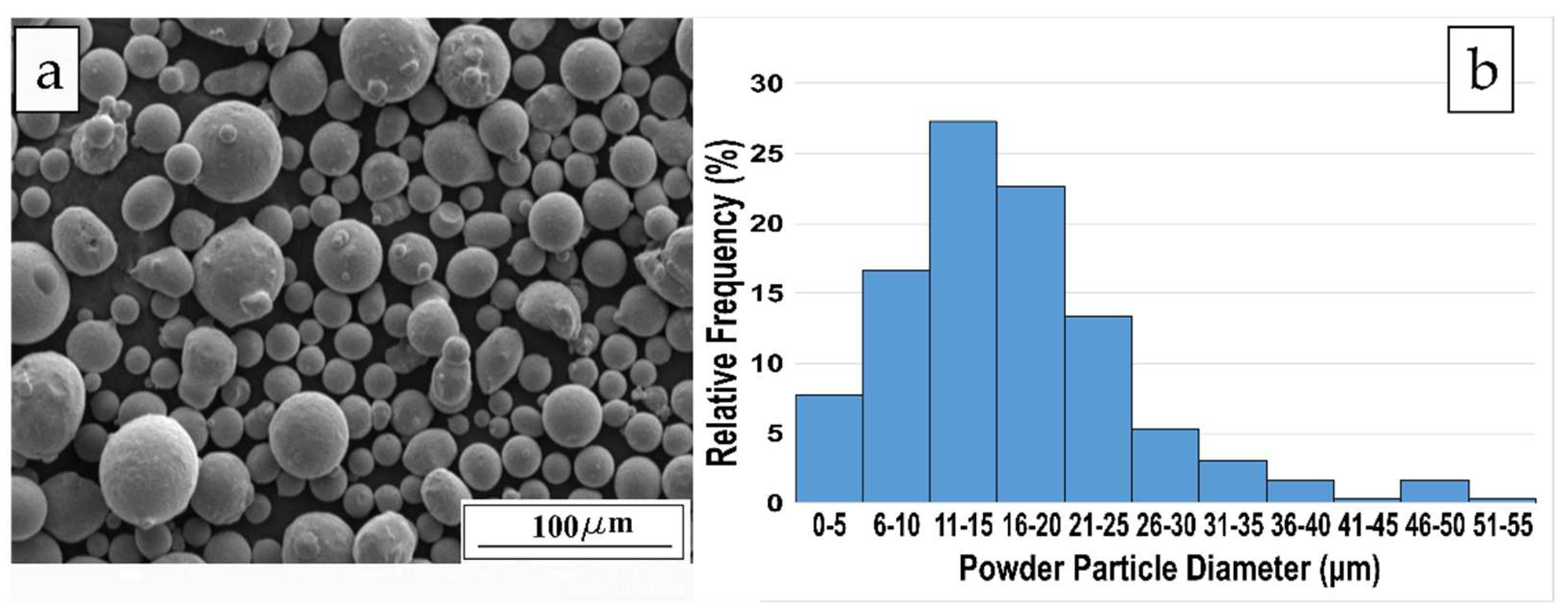
2.1. Material

Stainless steel AISI 316L powder (Chung Yo Materials. Co. Ltd., Kaohsiung City, Taiwan) was used in this study. The powder was dried at 200 °C for an hour and then slowly cooled in the furnace before it was poured into the powder tank for feeding on the SLM system. Figure 1 shows the morphology of the SS316L powder captured from a Field Emission Scanning Electron Microscope (FESEM JSM 7610F, Tokyo, Japan) and the particle size distribution analyzed by Image J software. The 316L powder dominantly shows a spherical shape, commonly fabricated by the gas atomizing process. A small amount of the fine powder was fused with the coarse powder. The particle size was in the range of 2.7–51.2 μm and the average size was 16 μm.

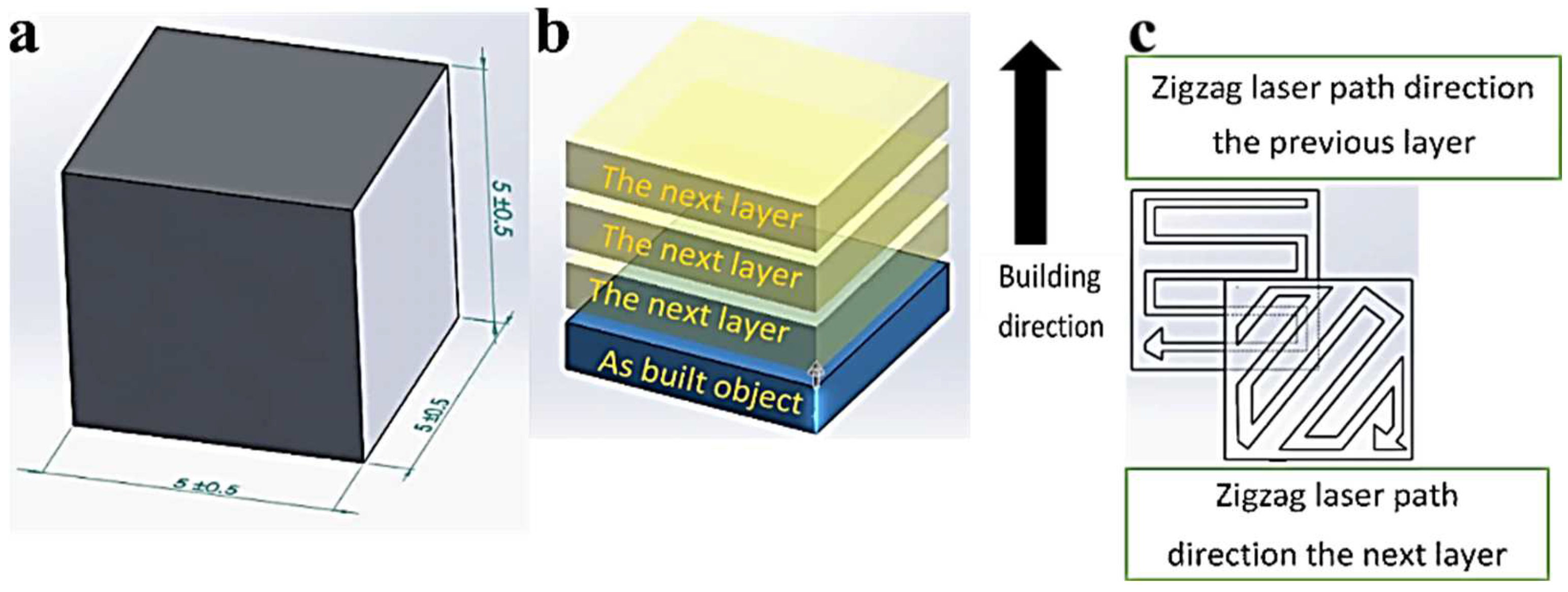
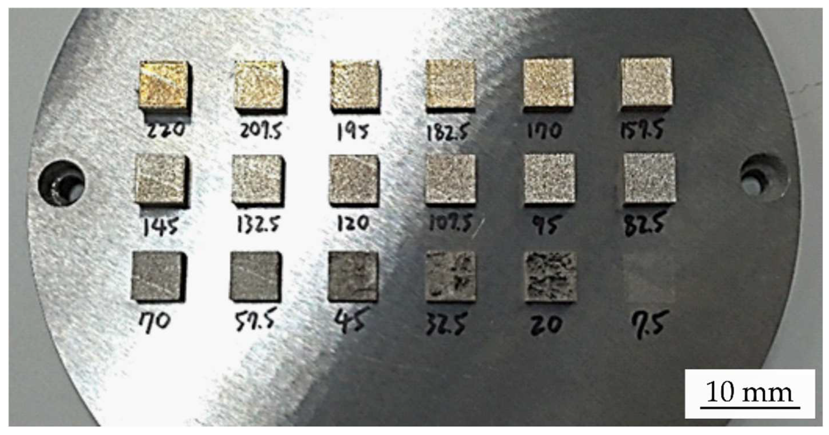
2.2. Optimization of Laser Energy Density

The cubes with the dimensions of 5 × 5 × 5 mm3 as exhibited in Figure 2a were fabricated by the SLM machine AMP-160 Tongtai (Taiwan) with a scanning speed of 700 mm/s, layer thickness of 30 μm, hatch spacing of 88 μm, and various laser powers. The employed laser powers were in the range of 7.5 W to 220 W with an increment power of 12.5 W as the variable. Meanwhile, the used laser power variables were 7.5 W, 20 W, 32.5 W, 45 W, 57.5 W, 70 W, 82.5 W, 95 W, 107.5 W, 120 W, 132.5 W, 145 W, 157.5 W, 170 W, 182.5 W, 195 W, 207.5 W, and 220 W. These parameters provided volumetric laser energy densities of 4.1 J/mm3, 10.8 J/mm3, 17.6 J/mm3, 24.4 J/mm3, 31.1 J/mm3, 37.9 J/mm3, 44.6 J/mm3, 51.4 J/mm3, 58.2 J/mm3, 64.9 J/mm3, 71.7 J/mm3, 78.5 J/mm3, 85.2 J/mm3, 91.9 J/mm3, 98.8 J/mm3, 105.5 J/mm3, 112.3 J/mm3, and 119.1 J/mm3, respectively. The building’s sliced cube layers and building direction are shown in Figure 2b. The laser scanning strategy was a combination zigzag in a strip path and the layer-by-layer fabrication was scanned by changing the angle for each incremental layer, rotated 67.5° as shown in Figure 2c. The atmosphere of the built chamber was maintained in low vacuum conditions with the oxygen concentration less than 10,000 ppm. The complete SLMed specimens were separated from the platform by the wire-electrical discharge machining (W-EDM) process.

2.3. Testing of Laser Parameter Processing Performances

The effect of laser energy density was investigated by Vickers hardness according to ASTM E92 and the porosity measurements. Each laser variable was performed for three indentation points to obtain the average value. The fabricated cubic specimens were mounted in cured epoxy and then grinded by SiC sandpaper from grade 80 to 2000. After that, the grinded specimens were polished with Al2O3 paste. The polished specimens were then measured and the hardness tested by a hardness tester (Shimadzu HMVG, Shimadzu Co. Ltd., Tokyo, Japan) with 1 kgf loading and 15 s of dwell time.
The percentages of porosity were measured by capturing the surface of polished specimens with an optical microscope machine (Whited MW 100, Huaide Industrial. Co. Ltd., Taiwan). Each specimen was observed at the same magnification at three observation points. The captured images were analyzed using image analysis software (Image J version 1.52n, NIH and LOCI, USA). The software calculated the porosity and solid area based on the clear distinction between the dark and bright areas. The value of percentage porosity was taken from the average value of the three repeated captured images for each specimen. The relative densities were calculated using the method introduced by Shi et al., and the calculated density values, ρ cal (g/cm3), were the calculated relative density multiplied with 8 g/cm3 as the theoretical bulk density, ρ theory (g/cm3), of 316L mentioned by Jiang et al. and Shi et al. [9,13]. Equations (2) and (3) were used to obtain the calculated density values, as follows:
ρ c a l = ρ c a l r e l × ρ t h e o r y
ρ c a l r e l = ( 1 A l a c k A t o t a l ) × 100 %
where Alack is the counted porosity area, Atotal is the total area of captured micro-graph, and ρ cal-rel (%) is the calculated relative density. The relative equation calculated the solid area from the captured micro-graphs.

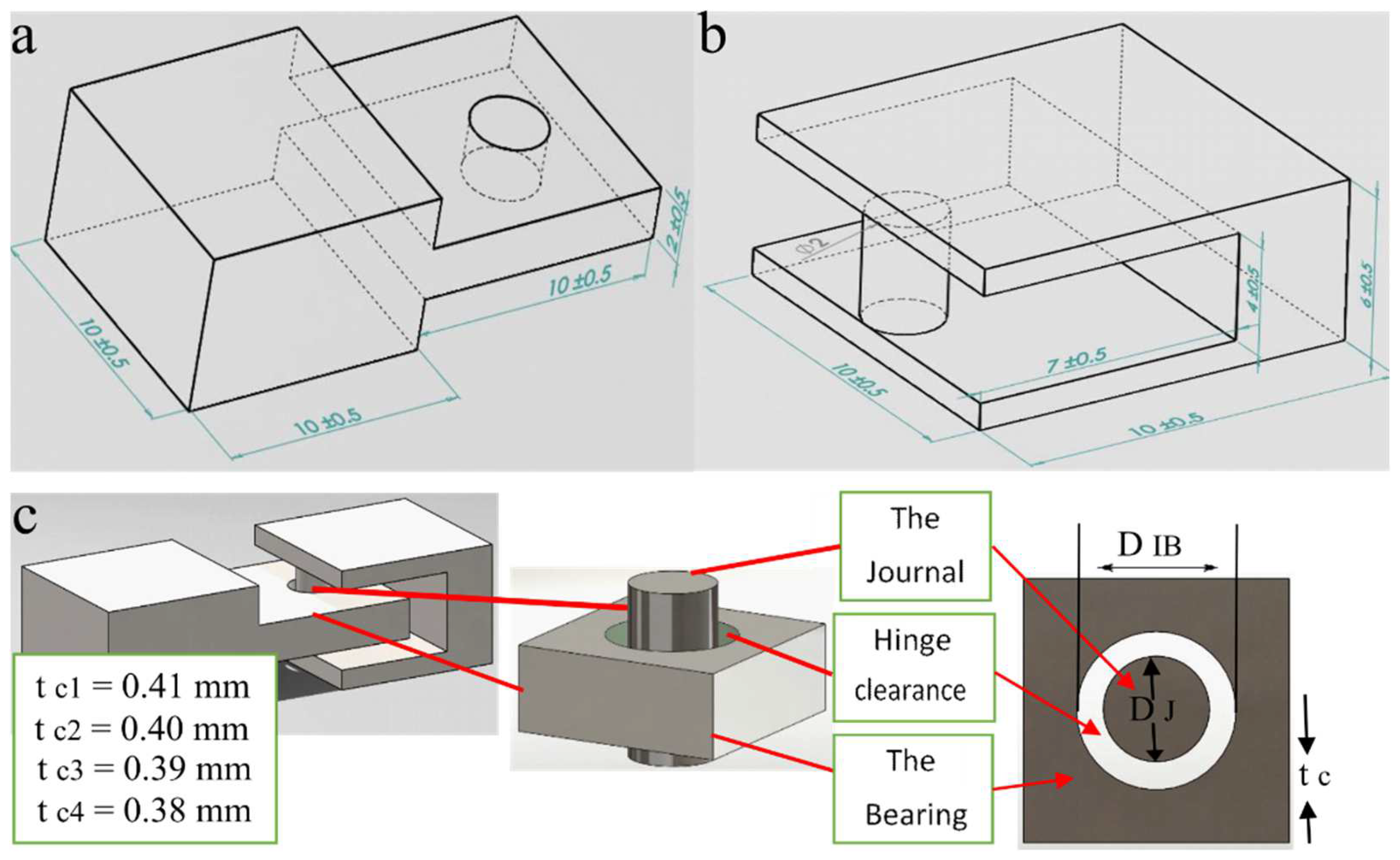
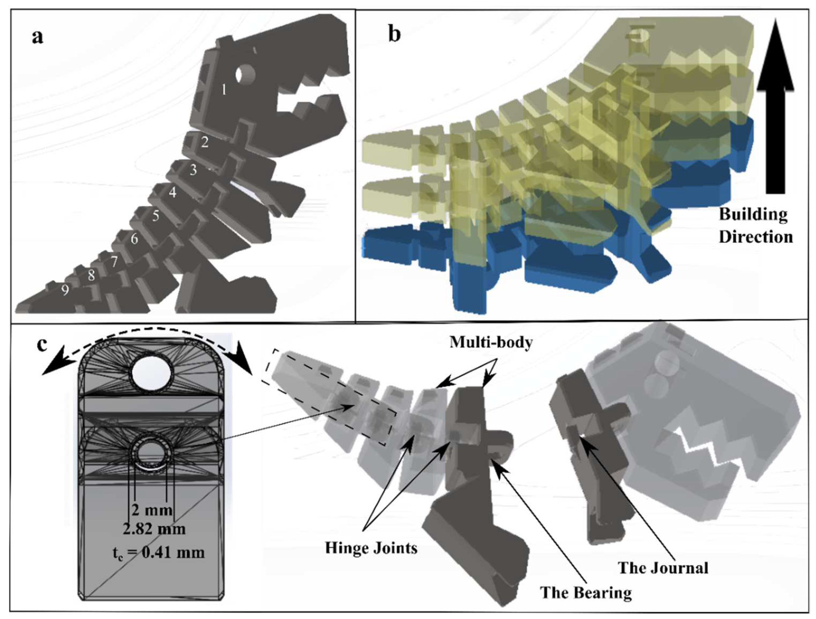
2.4. Design of Hinges

The design of the hinge is shown in Figure 3. Both the peripheral hole and the pin were integrated to the bearing house and the journal house as shown in Figure 3a,b. The hinges consisted of a cylindrical journal with a diameter of 2 mm and a peripheral hole with inner diameters of 2.82 mm, 2.8 mm, 2.78, and 2.76 mm, which were designed to provide various clearance thicknesses as shown in Figure 3c. The clearance thickness value was calculated using Equation (4), as follows:
t c = ( D I B D J ) 2
where, tc (mm) denotes the clearance thickness, DIB (mm) is the peripheral inner bearing diameter, and DJ (mm) is the journal diameter. Therefore, the designed clearance thickness values were 0.41 mm, 0.4 mm, 0.39 mm, and 0.38 mm, respectively.

2.5. SLM Process for the Hinge and Test

The SLM machine (AMP-160, Tongtai Co., Taiwan) was employed to fabricate the designed hinges with three laser parameters. The selected laser power parameters were based on two considerations, involving less porosity and the highest hardness values among the cubic specimens. In this study, the selected laser power parameters were 195 W, 207.5 W, and 220 W. Other parameters including the scanning speed, layer thickness, hatch spacing, scanning strategy, and atmosphere condition were adopted according to the previous study [9]. The positioning and layer-by-layer building direction of the hinges are shown in Figure 4. The W-EDM separated the fabricated hinges from the platform. The clearance performance was investigated by bending the hinges, since the surface of the SLMed hinges affected the movement ability. In addition, a scanning electronic microscopy (FESEM JSM 7610F, Tokyo, Japan) was employed to exhibit the surface morphology of the hinges.

2.6. Case Implementation of Free-Assembled Hinges in Dinosaur Model

Figure 5 exhibits the design of free-assembled hinges implemented in a dinosaur model. The CAD model was adopted with some design modifications. This dinosaur model consisted of a head, four body parts, and four tail parts, as shown in Figure 5a. Figure 5b shows the slicing position and building direction for the SLM process. The CAD model was fabricated in the side-lying position. The model was fabricated without any support structure. The optimized volumetric laser energy density was selected to fabricate the CAD model. Figure 5c shows the detail of the hinge joint configuration. Eight hinges, consisting of the journal with a diameter of 2 mm and the inner bearing diameter of 2.82 mm, were used to join nine segments of the multi-body. The fabricated model was expected to perform flexure movement, as shown in Figure 5.

3. Results and Discussion

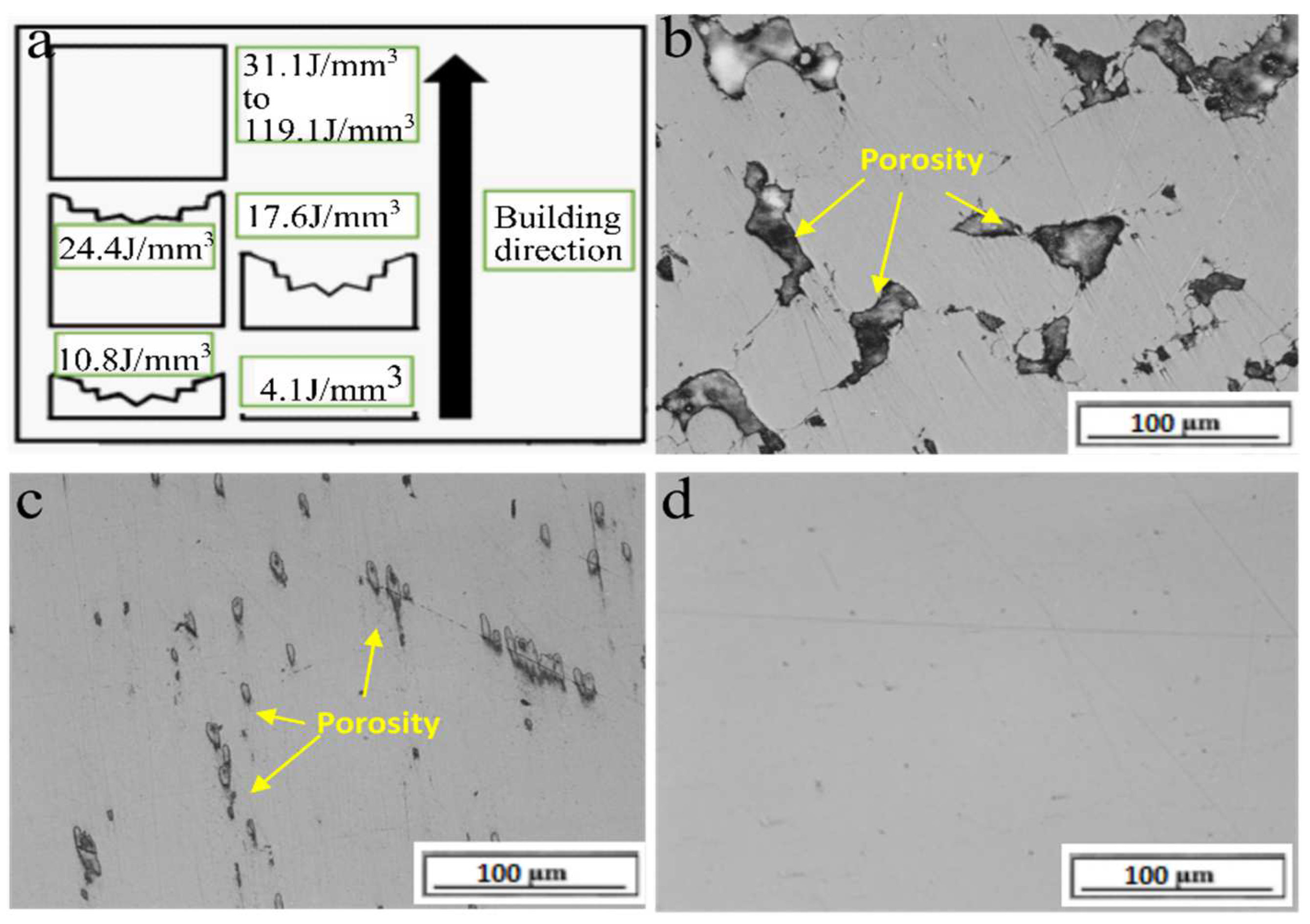
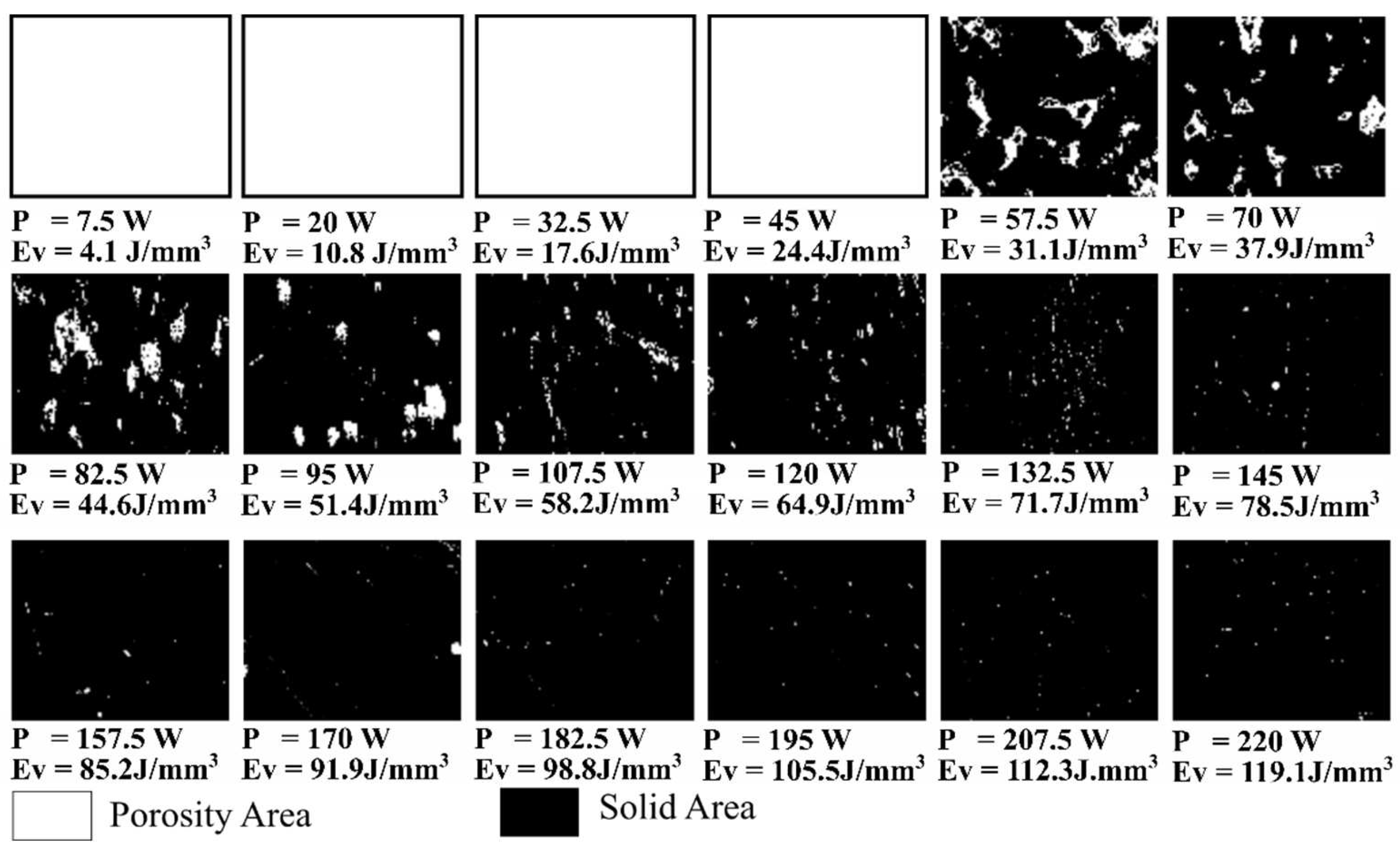
3.1. The Effect of Laser Energy Density on Porosity of Fabricated Specimens

Figure 6 shows the fabricated specimens. The combination of different laser powers from 7.5 W to 220 W with the scanning speed of 700 mm/s, layer thickness of 30 μm, and hatch spacing of 88 μm provide different input laser energy ranging from 4.1 J/mm3 to 119.1 J/mm3. The laser power of 7.5 W, provided the volumetric laser energy density of 4.1 J/mm3, could not fuse the deposited 316L powder on the substrate because this laser power promoted insufficient energy for melting the powder. The powder could be melted by laser power more than 20 W or a laser energy density of more than 10.8 J/mm3. However, the 20 W to 45 W laser power with the laser energy densities of 10.8 J/mm3 to 24.4 J/mm3 could not successfully fabricate the completed the 3D objects. The cube specimens were fabricated successfully using 57.5 W to 220 W laser power that was conducted to the volumetric laser energy densities of 31.1 J/mm3 to 119.1 J/mm3.
The porosity of fabricated specimens is exhibited in Figure 7. Some laser powers, 7.5 to 45 W, emitted the laser energy of 4.1 to 24.4 J/mm3, which is considered insufficient laser energy for fabricating 3D objects, as shown in Figure 7a. The laser power of 57.5 W resulted in a 3D object with 14.61% porosity, as shown in Figure 7b. This porosity can be mentioned as a defect that causes the low mechanical properties of SLM products. The enhancement of laser power reduced the percentages of porosity, as confirmed in Figure 7c with 3.81% porosity and Figure 7d with 0.2% porosity. Table 1 and Figure 8 show the distribution and measurement results of porosity analyzed using the Image J software. The porosity is shown by the bright area, while the solid 316L is shown by the dark area. According to this table, the enhancement of laser power increased the laser energy density and decreased the porosity percentages of specimens.
Figure 9 demonstrates the scheme of porosity formation in each hatch space and the inter-layers. The emitted laser energy, controlled by the laser power, laser beam diameter, layer thickness, and hatch space, was expected to provide input energy that can produce an overlap configuration of the melt pool. This laser energy interacts with the deposited powder particle and the underneath layer. This energy may be reflected, scattered, and absorbed during this interaction. The absorbed laser energy transforms into heat energy, which melts the 316L powder and re-melts the underneath layer. The molten 316L forms a spot in the melt pool. After that, the solidification of the melt pool occurs because of the cooling. The laser energy density moved in the zig-zag path causes the next melt pool beside the solidified alloy to appear. This movement partially re-melts the previously solidified alloy and the underneath layer [14]. This build mechanism is repeated until the object is completely fabricated. The defect-free results were formed when the overlap zone filled the inter-hatches and interlayers gap. The overlap zone produces an interconnected melt spot among the inter-hatches and interlayers. The combination of laser power, scanning speed, beam diameter, layer thickness, and hatch space on the spot generated energy distribution with specific diameter and depth as described by Chen et al. and Liu et al. [15,16]. Extra-low laser energy density values, ranging from 4.1 J/mm3 to 24.4 J/mm3, fail to generate the interconnected melt of the 316L. Insufficient laser energy density in the range of 57 J/mm3 to 64.9 J/mm3 leads to bad overlap melt, poor interconnected bonding, and more than 1% porosity. The laser energy density in the range of 71.7 J/mm3 to 119.1 J/mm3 resulted in 3D objects with 99% densification and less than 1% defect. Yakout et al. [17,18] determined the term of the critical laser energy density as the value of 104 J/mm3. This critical energy density corresponds to proper setting parameters for minimizing the defects of SLM products. The excessive volumetric energy density of more than 156.3 J/mm3 causes vaporization, delamination, cracks, keyholes, and spatters. In the porosity observation, the highest energy density was less than 156 J/mm3 so that some defects such as delamination, keyholes, and cracks could be avoided.

3.2. The Effect of Laser Power and Energy Density on Hardness in Fabricated Specimens

The average hardness of the cube specimens SLMed using various laser parameters and their relation with the percentages of porosity are shown in Figure 10 and Figure 11. The lowest hardness, in the value of 128 HV, is exhibited with the specimens fabricated using the laser powers of 57.5 W and 70 W, or the cubes SLMed using volumetric laser energy densities of 31.1 J/mm3 and 37.9 J/mm3. The hardness value increases significantly by applying the laser power and laser energy density of 82.5 W and 44.6 J/mm3. Enhancing the laser power and laser energy density to 220 W and 119.1 J/mm3 raises the hardness values. The highest hardness value of 215 HV was generated by implementing the laser power of 220 W and laser energy density of 119.1 J/mm3. Figure 10 and Figure 11 also show the relationship between the percentage porosity and hardness property. The higher volumetric laser energy density reduces the percentages of porosity and promotes higher densification and hardness of SLMed 316L. The porosity within the SLMed 316L increases the collapse potential of the solid object under load during the hardness test. Shi et al. [13] said the densification, defect, microstructure, and residual stress of SLMed results influence the mechanical properties. The laser energy is higher than the critical laser energy will increase the densification, reduces the percentages of porosity defect, enhances the residual stress, and improves mechanical properties. Table 1 shows the relationship between the calculated relative density and the hardness properties of specimens.
The three optimized laser parameters were selected according to the highest density, lowest porosity, and proper hardness values. Luo et al. [19] mentioned that 316L fabricated using the casting method has a hardness of 200 HV. Tayyab et al. [20] said the hardness of cold-rolled 316L is 285 HV, and annealed 316L is 147 HV. The average hardness of the 316L fabricated by casting, rolling, and annealing is 210 HV. Regarding these references, the selected laser parameters for hinge fabrications were the volumetric laser energy densities of 105.5 J/mm3, 112.3 J/mm3, and 119.1 J/mm3 since they resulted in a relative density higher than 99.75% and hardness around 210 HV.

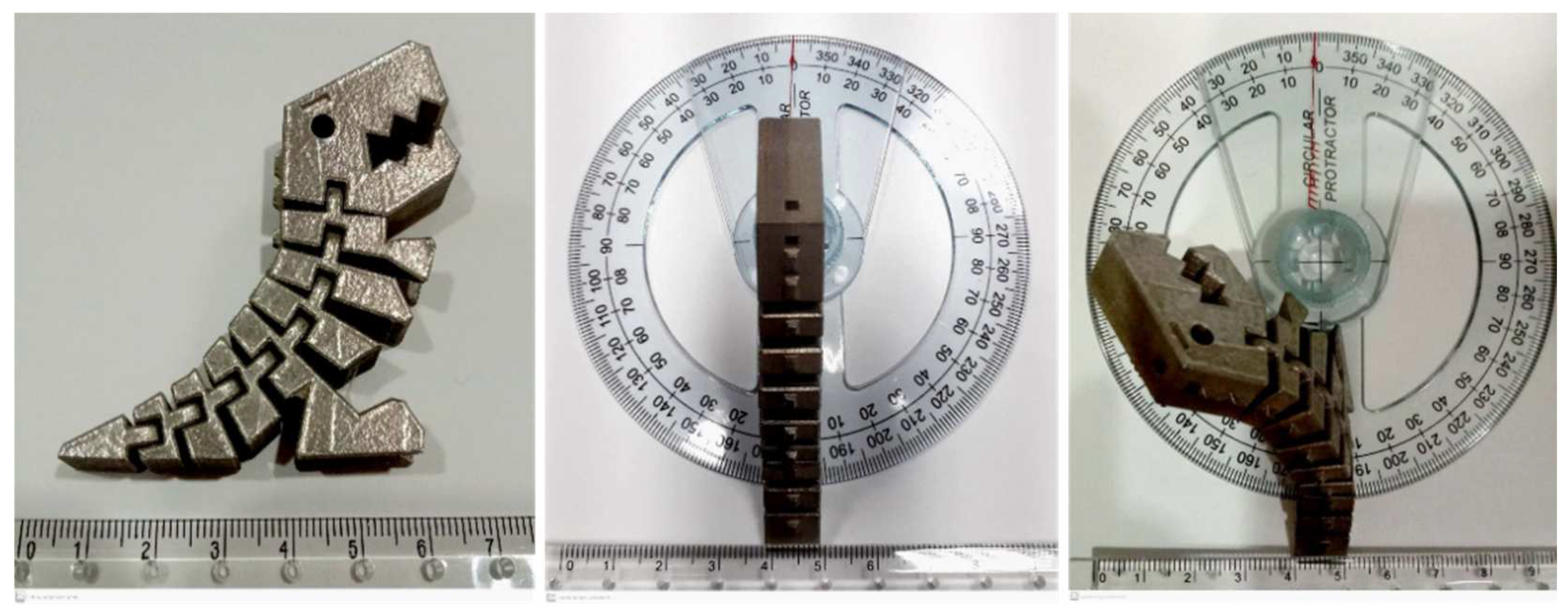
3.3. The Fabricated Hinges

The 316L hinges were successfully fabricated using the volumetric laser energy densities of 105.5 J/mm3, 112.3 J/mm3, and 119.1 J/mm3. These laser energy values were obtained by controlling the scanning speed of 700 mm/s, the hatch space of 88 μm, the layer thickness of 30 μm, and the laser power of 195 W, 207.5 W, and 220 W. The clearances between the journal and the bearing were designed as 0.41 mm, 0.40 mm, 0.39 mm, and 0.38 mm. This study aims to find the minimum clearance to produce a movable hinge using the three optimized SLM parameters. Figure 12 exhibits the table for the movement ability of SLMed hinges with various fabrication parameters and clearance designs. The 105.5 J/mm3 laser energy implementation resulted in movable hinges with four clearance sizes. The laser energy density of 112.3 J/mm3 generated movable hinges with a clearance size above 0.39 mm. In comparison, the 0.38 mm clearance was unmovable. The increase in laser energy density to 119.1 J/mm3 reduces the hinges’ movement ability. The application of selected volumetric laser energy densities successfully fabricated movable hinges with a minimum clearance size of 0.41 mm.
The movement ability of hinges was affected by the design and SLM processing parameters. The clearances that resulted from SLM are different from the design. The fabricated parts had a smaller clearance than the designed parts. Liu et al. [21] employed the laser energy density of 156 J/mm3 in clearance with the design of 0.35 mm and 0.4 mm. The results showed that the actual clearance from SLM was 0.245 mm and 0.288 mm. The laser parameters affect the surface roughness and geometrical accuracy of SLMed products. Figure 13 shows the surface morphology for the top and side surface of SLMed 316L. The higher laser energy density resulted in a smoother surface on the top views, as shown in Figure 13a,b. Seung et al. [22] said that increasing the laser power corresponding to the enhancement of laser energy reduces the roughness number (Ra) for the top surface. However, due to the staircase phenomenon, the higher laser energy density resulted in a rougher side surface, as shown in Figure 13c,d. Bahshwan et al. [23] observed the tribological performance of SLMed 316L. The result showed the different micro-geometry on the top and side surface caused anisotropic friction. The staircase effect is more apparent on the side surface of the part fabricated using the higher laser energy density. The staircase effect appears because the untargeted powder was sintered to the side surface, resulting in higher surface roughness. Kuo et al. [24] mentioned that the enhancement of laser power increases dimension in the X, Y, and Z directions. The components of fabricated hinges included the journal, and the bearing had bigger dimensions than their designs that promoted smaller clearance. The increase in laser power led to the reduction in the clearance, raised the surface roughness, and caused disturbance for the movement of the hinges.

3.4. Case Implementation

Figure 14 shows the dinosaur model successfully fabricated by SLM. The model was designed with a multibody. Each body was joined with the universal hinges, as exhibited in Figure 4. The description of universal hinges and other types of hinges has been explained by Lussenburg et al. [25]. The multibody model consisted of nine segmented units and was completed with a front bearing house and a back journal for each segment. The segmented bodies were joined with eight hinges. The hinge joints implemented the clearance of 0.41 mm, and Table 2 shows the setting of SLM parameters. The hinge mechanism worked properly and allowed the multibody to be bent.

4. Conclusions

The 316L components were fabricated using SLM. In the process with the variables of volumetric laser energy density and joint clearance optimization, the following major conclusions were obtained from this work:
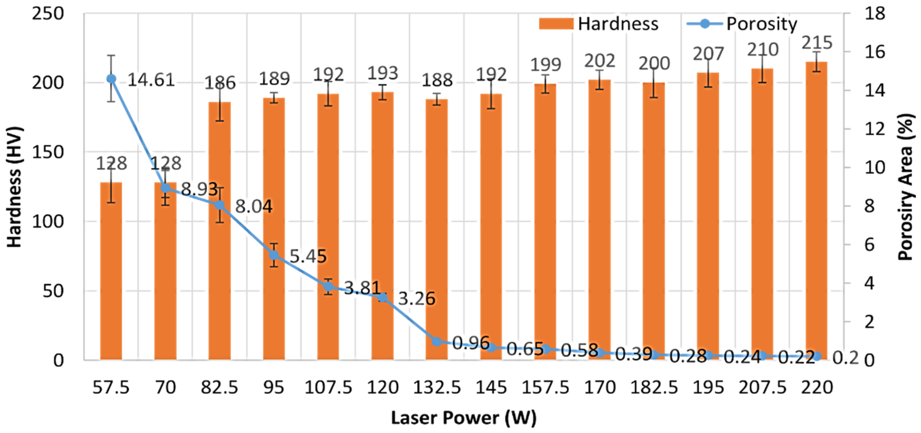
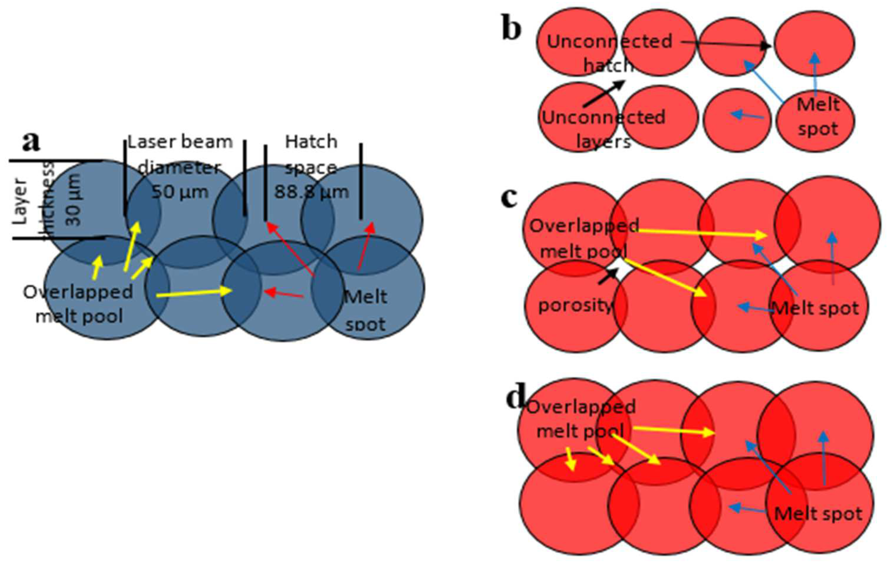
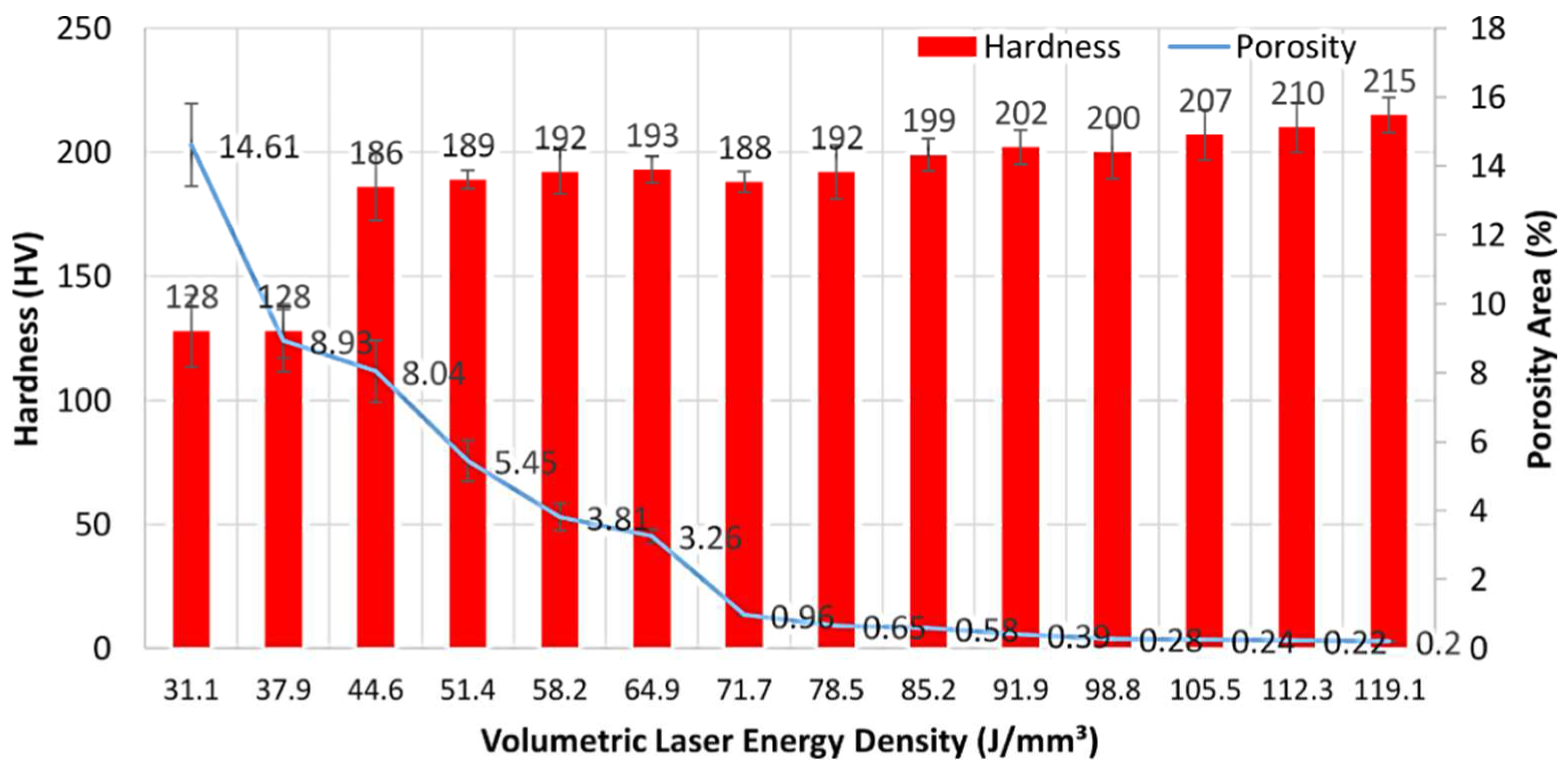
  • The enhancement of volumetric laser energy density ranging from 31.1 J/mm3 to 119.1 J/mm3, controlled by increasing the laser power from 57.5 W to 220 W with the constant scanning speed of 700 mm/s, layer thickness of 30 μm, and hatch space of 88.8 μm, results in the decrease in the porosity and increase in the densification of 316L. The volumetric laser energy densities from 71.7 J/mm3 to 119.1 J/mm3 generated the 3D 316L object with less than 1% porosity and densification of more than 99%.
  • The reduction in porosity increases the hardness properties. The laser energy densities of 105.5 J/mm3, 112.3 J/mm3, and 119.1 J/mm3 are considered as the optimized laser power parameters since they produce 316L with a hardness value close to 210 HV. This hardness value is similar to the average hardness of 316L that is manufactured using other pre-existing methods.
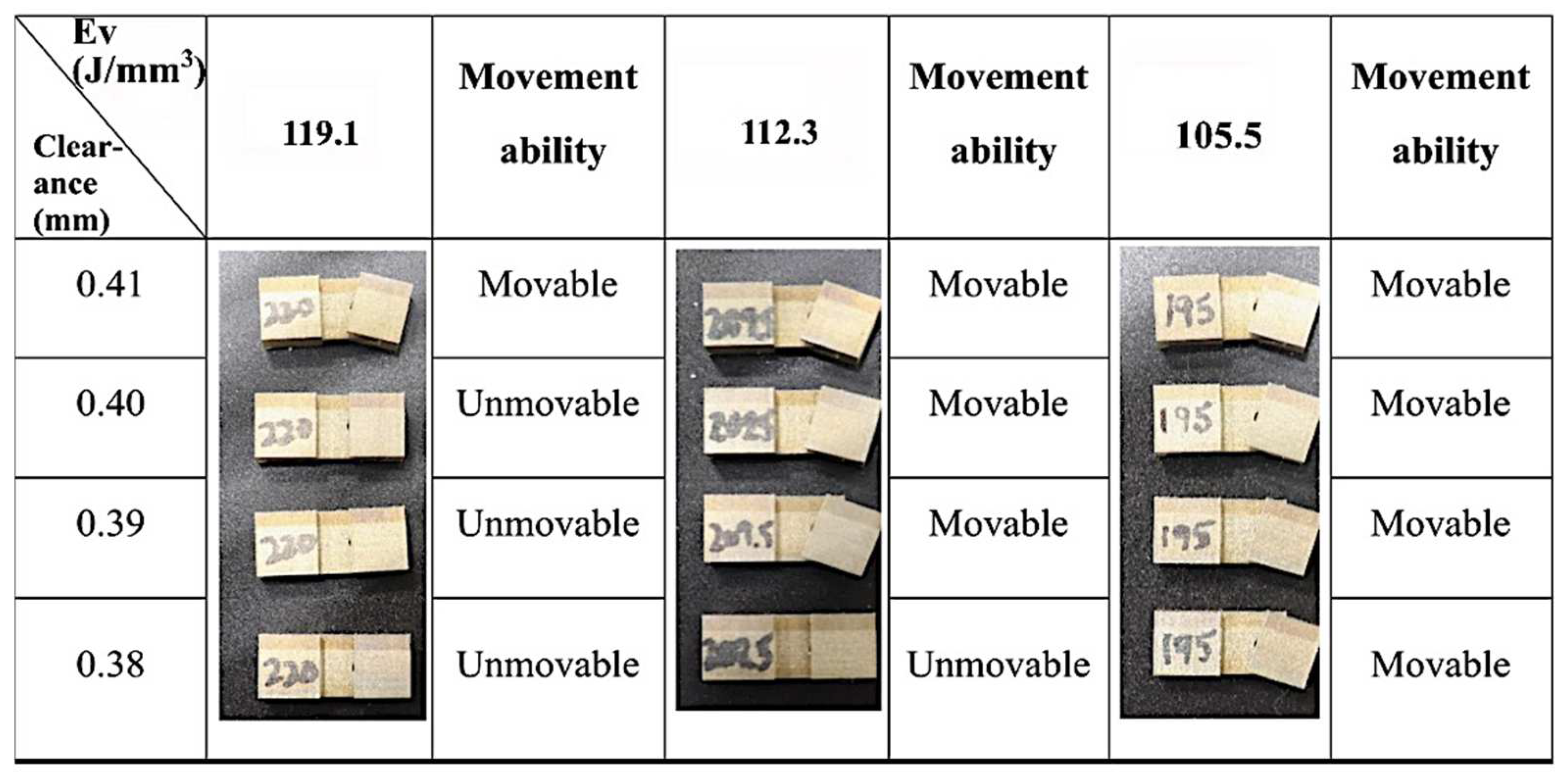
  • The minimum clearance design for hinge joints that can be fabricated using the optimized laser parameters in this work is 0.41 mm. The enhancement of laser power leads to restrictions in the hinges’ movement ability.

Author Contributions

Conceptualization, C.-P.J. and A.T.W.; methodology C.-P.J. and S.-H.W.; software, S.-H.W.; validation, C.-P.J., A.T.W., and S.-H.W.; formal analysis, A.T.W.; investigation, S.-H.W.; resources, C.-P.J.; data curation, A.T.W. and M.R.; writing—original draft preparation, A.T.W., M.R., and T.P.; writing—review and editing, C.-P.J. and A.T.W.; visualization, A.T.W.; supervision, C.-P.J.; project administration, C.-P.J.; funding acquisition, C.-P.J. and M.R. All authors have read and agreed to the published version of the manuscript.

Funding

The authors are grateful for the financial support of the Ministry of Science and Technology (MOST), Taiwan, under Grant No. 110-2622-E-027-026 and 110-2218-E-A49A-502.

Institutional Review Board Statement

Not applicable.

Informed Consent Statement

Not applicable.

Data Availability Statement

The data presented in this study are available on request from the corresponding author.

Acknowledgments

This work is also supported by the Additive Manufacturing Center for Mass Customization Production of the Featured Area Research Center Program within the framework of the Higher Education Sprout Project of the Taiwan Ministry of Education (MOE).

Conflicts of Interest

The authors declare no conflict of interest.

References

  1. Calì, J.; Calian, D.A.; Amati, C.; Kleinberger, R.; Steed, A.; Kautz, J.; Weyrich, T. 3d-printing of non-assembly, articulated models. ACM Trans. Graph. 2012, 31, 1–8. [Google Scholar] [CrossRef]
  2. De Laurentis, K.J.; Mavroidis, C. Rapid fabrication of a non-assembly robotic hand with embedded components. Assem. Autom. 2004, 24, 394–405. [Google Scholar] [CrossRef]
  3. Seneci, C.A.; Shang, J.; Darzi, A.; Yang, G.Z. Rapid manufacturing with selective laser melting for robotic surgical tools: Design and process considerations. In Proceedings of the 2015 IEEE/RSJ International Conference on Intelligent Robots and Systems (IROS), Hamburg, Germany, 28 September–2 October 2015; pp. 824–830. [Google Scholar] [CrossRef]
  4. Chen, Y.; Lu, J. Minimize joint clearance in rapid fabrication of non-assembly mechanisms. Int. J. Comput. 2011, 24, 726–734. [Google Scholar] [CrossRef]
  5. Su, X.; Yang, Y.; Wang, D.; Chen, Y. Digital assembly and direct fabrication of mechanism based on selective laser melting. Rapid Prototyp. J. 2013, 19, 166–172. [Google Scholar] [CrossRef]
  6. Sivaraj, D.; Vijayalakshmi, K. Novel synthesis of bioactive hydroxyapatite/f-multiwalled carbon nanotube composite coating on 316L SS implant for substantial corrosion resistance and antibacterial activity. J. Alloys Compd. 2019, 777, 1340–1346. [Google Scholar] [CrossRef]
  7. Eliasu, A.; Czekanski, A.; Boakye, Y.S. Effect of laser powder bed fusion parameters on the microstructural evolution and hardness of 316l stainless steel. Int. J. Adv. Manuf. 2021, 113, 2651–2669. [Google Scholar] [CrossRef]
  8. Greco, S.; Gutzeit, K.; Hotz, H.; Kirsch, B.; Aurich, J.C. Selective laser melting (slm) of aisi 316L|impact of laser power, layer thickness, and hatch spacing on roughness, density, and microhardness at constant input energy density. Int. J. Adv. Manuf. 2020, 108, 1551–1562. [Google Scholar] [CrossRef]
  9. Jiang, C.-P.; Wibisono, A.T.; Pasang, T. Selective laser melting of stainless steel 316l with face-centered-cubic-based lattice structures to produce rib implants. Materials 2021, 14, 5962. [Google Scholar] [CrossRef]
  10. Rottger, A.; Boes, J.; Theisen, W.; Thiele, M.; Esen, C.; Edelmann, A.; Hellmann, R. Microstructure and mechanical properties of 316L austenitic stainless steel processed by different SLM devices. Int. J. Adv. Manuf. 2020, 108, 769–783. [Google Scholar] [CrossRef]
  11. Boschetto, A.; Bottini, L. Manufacturability of non-assembly joints fabricated in AlSi10Mg by selective laser melting. J. Manuf. Process. 2019, 37, 425–437. [Google Scholar] [CrossRef]
  12. Mugwagwa, L.; Dimitrov, D.; Matope, S.; Yadroitsev, I. Influence of process parameters on residual stress related distortions in selective laser melting. Procedia Manuf. 2018, 21, 92–99. [Google Scholar] [CrossRef]
  13. Shi, W.; Wang, P.; Liu, Y.; Hou, Y.; Han, G. Properties of 316l formed by a 400 w power laser selective laser melting with 250 mm layer thickness. Powder Technol. 2020, 360, 151–164. [Google Scholar] [CrossRef]
  14. Liu, W.; Wei, H.; Liu, A.; Zhang, Y. Multi-index co-evaluation of metal laser direct deposition: An investigation of energy input effect on energy efficiency and mechanical properties of 316L parts. J. Manuf. Process. 2022, 76, 277–290. [Google Scholar] [CrossRef]
  15. Chen, Z.; Xiang, Y.; Wei, Z.; Wei, P.; Lu, B.; Zhang, L.; Du, J. Thermal dynamic behavior during selective laser melting of k418 superalloy: Numerical simulation and experimental verification. Appl. Phys. 2018, 124, 1–16. [Google Scholar] [CrossRef]
  16. Liu, Y.; Zhang, M.; Shi, W.; Ma, Y.; Yang, J. Study on performance optimization of 316l stainless steel parts by high-efficiency selective laser melting. Opt. Laser Technol. 2021, 138, 106872. [Google Scholar] [CrossRef]
  17. Yakout, M.; Elbestawi, M.; Veldhuis, S.C. On the characterization of stainless steel 316l parts produced by selective laser melting. Int. J. Adv. Manuf. Technol. 2018, 95, 1953–1974. [Google Scholar] [CrossRef]
  18. Yakout, M.; Elbestawi, M.; Veldhuis, S.C. A study of thermal expansion coefficients and microstructure during selective laser melting of Invar 36 and stainless steel 316L. Addit. Manuf. 2018, 24, 405–418. [Google Scholar] [CrossRef]
  19. Luo, J.; Jia, X.; Gu, R.; Zhou, P.; Huang, Y.; Sun, J.; Yan, M. 316l stainless steel manufactured by selective laser melting and its biocompatibility with or without hydroxyapatite coating. Metals 2018, 8, 548. [Google Scholar] [CrossRef] [Green Version]
  20. Tayyab, K.B.; Farooq, A.; Alvi, A.A.; Nadeem, A.B.; Deen, K. Corrosion behavior of cold-rolled and post heat-treated 316L stainless steel in 0.9 wt% NaCl solution. Int. J. Miner. Metall. Mater. 2021, 28, 440–449. [Google Scholar] [CrossRef]
  21. Liu, Y.; Zhang, J.; Yang, Y.; Li, J.; Chen, J. Study on the influence of process parameters on the clearance feature in non-assembly mechanism manufactured by selective laser melting. J. Manuf. Processes. 2017, 27, 98–107. [Google Scholar] [CrossRef]
  22. Seung, Y.C.; Gwang, Y.S.; Do, S.K. Effect of laser remelting on the surface characteristics of 316L stainless steel fabricated via direct energy deposition. J. Mater. Ses. Technol. 2021, 15, 5814–5832. [Google Scholar] [CrossRef]
  23. Bahshwan, M.; Gee, M.; Nunn, J.; Myant, C.W.; Reddyhoff, T. In situ observation of anisotropic tribological contact evolution in 316l steel formed by selective laser melting. Wear 2022, 490, 204193. [Google Scholar] [CrossRef]
  24. Kuo, C.; Chen, Y.; Nien, Y. Effects of energy parameters on dimensional accuracy when joining stainless-steel powders with heterogeneous metal substrates. Materials 2021, 14, 320. [Google Scholar] [CrossRef] [PubMed]
  25. Lussenburg, K.; Sakes, A.; Breedveld, P. Design of non-assembly mechanism: A state–of–the-art review. Addit. Manuf. 2021, 39, 101846. [Google Scholar] [CrossRef]
Figure 1. Micrograph of SS316L powder: (a) morphology of the powder captured by SEM, and (b) powder size distribution analysis.
Metals 12 01223 g001
Figure 2. Design specimen for laser energy optimization: (a) visual 3D cube dimensions, (b) building direction layer by layer, and (c) zigzag scan strategy with the angle of the laser path changing for each incremental layer.
Metals 12 01223 g002
Figure 3. Design of the hinge detail components: (a) housing of the bearing, (b) housing of the journal, and (c) configuration of the bearing peripheral hole, journal, and clearance.
Metals 12 01223 g003
Figure 4. Building position of hinges.
Metals 12 01223 g004
Figure 5. Design of free-assembled hinges in model of a dinosaur. (a) The number of each segment, (b) Demonstration of building direction and (c) the clearance and dimension of hinge joint of multi-body.
Metals 12 01223 g005
Figure 6. Fabricated cube specimens with various laser power and laser volumetric energy density.
Metals 12 01223 g006
Figure 7. Fabricated specimens: (a) scheme of fabricated specimen’s side views, (b) micrograph of specimen fabricated by laser power of 57.5 W (Ev = 31.1 J/mm3), (c) 107.5 W (Ev = 58.2 J/mm3), and (d) 220 W (Ev = 119.1 J/mm3) from top view.
Metals 12 01223 g007
Figure 8. Distribution of porosity in SLMed specimens.
Metals 12 01223 g008
Figure 9. Scheme of porosity formation: (a) design of melting spot, (b) extra low laser beam result, (c) insufficient laser energy promotes a small melting spot, and (d) proper laser energy promotes a larger melting spot and more overlap melt.
Metals 12 01223 g009
Figure 10. Influence of laser power on porosity and hardness of SLMed 316L.
Metals 12 01223 g010
Figure 11. Influence of volumetric laser energy density on porosity and hardness of fabricated 316L.
Metals 12 01223 g011
Figure 12. Mapping for the movement ability of hinges SLMed using different laser power and clearance designs.
Metals 12 01223 g012
Figure 13. Surface morphology of the top hinges SLMed using (a) 105.5 J/mm3 and (b) 119.1 J/mm3 volumetric energy density, and the side hinges SLMed using (c) 105.5 J/mm3 and (d) 119.1 J/mm3 volumetric energy density.
Metals 12 01223 g013
Figure 14. Multibody model resulting from SLM and applying the journal-bearing clearance of 0.41 mm.
Metals 12 01223 g014
Table 1. The effect of laser parameters on density, porosity, and hardness properties of 316L.
P (W) Ev (J/mm3) Porosity (%) ρcal-rel (%)ρcal (g/cm3) Hardness (HV)
57.531.114.61 ± 1.285.39 ± 1.26.83 ± 0.096128 ± 14.5
7037.98.93 ± 0.991.07 ± 0.97.29 ± 0.072128 ± 10.9
82.544.68.04 ± 0.991.96 ± 0.97.36 ± 0.072186 ± 13.6
9551.45.45 ± 0.694.55 ± 0.67.56 ± 0.048189 ± 3.7
107.558.23.81 ± 0.496.19 ± 0.47.69 ± 0.032192 ± 8.8
12064.93.26 ± 0.296.74 ± 0.27.73 ± 0.016193 ± 5.4
132.571.70.96 ± 0.0199.04 ± 0.017.92 ± 0.008188 ± 4.2
14578.50.65 ± 0.0199.35 ± 0.017.94 ± 0.008182 ± 10.8
157.585.20.58 ± 0.0199.42 ± 0.017.96 ± 0.008188 ± 6.5
17091.90.39 ± 0.0199.61 ± 0.017.97 ± 0.008202 ± 6.9
182.598.80.28 ± 0.0199.72 ± 0.017.97 ± 0.008200 ± 10.8
195105.50.24 ± 0.0199.76 ± 0.017.98 ± 0.008207 ± 10.2
207.5112.30.22 ± 0.0199.78 ± 0.017.98 ± 0.008210 ± 9.8
220119.10.20 ± 0.0199.80 ± 0.017.98 ± 0.008215 ± 7.1
Table 2. SLM parameters to fabricate model.
P (W)v (mm/s)h (mm)t (mm)Ev (J/mm3)
1957000.0890.030105.5
Publisher’s Note: MDPI stays neutral with regard to jurisdictional claims in published maps and institutional affiliations.

