
A Numerical Study into the Effect of Machining on the Interaction between Surface Roughness and Surface Breaking Defects on the Durability of WAAM Ti-6Al-4V Parts

 ,
,  ,
,  ,
,
Abstract
:1. Introduction
- (i)
- Advanced manufacturing can be used to address the readiness challenges posed by parts obsolescence, diminishing sources of supply, and sustained operations in austere environments.
- (ii)
- If employed to the maximum extent, advanced manufacturing could transform battlefield logistics through on-demand fabrication of parts close to the point of need, thus reducing the large number of parts stored and transported around the world.
- (a)
- The effect of different AM processes;
- (b)
- The effect of different build directions;
- (c)
- The residual stress fields induced by the different manufacturing process;
- (d)
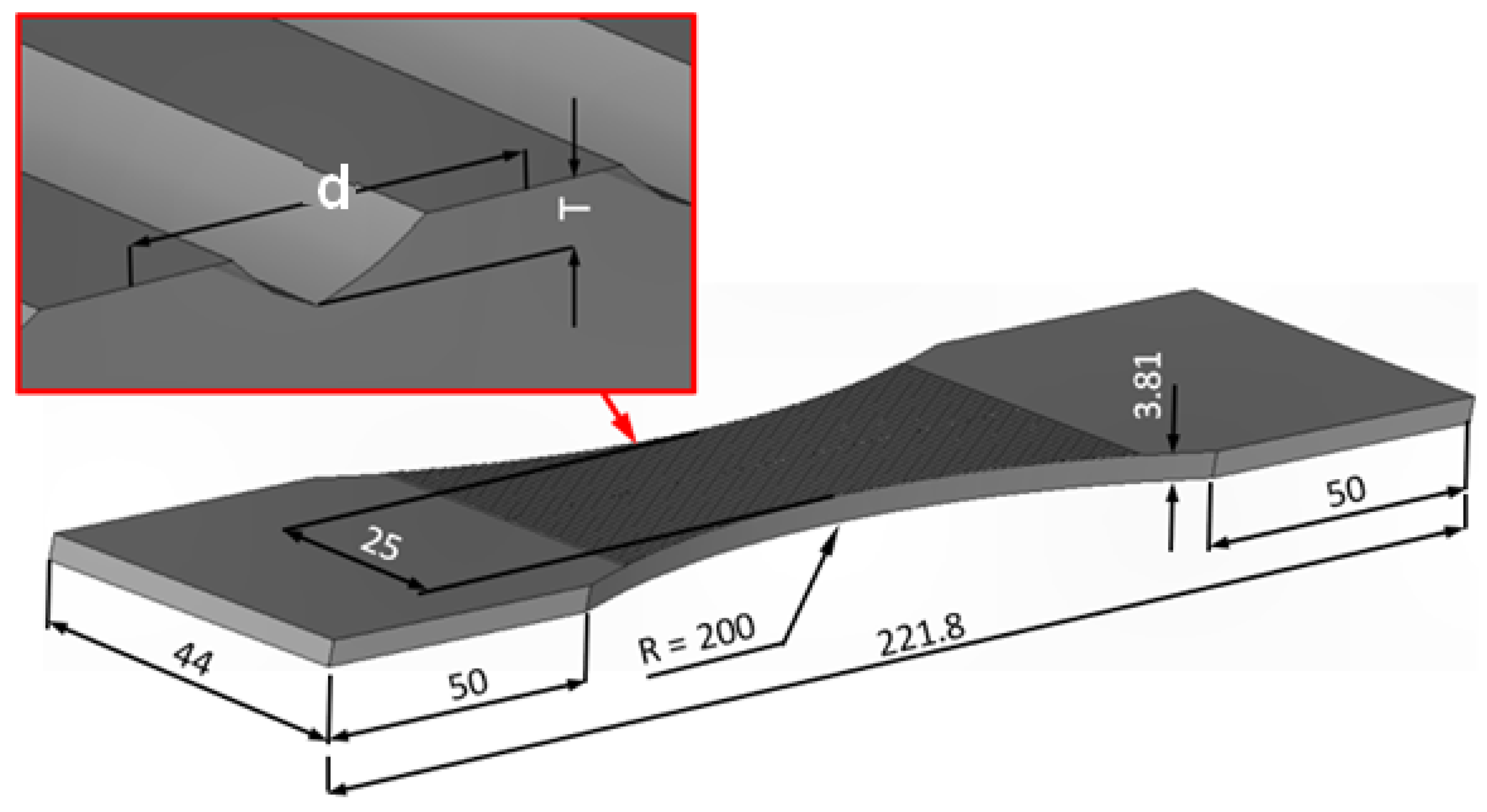
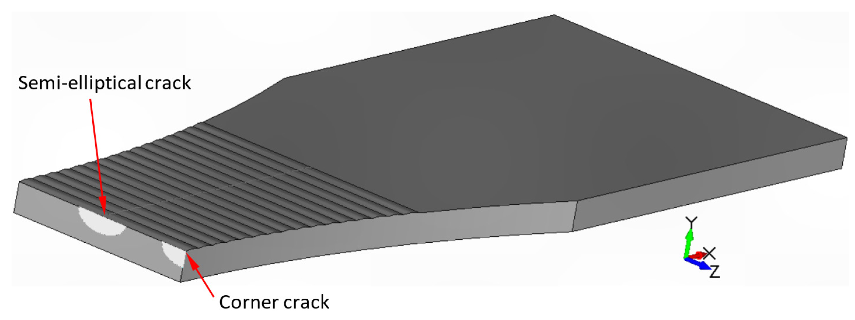
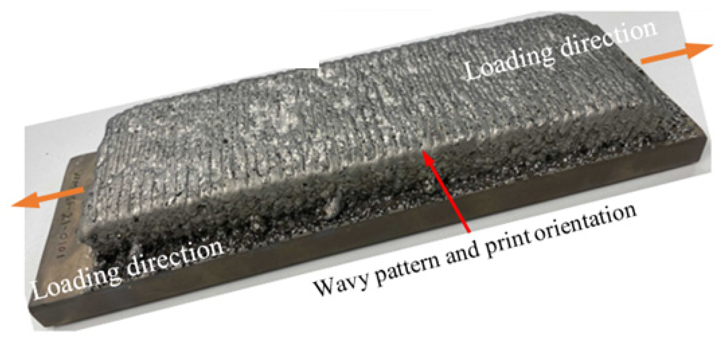
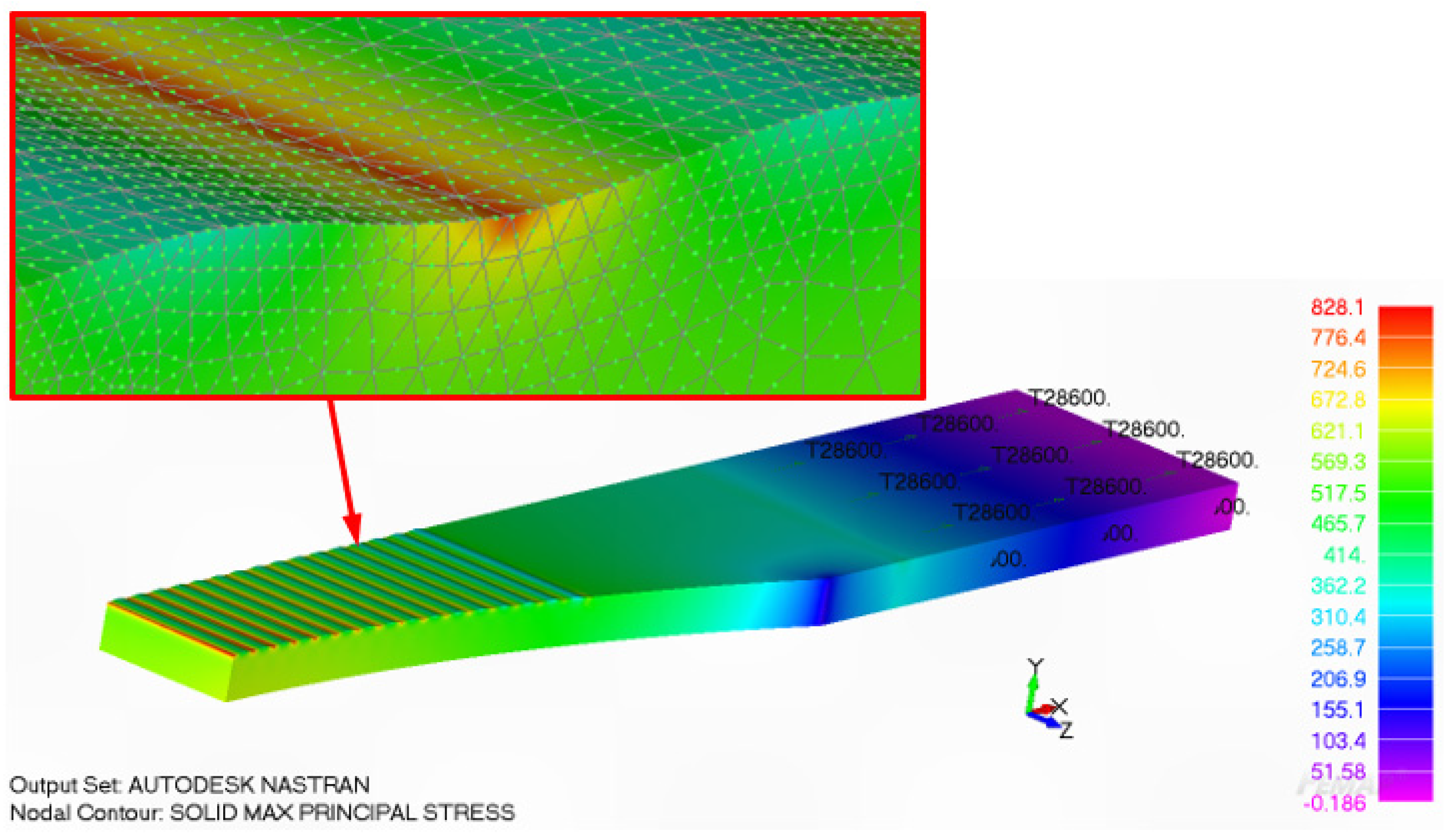
2. Materials and Methods
3. On the Interaction between Surface Roughness and Surface Breaking Defects on the Durability of WAAM Ti-6Al-4V Parts
4. Effect of Machining the Rough Surfaces
5. Conclusions
- Comparing the fatigue life-associated surfaces left in the unmachined state, the durability of an AM part appears to be a relatively strong function of the local radius of the curvature of the trough associated with the rough surfaces.
- Surfaces with tall narrow roughness exhibit the largest reductions in fatigue life and these cases do not overly benefit from partial machining of the surface.
- The size of the initial material discontinuities, porosity, lack of fusion, etc., associated with the AM process appears to strongly affect the fatigue life of the part.
Author Contributions
Funding
Institutional Review Board Statement
Informed Consent Statement
Data Availability Statement
Acknowledgments
Conflicts of Interest
References
- Under Secretary. Acquisition and Sustainment, Directive-type Memorandum (DTM)-19-006-Interim Policy and Guidance for the Use of Additive Manufacturing (AM) in Support of Materiel Sustainment, Pentagon, Washington, DC, USA. 21 March 2019. Available online: https://www.esd.whs.mil/Portals/54/Documents/DD/issuances/dtm/DTM-19-006.pdf?ver=2019-03-21-075332-443 (accessed on 2 April 2022).
- US Army Directive 2019-29. Enabling Readiness and Modernization Through Advanced Manufacturing, Secretary of The Army, Pentagon, Washington, DC, USA. 18 September 2019. Available online: https://armypubs.army.mil/epubs/DR_pubs/DR_a/pdf/web/ARN19451_AD2019-29_Web_Final.pdf (accessed on 2 April 2022).
- Structures Bulletin EZ-SB-19-01. Durability and Damage Tolerance Certification for Additive Manufacturing of Aircraft Structural Metallic Parts, Wright Patterson Air Force Base, OH, USA. 10 June 2019. Available online: https://daytonaero.com/usaf-structures-bulletins-library/ (accessed on 2 July 2021).
- MIL-STD-1530D. Department Of Defense Standard Practice Aircraft Structural Integrity Program (ASIP). 13 October 2016. Available online: http://everyspec.com/MIL-STD/MIL-STD.../download.php?spec=MIL-STD-1530D (accessed on 2 April 2022).
- Department of Defense Joint Service Specification Guide. Aircraft Structures, JSSG-2006. October 1998. Available online: http://everyspec.com/USAF/USAF-General/JSSG-2006_10206/ (accessed on 2 April 2022).
- Molent, L. Thoughts on Fatigue Certification of Metal Additive Manufacturing for Aircraft Structures, Keynote Lecture. In EASA-FAA Industry-Regulator AM Event; EASA: Cologne, Germany, 2021; Available online: https://www.easa.europa.eu/newsroom-and-events/events/easa-faa-industry-regulator-am-event-0#group-easa-downloads (accessed on 2 April 2022).
- Cao, F.; Zhang, T.; Ryder, M.A.; Lados, D.A. A Review of the Fatigue Properties of Additively Manufactured Ti-6Al-4V. Jom 2018, 70, 349–357. [Google Scholar] [CrossRef]
- du Plessisa, A.; Beretta, S. Killer notches: The effect of as-built surface roughness on fatigue failure in AlSi10Mg produced by laser powder bed fusion. Addit. Manuf. 2020, 35, 101424. [Google Scholar] [CrossRef]
- Strano, G.; Hao, L.; Everson, R.M.; Evans, K.E. Surface roughness analysis, modelling and prediction in selective laser melting. J. Mater. Process. Technol. 2013, 213, 589–597. [Google Scholar] [CrossRef]
- Nicoletto, G.; Konecná, R.; Frkán, M.; Riva, E. Surface roughness and directional fatigue behavior of as-built EBM and DMLS Ti6Al4V. Int. J. Fatigue 2018, 116, 140–148. [Google Scholar] [CrossRef]
- Pegues, J.; Roach, M.; Williamson, R.S.; Shamsaei, N. Surface roughness effects on the fatigue strength of additively manufactured Ti-6Al-4V. Int. J. Fatigue 2018, 116, 543–552. [Google Scholar] [CrossRef]
- Zhang, J.; Fatemi, A. Surface roughness effect on multiaxial fatigue behavior of additive manufactured metals and its modelling. Theor. Appl. Fract. Mech. 2019, 103, 102260. [Google Scholar] [CrossRef]
- Solberg, K.; Berto, F. A diagram for capturing and predicting failure locations in notch geometries produced by additive manufacturing. Int. J. Fatigue 2020, 134, 105428. [Google Scholar] [CrossRef]
- Molaei, R.; Fatemi, A.; Sanaei, N.; Pegues, J.; Shamsaei, N.; Shao, S.; Lie, P.; Warner, D.H.; Phan, N. Fatigue of additive manufactured Ti-6Al-4V, Part II: The relationship between microstructure, material cyclic properties, and component performance. Int. J. Fatigue 2020, 132, 105363. [Google Scholar] [CrossRef]
- Fatemi, A.; Molaei, R.; Sharifimehr, S.; Phan, N.; Shamsaei, N. Multiaxial fatigue behavior of wrought and additive manufactured Ti-6Al-4V including surface finish effect. Int. J. Fatigue 2017, 100, 347–366. [Google Scholar] [CrossRef]
- Bagehorn, S.; Wehr, J.; Maier, H.J. Application of mechanical surface finishing processes for roughness reduction and fatigue improvement of additively manufactured Ti-6Al-4V parts. Int. J. Fatigue 2017, 102, 135–142. [Google Scholar] [CrossRef]
- Li, P.; Warner, D.H.; Fatemi, A.; Phan, N. Critical assessment of the fatigue performance of additively manufactured Ti-6Al-4V and perspective for future research. Int. J. Fatigue 2016, 85, 130–143. [Google Scholar] [CrossRef]
- Nezhadfar, P.D.; Shrestha, R.; Phan, N.; Shamsaei, N. Fatigue behavior of additively manufactured 17-4 pH stainless steel: Synergistic effects of surface roughness and heat treatment. Int. J. Fatigue 2019, 124, 188–204. [Google Scholar] [CrossRef]
- Chen, Z.; Cao, S.; Wu, X.; Davies, C.H.J. Chapter 13, Surface roughness and fatigue properties of selective laser melted Ti-6Al-4V alloy. In Additive Manufacturing for the Aerospace Industry; Froes, F., Boyer, R., Eds.; Elsevier: Amsterdam, The Netherlands, 2019; pp. 283–299. ISBN 978-0-12-814062-8. [Google Scholar]
- Samadian, K.; De Waele, W. Fatigue Crack Growth Model Incorporating Surface Waviness For Wire+Arc Additively Manufactured Components. Procedia Struct. Integr. 2020, 28, 1846–1855. [Google Scholar] [CrossRef]
- Greitemeier, D.; Donne, C.D.; Syassen, F.; Eufinger, J.; Melz, T. Effect of surface roughness on fatigue performance of additive manufactured Ti-6Al-4V. Mater. Sci. Technol. 2016, 32, 629–634. [Google Scholar] [CrossRef]
- Seungjong, L.S.; Rasoolian, B.; Silva, D.F.; Pegues, J.W.; Shamsaei, N. Surface roughness parameter and modeling for fatigue behavior of additive manufactured parts: A non-destructive data-driven approach. Addit. Manuf. 2021, 46, 102094. [Google Scholar] [CrossRef]
- Molaei, R.; Fatemi, A.; Phan, N. Significance of hot isostatic pressing (HIP) on multiaxial deformation and fatigue behaviors of additive manufactured Ti-6Al-4V including build orientation and surface roughness effects. Int. J. Fatigue 2018, 117, 352–370. [Google Scholar] [CrossRef]
- Sanaei, N.; Fatemi, A. Defect-based fatigue life prediction of L-PBF additive manufactured metals. Eng. Fract. Mech. 2021, 244, 107541. [Google Scholar] [CrossRef]
- Sanaei, N.; Fatemi, A. Defects in additive manufactured metals and their effect on fatigue performance: A state-of-the-art review. Prog. Mater. Sci. 2021, 117, 100724. [Google Scholar] [CrossRef]
- Molaei, R.; Fatemi, A.; Phan, N. Multiaxial fatigue of LB-PBF additive manufactured 17-4 PH stainless steel including the effects of surface roughness and HIP treatment and comparisons with the wrought alloy. Int. J. Fatigue 2020, 137, 105646. [Google Scholar] [CrossRef]
- Sanaei, N.; Fatemi, A. Defect-based multiaxial fatigue life prediction of L-PBF additive manufactured metals. Fatigue Fract. Eng. Mater. Struct. 2021, 44, 1897–1915. [Google Scholar] [CrossRef]
- Shamir, M.; Zhang, X.; Syed, A.K. Characterising and representing small crack growth in an additive manufactured titanium alloy. Eng. Fract. Mech. 2021, 253, 107876. [Google Scholar] [CrossRef]
- Benedetti, M.; Santus, C. Notch fatigue and crack growth resistance of Ti-6Al-4V ELI additively manufactured via selective laser melting: A critical distance approach to defect sensitivity. Int. J. Fatigue 2019, 121, 281–292. [Google Scholar] [CrossRef]
- Kundu, S.; Jones, R.; Peng, D.; Matthews, N.; Alankar, A.; Singh Raman, R.K.; Huang, P. Review of Requirements for the Durability and Damage Tolerance Certification of Additively Manufactured Aircraft Structural Parts and AM Repairs. Materials 2020, 13, 1341. [Google Scholar] [CrossRef] [Green Version]
- McMillan, A.; Jones, R. Combined effect of both surface finish and sub-surface porosity on component strength under repeated load conditions. Eng. Rep. 2020, 2, e12248. [Google Scholar] [CrossRef]
- Jones, R. Fatigue crack growth and damage tolerance. Fatigue Fract. Eng. Mater. Struct. 2014, 37, 463–483. [Google Scholar] [CrossRef]
- Lincoln, J.W.; Melliere, R.A. Economic life determination for a military aircraft. J. Aircr. 1999, 36, 737–742. [Google Scholar] [CrossRef]
- Main, B.; Jones, M.; Barter, S. The practical need for short fatigue crack growth rate models. Int. J. Fatigue 2021, 142, 105980. [Google Scholar] [CrossRef]
- NASA-HDBK-5010. Fracture Control Handbook for Payloads, Experiments, and Similar Hardware, May 2005, Revalidated 2012. Available online: https://standards.nasa.gov/standard/nasa/nasa-hdbk-5010 (accessed on 2 April 2022).
- Lo, M.; Jones, R.; Bowler, A.; Dorman, M.; Edwards, D. Crack growth at fastener holes containing intergranular cracking. Fatigue Fract. Eng. Mater. Struct. 2017, 40, 1664–1675. [Google Scholar] [CrossRef]
- Main, B.; Evans, R.; Walker, K.; Yu, X.; Molent, L. Lessons from a Fatigue Prediction Challenge for an Aircraft Wing Shear Tie Post. Int. J. Fatigue 2019, 123, 53–65. [Google Scholar] [CrossRef]
- Tan, J.L.; Chen, B.K. Prediction of fatigue life in aluminum alloy (AA7050-T7451) structures in the presence of multiple artificial short cracks. Theor. Appl. Fract. Mech. 2015, 78, 1–7. [Google Scholar] [CrossRef]
- Godefroid, L.B.; Moreira, L.P.; Vilela, T.C.G.; Faria, G.L.; Candido, L.C.; Pinto, E.S. Effect of chemical composition and microstructure on the fatigue crack growth resistance of pearlitic steels for railroad application. Int. J. Fatigue 2019, 120, 241–253. [Google Scholar] [CrossRef]
- Zhang, Y.; Zheng, K.; Heng, J.; Zhu, J. Corrosion-Fatigue Evaluation of Uncoated Weathering Steel Bridges. Appl. Sci. 2019, 9, 3461. [Google Scholar] [CrossRef] [Green Version]
- Jones, R.; Molaei, R.; Fatemi, A.; Peng, D.; Phan, N. A note on computing the growth of small cracks in AM Ti-6Al-4V. Procedia Struct. Integr. 2020, 28, 364–369. [Google Scholar] [CrossRef]
- Jones, R.; Michopoulos, J.G.; Illiopoulos, A.P.; Raman, R.S.; Phan, N.; Nguyen, T. Representing crack growth in additively manufactured Ti-6Al-4V. Int. J. Fatigue 2018, 116, 610–622. [Google Scholar] [CrossRef]
- Jones, R.; Peng, D.; Singh Raman, R.K.; Huang, P. Computing the growth of small cracks in the assist round robin helicopter challenge. Metals 2020, 10, 944. [Google Scholar] [CrossRef]
- Tamboli, D.; Barter, S.; Jones, R. On the growth of cracks from etch pits and the scatter associated with them under a miniTWIST spectrum. Int. J. Fatigue 2017, 109, 10–16. [Google Scholar] [CrossRef]
- Jones, R.; Cizek, J.; Kovarik, O.; Ang, A.; Champagne, V. Observations on comparable aluminium alloy crack growth curves: Additively manufactured Scalmalloy® as an alternative to AA5754 and AA6061-T6 alloys? Addit. Manuf. Lett. 2022, 2, 100026. Available online: https://www.sciencedirect.com/science/article/pii/S2772369022000019 (accessed on 2 April 2022). [CrossRef]
- Jones, R.; Lang, J.; Papyan, V.; Peng, D.; Lua, J.; Ang, A. Characterising crack growth in commercially pure titanium. Eng. Fail. Anal. 2021, 122, 105287. [Google Scholar] [CrossRef]
- Jones, R.; Cizek, J.; Kovarik, O.; Lang, J.; Ang, A.; Michopoulos, J.G. Describing crack growth in additively manufactured Scalmalloy®. Addit. Manuf. Lett. 2021, 1, 100020. [Google Scholar] [CrossRef]
- Jones, R.; Rans, C.; IlIiopoulos, A.P.; Michopoulos, J.G.; Phan, N.; Peng, D. Modelling the Variability and the Anisotropic Behaviour of Crack Growth in SLM Ti-6Al-4V. Materials 2021, 14, 1400. [Google Scholar] [CrossRef]
- Jones, R.; Raman, R.K.S.; Iliopoulos, A.P.; Michopoulos, J.G.; Phan, N.; Peng, D. Additively manufactured Ti-6Al-4V replacement parts for military aircraft. Int. J. Fatigue 2019, 124, 227–235. [Google Scholar] [CrossRef]
- Iliopoulos, A.P.; Jones, R.; Michopoulos, J.G.; Phan, N.; Singh Raman, R.K. Crack growth in a range of additively manufactured aerospace structural materials. Aerospace 2018, 5, 118. [Google Scholar] [CrossRef] [Green Version]
- Illiopoulos, A.P.; Jones, R.; Michopoulos, J.G.; Phan, N.; Rans, C. Further Studies into Crack Growth in Additively Manufactured Materials. Materials 2020, 13, 2223. [Google Scholar] [CrossRef] [PubMed]
- Schwalbe, K.H. On the Beauty of Analytical Models for Fatigue Crack Propagation and Fracture-A Personal Historical Review. J. ASTM Intl. 2010, 7, 3–73. [Google Scholar] [CrossRef]
- Jones, R.; Kovarik, O.; Bagherifard, S.; Cizek, J.; Lang, J.; Papyan, V. Damage tolerance assessment of am 304L and cold spray fabricated 316L steels and its implications for attritable aircraft. Eng. Fract. Mech. 2021, 254, 107916. [Google Scholar] [CrossRef]
- Jones, R.; Kovarik, O.; Cizek, J.; Ang, A.; Lang, J. Crack growth in conventionally manufactured pure nickel, titanium and aluminium and the cold spray additively manufactured equivalents. Addit. Manuf. 2022, 3, 100043. [Google Scholar] [CrossRef]
- Ali, K.; Peng, D.; Jones, R.; Singh Raman, R.K.; Zhao, X.L.; McMillan, A.J.; Berto, F. Crack growth in a naturally corroded bridge steel. Fatigue Fract. Eng. Mater. Struct. 2017, 40, 1117–1127. [Google Scholar] [CrossRef]
- Nourian-Avval, A.; Fatemi, A. Fatigue life prediction of cast aluminum alloy based on porosity characteristics. Theor. Appl. Fract. 2020, 109, 102774. [Google Scholar] [CrossRef]
- Peng, D.; Tang, C.; Matthews, N.; Jones, R.; Kundu, S.; Singh Raman, R.K.; Alankar, A. Computing the Fatigue Life of Cold Spray Repairs to Simulated Corrosion Damage. Materials 2021, 14, 4451. [Google Scholar] [CrossRef]
- Jones, R.; Singh Raman, R.K.; McMillan, A.J. Crack growth: Does microstructure play a role? Eng. Fract. Mech. 2018, 187, 190–210. [Google Scholar] [CrossRef]
- Masuda, K.; Oguma, N.; Ishihara, S.; McEvily, A.J. Investigation of subsurface fatigue crack growth behavior of D2 tool steel (JIS SKD11) based on a novel measurement method. Int. J. Fatigue 2020, 133, 105395. [Google Scholar] [CrossRef]
- Peng, D.; Huang, P.; Jones, R. Chapter 4, Practical computational fracture mechanics for aircraft structural integrity. In Aircraft Sustainment and Repair; Jones, R., Matthews, N., Baker, A.A., Champagne, V., Jr., Eds.; Butterworth-Heinemann Press: Oxford, UK, 2018; ISBN 9780081005408. [Google Scholar]
- ASTM E647-13; Measurement of Fatigue Crack Growth Rates. ASTM: West Conshohocken, PA, USA, 2013.
- Gallagher, J.P.; Giessler, F.J.; Berens, A.P.; Engle, R.M., Jr.; Wood, H.A. USAF Damage Tolerant Design Handbook: Guidelines For The Analysis And Design Of Damage Tolerant Aircraft Structures, AFWAL-TR-82-3073. May 1984. Available online: https://apps.dtic.mil/sti/citations/ADA153161 (accessed on 2 April 2022).
- Manning, S.D.; Yang, Y.N. USAF Durability Design Handbook: Guidelines for the Analysis and Design of Durable Aircraft Structures, Air Force Wright Aeronautical Laboratories, Wright-Patterson Air Force Base, January 1984, AFWAL-TR-83-3027. Available online: https://apps.dtic.mil/sti/citations/ADA142424 (accessed on 2 April 2022).
- Berens, A.P.; Hovey, P.W.; Skinn, D.A. Risk analysis for aging aircraft fleets—Volume 1: Analysis, WL-TR-91-3066, Flight Dynamics Directorate, Wright Laboratory, Air Force Systems Command, Wright-Patterson Air Force Base. October 1991. Available online: https://apps.dtic.mil/sti/citations/ADA252000 (accessed on 2 April 2022).
- Main, B.; Molent, L.; Singh, R.; Barter, S. Fatigue crack growth lessons from thirty-five years of the Royal Australian Air Force F/A-18 A/B hornet aircraft structural integrity program. Int. J. Fatigue 2020, 133, 105426. [Google Scholar] [CrossRef]


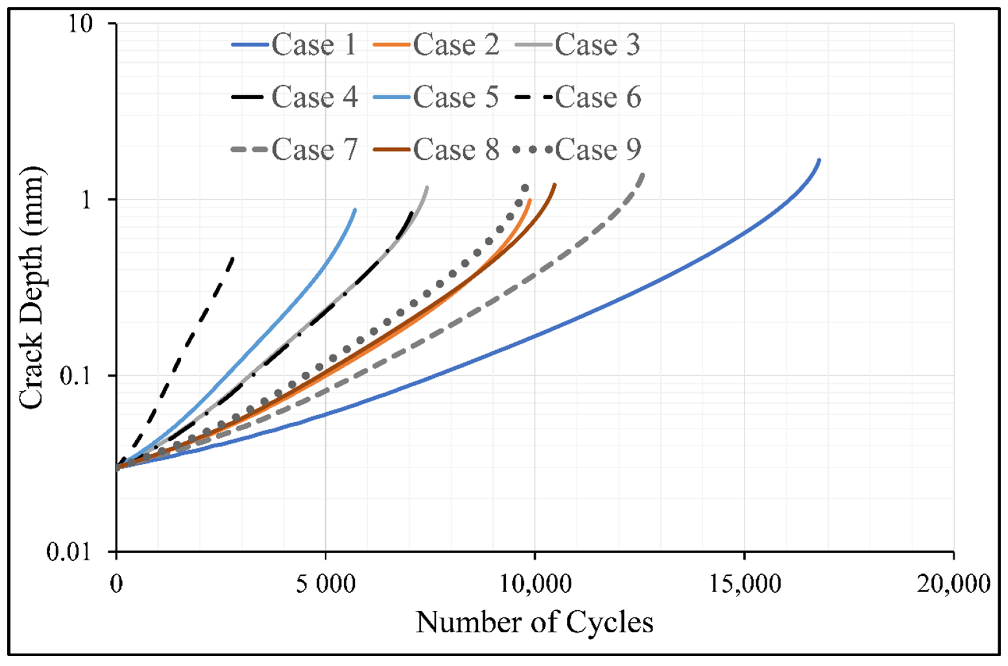
| d (mm) | Case | Surface Machined | T (mm) | Computed Life (Cycles) | |||
|---|---|---|---|---|---|---|---|
| Semi-Circular Surface Crack | Reduction * in Fatigue Life (% diff) | Corner (Quadrant) Crack | Reduction * in Fatigue Life (% diff) | ||||
| 1.57 | 1 | No | 0 | 16786 | Baseline | 16428 | Baseline |
| 2 | Yes | 0.071 | 9877 | 41.2 | 9610 | 41.5 | |
| 3 | No | 0.142 | 7418 | 55.8 | 8018 | 51.2 | |
| 4 | No | 0.1815 | 7112 | 57.6 | 6896 | 58.0 | |
| 5 | Yes | 0.1815 | 5699 | 66.0 | 6162 | 62.5 | |
| 6 | No | 0.363 | 2888 | 82.8 | 4971 | 67.7 | |
| 2.42 | 1 | No | 0 | 16786 | Baseline | 16428 | Baseline |
| 7 | No | 0.071 | 12585 | 25.0 | 13270 | 19.2 | |
| 8 | Yes | 0.071 | 10464 | 37.7 | 10578 | 35.5 | |
| 9 | No | 0.142 | 9765 | 41.8 | 10235 | 37.7 | |
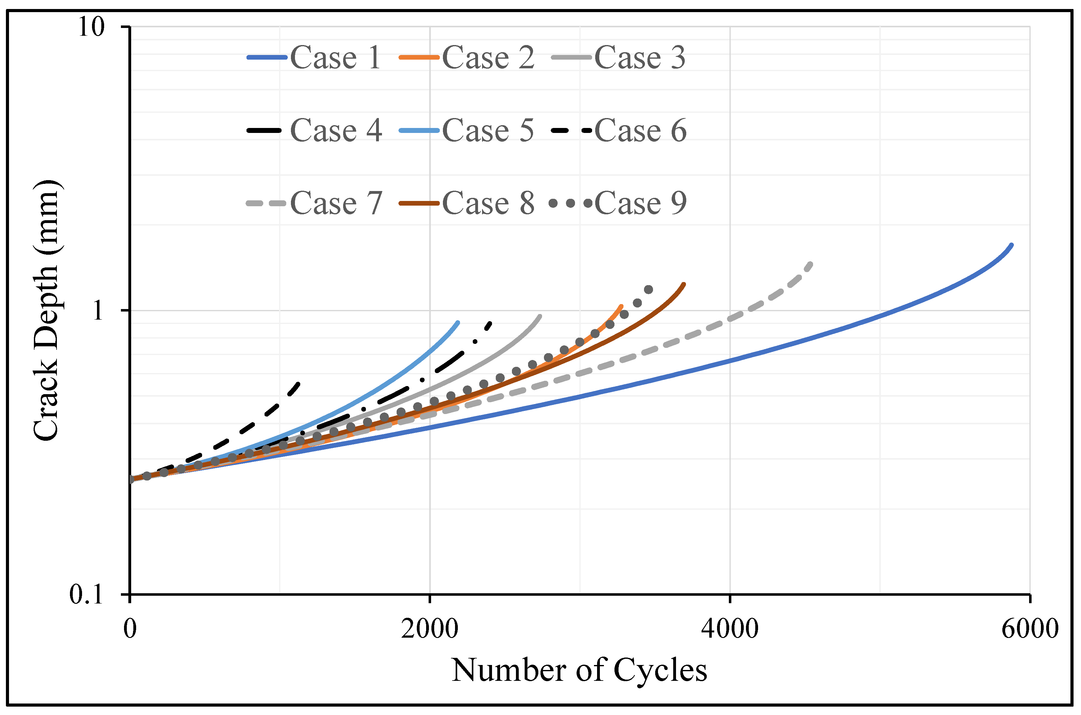
| d (mm) | Case | Surface Machined | T (mm) | Computed Life (Cycles) | |||
|---|---|---|---|---|---|---|---|
| Semi-Circular Surface Crack | Reduction in Fatigue Life (% diff) from the Baseline | Corner (Quadrant) Crack | Reduction in Fatigue Life (% diff) from the Baseline | ||||
| 1.57 | 1 | No | 0 | 5875 | Baseline | 5639 | Baseline |
| 2 | Yes | 0.071 | 3275 | 44.3 | 3401 | 39.7 | |
| 3 | No | 0.142 | 2746 | 53.3 | 3058 | 45.8 | |
| 4 | No | 0.1815 | 2399 | 59.2 | 2186 | 61.2 | |
| 5 | Yes | 0.1815 | 2186 | 62.8 | 2468 | 56.2 | |
| 6 | No | 0.363 | 1135 | 80.7 | 1924 | 65.9 | |
| 2.42 | 1 | No | 0 | 5875 | Baseline | 5639 | Baseline |
| 7 | No | 0.071 | 4536 | 22.8 | 4701 | 16.6 | |
| 8 | Yes | 0.071 | 3693 | 37.1 | 3883 | 31.1 | |
| 9 | No | 0.142 | 3463 | 41.1 | 3730 | 33.9 | |
Publisher’s Note: MDPI stays neutral with regard to jurisdictional claims in published maps and institutional affiliations. |
© 2022 by the authors. Licensee MDPI, Basel, Switzerland. This article is an open access article distributed under the terms and conditions of the Creative Commons Attribution (CC BY) license (https://creativecommons.org/licenses/by/4.0/).
Share and Cite
Peng, D.; Jones, R.; Ang, A.S.M.; Champagne, V.; Birt, A.; Michelson, A. A Numerical Study into the Effect of Machining on the Interaction between Surface Roughness and Surface Breaking Defects on the Durability of WAAM Ti-6Al-4V Parts. Metals 2022, 12, 1121. https://doi.org/10.3390/met12071121
Peng D, Jones R, Ang ASM, Champagne V, Birt A, Michelson A. A Numerical Study into the Effect of Machining on the Interaction between Surface Roughness and Surface Breaking Defects on the Durability of WAAM Ti-6Al-4V Parts. Metals. 2022; 12(7):1121. https://doi.org/10.3390/met12071121
Chicago/Turabian StylePeng, Daren, Rhys Jones, Andrew S. M. Ang, Victor Champagne, Aaron Birt, and Alex Michelson. 2022. "A Numerical Study into the Effect of Machining on the Interaction between Surface Roughness and Surface Breaking Defects on the Durability of WAAM Ti-6Al-4V Parts" Metals 12, no. 7: 1121. https://doi.org/10.3390/met12071121
APA StylePeng, D., Jones, R., Ang, A. S. M., Champagne, V., Birt, A., & Michelson, A. (2022). A Numerical Study into the Effect of Machining on the Interaction between Surface Roughness and Surface Breaking Defects on the Durability of WAAM Ti-6Al-4V Parts. Metals, 12(7), 1121. https://doi.org/10.3390/met12071121