Article

Experimental Research on the Thermal-Consolidation Compound Forming of Thermosetting Fiber Metal Laminates Design for Complex Structures with Variable Curvature

1
Beijing National Innovation Institute of Lightweight Ltd., Beijing 100083, China
2
State Key Laboratory of Advanced Forming Technology and Equipment, China Academy of Machinery Science & Technology, Beijing 100044, China
3
School of Mechanical Engineering, University of Science & Technology Beijing, Beijing 100083, China
4
Research Institute for Structure Technology of Advanced Equipment, Hebei University of Technology, Tianjin 300401, China
*
Author to whom correspondence should be addressed.
Metals 2022, 12(6), 935; https://doi.org/10.3390/met12060935
Submission received: 30 April 2022 / Revised: 20 May 2022 / Accepted: 27 May 2022 / Published: 29 May 2022
(This article belongs to the Special Issue Innovative and Flexible Sheet Forming Technologies)

Abstract

:
The glass fiber-reinforced metal laminates (GLARE) cannot be used to form complex laminate structures in the aerospace industry, because there is substantial variation in the plasticity of the heterogeneous materials. Hence, a compound process for composite materials based on the thermoforming technology for aluminum alloy and fiber-reinforced metal laminates (FMLs)-forming technology was proposed; it contains solution heat treatment, thermoforming, quick cold die quenching, artificial aging integrated process (HFQ), and the thermal consolidation of fiber-reinforced metal laminates, and it is named the HFQ-FMLs forming process. In order to test and judge the effect of the heat treatment on the properties of the materials obtained by the new technology, the pure metal sheet and the three kinds of HFQ-FMLs composite laminates fabricated with the different layup method were assessed with the Vickers hardness test and the Charpy impact test at the same time, and they were labeled #1, #2, #3, #4, respectively. In the Charpy impact test, in order to obtain accurate data, the shape and fixing position of the specimen was optimized so that the gap direction was parallel to the loading direction. After the heat treatment, the properties of the aluminum alloy were improved, the hardness will affect the energy absorption of the laminates, and the relationship between the thickness, hardness and impact properties will be analyzed. The hardness test results are 39.9 HV, 37.5 HV, 37.4 HV, 37.1 HV which indicates the pure metal sheet had the greatest hardness, and the greater the thickness of fiber layer, the lower was the hardness of the HFQ-FMLs composite laminate. The impact resistance of the HFQ-FMLs composite laminates was about two times of the pure metal sheet for the same thickness, and the values are 2.3 J, 4.8 J, 4.8 J, 4.8 J, respectively. In addition, the method of laying the fiber layer had no effect on the impact resistance of the composite laminates. For the novel composite laminates subjected to different cutting processes, the scanning electron microscope (SEM) results for the incision morphology suggest that the water cutting process ensures the structural integrity of the composite laminates after the edges’ and holes’ cutting procedures, and the performance maintains continuity.

1. Introduction

Fiber-reinforced metal laminates (FMLs) refer to a hybrid structure system that is formed by alternately laying resin-based fiber sheet and thin aluminum alloy sheet. As a novel, high-efficiency, low-cost and lightweight composite structural material, FMLs have the dual advantages of metal and advanced composite materials [1,2,3,4], and they exhibit a remarkable integration of structure and performance. FMLs display decent electrical shielding characteristics, thermal insulation, sound absorption, shock absorption, and electrical insulation characteristics. Therefore, they are promising materials for the structure of next-generation aircrafts [5,6,7,8]. Three types of FMLs were widely used in commercial applications, namely aramid-reinforced aluminum laminates (ARALL), glass fiber-reinforced metal laminates (GLARE), and carbon fiber-reinforced aluminum laminates (CARALL). In general, the manufacturing costs and complexity of GLARE laminates are both higher than those of the aluminum alloy sheet. However, compared with the metal structures, GLARE has a lower surface density, longer service life and simpler inspection and maintenance during service, which currently make GLARE to be the most mature and widely applied of the FMLs [9,10,11]. In addition, for the same thickness, the GLARE laminate is 15% to 30% lighter than the aluminum sheet. In future, the GLARE will be used in the aircraft cargo floors of Boeing 777, aircraft engine cowlings, bonded GLARE patch repair, aircraft stiffeners of various shapes, cargo containers, and seamless GLARE tubes [12,13,14,15].
The aluminum alloy currently used in the aerospace field is primarily 2000 aluminum–lithium alloy. Owing to its lightweight and high strength, the alloy can better accomplish the lightweight task of a rocket’s structural components; enhancing the structural strength by 40% and reducing weight by 10%. However, the literature suggests that for a sheet of the same thickness, the GLARE laminate can reduce the weight by 15% to 30%, compared with the aluminum sheet of same volume. However, the rigidity of the GLARE laminate may be 15% lower than that of the aluminum alloy. Because of the rigidity limitation of metal materials, it is feasible to develop new high-performance GLARE laminates. Compared with the traditional aluminum alloy sheet, the fiber-reinforced laminate material has a higher ultimate strength and elastic modulus. Consequently, for the aerospace structural components with a large curvature, several problems, such as large rebound and lower fracture strain, will happen using the conventional plastic forming technology. For the manufacturing technology of the structural components with fiber metal laminates, there are two, commonly used major schemes. The first one can be described as the plies of the fiber-reinforced polymeric materials were dealt with by laying them with the metal alloy sheets, then the heterogeneous structural materials underwent solidification treatment in order to obtain the FMLs; FMLs, which are considered to be a composite material, will undergo plastic deformation at room temperature. However, this process is only suitable for the simple structural parts with a small curvature, including stamping craft, roll forming, and the shot peening process. The second is that using the laying technology of the composite materials, the thin aluminum alloy sheets and resin-based fiber prepreg are deposited alternately on the mold, then the laminates of a certain shape are treated with hot curing in the autoclave, and the parts can be obtained all at one time. This route contributes to the forming of the complex components with a large curvature, such as the vacuum bag-autoclave forming and “3A” forming processes which are the typical representatives. However, these methods are unable to form laminate sheets with large-scale complex structures; the innovative forming technology needs to be further developed.

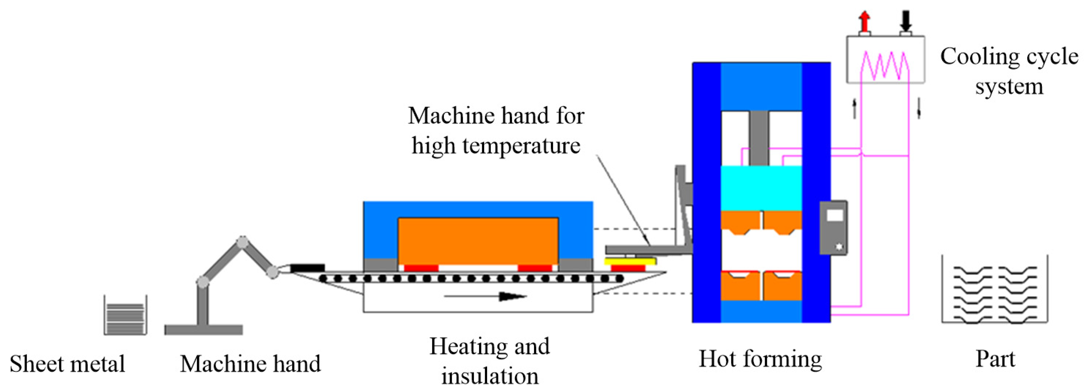
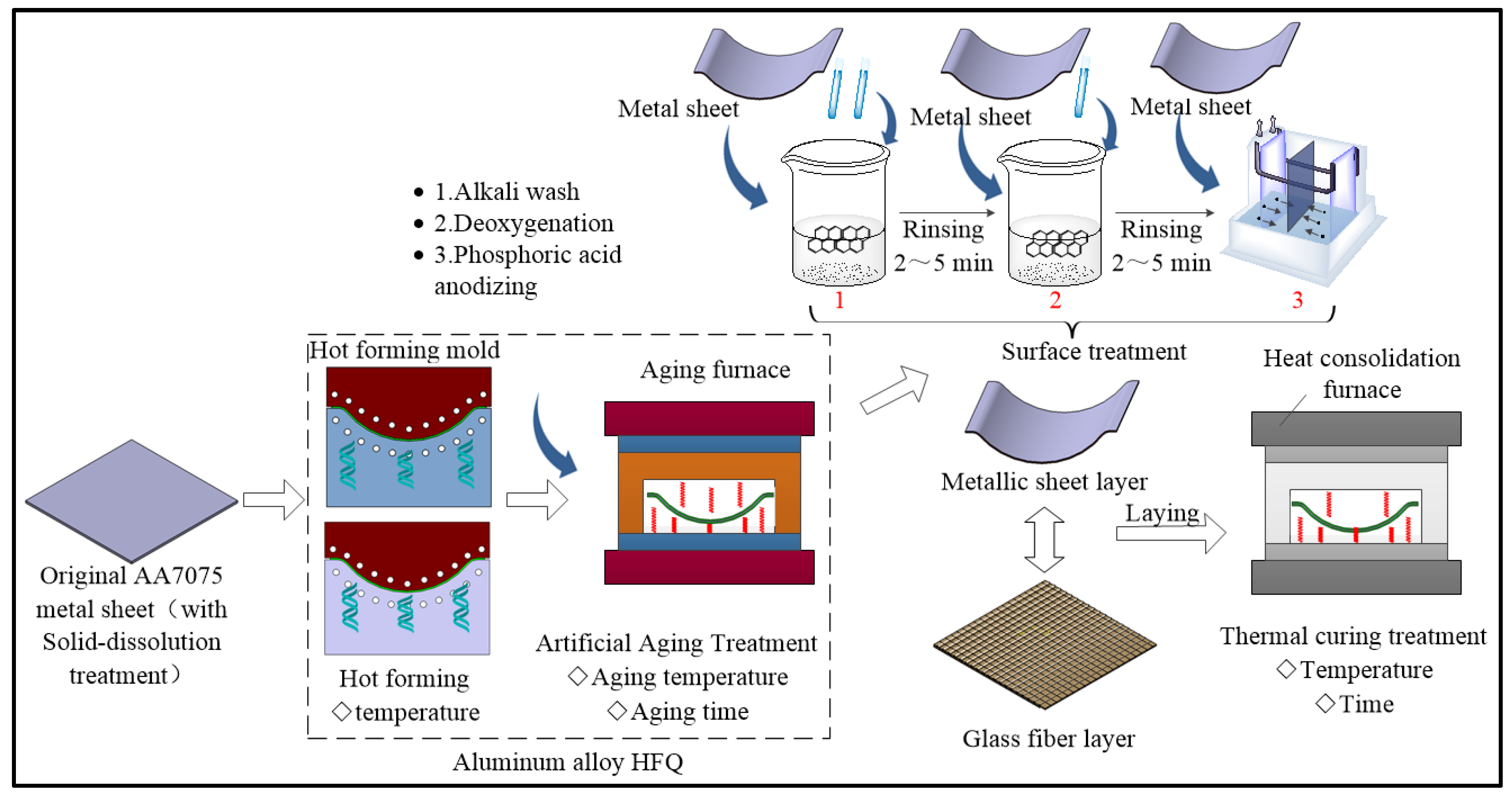
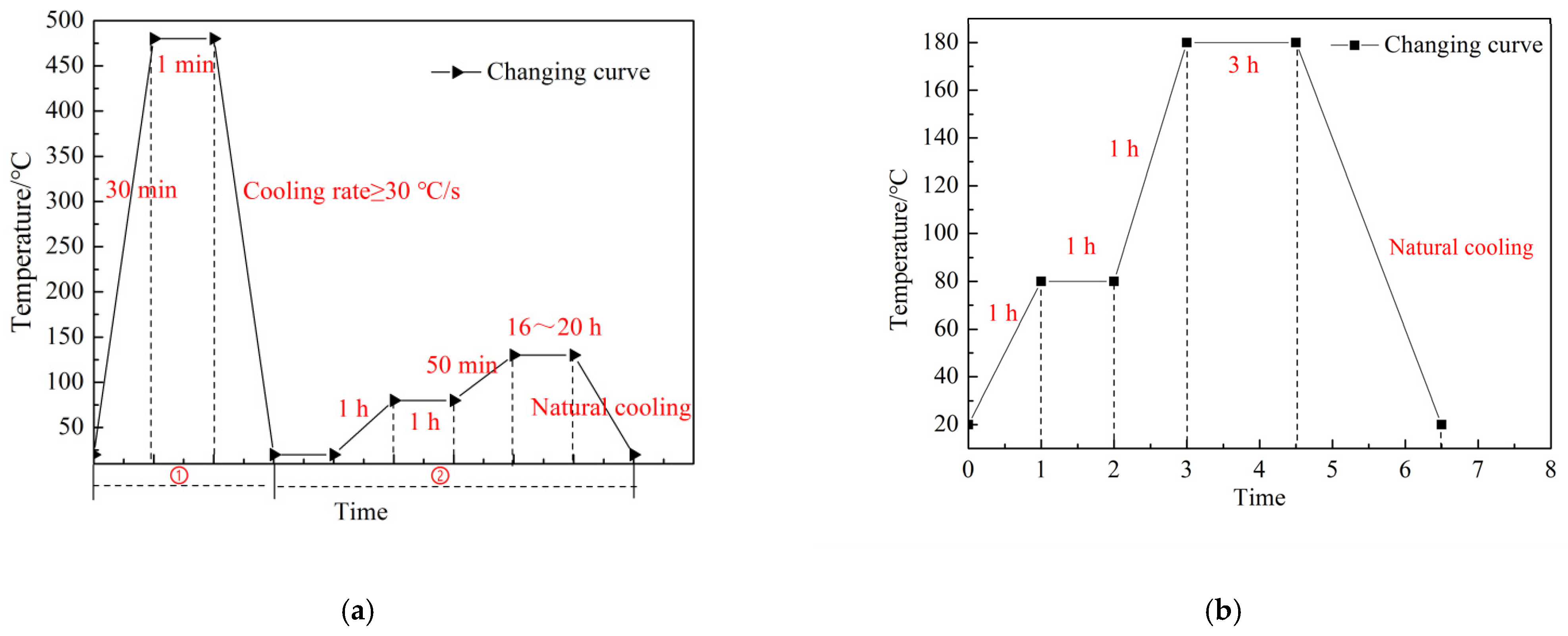
2. The Proposition of Compound Forming Process

The 7000 series aluminum alloys belong to the Al-Cu-Mg series alloys, which are heat-treatable reinforced aviation alloys, the specified strength that can be obtained by continuous heat treatment systems includes the solid–dissolution process, quenching, and artificial aging [16,17,18,19,20], and their strength is higher than that of the 2000 series aluminum alloys. Therefore, the design rigidity of the composite laminates can be achieved accordingly, to improve the rigidity of the 2000 series and 7000 series aluminum alloys using the successive heat treatment route. The heat-forming-quenching (HFQ) technology for aluminum alloy is a multi-field coupling process, it sequentially involves the solid–dissolution treatment of the original metallic sheets, rapid thermoforming, quick quenching in the mold, and the artificial aging. Because of the hot environment, the plasticity of the aluminum alloy plates improved and the deformation increased in the HFQ process. With the help of the quick quenching and artificial aging treatment, the mechanical properties can be affected as the reinforcing phase diffuses and precipitates at the same time. Consequently, the HFQ technology has become the current research focus for heat-treatable aluminum alloy, it can not only get the precise structure size, but also, simultaneously, the strength enhancement. The HFQ technology route is presented in Figure 1.
Thinking of the metallic part obtained by the HFQ process as the metal layer, the fiber/epoxy polymeric materials were laid with the metal plates, according to certain methods, and the whole composite structure was obtained. Setting up the optimal heating temperature and time, the integration material was consolidated in the vacuum furnace (Easy Composites Ltd., Park Hall Business Village, ST3 5XA, Stoke-on-Trent, UK), and the final product was obtained when the furnace cooled. Because the whole process includes the HFQ part and the laying technology of the fiber prepregs, it was innovatively named the HFQ-FMLs compound technology, and the technical schematic diagram is shown in Figure 2.
In the solid–dissolution process, the fiber/epoxy prepreg developed because of heat consolidation obeying the temperature–time curve, and the metallic plates dealt with the first artificial aging process will undergo changes in microstructure and properties at the same time. So, a variety of the composite laminates underwent some mechanical tests to verify the rationality of the compound forming process, and to analyze the regularity effect of the structure types. The hardness of the metal sheets and the lay-up of the composite laminates will affect the absorption energy, and the lay-up of the composite laminates has an effect on the hardness of the whole composite laminates, conversely, so that the hardness test experiment, impact resistance experiment, and the relationships between hardness, thickness, and impact resistance were studied at the same time. By using the hardness test, impact test, and the cutting process test, the hardness, energy absorption, and suitable cutting process of the new structural materials were explored, with consideration of the fiber laying method. Impact performance is an important performance parameter for aerospace structural parts. There are multiple factors that cause impact damage, such as fallen repair tools, collision structures between service vehicles or cargo and cargo, bird strikes, and hail [21,22,23,24]. Jun Liu [25] studied the impact performance of thermoplastic and thermosetting woven carbon fiber composites under the action of high-speed soft and hard impacting objects using light-air gun experiments. George SE Bikakis [26] investigated the dynamic response of the thin circular clamped GLARE (glass-reinforced) fiber-metal laminates, subjected to low-velocity impacts by a lateral hemispherical impactor that strikes at the center with constant kinetic energy.

3. Experiments and Results Analysis

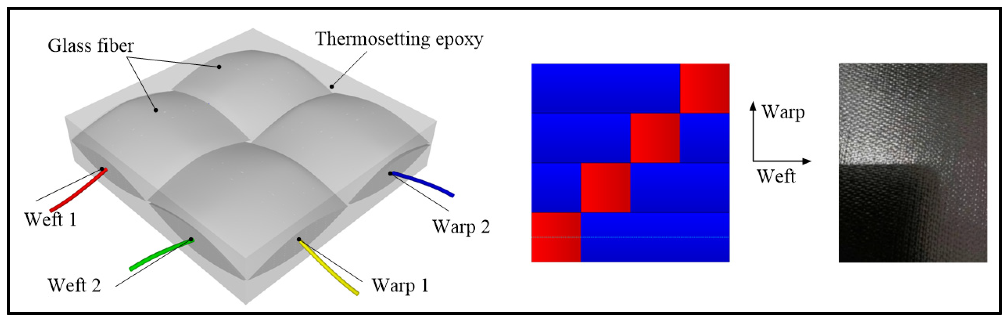
3.1. Preparation of Materials

The research object in this manuscript is the glass fiber-reinforced metal laminates which consist of two layers of 7075 aluminum alloy sheets and one layer of prepreg; the structure model is referred to as GLARE1-2/1.0-0.29 [27,28]. Among them, the thickness of the metal plates is 1.0 mm, and they were processed with heat treatment, of which the route is shown in Figure 3a. the first step is the solid–dissolution and quenching, the second step is artificial aging.
The thickness of the thermosetting prepreg in the middle layer is 0.29 mm, and it was woven by the method of 1/3 broken twill, which is shown in Figure 4. The metal layer and the fiber layer were assembled, based on the laying of the prepreg and the adhesive bonding process, then all of the laminates were carried out of the heat consolidation treatment, of which the route is shown in Figure 3b, and the experiment materials were finally obtained.
After the treatment, the mechanical characters of the metallic plates are: the tensile strength is 384 MPa and elongation is 17.56% which are improved compared to the original aluminum alloy by 43.8% and 32.03%, respectively. The mechanical characters of the fiber resin mixture are shown in Table 1.

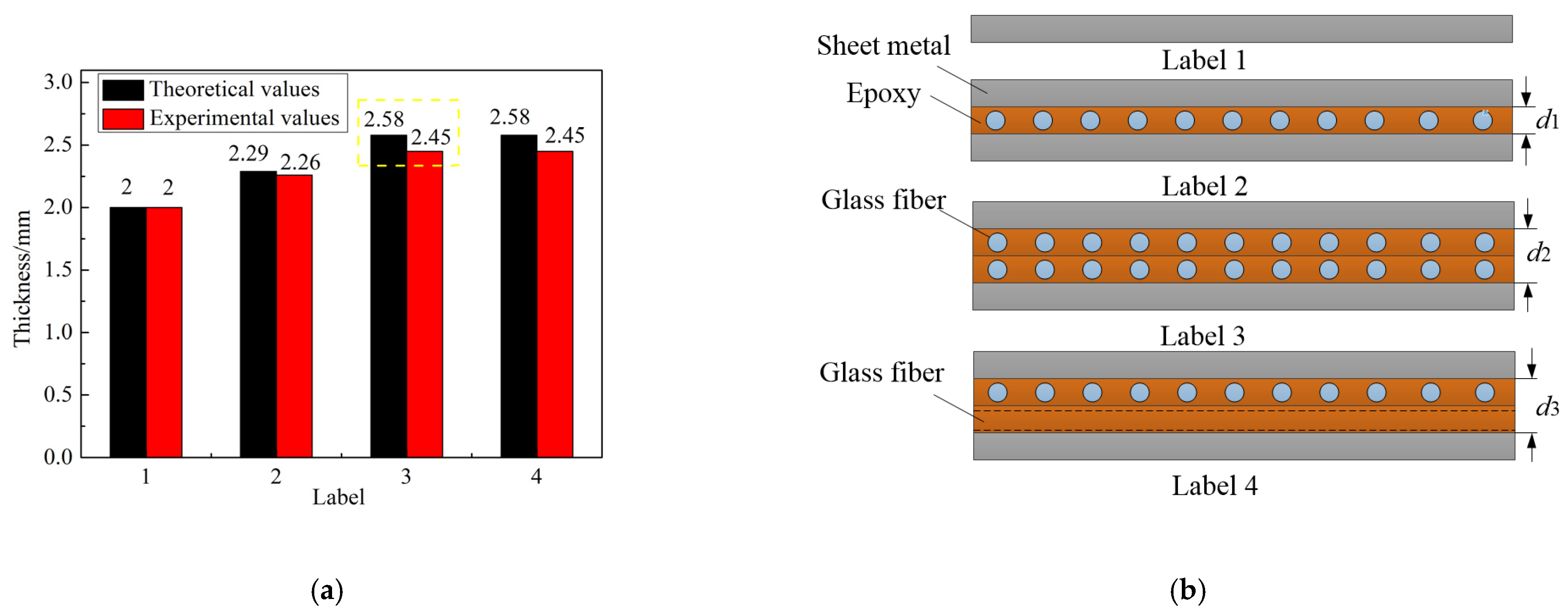
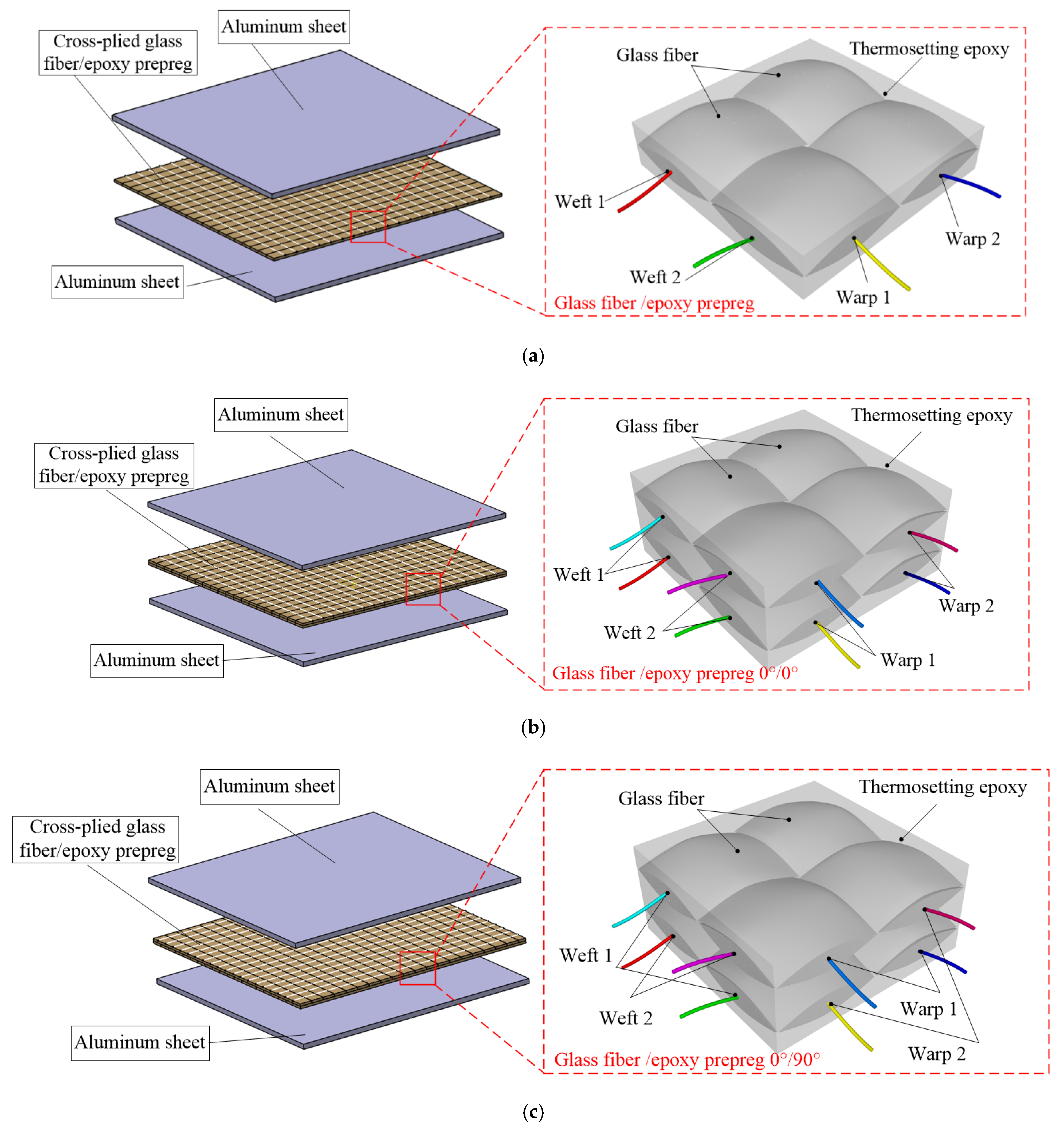
3.2. Structural Design
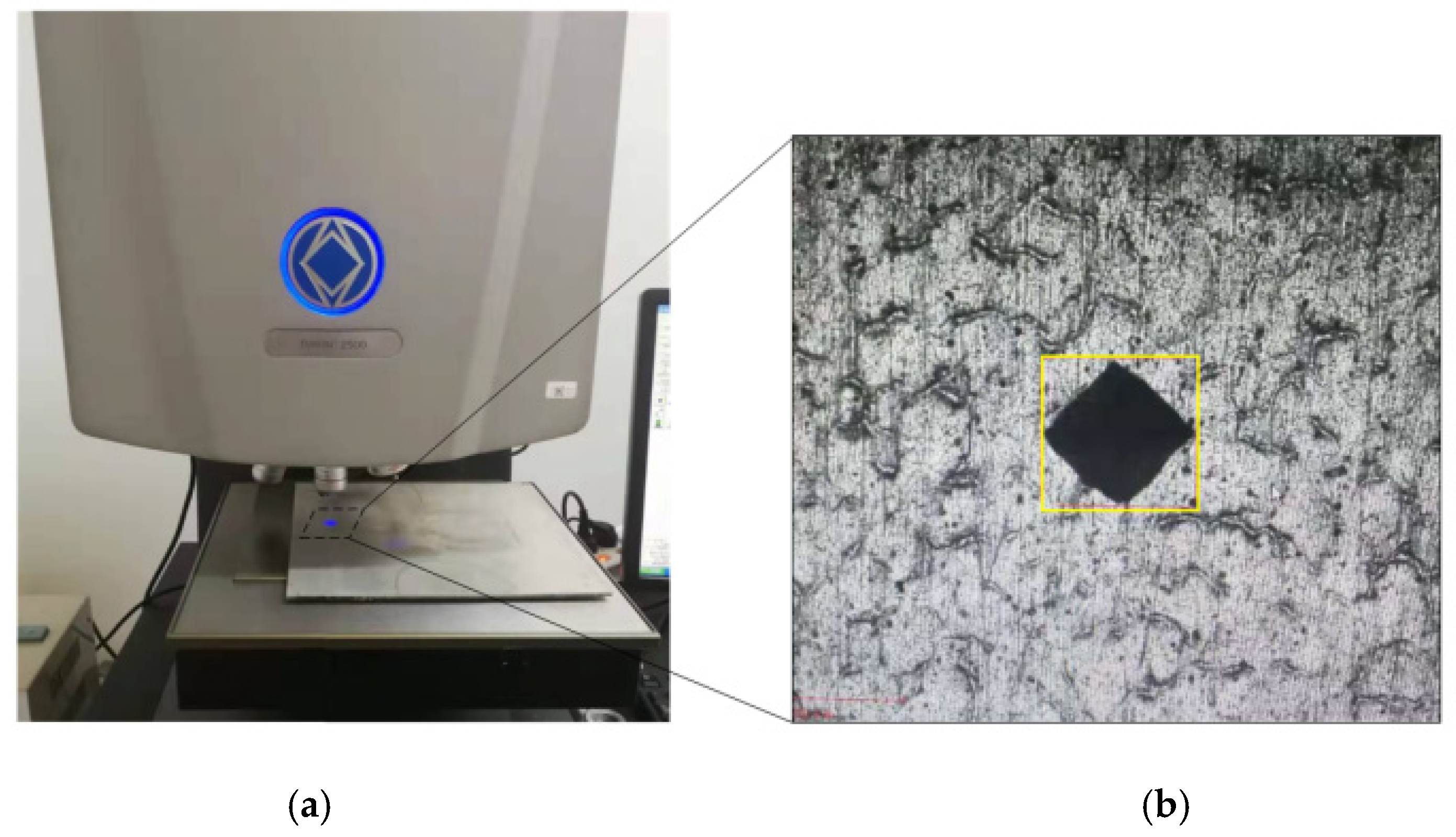
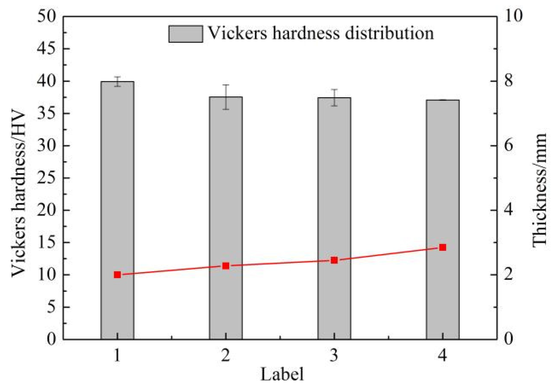
The laying method of the fiber prepreg had a great effect on the mechanical properties of the FMLs, it included the layer number of the prepregs the layer direction, and so on. To study the effect regularity which was affected by the fiber laying scheme, three kinds of FMLs with different structures were prepared, and special test schemes were performed. The first one can be described as Al/0/Al, it refers to single-layer glass fiber, and the direction of the fiber is the same as the rolling direction of the sheet metal. The second one is Al/0/0/Al, which is double-layer prepreg. For the Al/0/0/Al structure, the fibers are syntropic and its direction is along the rolling direction of the metal plate. The last one is the Al/0/90/Al structure, in which the directions of the fibers are orthotropic, one is along the rolling direction and the other is vertical to the rolling direction. The three kinds of structure are labeled #2, 3# and #4, respectively, they are shown in Figure 5 and the metal layers are labeled #1.
To verify the capabilities of the new fiber prepregs and analyze the effect regularity of the fiber laying programs, the hardness test and impact resistance test for the pure aluminum alloy sheets and the three kinds of FMLs were completed. Because of the fiber/epoxy polymeric layer which interacts with the tools, the cut section quality will be affected when using the traditional machining means. So, four kinds of cutting technologies were carried out on these composite laminates, and the cutting organization appearances were simultaneously observed using the SEM experiment (JEOL, City of Tokushima, Tokyo, Japan).

3.3. Hardness Test

The network structure of the fiber composites and the adhesive character of the epoxy can contribute to the improvement of the impact resistance of the FMLs, and the proportions of the fiber especially play a main role. Meanwhile, the hardness of the FMLs will be affected by the soft features of the epoxy, because the epoxy can increase its resistance and reduce the force. When the plies of the fiber-reinforced polymeric materials are laid between the thin sheets of metal alloys, because of the compressive force from the outside environment, the different layers of the matrix system will insert into each other, which will cause the proportion of the fiber polymers and the thickness of the composites to change, instead of the physical stacking, the hardness and impact resistance for the FMLs show an irregularity. Considering the stacking state of the prepregs to be the medium, the relationship between the hardness and impact resistance will be established, and the impact character of the new structural fiber metal laminates will be evaluated and compared by simply testing the hardness values. So, first the Vickers hardness experiments for the four kinds of materials were implemented, the experiment device is TUKON 2500, the loading range is 10 gf–50 kgf, the force accuracy is ±1.5% < 200 g, ±1% > 200 g, the holding time is 1–999 s, and the experiment process and measuring points are shown in Figure 6. In order to obtain accurate data, areas with higher flatness are required, and the specimen that was selected was the square sheet, of which the dimensions are 180 mm × 180 mm.
When the experiments were over, the actual thickness distribution was compared with the theoretical values, which are shown in Figure 7. At the same time, the measurement results and average values of the hardness are illustrated in Figure 8, and it also demonstrates the relationship between the hardness and the thickness of the fiber metal laminates.
According to observations of the experimental results and the theoretical results of the thickness shown in Figure 7a, it proved that the FMLs were not just physically assembled with the fiber layers and sheets of aluminum alloys. In order to increase the bonding force between the metal layers and the fiber epoxy prepreg plies, the surface of the metal alloy was dealt with by chemical treatment, and there were lots of pits on the metal surface which made the surface roughness of the aluminum alloy enlarge. Because of the compressive effect and the pitted character of the metallic layers, the epoxy from the neighboring layers integrated with each other, and the epoxy inserted into the metal surface, which reduced the total thickness of the heterogeneous composite materials. Combined with the distributions of Vickers hardness in different cases, which are shown in Figure 8, the distribution trends of the thickness and the Vickers hardness are opposite. This is helpful for the structural design of the composite laminates, considering the required properties.

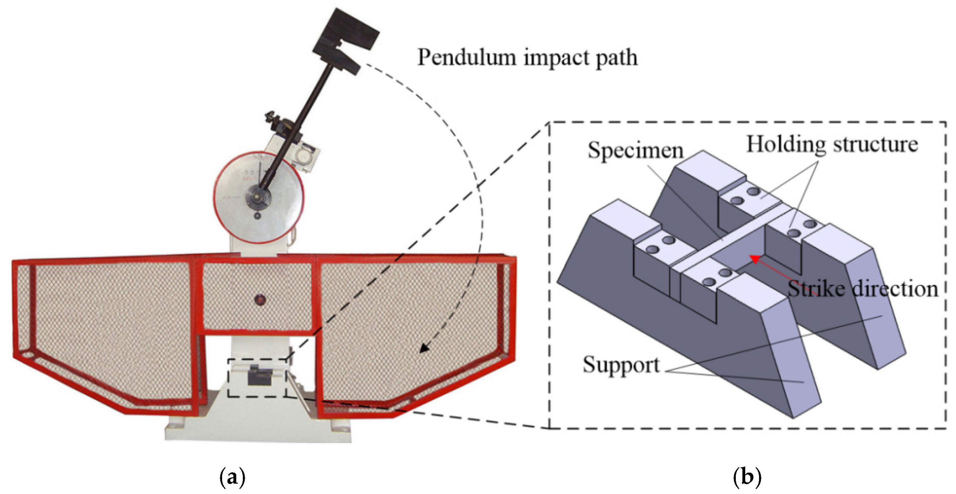
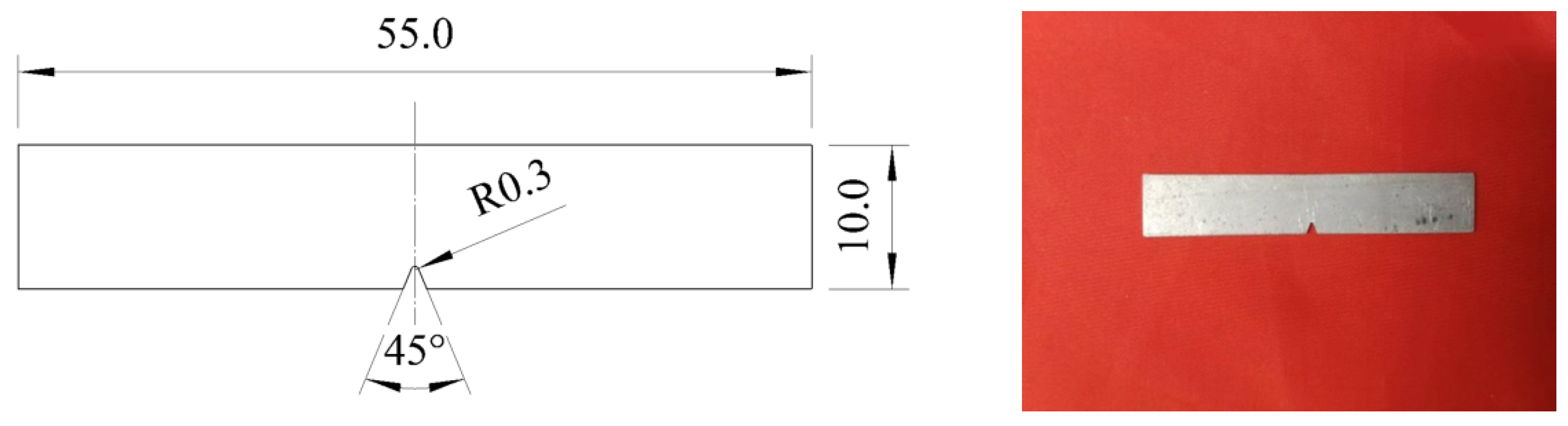
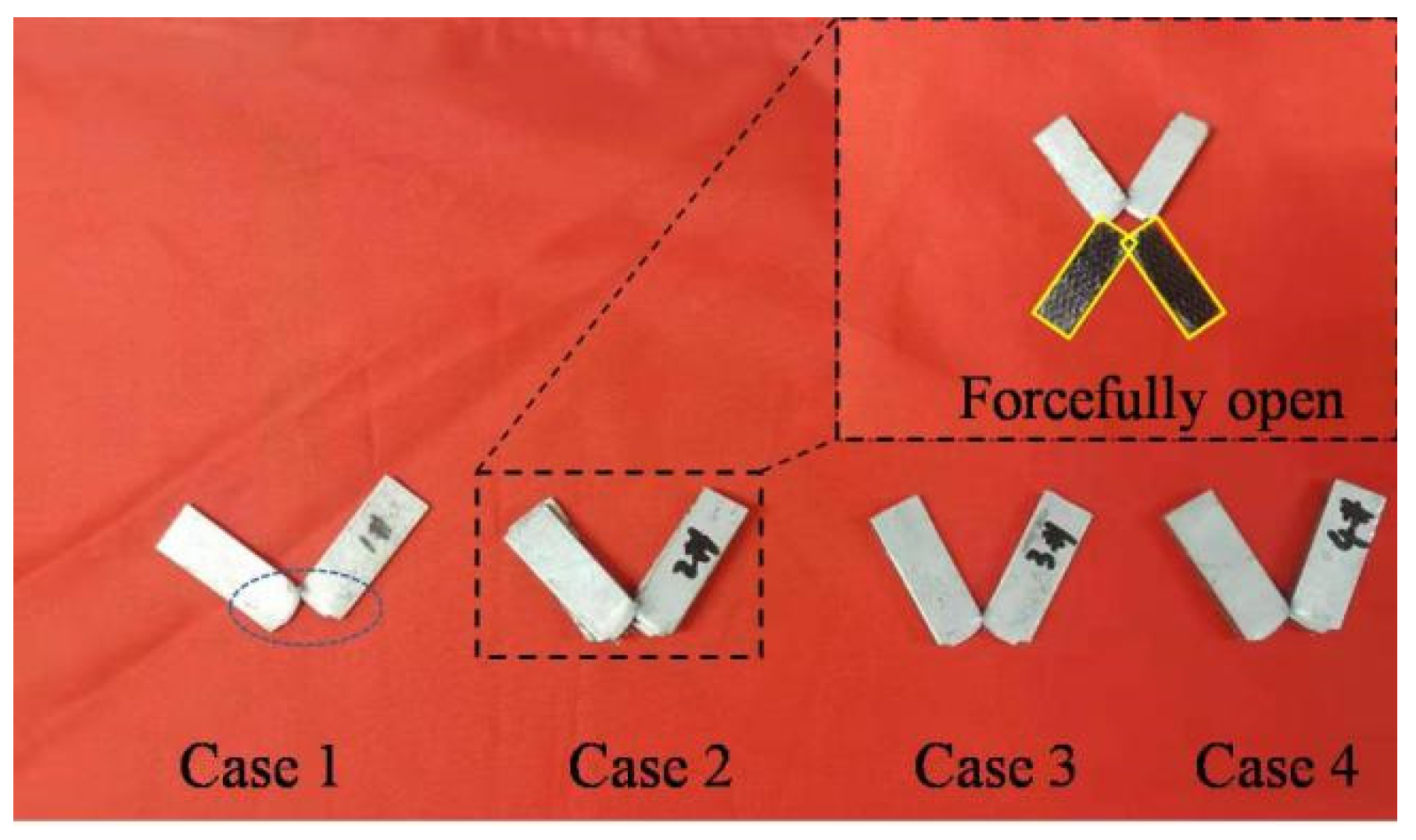
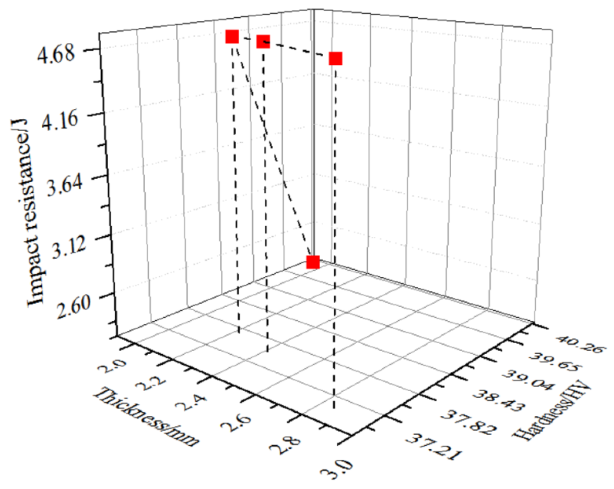
3.4. Impact Resistance Test

In order to test and verify the excellent impact resistance of the composite laminates formed by the HFQ-FMLs compound technology, the Charpy pendulum impact test method for metallic materials was conducted on the four kinds of sheets. The test equipment was the JB-300B impact testing machine, which was manufactured according to the inspection of the pendulum impact tester. The impact testing scheme was implemented in accordance with the national standard metal Charpy notch impact test method, and the test equipment is shown in Figure 9a. Because the composite laminates were metal plates, the specimens were processed into lath shapes rather than the rod parts for the traditional impact test. Consequently, in order to distinguish the destruction degree, it was necessary to firmly hold the test piece, prevent its movement during the test, and to obtain accurate experiment data, the clamp tooling was improved and redesigned. The effect drawing of the device is shown in Figure 9b.
In the test process, the potential energy difference of the pendulum before and after the impact test was displayed on the dial, denoting the absorbed energy of the specimen, which is also the impact energy. The operation adopted a semi-automatic control, so it was easy to operate, and had high working efficiency. The remaining energy after the impact could automatically raise the pendulum, and it can reflect superiority in the continuous impact test of the specimens. The dimensions of the four specimens are expressed as width × length × thickness, and the values are 10 × 55 × 2.4 (mm3), 10 × 55 × 2.6 (mm3), 10 × 55 × 2.7 (mm3), and 10 × 55 × 2.9 (mm3), which are shown in Figure 10.
After all of the impact experiments, the test pieces were displayed in Figure 11. According to the calculation and transformation of the experiment data, the impact energies of the four types of sheet specimens were demonstrated on the dial, and the values were 2.3 J, 4.8 J, 4.8 J, and 4.8 J, respectively. The distribution of impact energy and the relationship between thickness and impact energy were shown in Figure 12.
According to our observation of the specimens shown in Figure 11, it was found that all of the specimens were broken, the experiment process is reasonable, and the data are accurate. Combined with the defect cases, it was analyzed from the relationship tendency of thickness, hardness, and energy absorption in Figure 12 that the composite laminates have a better impact resistance due to the addition of the fiber-reinforced laminates, and the energy absorption was about two times that of the aluminum alloy sheet. Meanwhile, the number of fiber laminate layers and the layup method had little effect on the impact resistance of the HFQ-FMLs composite laminates, but the damage defects were different. The failure mode of the single-layer fiber-reinforced composite laminates after the impact test was the fracture of the fiber layer and metal sheet, and the synchronous peeling between the two components. The failure modes of the double-layer fiber-reinforced composite laminates is mainly the damage of the fiber layer and metallic plate, while, because the adhesive strength between the two layers of prepreg is affected by the epoxy, the composites separation may occur, such as the case 3 and 4. For case 2, the separation exited between the two layers of fiber prepreg, and the heterogeneous materials at the same time, so it was judged to be improperly operated by humans. All of the above indicate that the epoxy bonding between the two-layer glass fiber weakened the joint strength of the whole structure. As a result, when there is a risk of exit fracture, the two components maintain integrity, which also suggests that the notched residual strength of the double-layer HFQ-FMLs composite laminates is better than that of the single-layer fiber composite laminates.

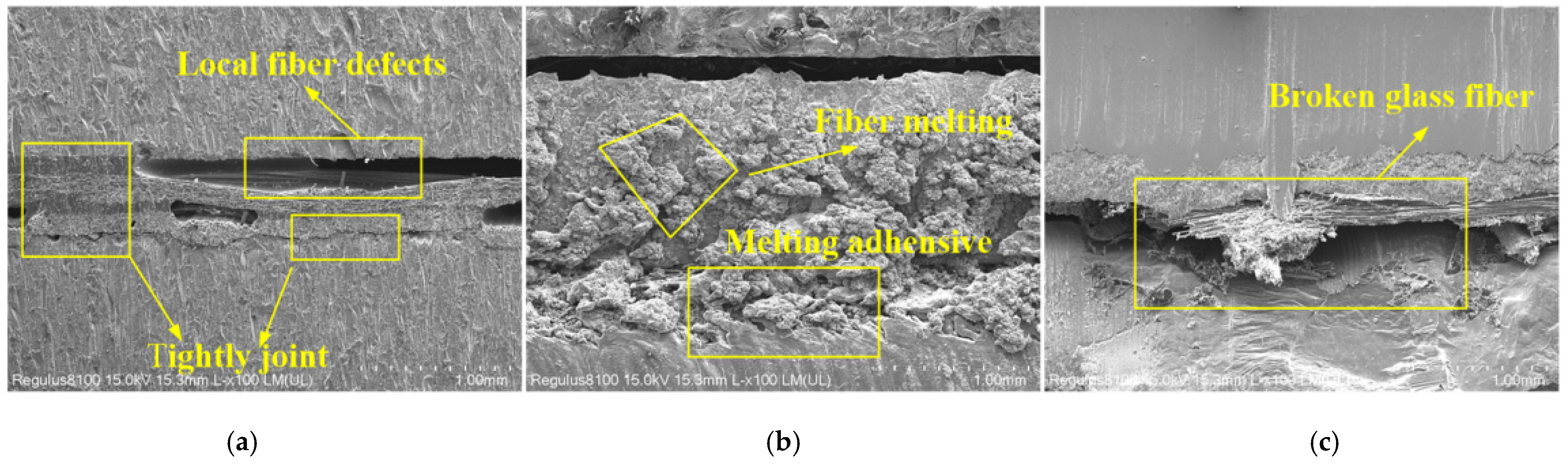
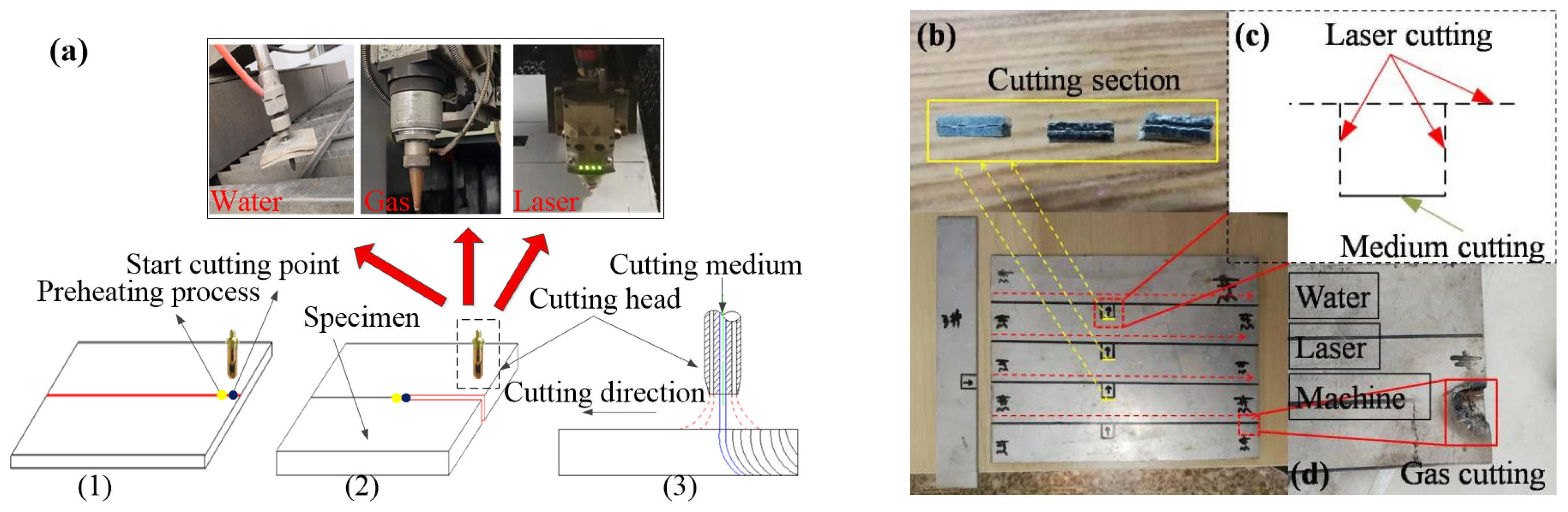
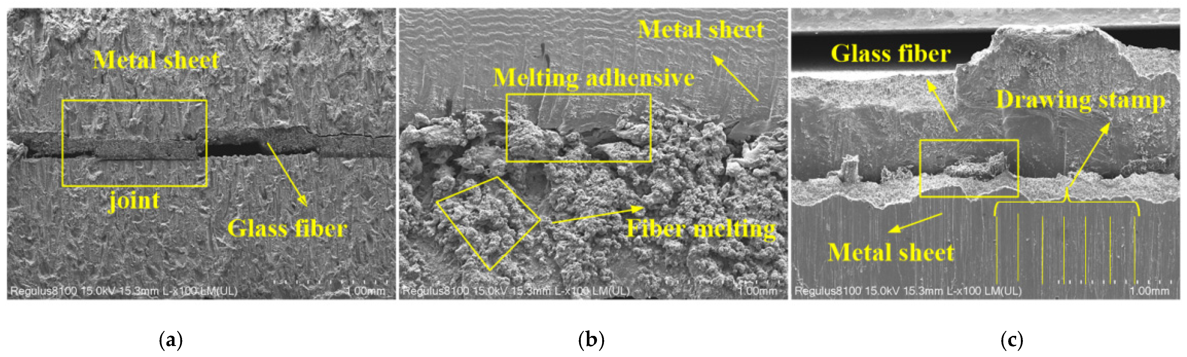
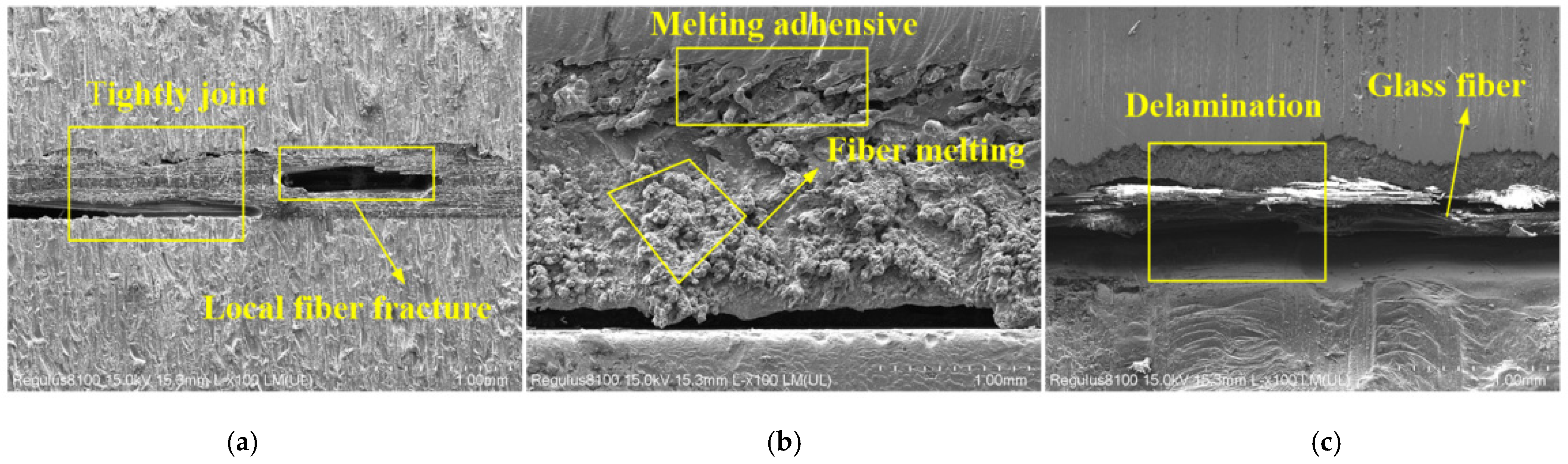
3.5. Cutting Process of Composite Laminates

Owing to the multi-material properties and the interaction mechanisms between the different materials for the composite laminates, when the parts were cut after the deformation, including the cutting of the edges and holes, the incision appearance and incision’s connection strength will be affected by the traditional cutting process. In order to find a suitable cutting process for the HFQ-FMLs composite laminates and get the qualified parts, experiments with mechanical cutting, laser cutting, flame cutting, and water cutting method for the composite material were carried out, and micro-morphology observations of the cutting, using the SEM experiment, was the main judgement method. According to the distribution analysis of the morphology, the connection quality of the composite materials were researched, and the integrity of material is judged too. For the last three cutting processes, the technical principle is similar, while the energy medium was different, it is high-energy laser beam, high-energy heat source, and high-speed liquid, in turn. The cutting processes are displayed in Figure 12, and the test pieces for cutting test are shown in Figure 13.
It can be seen from the flame machining results in Figure 13, the cutting quality of the specimen was extremely poor due to the high flame temperature and its operation scope. So, this cutting method is not suitable for the subsequent edges’ and holes’ cutting for the HFQ-FMLs composite laminates, and it will not be considered. Following adjustments to the processing path and craft parameters, the SEM observation results of the section micro-morphology after the three different cutting experiments were analyzed, which are shown in Figure 14, Figure 15 and Figure 16.
According to the observations arising from the micro-morphology of the bonding surface in different situations, shown in Figure 14, Figure 15 and Figure 16, it was concluded that the flow direction of the material along the section was vertical to the sheet metal, and it was due to the effect direction of the energy medium. After the water cutting process at room temperature, because of the continuous impact process with high velocity, some discontinuous void defects were experienced, but the two kinds of materials were tightly bonded in most areas. It was explained that the discontinuous void defect may be caused by the air between the heterogeneous materials when the HFQ-FMLs composite laminates were prepared. After the laser cutting process, it was seen that the fiber layer was burned when observing the bonding surface, which would affect the appearance of the incision, damage the continuity of the fiber layer near the cut, and the service performance of the composite laminate would ultimately be weakened. The morphology observation of the bonding surface after machinery cutting process indicates that the metal sheet had some adhesion with the cutting tool. The same as with the laser cutting, the discontinuous interaction between the two items will eventually affect the overall performance of the composite laminates. Therefore, with regards to the considerations of the product’s appearance and the continuity of the performance, the water cutting process ensured adhesion between the fiber layer and metal sheet, and it is more suitable for the cutting of edges and holes for the composite laminates after HFQ-FMLs technology.

4. Conclusions

(1)
The hardness test results of the four plates indicate that the addition of glass fiber/epoxy resin reduced the hardness of the composite laminate, as compared to that of the pure metal sheet, and the greater the thickness of the fiber layer, the lower was the hardness. The hardness of the composite laminate with orthogonal fiber layup was less than that of the composite laminate with consistent fiber layup;
(2)
Standard impact test results indicate that the impact resistance of HFQ-FMLs composite laminates was better than that of the pure metal sheet, and the impact resistance of the composite laminates was independent of the number of fiber layers and the laying methods;
(3)
The observation of the cut morphology after different cutting processes shows that the water cutting process had a strong impact force, due to the high-speed liquid impact, the fiber and metal were cut at the same time while the two components were still in a tightly bonded state. Both laser cutting and machinery cutting led to different degrees of fiber layer damage, and the delamination between the two materials also occurred. Therefore, in order to ensure the material’s integrity, the water cutting process is more suitable for the subsequent cutting of edges and holes of the HFQ-FMLs composite laminate parts from now on.

Author Contributions

Q.Z. and F.S. put up the multi-filed compound forming technology and designed the experiments; Q.Z. designed the schemes of the impact performance test and cutting process of the composite laminates obtained by the compound forming technology; R.J. and Z.L. performed the metallographic and SEM experiments, and microstructure analysis; H.L. carried out the hardness measurement and analyzed the experiment results; Y.W. carried out the impact performance test, and analyzed the experimental data. All authors have read and agreed to the published version of the manuscript.

Funding

This work is supported by the Development Fund of the China Academy of Machinery Science and Technology Group (2021110032020659).

Data Availability Statement

Not applicable.

Conflicts of Interest

The authors declare no conflict of interest.

References

  1. Pawar, O.A.; Gaikhe, Y.S.; Tewari, A.; Sundaram, R.; Joshi, S.S. Analysis of the hole quality in drilling GLARE fiber metal laminates. Compos. Struct. 2011, 123, 350–365. [Google Scholar] [CrossRef]
  2. Soutis, C.; Mohamed, G.; Hodzic, A. Modeling the structural response of GLARE panels to blast load. Compos. Struct. 2012, 94, 267–276. [Google Scholar] [CrossRef]
  3. Moriniere, F.D.; Alderliesten, R.C.; Sadighi, M.; Benedictus, R. An integrated study on the low-velocity impact response of the GLARE fiber-metal laminate. Compos. Struct. 2013, 100, 89–103. [Google Scholar] [CrossRef]
  4. Yaghoubi, A.S.; Liaw, B. Thickness influence on ballistic impact behaviors of GLARE 5 fiber-metal laminated beams: Experimental and numerical studies. Compos. Struct. 2012, 94, 2585–2598. [Google Scholar] [CrossRef]
  5. Chen, S.J. Composites and airliner A380. Aeronaut. Manuf. Technol. 2002, 9, 27–29. [Google Scholar]
  6. Sang, Y.P.; Choi, W.J.; Choi, H.S. The effects of void contents on the long-term hygrothermal behaviors of glass/epoxy and GLARE laminates. Compos. Struct. 2010, 92, 18–24. [Google Scholar]
  7. Chai, G.B.; Manikandan, P. Low velocity impact response of fiber-metal laminates-A review. Compos. Struct. 2014, 107, 363–381. [Google Scholar] [CrossRef]
  8. Dursun, T.; Soutis, C. Recent developments in advanced aircraft aluminum alloys. Mater. Design. 2014, 56, 862–871. [Google Scholar] [CrossRef]
  9. Wu, X.R.; Guo, Y.J. Fatigue Life Prediction of Fiber Reinforced Metal Laminates under Variable Amplitude Loading. Strateg. Study CAE 1999, 1, 35–40. [Google Scholar]
  10. Krishnakumar, S. Fiber Metal Laminates-The Synthesis of Metals and Composites. Adv. Manuf. Process. 1994, 9, 295–354. [Google Scholar] [CrossRef]
  11. Young, J.B.; Landry, J.G.N.; Cavoulacos, V.N. Crack growth and residual strength characteristics of two grades of glass-reinforced aluminum ‘Glare’. Compos. Struct. 1994, 27, 457–469. [Google Scholar] [CrossRef]
  12. Gunnink, J.W.; Vlot, A.; Vries, T.J.D.; Hoeven, W.V.D. Glare technology development 1997–2000. Appl. Compos. Mater. 2002, 9, 201–219. [Google Scholar] [CrossRef]
  13. Woerden, H.J.M.; Sinke, J.; Hooijmeijer, P.A. Maintenance of glare structures and glare as riveted or bonded repair material. Appl. Compos. Mater. 2003, 10, 307–329. [Google Scholar] [CrossRef]
  14. Vermeeren, C.A.J.R. An historic overview of the development of fibre metal laminates. Appl. Compos. Mater. 2003, 10, 189–205. [Google Scholar] [CrossRef]
  15. Sinmazcelik, T.; Avcu, E.; Bora, M.O.; Coban, O. A review: Fibre metal laminates, background, bonding types and applied test methods. Mater. Des. 2011, 32, 3671–3685. [Google Scholar] [CrossRef]
  16. Yan, Q.Y. Research of Warm Formability of Ultra-High Strength 7000 Series Aluminum Alloy. Master’s Thesis, Dalian University of Technology, Dalian, China, 2015. [Google Scholar]
  17. Li, N.K.; Ling, G.; Nie, B. Aluminum Alloy Material and Heat Treatment Technology; Metallurgical Industry Press: Beijing, China, 2012. [Google Scholar]
  18. Wang, Q.; Wang, J.C.; Li, X.K. Research Progress and Application Requirements of Lightweight Structure Materials for Aerospace Applications. Aerosp. Mater. Technol. 2017, 47, 1–4. [Google Scholar]
  19. Chen, X.M.; Song, R.G.; Li, J. Current Research Status and Development Trends of 7xxx Series Aluminum Alloys. Mater. Rep. 2009, 23, 67–70. [Google Scholar]
  20. Xiong, B.Q.; Li, X.W.; Zhang, Y.A. Development of 7XXX Series Aluminum Alloy with High Strength High Toughness and Low Quench Sensitivity. Mater. China 2014, 33, 114–119. [Google Scholar]
  21. Vlot, A. Impact loading on fibre metal laminates. Int. J. Impact Eng. 1996, 18, 291–307. [Google Scholar] [CrossRef]
  22. Vlot, A. Impact properties of fibre metal laminates. Compos. Eng. 1993, 3, 911–927. [Google Scholar] [CrossRef]
  23. Laliberte, J.F.; Poon, C.; Straznicky, P.V.; Fahr, A. Post-impact fatigue damage growth in fiber-metal laminates. Int. J. Fatigue 2002, 24, 249–255. [Google Scholar] [CrossRef]
  24. Vogelesang, L.B.; Vlot, A. Development of fibre metal laminates for advanced aerospace structures. J. Mater. Process. Technol. 2000, 103, 1–5. [Google Scholar] [CrossRef]
  25. Li, J.; Liu, H.; Kaboglu, C.; Shao, K.X.; Dear, J.P. The Impact Performance of Woven-Fabric Thermoplastic and Thermoset Composites Subjected to High-Velocity Soft- and Hard-Impact Loading. Appl. Compos. Mater. 2019, 26, 1389–1410. [Google Scholar] [CrossRef] [Green Version]
  26. Bikakis, G.S.; Karaiskos, E.; Sideridis, E.P. Low-velocity impact response of fiber-metal laminates consisting of different standard GLARE grades. J. Reinf. Plast. Comp. 2016, 35, 1029–1040. [Google Scholar] [CrossRef]
  27. Wang, Y.J.; Wang, B.; Zhang, L. Tensile Properties of Glass Fiber Reinforced Aluminum Orthorhombic Laminate. J. Mater. Eng. 2015, 43, 60–65. [Google Scholar]
  28. Wang, S.M.; Wu, Z.Q.; Zhang, Z.J. Research of Glare Laminates Performance Comprehensive Evaluation Applied to Large Aircraft. Mater. Rep. 2010, 24, 88–95. [Google Scholar]
Figure 1. HFQ technology route for aluminum alloy.
Metals 12 00935 g001
Figure 2. HFQ-FMLs compound forming process.
Metals 12 00935 g002
Figure 3. The heat treatment processes: (a) Aluminum alloy; (b) Fiber-metal laminates.
Metals 12 00935 g003
Figure 4. 1/3 broken diagonal weave structure.
Metals 12 00935 g004
Figure 5. Structure design of glass/epoxy prepreg laminates: (a) Single glass/epoxy prepreg layer; (b) Double glass/epoxy prepreg layers; (c) Double glass/epoxy prepreg layers.
Metals 12 00935 g005
Figure 6. Hardness measurement process: (a) Hardness test equipment; (b) Measuring point.
Metals 12 00935 g006
Figure 7. The thickness distribution: (a) Comparison of the actual values and theoretical values; (b) Schematic presentation of Fiber Metal Laminate.
Metals 12 00935 g007
Figure 8. Relationship between hardness and the thickness.
Metals 12 00935 g008
Figure 9. Impact test equipment: (a) Impact test equipment; (b) Modified structure of clamping ends of impact test equipment.
Metals 12 00935 g009
Figure 10. Two-dimensional sizes of impact test specimen (unit: mm).
Metals 12 00935 g010
Figure 11. Impact defects.
Metals 12 00935 g011
Figure 12. Relationship between thickness-hardness-impact energy.
Metals 12 00935 g012
Figure 13. Cutting methods: (a) Cutting principle; (b) Cutting section; (c) Laser cutting path; (d) Gas cutting result.
Metals 12 00935 g013
Figure 14. Single-layer fiber composite laminates: (a) Water cutting; (b) Laser cutting; (c) Machinery cutting.
Metals 12 00935 g014
Figure 15. 0° double-layer fiber composite laminates: (a) Water cutting; (b) Laser cutting; (c) Machinery cutting.
Metals 12 00935 g015
Figure 16. 90° double-layer fiber composite laminates: (a) Water cutting; (b) Laser cutting; (c) Machinery cutting.
Metals 12 00935 g016
Table 1. Characteristic parameters of glass fiber/epoxy resin prepreg.
Thickness (mm)Weaving MethodTensile Breaking Strength (N/25 × 100 mm)Fabric Weight per Unit Area (g/m2)Resin Content (%)Total Weight of Prepreg (g/m2)
WarpWeft
0.291/3 twill≥1000≥100220 ± 834/36 ± 3333/334
Publisher’s Note: MDPI stays neutral with regard to jurisdictional claims in published maps and institutional affiliations.

