Article

Microstructure Formation of Cast and Directionally Solidified Mo-Ti-B Alloys

1
Institute of Materials and Joining Technology, Otto-von-Guericke University Magdeburg, Universitätsplatz 2, 39106 Magdeburg, Germany
2
High Temperature Materials and Powder Metallurgy Department, Igor Sikorsky Kyiv Polytechnic Institute, National Technical University of Ukraine, Peremogy Ave. 37, 03056 Kyiv, Ukraine
*
Author to whom correspondence should be addressed.
Metals 2022, 12(6), 916; https://doi.org/10.3390/met12060916
Submission received: 27 April 2022 / Revised: 12 May 2022 / Accepted: 23 May 2022 / Published: 26 May 2022
(This article belongs to the Special Issue Advanced Solidification Processing and Casting Technologies)

Abstract

:
In the present work the solidification of various Mo-Ti-B alloys was studied. The alloy compositions were chosen in the direct vicinity of a U-type invariant reaction in relation to the published Mo-rich corner of the Mo-Ti-B liquidus projection. The aim of this study was to understand the solidification path of as-cast Mo-Ti-B alloys and to derive specific knowledge on their peritectic microstructure evolution. In addition to experiments in an arc-melter, zone melting was used to allow slow cooling of a selected alloy composition. Using the achieved experimental data of the alloys investigated, DFT-calculations were carried out to study the influence of Ti on phase formation and stability, their lattice parameters, and mechanical properties.

1. Introduction

The development of high-performance materials for ultra-high temperature applications represents one of the biggest challenges of the last decades. Since Ni-based superalloys have reached the limits of maximum operating temperatures [1], molybdenum-based alloys have been considered as their alternative due to their high melting point, high temperature strength, and creep resistance. However, high density and poor oxidation resistance are a major drawback of molybdenum-based alloys, making it difficult to operate these materials at elevated temperatures in air [2]. Alloying approaches to decrease the relatively high density of Mo-Si-B alloys are mainly based on titanium additions [3,4,5,6,7]. Similar to the Mo-Si-Ti approach [4,5,6,7], boron can be added to decrease the density and improve high-temperature properties of molybdenum-based alloys, too. Mo-borides in Mo-Ti-B alloys are characterized by high melting temperatures, high hardness, and adequate oxidation resistance [8].
Information on the Mo-Ti-B system is relatively rare. The isothermal sections of the phase diagram have been constructed and studied at 1200 °C, 1400 °C, and 1700 °C [9,10]. The alloys of the Mo-Ti-B system were examined in the TiB2-MoB2, TiB-MoB, Mo-TiB2 and Ti-MoB2 binary sections, as well as alloys from the Mo-rich corner [9,10,11]. However, the existence of the ternary Mo2TiB2 and MoTi2B4 phases in the quasi-binary Mo-TiB2 section was reported by Kovalchenko et al. [11], but later studies [9,12] could not confirm these ternary compounds. Wittmann et al. [9] examined alloys in the TiB2-MoB2 and TiB-MoB sections. In the TiB2-MoB2 phase field, the TiB2 phase is stable over the entire temperature range, while MoB2 only occurs at high temperatures. In the TiB-MoB binary section, a (Mo,Ti)B phase with a CrB-type structure was found, which exists over a wide temperature range. Wittmann et al. [9] also reported on a ternary (Mo,Ti)3B2 compound with U3Si2 structure. A stable phase was achieved by substituting molybdenum with titanium which shifts the stability range to lower temperatures of around 1200 °C.
Potazhevska et al. [12] investigated various phase equilibria in the ternary Mo-Ti-B system to construct the liquidus and solidus projections using experimental data [12]. To measure the phase transformation temperatures, differential thermal analysis (DTA) and pyrometry with the Pirani-Alterthum method [12,13] was used. As a result, neither ternary phases as reported by Kovalchenko et al. [11] nor Mo3B2 suggested by Wittmann et al. [9] were confirmed.
Witusiewicz et al. [14] modelled the liquidus and solidus projections with the CALPHAD method using the experimental data for the ternary Mo-Ti-B system reported by Potazhevska et al. [12] and the binary systems of B-Ti, Mo-Ti and B-Mo, where the B-Mo system has been re-modelled to reproduce homogeneity ranges of the molybdenum borides.
Due to limited data of the Mo-Ti-B system, the scope of this research is limited to the study of the solidification path of the as-cast and directionally solidified Mo-rich Mo-Ti-B alloys, which are located close to the U-type invariant reaction L + (Mo,Ti)2B ⇄ (Mo,Ti)SS + β-(Mo,Ti)B. The solidification sequence upon cooling seems to be unclear up to the present study, since at least two possible ternary phases, Mo2TiB2 or MoTi2B4, are proposed but their existence remains still unclear. Also, the lattice parameters and the mechanical properties of the single phases (as well as the influence of Ti on the phase formation) will be discussed using the DFT calculations.

2. Materials and Methods

The Mo-Ti-B alloys were produced by conventional arc-melting (MAM-1, Edmund Bühler GmbH, Bodelshausen, Germany) in an argon atmosphere. Buttons of approximately 5 g were weighed from flakes and granules of high purity Mo (99.95 wt.%), Ti (99.995 wt.%) and B (99.5 wt.%). To ensure good homogeneity, each button was flipped and re-melted five times. The weight loss after melting was <1%. Figure 1 shows the Mo-Ti-B liquidus projection [14] with the corresponding alloy concentration investigated in the present study.
In addition, the peritectic alloy composition Mo-17.4Ti-22.1B was chosen for a directional solidification (DS) process. The zone melted Mo-17.4Ti-22.1B alloy was produced out of a stoichiometric powder mixture of molybdenum (99.8 wt.%), titanium hydride (99.0 wt.%) and boron (98.0 wt.%). The powders were mixed and homogenized by manual sieving 10 times through a 200 µm mesh. A plasticizer of 2.5% polyvinyl alcohol diluted in distilled water was used and was mixed with powder. A green sample was cold pressed at 50 MPa using a cylindrical mold with a diameter of 10 mm and a length of 145 mm. The residual porosity of the green sample was about 40 vol.%. Prior to directional solidification, the green sample was vacuum dried at 100 °C. The DS process was performed using original crucible-free float zone technique (Crystal 206, National Technical University of Ukraine, Kyiv, Ukraine) and a growth velocity of 70 mm/h.
For microstructure investigations, samples were cut via electrical discharge machining (EDM). In the case of the DSed alloy, samples were taken transversal and longitudinal with respect to the growth direction. All samples were embedded in a hot mounting polymer (PolyFast, Struers, Willich, Germany) followed by subsequently grinding down from 180 to 2500 grit and polished with 3 µm and 1 µm diamond suspension, finished with colloidal silica (OP-S, Struers, Willich, Germany). The microstructural observations were carried out using a scanning electron microscope (SEM) Zeiss EVO 15 (Zeiss, Oberkochen, Germany) equipped with energy dispersive X-ray spectrometry (EDS). The SEM images were typically obtained in the backscattered electron (BSE) mode. Electron-backscatter diffraction (EBSD) was performed using a FEI Scios DualBeam FIB SEM (FEI, Hillsboro, OR, USA).
The phase identification was obtained via X-ray diffraction analysis (XRD) using a X’pert Powder X-ray diffractometer with Co-Kα radiation. The phase identification was obtained using the analysis software X’Pert HighScore Plus (PANalytical, Almelo, The Netherlands). The software TOPAS was used to perform Rietveld analysis to determine the respective volume fraction of the phases present in the investigated alloys.
The Vickers microhardness (Wilson VH3300; Buehler, Esslingen, Germany) was determined on polished Mo-Ti-B alloys using a load of 1 N (HV0.1) applied for 5 s.
To mimic the random distribution of atoms in the Mo-Ti based solid solution (ca. 80 at.% Mo, ca. 20 at.% Ti), (Mo,Ti)2B (ca. 85 at% Mo, ca 15 at.% Ti, space group I4/m [15]), the β-Mo(Ti)B intermetallic (ca. 56% Mo, ca. 44 at.% Ti) and (Mo,Ti)3B2 (ca. 56% Mo, ca. 44 at.% Ti) special quasirandom structures (SQS) [16,17] with 128 atoms per 4 × 4 × 4 bcc supercell, with 32 atoms per 2 × 1 × 2 β-MoB supercell and a 160 atoms per 2 × 2 × 4 made via the Monte Carlo SQS (mcsqs) code as implemented in the Alloy Theoretic Automated Toolkit (ATAT) [18] were used. First-principles calculation were carried out with Quickstep [19], as implemented in the CP2K version 5.1 program package [20], for a first structural relaxation of the Mo-Ti solid solution, the (Mo,Ti)xBy mixed borides as well as the ordered compounds Mo2B, Ti2B, β-MoB, TiB, Mo3B2, Mo2TiB2 and Ti3B2. Using the Gaussian plane wave method (GPW) [21], for Mo, Ti and B, the DZVP-MOLOPT-SR-GTH basis set [22] and GTH-pseudopotentials were chosen [23,24,25]. Cell shape and volume variations were allowed during the structural optimization until a total energy self-consistency of 10–6 Ha and until the self-consistency for the forces and maximum geometry change of 10–6 Ha/Bohr and 10–5 Bohr, respectively, were achieved. The energy cut-off for the plane waves on the grid was 600 Ha, and the k-meshes were 4 × 4 × 4 for the solid solution and (Mo,Ti)xBy mixed boride while it was 10 × 8 × 10 for the β-(Mo,Ti)B intermetallic, respectively. For the ordered borides β-MoB, TiB and Mo2B/Ti2B the k-mesh was 20 × 8 × 20, 14 × 10 × 20 and 10 × 10 × 12, respectively. For Mo3B2, Mo2TiB2 and Ti3B2 the k-mesh was 10 × 10 × 20. In all cases the k-mesh was sampled via the Monkhorst–Pack algorithm. Exchange and correlation in this density functional theory (DFT)-based method were treated with the generalized gradient approximation (GGA) functional as parameters by Perdew, Burke and Ernzerhof (PBE-GGA) [26]. Additionally, the PHONOPY program [27] was used to check for the dynamically stability of the crystal structures and to calculate the vibrational part of the Gibbs energies of the compounds.
The density-of-states (DOS) calculation was carried out on all compounds using the tight-binding, linear muffin-tin orbitals with the atomic spheres approximation (TB-LMTO-ASA) [28,29] as implemented in the TB-LMTO 4.7 program. The Fermi level (EF) was set to 0 eV. The Monkhorst–Pack algorithm generated k-mesh were 4 × 4 × 4 for the Mo-Ti solid solution as well as the (Mo,Ti)xBy mixed borides and 14 × 10 × 14 for β-(Mo,Ti)B respectively. For the ordered compounds Mo2B/Ti2B, β-MoB and TiB the k-mesh was 17 × 17 × 19, 29 × 11 × 29 and 19 × 15 × 29, respectively, while for Mo3B2, Mo2TiB2 and Ti3B2 it was 16 × 16 × 28. Exchange and correlation were treated with the PW91-GGA functional by Perdew et al. [30]. The DOS was then used to calculate the electronic part of the Gibbs energies of the compounds. For the disordered compounds the temperature dependent configurational energy (TSconfig) was added to the Gibbs energy.
For the calculation of the elastic properties, a further structure relaxation of (Mo,Ti)SS, (Mo,Ti)2B and β-(Mo,Ti)B was carried out with Quantum ESPRESSO [31,32] using PAW pseudopotentials [33] from the PSLibrary version 1.0.0 [34]. The kinetic energy cut-off of the plane waves was set to 100 Ry, while the cut-off for the charge density and potential was set to 400 Ry. The structural relaxation of the Mo-Ti solid solution, (Mo,Ti)2B and the β-(Mo,Ti)B intermetallic stopped until a total energy convergence of 10–5/10–6 Ry and a force convergence of 10–4/10–5 Ry Bohr were reached, respectively. The Marzari–Vanderbilt cold smearing [35] and a Gaussian spreading of 0.01 Ry were chosen to account for the Brillouin-zone integration in metals. The k-mesh was divided by 4 × 4 × 4 for the Mo-Ti solid solution and (Mo,Ti)2B supercell and 10 × 8 × 10 for β-(Mo,Ti)B using the aforementioned Monkhorst–Pack algorithm. Exchange and correlation in this density functional theory (DFT) based method were again treated with PBE-GGA. The elastic properties were determined with thermo_pw [36], a Fortran program using Quantum ESPRESSO routines as the underlying engine. In order to get the Voight–Reuss–Hill [37,38,39] approximated bulk, shear and Young’s modulus, the standard algorithm and frozen ions were used. To calculate the Vickers hardness, Tian et al.’s formula [40] was used.

3. Results & Discussion

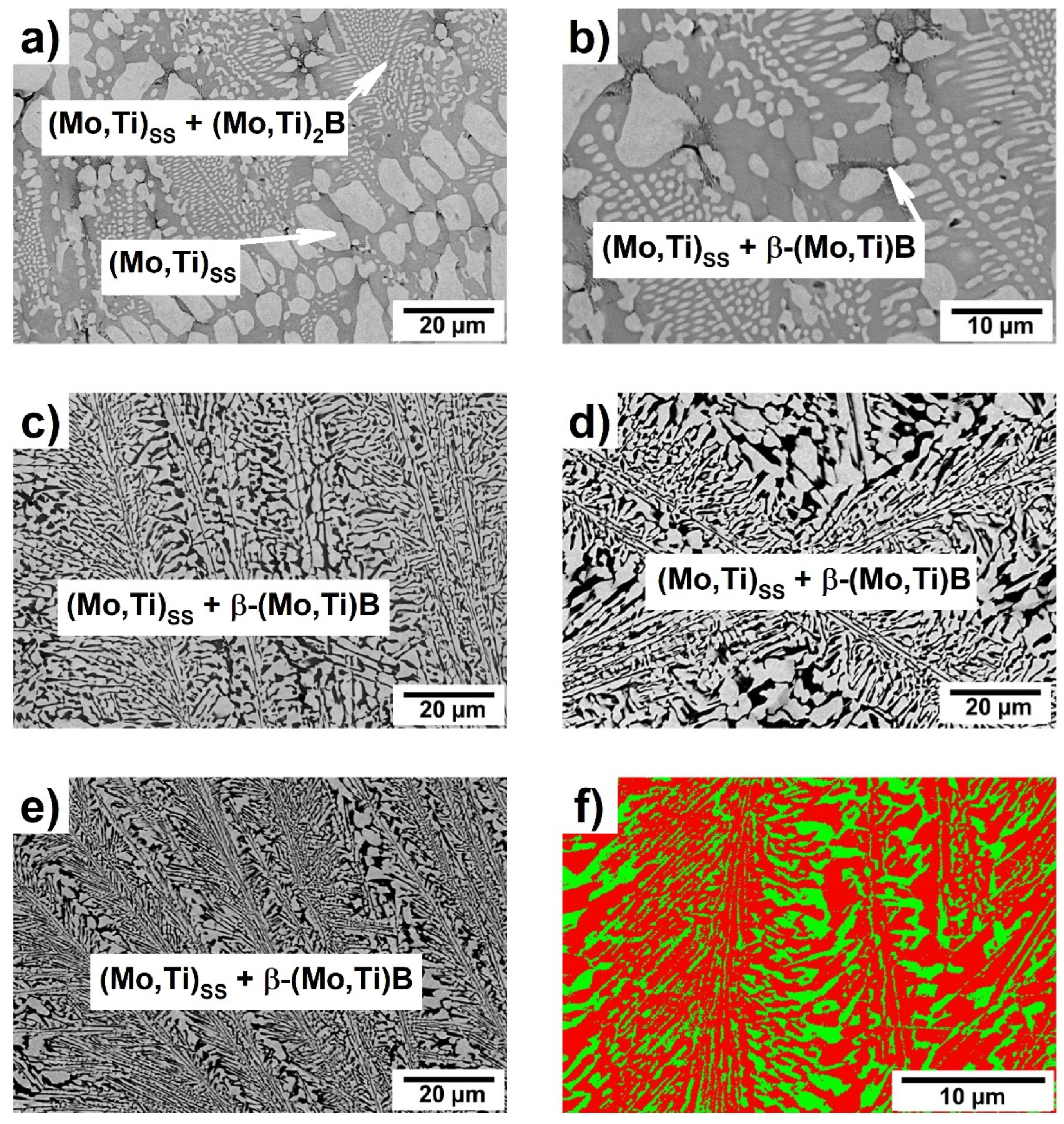
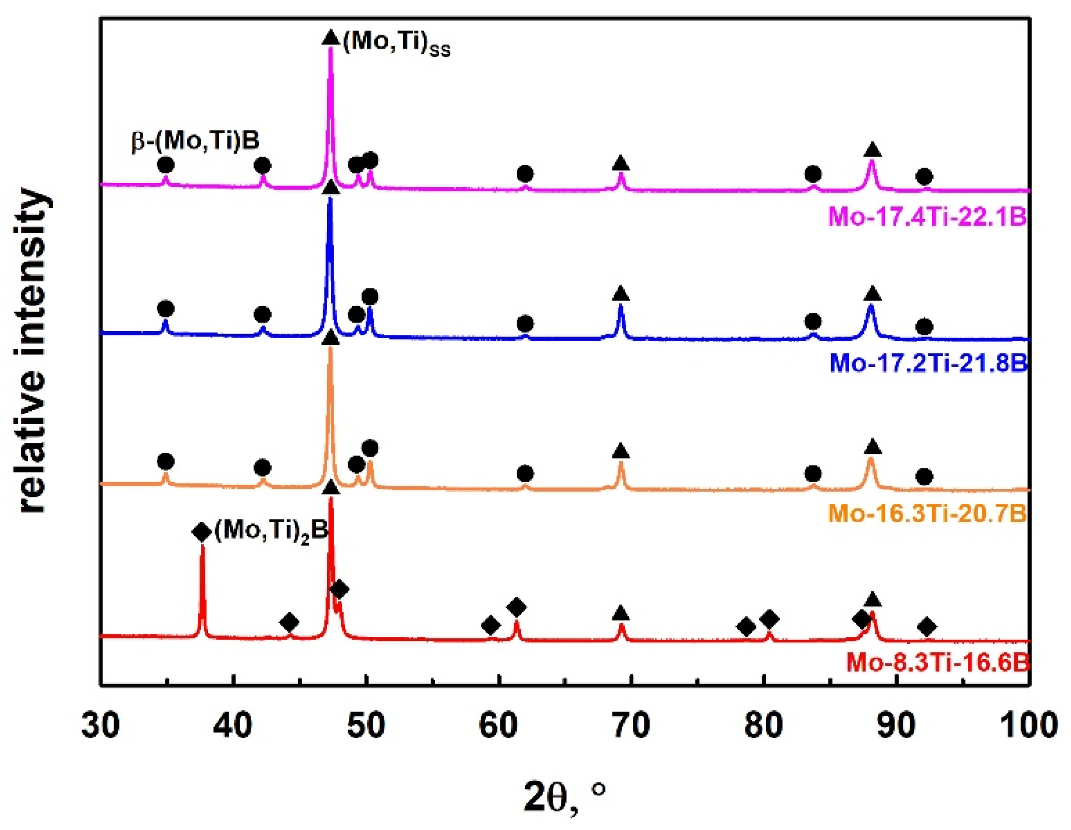
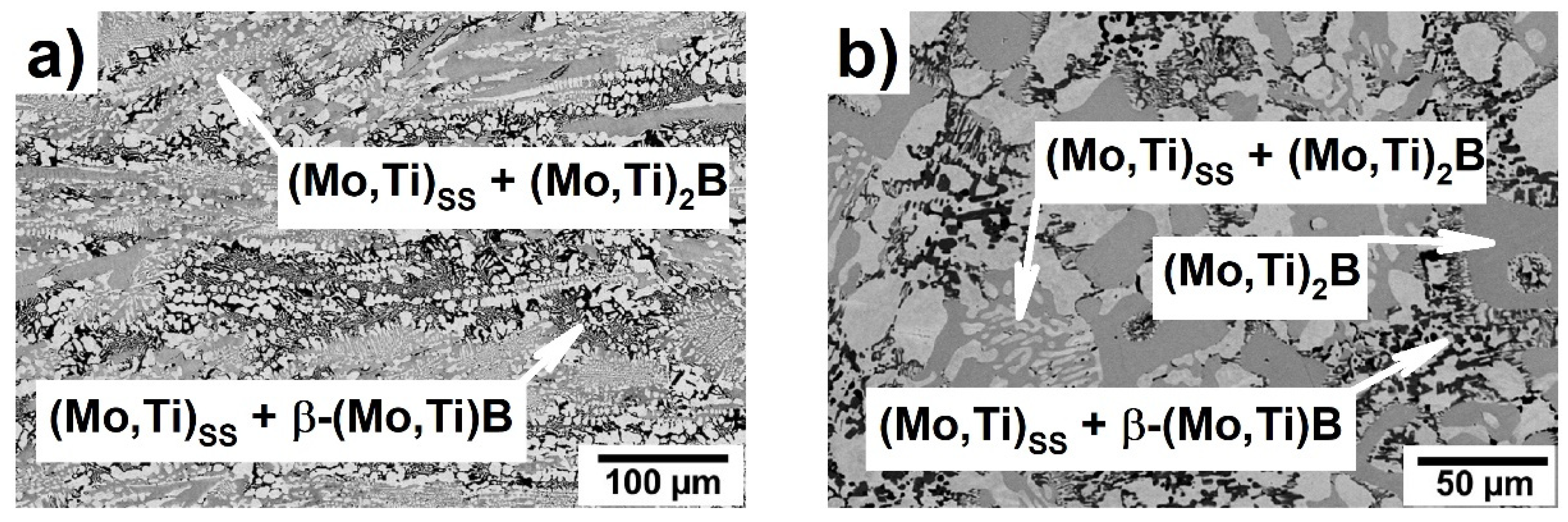
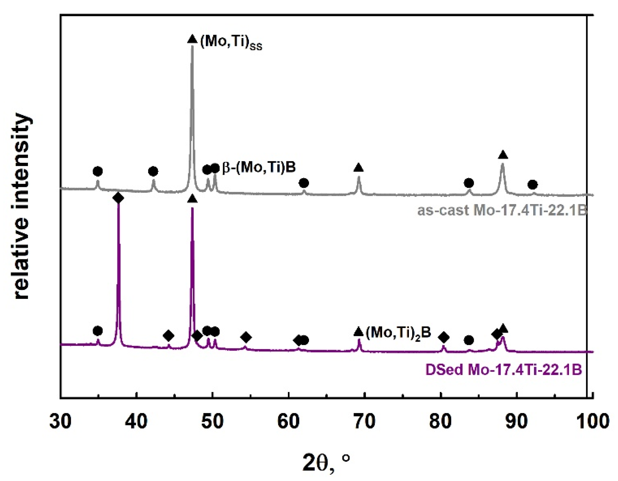
3.1. Microstructure of Mo-Ti-B Alloys after Arc-Melting

SEM-BSE images of the as-cast Mo-Ti-B alloys are presented in Figure 2 and the volume fractions of the single phases are summarized in Table 1.
Figure 2a shows the microstructure of the alloy Mo-8.3Ti-16.6B which represents the Mo-rich corner of the Mo-Ti-B system. The XRD analysis of this alloy is shown in Figure 3 and indicates the existence of the (Mo,Ti)SS and (Mo,Ti)2B phases at high Mo concentrations. The large primary (Mo,Ti)SS dendrites are surrounded by a binary (Mo,Ti)SS-(Mo,Ti)2B eutectic. After the formation of the (Mo,Ti)SS-(Mo,Ti)2B eutectic, β-(Mo,Ti)B begins to form. This can be determined by very small areas of the (Mo,Ti)SS + β-(Mo,Ti)B peritectic at the grain boundaries between (Mo,Ti)SS and (Mo,Ti)2B, as shown in Figure 2b. In this case, the remaining melt and (Mo,Ti)2B form the (Mo,Ti)SS + β-(Mo,Ti)B microstructure in a peritectic manner.
The alloys Mo-16.3Ti-20.7B, Mo-17.2Ti-21.8B and Mo-17.4Ti-22.1B were chosen to study the invariant reaction L + (Mo,Ti)2B ⇄ (Mo,Ti)SS + β-(Mo,Ti)B, marked as “U” in Figure 1. The corresponding microstructures are shown in Figure 2c–e, where the (Mo,Ti)SS appears in light grey and the β-(Mo,Ti)B phase in dark. These phases were also confirmed by X-ray diffraction patterns shown in Figure 3. The solid solution and β-(Mo,Ti)B phases were formed in a peritectic manner and occur in fine lamellar colonies. The alloys Mo-16.3Ti-20.7B and Mo17.2Ti-21.8B are characterized by somewhat coarser peritectics as directly compared with the alloy Mo-17.4Ti-22.1B, respectively. The EBSD phase mapping clearly confirmed the corresponding phases as (Mo,Ti)SS as the matrix phase (shown in red) and β-(Mo,Ti)B with orthorhombic crystal structure (space group: Cmcm), which is depicted in green in Figure 2f). The Mo/Ti ratio in the individual phase are determined around 4 (ca. 80 at.% Mo/20 at.% Ti) in (Mo,Ti)SS, 1.4 (58 at.% Mo/42 at.%Ti) in β-(Mo,Ti)B and 5.5 (ca. 85 at.% Mo/15 at.% Ti) in (Mo,Ti)2B for the as-cast alloys.
It should be considered here that the presented as-cast Mo-Ti-B alloys could be in non-equilibrium in the as-cast state due to comparatively fast solidification in the water-cooled copper mold. The invariant point might be studied in more detail and be validated using a directional solidification (DS) process, which allows one to produce the alloys at slower solidification rates. The alloy composition Mo-17.4Ti-22.1B, which is very close to the U-type reaction (see Figure 1), was chosen for DS and its microstructure will be discussed in the following section.

3.2. Microstructure of the Directionally Solidified Mo-Ti-B Alloy

Figure 4 shows the SEM-BSE image of the microstructure of the DSed Mo-17.4Ti-22.1B alloy in a longitudinal and transverse solidification direction using a growth rate of 70 mm/h. The corresponding XRD plot is shown in Figure 5 and directly compared with the as-cast, non-directionally solidified alloy.
Based on XRD measurements in Figure 5 and SEM image in Figure 4 of the DSed Mo-17.4Ti-22.1B alloy, the (Mo,Ti)SS (~57 vol.%), (Mo,Ti)2B (~20 vol.%) and β-(Mo,Ti)B (~23 vol.%) phases were identified, which differ in the degree of a color intensity (Figure 4). In comparison with the as-cast state, the microstructure of the DSed Mo-17.4Ti-22.1B alloy shows the large primary solidified (Mo,Ti)2B areas, a (Mo,Ti)SS + (Mo,Ti)2B eutectic and the (Mo,Ti)SS + β-(Mo,Ti)B peritectic. The (Mo,Ti)2B phase is surrounded by a binary (Mo,Ti)SS + (Mo,Ti)2B eutectic and the (Mo,Ti)SS + β-(Mo,Ti)B peritectic, which is clearly visible in the Figure 4b). The Mo/Ti ratio in (Mo,Ti)SS, (Mo,Ti)2B and β-(Mo,Ti)B of the DSed alloy does not change compared with the as-cast state alloy.
The difference between the microstructures of the alloy Mo-17.4Ti-22.1B in the as-cast and Dsed state can be explained by their distinct manufacture method (and, thus, different cooling conditions). For instance, prior to the directional solidification process, a pure powder mixture of the respective nominal alloy composition was pressed to a green sample. Thus, the elements might not be distributed homogeneously over the entire green sample [41]. Second, during the DS process the powders undergo a sintering step first, prior to melting and solidification. This will have an influence on the primary phase formation during solidification, if the elements are not homogeneously distributed on an atomic level. However, this (atomic) homogeneity might be expected if a previously melted and thus, pre-alloyed rod is used and re-melted via directional solidification. In this case, the cast microstructure serve as an intrinsic seed and the microstructure can be orientated along the growth direction during the DS process. The procedure used in the present study leads to a DSed microstructure which is comparable to the as-cast one, however, elongated, and oriented along the growth direction. For a comparison we refer to studies performed on ternary eutectic Mo-Si-B alloys processed by either using powder-mixed green samples [42,43] or pre-alloyed casted rods [44,45] during directional solidification.
In addition, the microhardness of alloy Mo-17.4Ti-22.1B was measured and compared between the as-cast and DSed state, Table 2, and will be compared to mechanical properties calculated via DFT in the following section.

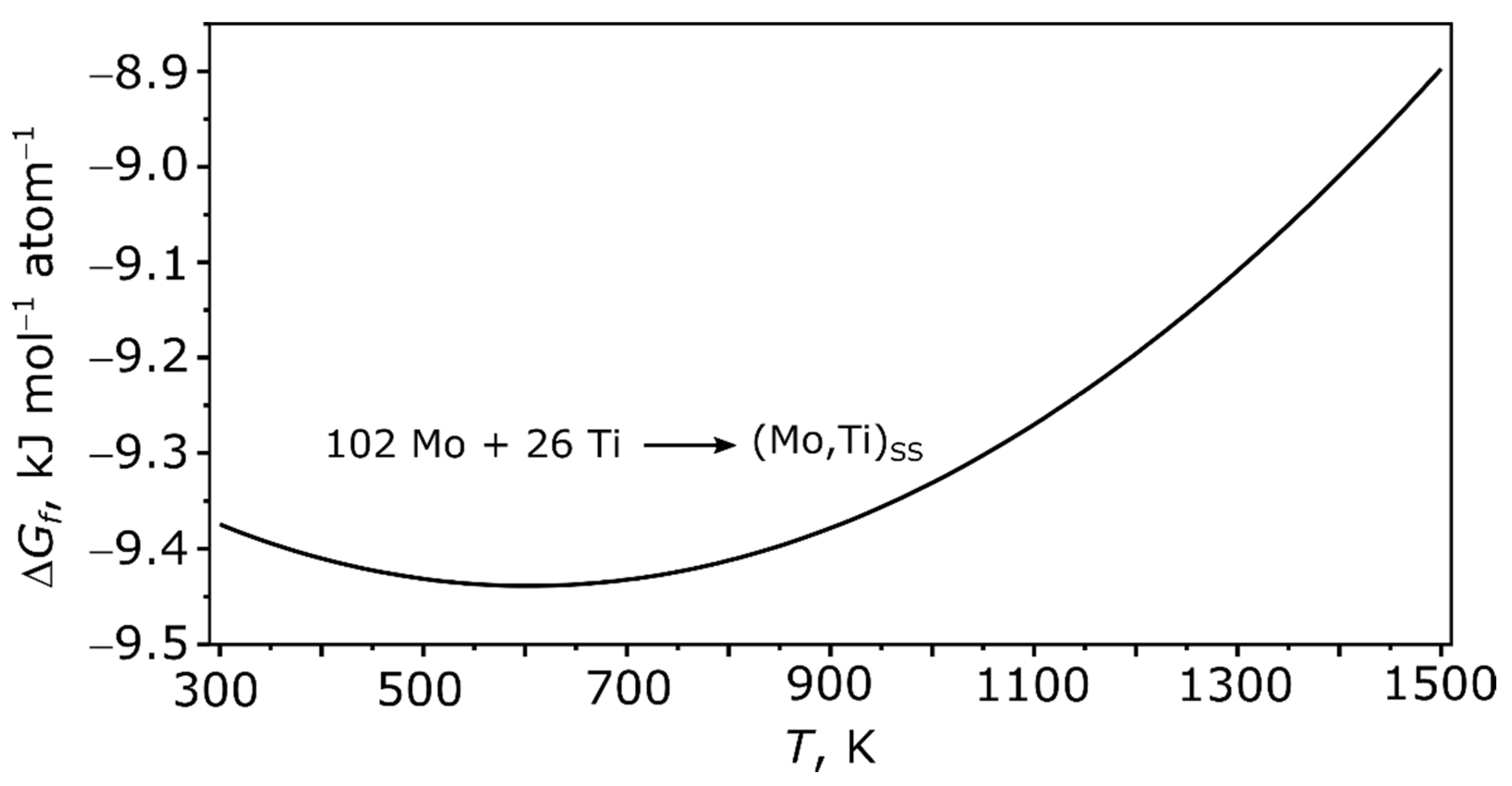
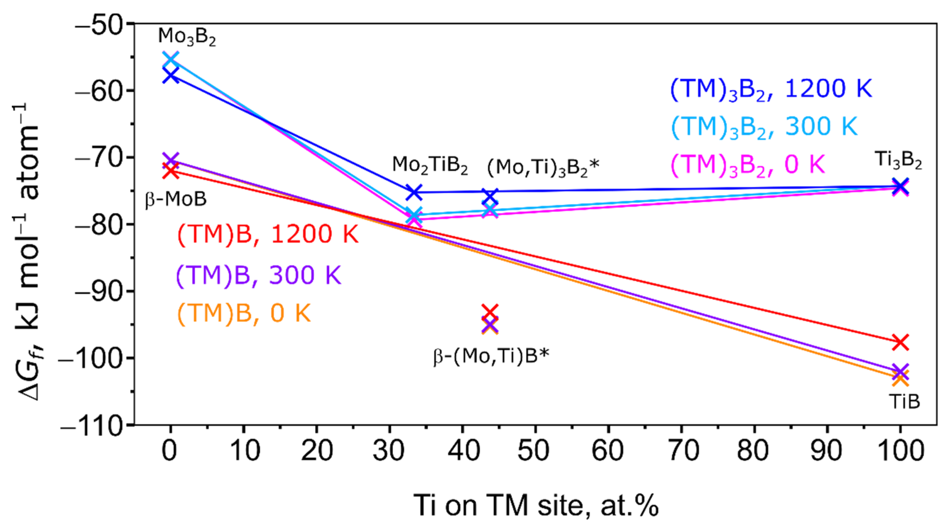
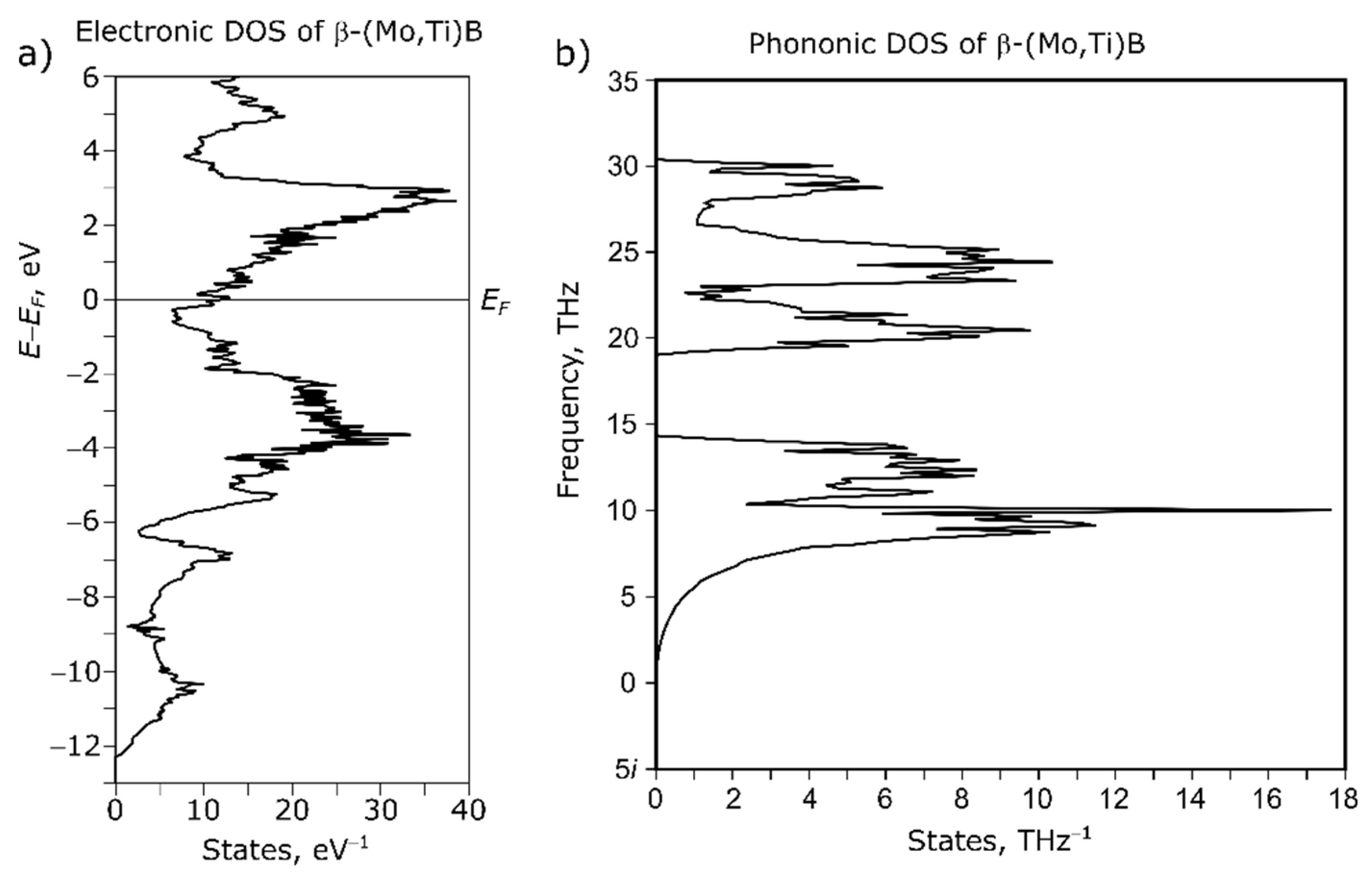
3.3. Results of DFT Calculations

In this paragraph the lattice parameters after the CP2k calculation and the elastic properties of the (Mo,Ti) solid solution and the intermetallics β-(Mo,Ti)B and (Mo,Ti)2B are presented, followed by the Gibbs energies of these compounds and some postulated phases. At the end the electronic and the phononic density-of-states (DOS) of β-(Mo,Ti)B is presented.
In Table 3 the lattice parameters, the elastic moduli and Vickers hardness of the Mo-Ti solid solution and the Mo-Ti intermetallics are shown.
The DFT calculated lattice parameters agree well with those found in experiment. The elastic moduli of the intermetallic compounds are higher than the ones of the solid solution as expected. Compared with the experimental Vickers hardness, the values found with DFT for the (Mo,Ti)SS and (Mo,Ti)2B phase are in excellent agreement (see Table 2).
To provide insight concerning the thermodynamics, the Gibbs energy of formation is calculated for the solid solution and the intermetallic compounds.
In Figure 6, the Gibbs energy of formation of the Mo-Ti solid solution is shown.
The solid solution shows in the temperature range between 300 and 1500 K a negative enthalpy of formation. This means that the solid solution is thermodynamically stable versus its elements at these temperatures. The minimum of the Gibbs energy of formation is at 600 K. In Figure 7 and Figure 8 the Gibbs energy of formation of various Mo-Ti-B intermetallics at 0, 300, and 1200 K is shown.
At all temperatures, the Gibbs energy of formation of the Mo-Ti-B intermetallics is far more negative than the Gibbs energy of formation of the (Mo,Ti)SS. Also it becomes clear that the formation of a β-(Mo,Ti)B type intermetallic is more favored at any temperature and at any amount of Ti than the formation of a “Mo2TiB2” or “Mo2B” type boride. To further investigate the stability of the disordered phases modelled with SQS, solid lines connect the ordered and stoichiometric phases. Energies below that line indicate a special stability, while energies above that line indicate an unstable state. In reference, the addition of Ti to β-MoB highly stabilizes the crystal structure as for 15.63 and 43.75 at.% Ti the Gibbs energy of formation is far below the line connecting the Gibbs energy of formation of β-MoB and TiB at all temperatures. In the case of (Mo,Ti)2B, the disordered Mo1.6875Ti0.3125B is stabilized versus Mo2B and Ti2B but is still less stable than the investigated members of the (Mo,Ti)B series (see Figure 7). As mentioned above, the formation of (Mo,Ti)2B might be due to the relatively small amount of Ti in the intermetallic compared to the other (Mo,Ti) intermetallics in the here investigated alloys. This is a sign that the (Mo,Ti)2B phases are kinetically stable with small amounts of Ti. A different result can be seen for the “Mo2TiB2” type intermetallic in Figure 8. For 43.75 at.% Ti the Gibbs energy of formation is above the line connecting the Gibbs energy of formation of Mo2TiB2 and Ti3B2 at low and medium temperatures. For high temperatures, the Gibbs energy of formation is only slightly below the line indicating only a minor stabilization. All of these findings indicate that at the “as-cast” state the intermetallic compounds in the alloy are kinetically stabilized and similar to the directional solidification with the sample preparation used in this work. A more thermodynamically stable state may be reached with a different DS approach.
According to the electronic DOS of β-(MoTi)B (Figure 9a) the Fermi level EF of the intermetallic compound lies in a very narrow pseudo gap. This indicates only limited flexibility of the chemical composition and only certain amounts of Ti can be dissolved in the intermetallic phase. The phononic DOS of (Figure 9b) shows no occupied imaginary frequencies which points to a dynamically stable crystal structure and thermodynamical stability at low temperatures.
To conclude this paragraph, the Gibbs energy of formation of β-(Mo,Ti)B is at all temperatures lower than the Gibbs energy of formation of the “Mo2TiB2” type intermetallics. The addition of Ti destabilizes the “Mo2TiB2” type intermetallic and hence, cannot be found, while it stabilizes (Mo,Ti)2B as a metastable phase in the as-cast state and after DS. β-(Mo,Ti)B as a thermodynamically stable phase can be found at higher Ti concentration in the as-cast and DSed alloy. These findings explain why β-(Mo,Ti)B is found but no postulated “Mo2TiB2” according to [9].

4. Conclusions

In the present work the microstructure evolution of the different Mo-Ti-B alloys was studied based on SEM-BSE images and XRD analysis. The findings were critically discussed with regard to calculated phase stabilities. The results can be summarized as follows:
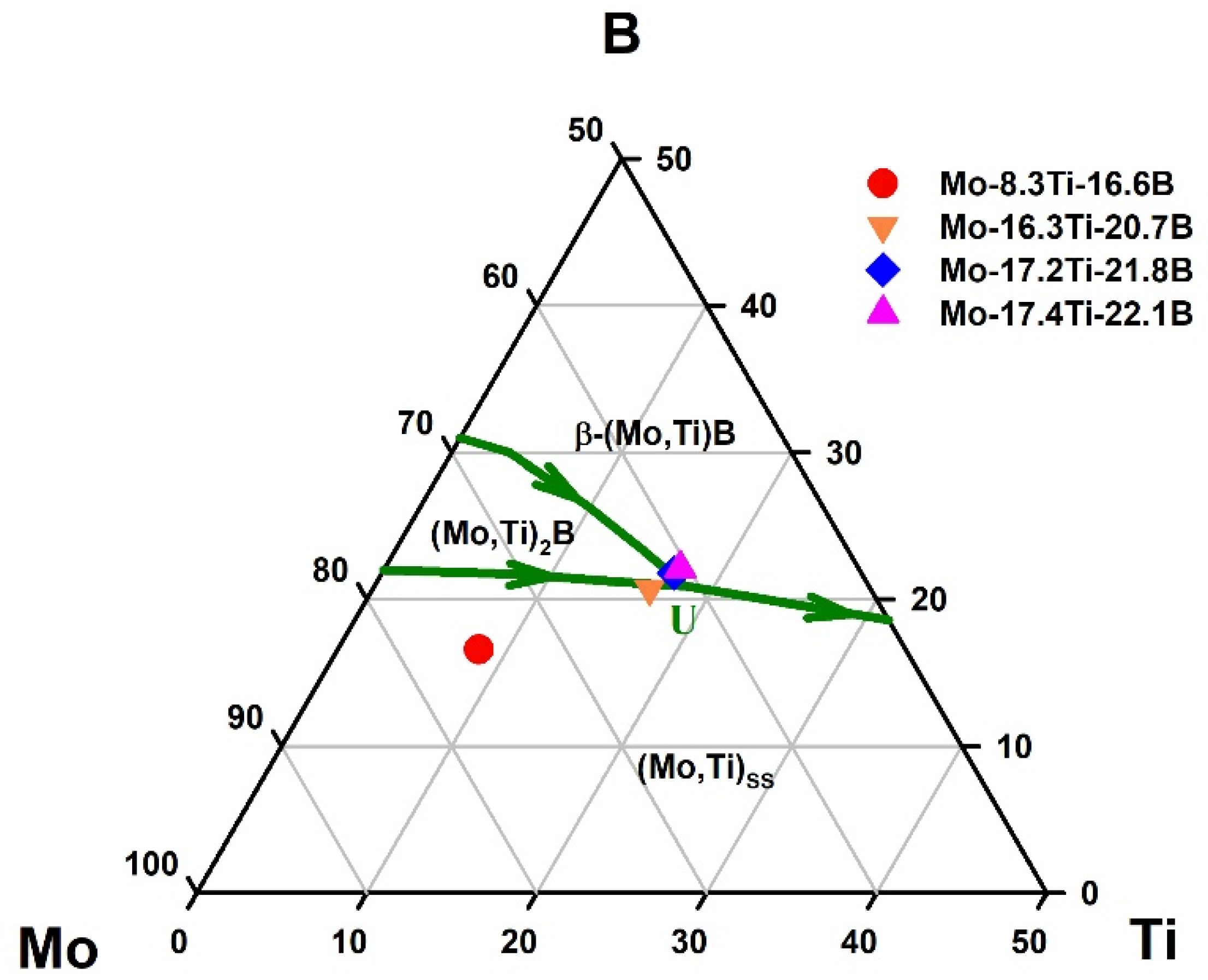
  • Different Mo-Ti-B alloys were investigated by arc-melting to understand their solidification behavior close to the U-type peritectic reaction in the Mo-rich corner of the Mo-Ti-B system.
  • Furthermore, the presence of a ternary phase discussed in the literature should be re-investigated.
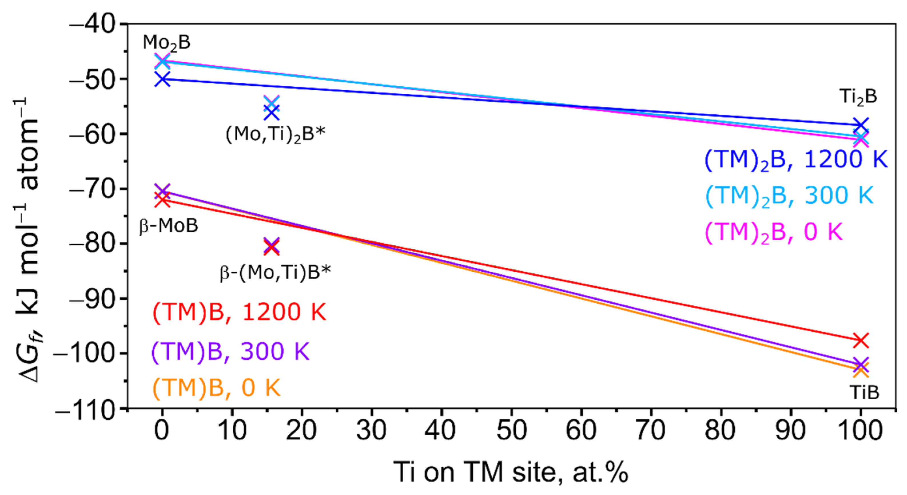
  • Contrary to the literature, a ternary Mo2TiB2 or MoTi2B4 phase, as postulated by Wittmann et al. [9] could not be confirmed, neither by experimental observations nor via DFT calculations.
  • DFT calculations of the Gibbs energies revealed that the known phases (Mo,Ti)SS, (Mo,Ti)2B and β-(Mo,Ti)B are always energetically preferred as no “Mo2TiB2“ is found.
  • As the main result of this study, the Mo2TiB2 phase is believed to be not stable and rather unlikely to exist in the Mo-Ti-B system under the conditions applied in this work.
  • Depending on processing, the microstructures of the peritectic alloy Mo-17.4Ti-22.1 in the as-cast and DSed state differ strongly. A reason is given in the distinct zone melting technique used in this present study and thus, on the different cooling conditions in the as-cast and DSed state.
  • First, mechanical properties were calculated and estimated using the DFT method to combine both experimental and ab-initio approaches for an alloy design step. The trend concerning the expected Vickers hardness of the constituents is in good agreement with the experimental results.

Author Contributions

Conceptualization, V.P., G.H. and R.S.T.; methodology, V.B., G.H., R.S.T. and I.B.; validation, V.P., G.H. and R.S.T.; investigation, V.P, V.B. and R.S.T.; writing—original draft preparation, V.P., G.H. and R.S.T.; writing—review and editing, V.B., I.B. and M.K.; supervision, G.H., V.B., I.B. and M.K. All authors have read and agreed to the published version of the manuscript.

Funding

This research was in part funded by the Federal Ministry of Education and Research (BMBF) within the project “OPOS” (grant number 01DK20072) and the German Research Foundation (DFG) under the grant number 438070774. The support of the Methodisch-Diagnostisches Zentrum Werkstoffprüfung (MDZWP) e.V., Magdeburg, Germany is greatly acknowledged. Open Access funding enabled and organized by Project DEAL.

Institutional Review Board Statement

Not applicable.

Informed Consent Statement

Not applicable.

Data Availability Statement

Not applicable.

Acknowledgments

The authors kindly thank Ulf Betke for supporting the XRD measurements and analysis and Oliver Michael for carrying out the EBSD measurements. R.S.T. also thanks the URZ OVGU Magdeburg for calculation power and time. This paper is dedicated to our colleagues and friends in Ukraine who are threatened and suffering by the war which is contrary to international law.

Conflicts of Interest

The authors declare no conflict of interest. The funders had no role in the design of the study; in the collection, analyses, or interpretation of data; in the writing of the manuscript, or in the decision to publish the results.

References

  1. Perepezko, J.H. The hotter the engine, the better. Science 2009, 326, 1068–1069. [Google Scholar] [CrossRef] [PubMed]
  2. Dimiduk, D.M.; Perepezko, J.H. Mo-Si-B Alloys: Developing a Revolutionary Material. MRS Bull. 2003, 28, 639–645. [Google Scholar] [CrossRef]
  3. Becker, J.; Betke, U.; Wessel, E.; Krüger, M. Alloying effects in Mo-5X (X = Zr, Ti, V)—Microstructural modifications and mechanical properties. Mater. Today Commun. 2018, 15, 314–321. [Google Scholar] [CrossRef]
  4. Schliephake, D.; Azim, M.; Von Klinski-Wetzel, K.; Gorr, B.; Christ, H.J.; Bei, H.; George, E.P.; Heilmaier, M. High-temperature creep and oxidation behavior of Mo-Si-B alloys with high Ti contents. Metall. Mater. Trans. A Phys. Metall. Mater. Sci. 2014, 45, 1102–1111. [Google Scholar] [CrossRef]
  5. Schliephake, D.; Gombola, C.; Kauffmann, A.; Heilmaier, M.; Perepezko, J.H. Enhanced Oxidation Resistance of Mo-Si-B-Ti Alloys by Pack Cementation. Oxid. Met. 2017, 88, 267–277. [Google Scholar] [CrossRef]
  6. Schliephake, D.; Kauffmann, A.; Cong, X.; Gombola, C.; Azim, M.; Gorr, B.; Christ, H.J.; Heilmaier, M. Constitution, oxidation and creep of eutectic and eutectoid Mo-Si-Ti alloys. Intermetallics 2019, 104, 133–142. [Google Scholar] [CrossRef]
  7. Obert, S.; Kauffmann, A.; Heilmaier, M. Characterisation of the oxidation and creep behaviour of novel Mo-Si-Ti alloys. Acta Mater. 2020, 184, 132–142. [Google Scholar] [CrossRef]
  8. Bolbut, V. Development of Mo-Hf-B and Mo-Zr-B Alloys for High-Temperature Application. Ph.D. Thesis, Otto-von-Guericke University Magdeburg, Magdeburg, Germany, 2018. [Google Scholar]
  9. Wittmann, A.; Nowotny, H.; Boller, H. Ein Beitrag zum Dreistoff Titan-Molybdän-Bor. Mon. Chem. 1960, 91, 608–615. [Google Scholar] [CrossRef]
  10. Ordanyan, S.S.; Kosterova, N.V.; Avgustinik, A.I. Phase Equilibria in the System Ti-Mo-B at 1400 °C. Inorg. Mater. 1977, 9, 844–846. (In English) [Google Scholar]
  11. Kovalchenko, M.S.; Samsonov, G.V.; Yasinskaya, G.A. Alloys of the Borides of the Transition Metals with Other Metals. Izv. Akad. Nauk. SSSR 1960, 2, 115–119. [Google Scholar]
  12. Potazhevska, O.A.; Bondar, A.A.; Duma, L.A.; Petyukh, V.M.; Sobolev, V.B.; Velikanova, T.Y. Phase Equilibria in the Melting/Solidification Range of B–Mo–Ti Alloys. Powder Metall. Met. Ceram. 2014, 53, 230–242. [Google Scholar] [CrossRef]
  13. Pirani, M.; Alterthum, H. Über eine Methode zur Schmelzpunktbestimmung an hochschmelzenden Metallen. Z. Elektrochem. Angew. Phys. Chem. 1923, 29, 5–8. [Google Scholar]
  14. Witusiewicz, V.T.; Bondar, A.A.; Hecht, U.; Potazhevska, O.A.; Velikanova, T.Y. Thermodynamic modelling of the ternary B–Mo–Ti system with refined B–Mo description. J. Alloys Compd. 2016, 655, 336–352. [Google Scholar] [CrossRef]
  15. Zhou, D.; Wang, J.; Cui, Q.; Li, Q. Crystal structure and physical properties of Mo 2 B: First-principle calculations. J. Appl. Phys. 2014, 115, 113504. [Google Scholar] [CrossRef]
  16. Zunger, A.; Wei, S.-H.; Ferreira, L.G.; Bernard, J.E. Special quasirandom structures. Phys. Rev. Lett. 1990, 65, 353–356. [Google Scholar] [CrossRef] [PubMed] [Green Version]
  17. Wei, S.-H.; Ferreira, L.G.; Bernard, J.E.; Zunger, A. Electronic properties of random alloys: Special quasirandom structures. Phys. Rev. B 1990, 42, 9622–9649. [Google Scholar] [CrossRef] [Green Version]
  18. Van de Walle, A.; Tiwary, P.; de Jong, M.; Olmsted, D.L.; Asta, M.; Dick, A.; Shin, D.; Wang, Y.; Chen, L.-Q.; Liu, Z.-K. Efficient stochastic generation of special quasirandom structures. Calphad 2013, 42, 13–18. [Google Scholar] [CrossRef]
  19. VandeVondele, J.; Krack, M.; Mohamed, F.; Parrinello, M.; Chassaing, T.; Hutter, J. Quickstep: Fast and accurate density functional calculations using a mixed Gaussian and plane waves approach. Comput. Phys. Commun. 2005, 167, 103–128. [Google Scholar] [CrossRef] [Green Version]
  20. Hutter, J.; Iannuzzi, M.; Schiffmann, F.; VandeVondele, J. Cp2k: Atomistic simulations of condensed matter systems. Wiley Interdiscip. Rev. Comput. Mol. Sci. 2014, 4, 15–25. [Google Scholar] [CrossRef] [Green Version]
  21. Lippert, B.G.; Parrinello, J.H.A.M. A hybrid Gaussian and plane wave density functional scheme. Mol. Phys. 1997, 92, 477–488. [Google Scholar] [CrossRef]
  22. VandeVondele, J.; Hutter, J. Gaussian basis sets for accurate calculations on molecular systems in gas and condensed phases. J. Chem. Phys. 2007, 127, 114105. [Google Scholar] [CrossRef] [PubMed] [Green Version]
  23. Goedecker, S.; Teter, M.; Hutter, J. Separable dual-space Gaussian pseudopotentials. Phys. Rev. B 1996, 54, 1703–1710. [Google Scholar] [CrossRef] [Green Version]
  24. Hartwigsen, C.; Goedecker, S.; Hutter, J. Relativistic separable dual-space Gaussian pseudopotentials from H to Rn. Phys. Rev. B 1998, 58, 3641–3662. [Google Scholar] [CrossRef] [Green Version]
  25. Krack, M. Pseudopotentials for H to Kr optimized for gradient-corrected exchange-correlation functionals. Theor. Chem. Acc. 2005, 114, 145–152. [Google Scholar] [CrossRef] [Green Version]
  26. Perdew, J.P.; Burke, K.; Ernzerhof, M. Generalized Gradient Approximation Made Simple. Phys. Rev. Lett. 1996, 77, 3865–3868. [Google Scholar] [CrossRef] [PubMed] [Green Version]
  27. Togo, A.; Tanaka, I. First principles phonon calculations in materials science. Scr. Mater. 2015, 108, 1–5. [Google Scholar] [CrossRef] [Green Version]
  28. Andersen, O.K.; Skriver, H.L.; Nohl, H.; Johansson, B. Electronic structure of transition metal compounds; ground-state properties of the 3d-monocides in the atomic sphere approximation. Pure Appl. Chem. 1980, 52, 93–118. [Google Scholar] [CrossRef]
  29. Andersen, O.K.; Jepsen, O. Explicit, First-Principles Tight-Binding Theory. Phys. Rev. Lett. 1984, 53, 2571–2574. [Google Scholar] [CrossRef]
  30. Perdew, J.P.; Chevary, J.A.; Vosko, S.H.; Jackson, K.A.; Pederson, M.R.; Singh, D.J.; Fiolhais, C. Atoms, molecules, solids, and surfaces: Applications of the generalized gradient approximation for exchange and correlation. Phys. Rev. B 1992, 46, 6671–6687. [Google Scholar] [CrossRef]
  31. Giannozzi, P.; Andreussi, O.; Brumme, T.; Bunau, O.; Buongiorno Nardelli, M.; Calandra, M.; Car, R.; Cavazzoni, C.; Ceresoli, D.; Cococcioni, M.; et al. Advanced capabilities for materials modelling with Quantum ESPRESSO. J. Phys. Condens. Matter 2017, 29, 465901. [Google Scholar] [CrossRef] [Green Version]
  32. Giannozzi, P.; Baroni, S.; Bonini, N.; Calandra, M.; Car, R.; Cavazzoni, C.; Ceresoli, D.; Chiarotti, G.L.; Cococcioni, M.; Dabo, I.; et al. QUANTUM ESPRESSO: A modular and open-source software project for quantum simulations of materials. J. Phys. Condens. Matter 2009, 21, 395502. [Google Scholar] [CrossRef]
  33. Blöchl, P.E. Projector augmented-wave method. Phys. Rev. B 1994, 50, 17953–17979. [Google Scholar] [CrossRef] [Green Version]
  34. Dal Corso, A. Pseudopotentials periodic table: From H to Pu. Comput. Mater. Sci. 2014, 95, 337–350. [Google Scholar] [CrossRef]
  35. Marzari, N.; Vanderbilt, D.; De Vita, A.; Payne, M.C. Thermal Contraction and Disordering of the Al(110) Surface. Phys. Rev. Lett. 1999, 82, 3296–3299. [Google Scholar] [CrossRef] [Green Version]
  36. Thermo_pw Is an Extension of the Quantum ESPRESSO (QE) Package Which Provides an Alternative Organization of the QE Work-Flow for the Most Common Tasks. Available online: https://dalcorso.github.io/thermo_pw/ (accessed on 1 February 2022).
  37. Voigt, W. Lehrbuch der Kristallphysik; Vieweg+Teubner Verlag: Wiesbaden, Germany, 1966; ISBN 978-3-663-15316-0. [Google Scholar]
  38. Reuss, A. Berechnung der Fließgrenze von Mischkristallen auf Grund der Plastizitätsbedingung für Einkristalle. ZAMM—J. Appl. Math. Mech./Z. Angew. Math. Mech. 1929, 9, 49–58. [Google Scholar] [CrossRef]
  39. Hill, R. The Elastic Behaviour of a Crystalline Aggregate. Proc. Phys. Soc. Sect. A 1952, 65, 349–354. [Google Scholar] [CrossRef]
  40. Tian, Y.; Xu, B.; Zhao, Z. Microscopic theory of hardness and design of novel superhard crystals. Int. J. Refract. Met. Hard Mater. 2012, 33, 93–106. [Google Scholar] [CrossRef]
  41. Loboda, P.I. Zone melting of powder refractory materials. Probl. Spets. Metall. 1999, 2, 59–71. (In Russian) [Google Scholar]
  42. Hasemann, G.; Bogomol, I.; Schliephake, D.; Loboda, P.I.; Krüger, M. Microstructure and creep properties of a near-eutectic directionally solidified multiphase Mo–Si–B alloy. Intermetallics 2014, 48, 28–33. [Google Scholar] [CrossRef]
  43. Hasemann, G.; Kaplunenko, D.; Bogomol, I.; Krüger, M. Near-Eutectic Ternary Mo-Si-B Alloys: Microstructures and Creep Properties. JOM 2016, 68, 2847–2853. [Google Scholar] [CrossRef]
  44. Zhu, L.; Ida, S.; Hasemann, G.; Krüger, M.; Yoshimi, K. Microstructural characterization of arc-melted and directionally solidified near-eutectic molybdenum–silicon–boron alloys. Intermetallics 2021, 132, 107131. [Google Scholar] [CrossRef]
  45. Hasemann, G.; Zhu, L.; Hauschildt, K.; Blankenburg, M.; Ida, S.; Pyczak, F.; Yoshimi, K.; Krüger, M. In situ Observation of Ternary Eutectic Growth in a Directionally Solidified Mo–Si–B Alloy Using High-Energy Synchrotron X-rays. Adv. Eng. Mater. 2021, 23, 2100111. [Google Scholar] [CrossRef]
Figure 1. Liquidus projection of the Mo-Ti-B system, data from [14] superimposed with the alloy compositions of the present study.
Metals 12 00916 g001
Figure 2. SEM-BSE micrograph of the as-cast Mo-Ti-B alloys: (a,b) Mo-8.3Ti-16.6B; (c) Mo-16.3Ti-20.7B; (d) Mo-17.2Ti-21.8B; (e) Mo-17.4Ti-22.1 and (f) EBSD phase map of the as-cast Mo-17.4Ti-22.1B alloy: (Mo,Ti)SS—red; β-(Mo,Ti)B—green (15 kV, step size = 0.088 µm).
Metals 12 00916 g002
Figure 3. XRD patterns of as-cast Mo-Ti-B alloys.
Metals 12 00916 g003
Figure 4. SEM-BSE micrograph of the directionally solidified Mo-17.4Ti-22.1B alloy: (a) longitudinal; (b) transverse.
Metals 12 00916 g004
Figure 5. Comparison of the obtained XRD pattern of Mo-17.4Ti-22.1B in the as-cast and DSed state (longitudinal direction).
Metals 12 00916 g005
Figure 6. Enthalpy of formation of the (Mo,Ti)SS.
Metals 12 00916 g006
Figure 7. Enthalpy of formation of the (TM)B and (TM)2B series at 0, 300, and 1200 K. 0 at.% Ti: β-MoB and Mo2B, 15.63 at.% Ti: SQS cell of (Mo,Ti)2B, 43.75 at.% Ti: SQS cell of β-(Mo,Ti)B, 100 at.% Ti: TiB and Ti2B. Solid lines serve as a guide to distinguish stable (below that line) and unstable (above that line) disordered phases. *: SQS cells.
Metals 12 00916 g007
Figure 8. Enthalpy of formation of the (ΤΜ)B and (TM)3B2 (TM = Mo, Ti) series at 0, 300, and 1200 K. 0 at.% Ti: β-MoB and Mo3B2, 33.3 at.% Ti: Mo2TiB2, 43.75 at.% Ti: SQS cells of β-(Mo,Ti)B and (Mo,Ti)3B2, 100 at.% Ti: TiB and Ti3B2. Solid lines serve as a guide to distinguish stable (below that line) and unstable (above that line) disordered phases. *: SQS cells.
Metals 12 00916 g008
Figure 9. Electronic (a) and phononic (b) density-of-states of β-(Mo,Ti)B.
Metals 12 00916 g009
Table 1. Volume fractions of the present phases in the as-cast Mo-Ti-B alloys in vol.%, determined by Rietvled analysis.
Alloy(Mo,Ti)SS(Mo,Ti)2Bβ-(Mo,Ti)B
Mo-8.3Ti-16.6B8713-
Mo-16.3Ti-20.7B68-32
Mo-17.2Ti-21.8B66-34
Mo-17.4Ti-22.1B65-35
Table 2. Microhardness (HV0.1) of the Mo-Ti-B alloys.
Alloy(Mo,Ti)2B [GPa](Mo,Ti)SS − β-(Mo,Ti)B [GPa]
as-cast Mo-17.4Ti-22.1B-8.7 ± 0.8
DSed Mo-17.4Ti-22.1B18.32 ± 2.27.1 ± 0.6
Table 3. Lattice parameters of the reduced cell (that is the non-supercell): bulk modulus, B; shear modulus, G; Young’s modulus, Y; Vickers hardness, HV of the Mo-Ti solid solution and the intermetallics β-(Mo,Ti)B and (Mo,Ti)2B.
CompoundLattice Parameters [Å]B
[GPa]
G
[GPa]
Y
[GPa]
HV
[GPa]
DFTRietveld (as-Cast)
(Mo,Ti)SSa: 3.1602a: 3.1581229972569
β-(Mo,Ti)Ba: 3.1955a: 3.191127321450931
b: 8.4217b: 8.4181
c: 3.0745c: 3.0709
(Mo,Ti)2Ba: 5.5490a: 5.545327415940018
c: 4.7687c: 4.7566
Publisher’s Note: MDPI stays neutral with regard to jurisdictional claims in published maps and institutional affiliations.

