
Effect of Different Heat Treatments on Tensile Properties and Unnotched and Notched Fatigue Strength of Cold Work Tool Steel Produced by Powder Metallurgy


Abstract
1. Introduction
2. Material and Methods
2.1. Material
2.2. Microstructural Characterization
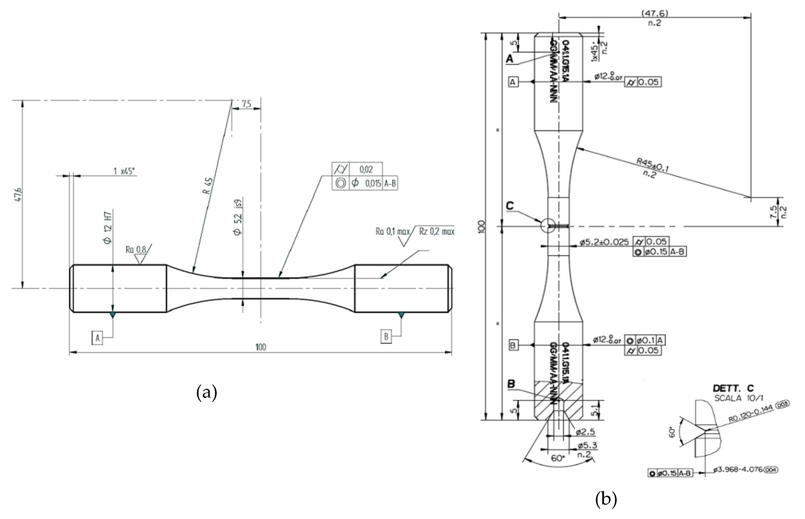
2.3. Mechanical Tests
3. Results
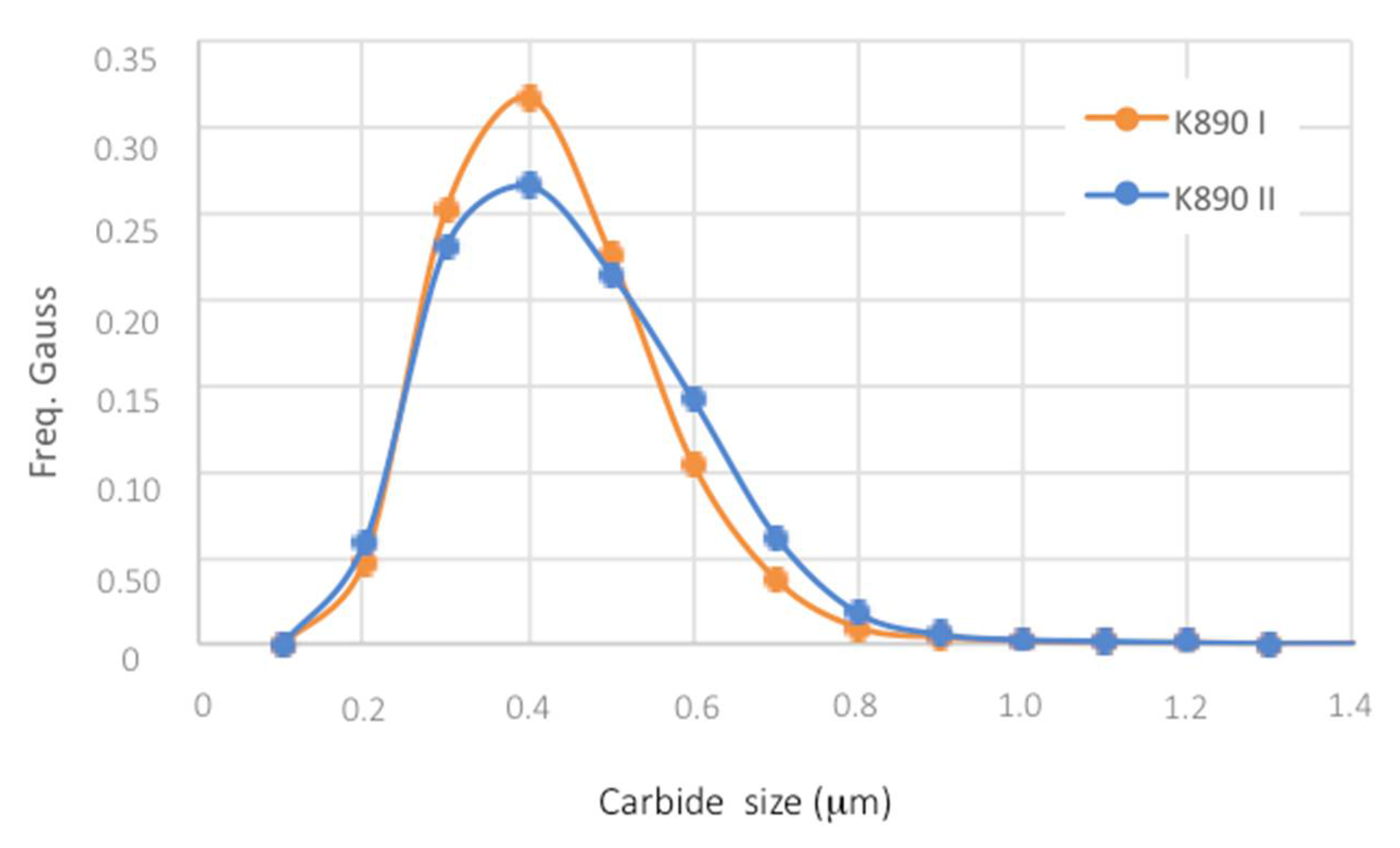
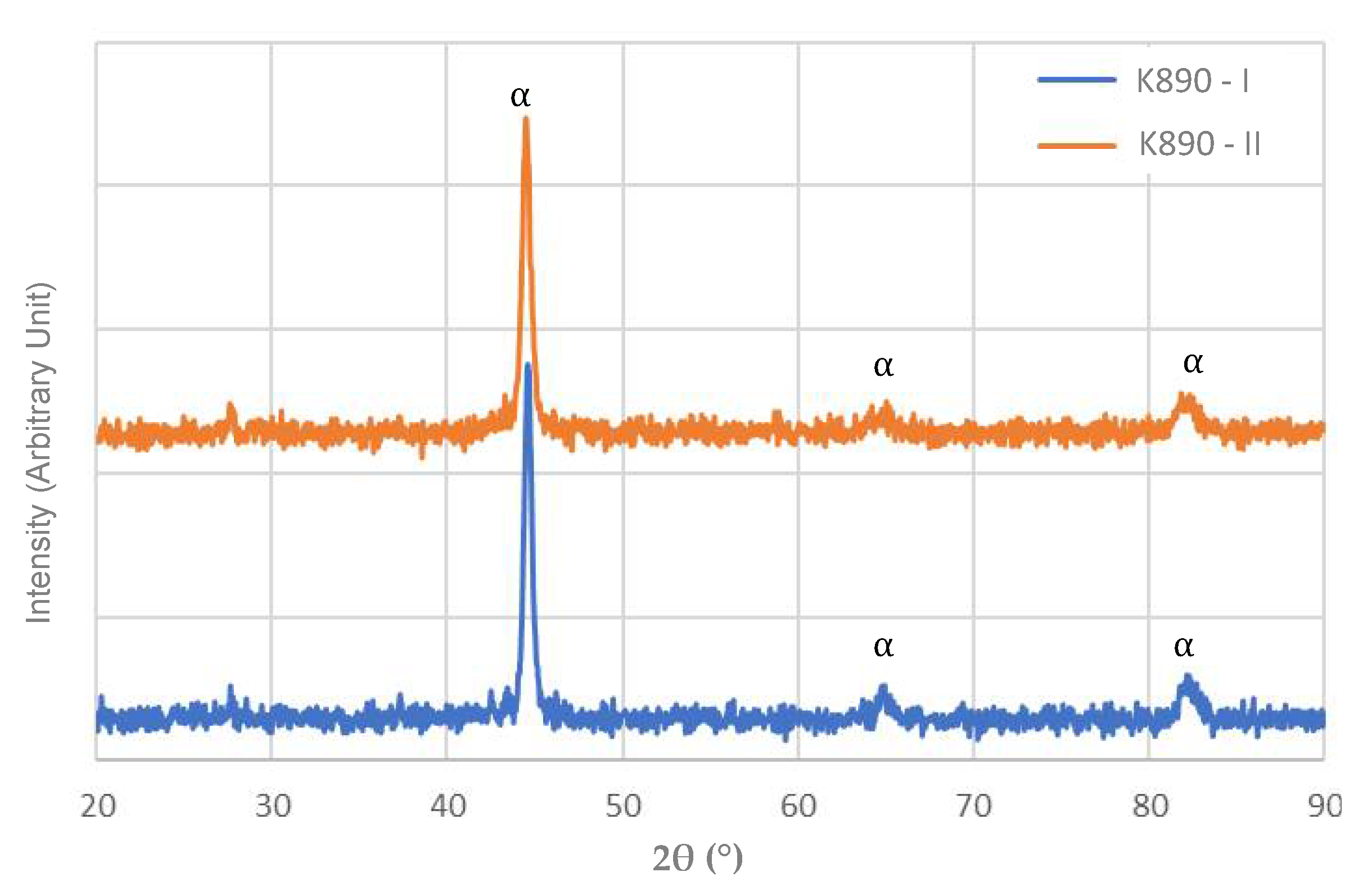
3.1. Microstructure
3.2. Hardness and Tensile Properties
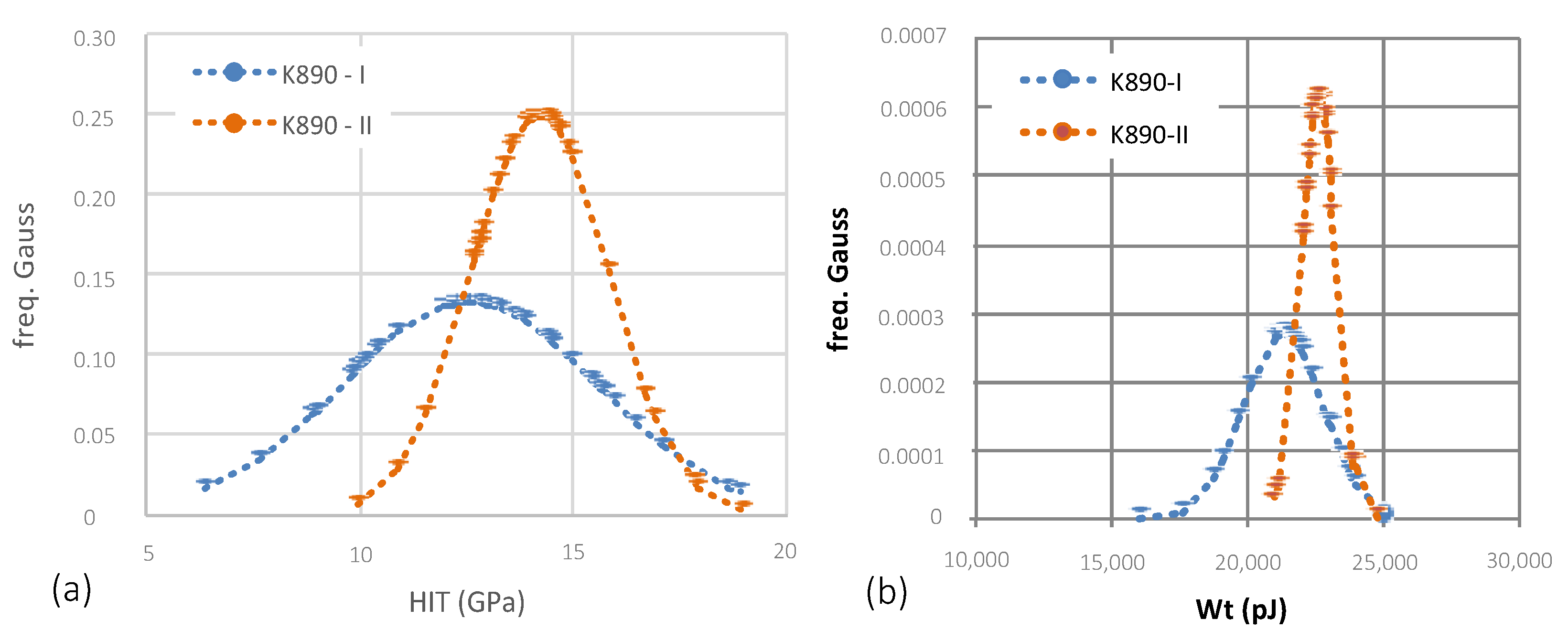
3.3. Nanoindentation
3.4. Fatigue Behaviour
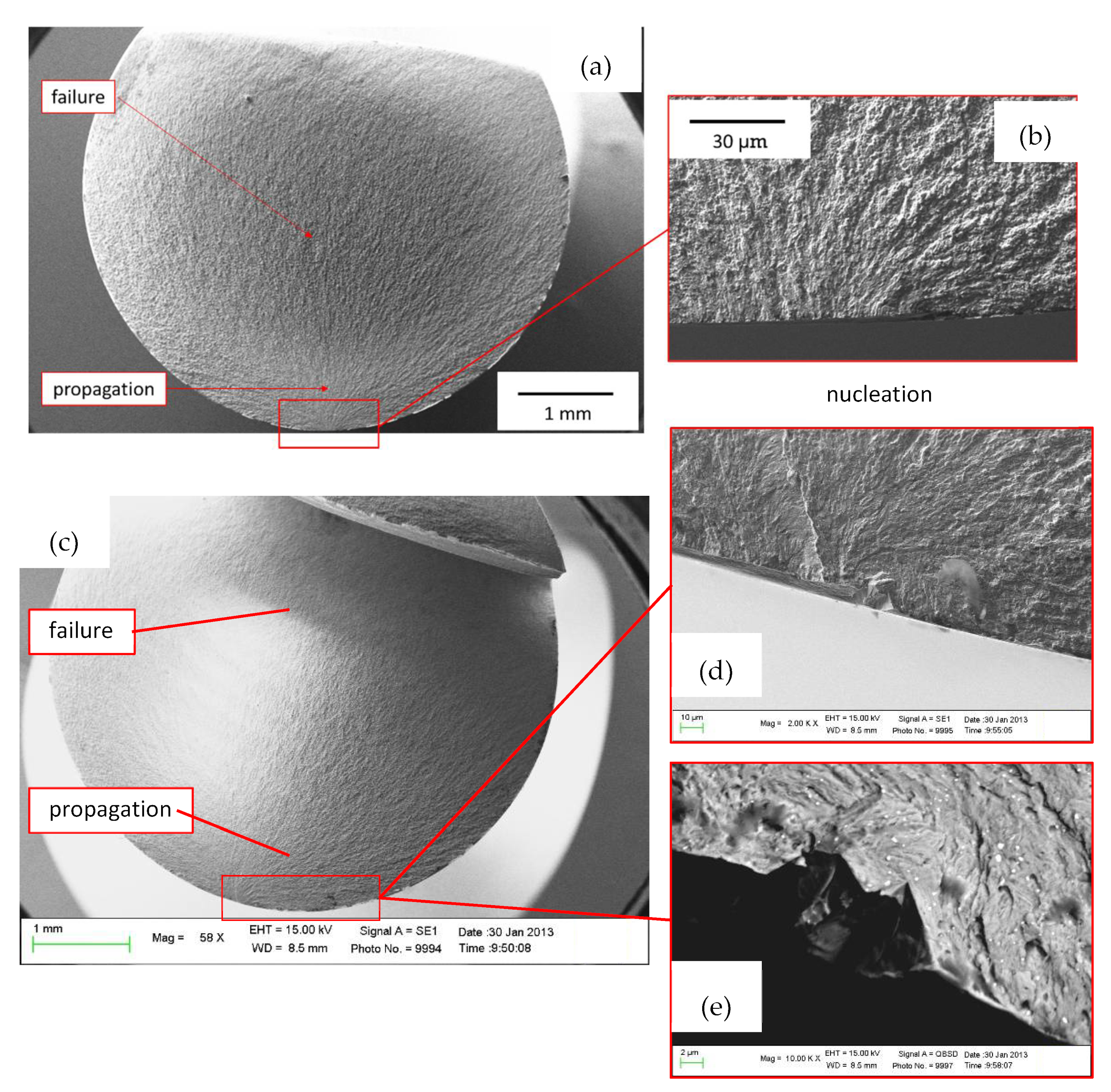
3.5. Fracture Surface Analyses
4. Discussion
5. Conclusions
- The K890-II treatment improved tensile strength without decreasing elongation to failure, probably thanks to both a finer and more homogeneous carbide distribution into the martensite matrix and a decrease in martensite carbon supersaturation.
- Nanoindentation tests confirmed the tensile test data. The K890-II increased Indentation Hardness and indentation work compared to K890-I, which resulted in a reduction in microcracking tendency.
- Compared to the K-890-I treatment, the simultaneous higher strength, ductility and toughness induced by the K890-II treatment led to an increased fatigue strength for both the unnotched and notched specimens. Fatigue strength of the K890-II samples was about 15% and 25% higher for unnotched and notched samples, respectively, in comparison with the K890-I treatment.
- Fracture surface analyses showed that in unnotched specimens the cracks mainly originate from internal inclusions, showing a classical fish-eye morphology, while in the notched ones the cracks mainly develop from the surface.
- This present work demonstrates that the fatigue notch factor Kf of the K890 tool steel, after optimized heat treatment, is comparable with that of high strength steels. This makes K890 steel an highly attractive material for the production of high performance mechanical components, such as crankshafts.
Author Contributions
Funding
Institutional Review Board Statement
Informed Consent Statement
Data Availability Statement
Acknowledgments
Conflicts of Interest
References
- Available online: https://www.bohler-edelstahl.com/en/ (accessed on 7 July 2021).
- Available online: https://www.erasteel.com/ (accessed on 7 July 2021).
- Ceschini, L.; Morri, A.; Morri, A.; Messieri, S. Replacement of Nitrided 33CrMoV Steel with ESR Hot Work Tool Steels for Motorsport Applications: Microstructural and Fatigue Characterization. J. Mater. Eng. Perform. 2018, 27, 3920–3931. [Google Scholar] [CrossRef]
- Beiss, P. Chemical Composition of Powder Metallurgy High-Alloy Tool Steels. In ASM Handbook; Samal, P., Newkirk, J., Eds.; ASM International: Materials Park, OH, USA, 2015; pp. 530–532. [Google Scholar] [CrossRef]
- Schade, C. Introduction to Metal Powder Production and Characterization. In ASM Handbook; ASM International: Materials Park, OH, USA, 2015; pp. 55–57. [Google Scholar] [CrossRef]
- Mashl, S.J. Powder Metallurgy Processing by Hot Isostatic Pressing. In ASM Handbook; ASM International: Materials Park, OH, USA, 2015; pp. 260–270. [Google Scholar] [CrossRef]
- Garrison, W.M., Jr. Ultrahigh-strength steels for aerospace applications. JOM 1990, 42, 20–24. [Google Scholar] [CrossRef]
- Meurling, F.; Melander, A.; Tidesten, M.; Westin, L. Influence of carbide and inclusion contents on the fatigue properties of high speed steels and tool steels. Int. J. Fatigue 2001, 23, 215–224. [Google Scholar] [CrossRef]
- Melander, A.; Rolfsson, M.; Nordgren, A.; Jansson, B.; Hedberg, H.; Lund, T. Influence of inclusion contents on fatigue proper-ties of SAE 52100 bearing steels. Scand. J. Metall. 1991, 20, 229–244. [Google Scholar]
- Shiozawa, K.; Morii, Y.; Nishino, S.; Lu, L. Subsurface crack initiation and propagation mechanism in high-strength steel in a very high cycle fatigue regime. Int. J. Fatigue 2006, 28, 1521–1532. [Google Scholar] [CrossRef]
- Sohar, C.; Betzwar-Kotas, A.; Gierl, C.; Weiss, B.; Danninger, H. Gigacycle fatigue behavior of a high chromium alloyed cold work tool steel. Int. J. Fatigue 2008, 30, 1137–1149. [Google Scholar] [CrossRef]
- Sohar, C.R.; Betzwar-Kotas, A.; Gierl, C.; Weiss, B.; Danninger, H. Fractographic evaluation of gigacycle fatigue crack nucleation and propagation of a high Cr alloyed cold work tool steel. Int. J. Fatigue 2008, 30, 2191–2199. [Google Scholar] [CrossRef]
- Chapetti, M.D.; Tagawa, T.; Miyata, T. Ultra-long cycle fatigue of high-strength carbon steels part I: Review and analysis of the mechanism of failure. Mater. Sci. Eng. A 2003, 356, 227–235. [Google Scholar] [CrossRef]
- Krewerth, D.; Lippmann, T.; Weidner, A.; Biermann, H. Influence of non-metallic inclusions on fatigue life in the very high cycle fatigue regime. Int. J. Fatigue 2016, 84, 40–52. [Google Scholar] [CrossRef]
- Li, W.; Deng, H.; Liu, P. Interior Fracture Mechanism Analysis and Fatigue Life Prediction of Surface-Hardened Gear Steel under Axial Loading. Materials 2016, 9, 843. [Google Scholar] [CrossRef]
- Torres, Y.; Rodríguez, S.; Mateo, A.; Anglada, M.; Llanes, L. Fatigue behavior of powder metallurgy high-speed steels: Fatigue limit prediction using a crack growth threshold-based approach. Mater. Sci. Eng. A 2004, 387–389, 501–504. [Google Scholar] [CrossRef]
- Fernandez, A.; Pautler, S.E. Metal Fatigue—Effects of Small Defects and Nonmetallic Inclusions. JSLS J. Soc. Laparoendosc. Surg. 2011, 15, 421–423. [Google Scholar] [CrossRef] [PubMed][Green Version]
- Fukaura, K.; Yokoyama, Y.; Yokoi, D.; Tsujii, N.; Ono, K. Fatigue of cold-work tool steels: Effect of heat treatment and carbide morphology on fatigue crack formation, life, and fracture surface observations. Metall. Mater. Trans. A 2004, 35, 1289–1300. [Google Scholar] [CrossRef]
- Verdiere, A.; Cerda, F.C.; Llanes, A.B.; Wu, J.; Crebolder, L.; Petrov, R. Effect of the austenitizing parameters on the microstructure and mechanical properties of 75Cr1 tool steel. Mater. Sci. Eng. A 2020, 785, 139331. [Google Scholar] [CrossRef]
- Leskovšek, V.; Šuštaršič, B.; Jutriša, G. The influence of austenitizing and tempering temperature on the hardness and fracture toughness of hot-worked H11 tool steel. J. Mater. Process. Technol. 2006, 178, 328–334. [Google Scholar] [CrossRef]
- Ali, M.; Porter, D.; Kömi, J.; Eissa, M.; El Faramawy, H.; Mattar, T. The effect of double austenitization and quenching on the microstructure and mechanical properties of CrNiMoWMnV ultrahigh-strength steels after low-temperature tempering. Mater. Sci. Eng. A 2019, 763, 138169. [Google Scholar] [CrossRef]
- Patil, N.; Kakkeri, S. Sangamesh. Effect of Cryogenic Treated and Untreated Tool on its Tool Life-Review. Int. J. Sci. Res. 2014, 3, 141–145. [Google Scholar]
- Pellizzari, M.; Molinari, A.; Gialanella, S.; Straffelini, G. Effect of deep cryogenic treatment on the microstructural properties of AISI H13 steel. Metall. Ital. 2001, 93, 21–27. [Google Scholar]
- Sola, R.; Veronesi, P.; Giovanardi, R.; Forti, A.; Parigi, G. Effect of heat treatment before cryogenic cooling on the proprieties of AISI M2 steel. Metall. Ital. 2017, 109, 5–16. [Google Scholar]
- Molinari, A.; Pellizzari, M.; Gialanella, S.; Straffelini, G.; Stiasny, K. Effect of deep cryogenic treatment on the mechanical properties of tool steels. J. Mater. Process. Technol. 2001, 118, 350–355. [Google Scholar] [CrossRef]
- Pérez, M.; Belzunce, F.J. The effect of deep cryogenic treatments on the mechanical properties of an AISI H13 steel. Mater. Sci. Eng. A 2015, 624, 32–40. [Google Scholar] [CrossRef]
- Sonar, T.; Lomte, S.; Gogte, C. Cryogenic Treatment of Metal—A Review. Mater. Today: Proc. 2018, 5, 25219–25228. [Google Scholar] [CrossRef]
- Das, D.; Dutta, A.K.; Ray, K.K. Sub-zero treatments of AISI D2 steel: Part II. Wear behavior. Mater. Sci. Eng. A 2010, 527, 2194–2206. [Google Scholar] [CrossRef]
- Das, D.; Sarkar, R.; Dutta, A.; Ray, K.K. Influence of sub-zero treatments on fracture toughness of AISI D2 steel. Mater. Sci. Eng. A 2010, 528, 589–603. [Google Scholar] [CrossRef]
- Niaki, K.S.; Vahdat, S.E. Fatigue Scatter of 1.2542 Tool Steel after Deep Cryogenic Treatment. Mater. Today: Proc. 2015, 2, 1210–1215. [Google Scholar] [CrossRef]
- Vahdat, S.E.; Nategh, S.; Mirdamadi, S. Microstructure and tensile properties of 45WCrV7 tool steel after deep cryogenic treatment. Mater. Sci. Eng. A 2013, 585, 444–454. [Google Scholar] [CrossRef]
- Shinde, T.; Dhokey, N.B. Influence of Tertiary Carbides on Improving Fatigue Limit of H13 Die Steels. Met. Microstruct. Anal. 2017, 6, 398–406. [Google Scholar] [CrossRef]
- Sola, R.; Giovanardi, R.; Parigi, G.; Veronesi, P. A Novel Methods for Fracture Toughness Evaluation of Tool Steels with Post-Tempering Cryogenic Treatment. Metals 2017, 7, 75. [Google Scholar] [CrossRef]
- Collins, D.N. Deep Gryogenic Treatment of Tool Steels: A Review. Heat Treat. Met. 1996, 2, 40–42. [Google Scholar]
- Pellizzari, M.; Molinari, A.; Girardini, L.; Maldarelli, L. Deep cryogenic treatment of AISI M2 high-speed steel. Int. J. Microstruct. Mater. Prop. 2008, 3, 383. [Google Scholar] [CrossRef]
- Gonçalves, V.R.M.; Podgornik, B.; Leskovšek, V.; Totten, G.E.; Canale, L.D.C.F. Influence of Deep Cryogenic Treatment on the Mechanical Properties of Spring Steels. J. Mater. Eng. Perform. 2019, 28, 769–775. [Google Scholar] [CrossRef]
- Available online: https://www.bohler-edelstahl.com/en/products/k890/ (accessed on 6 July 2021).
- ISO 14707:2021; Surface Chemical Analysis—Glow Discharge Optical Emission Spectrometry (GD-OES)—Introduction to Use. International Organization for Standardization: Geneva, Switzerland, 2021.
- ASTM E3-11; Standard Guide for Preparation of Metallographic Specimens. ASTM International: West Conshohocken, PA, USA, 2017.
- ASTM E407-07; Standard Practice for Microetching Metals and Alloys. ASTM International: West Conshohocken, PA, USA, 2015.
- ASTM E975-13; Standard Practice for X-ray Determination of Retained Austenite in Steel with Near Random Crystallo-Graphic Orientation. ASTM International: West Conshohocken, PA, USA, 2013.
- ISO 14577-1:2015; Metallic Materials—Instrumented Indentation Test for Hardness and Materials Parameters—Part 1: Test Method. International Organization for Standardization: Geneva, Switzerland, 2015.
- Sola, R.; Veronesi, P.; Giovanardi, R.; Parigi, G. A Novel Duplex Treatment of C20 Steel Combining Low-Pressure Carburizing and Laser Quenching. J. Mater. Eng. Perform. 2017, 26, 5396–5403. [Google Scholar] [CrossRef]
- Sola, R.; Poli, G.; Veronesi, P.; Giovanardi, R. Effects of Surface Morphology on the Wear and Corrosion Resistance of Post-Treated Nitrided and Nitrocarburized 42CrMo4 Steel. Met. Mater. Trans. A 2014, 45, 2827–2833. [Google Scholar] [CrossRef]
- ISO 6507-1:2018; Metallic materials—Vickers hardness test—Part 1: Test method. International Organization for Standardization: Geneva, Switzerland, 2018.
- ISO 6892-1:2019; Metallic materials—Tensile testing—Part 1: Method of test at room temperature. International Organization for Standardization: Geneva, Switzerland, 2019.
- ISO 1143:2010; Metallic Materials—Rotating bar Bending Fatigue Testing. International Organization for Standardization: Geneva, Switzerland, 2010.
- Noda, N.-A.; Takase, Y. Stress concentration formula useful for all notch shape in a round bar (comparison between torsion, tension and bending). Int. J. Fatigue 2006, 28, 151–163. [Google Scholar] [CrossRef]
- Young, W.C.; Budynas, R.G. Roark’s Formulas for Stress and Strain, 7th ed.; McGraw Hill: New York, NY, USA, 2002. [Google Scholar]
- ISO 12107:2012; Metallic Materials—Fatigue Testing—Statistical Planning and Analysis of Data. International Organization for Standardization: Geneva, Switzerland, 2012.
- DIN 4768; Determination of values of surface roughness parameters Ra. Rz, Rmax using electrical contact (stylus) instruments Concepts and measuring conditions. Deutsches Institut für Normung e. V.: Berlin, Germany, 1990.
- Totten, G.E. Steel Heat Treatment, 1st ed.; CRC Press: Boca Raton, FL, USA, 2006; ISBN 9780849384530. [Google Scholar]
- Totten, G.E. Steel Heat Treating Fundamentals and Processes. In ASM Handbook; ASM International: Materials Park, Geauga County, OH, USA, 2013; Volume 4A. [Google Scholar]
- Balijepalli, S.; Donnini, R.; Kaciulis, S.; Montanari, R.; Varone, A. Young’s Modulus Profile in Kolsterized AISI 316L Steel. Mater. Sci. Forum 2013, 762, 183–188. [Google Scholar] [CrossRef]
- Balijepalli, S.K.; Colantoni, I.; Donnini, R.; Kaciulis, S.; Lucci, M.; Montanari, R.; Ucciardello, N.; Varone, A. Modulo elastico della fase S in un acciaio 316 L kolsterizzato. Metall. Ital. 2013, 1, 42–47. [Google Scholar]
- Mao, K.S.; Sun, C.; Huang, Y.; Shiau, C.-H.; Garner, F.A.; Freyer, P.D.; Wharry, J.P. Grain orientation dependence of nanoindentation and deformation-induced martensitic phase transformation in neutron irradiated AISI 304L stainless steel. Materialia 2019, 5, 100208. [Google Scholar] [CrossRef]
- Yen, C.S.; Dolan, T.J. A Critical Review of the Criteria for Notch-Sensitivity in Fatigue of Metals; University of Illinois Bulletin: Urbana, OH, USA, 2007. [Google Scholar]
- Kazymyrovych, V.; Bergström, J.; Burman, C. The Significance of Crack Initiation Stage in Very High Cycle Fatigue of Steels. Steel Res. Int. 2010, 81, 308–314. [Google Scholar] [CrossRef]
- Murakami, Y. Metal Fatigue: Effects of Small Defects and Non-Metallic Inclusions; Elsevier: Amsterdam, The Netherlands, 2002. [Google Scholar]
- Ghanem, F.; Braham, C.; Fitzpatrick, M.E.; Sidhom, H. Effect of Near-Surface Residual Stress and Microstructure Modification from Machining on the Fatigue Endurance of a Tool Steel. J. Mater. Eng. Perform. 2002, 11, 631–639. [Google Scholar] [CrossRef]
- Shimatani, Y.; Shiozawa, K.; Nakada, T.; Yoshimoto, T.; Lu, L. The effect of the residual stresses generated by surface finishing methods on the very high cycle fatigue behavior of matrix HSS. Int. J. Fatigue 2011, 33, 122–131. [Google Scholar] [CrossRef]
- Akiniwa, Y.; Miyamoto, N.; Tsuru, H.; Tanaka, K. Notch effect on fatigue strength reduction of bearing steel in the very high cycle regime. Int. J. Fatigue 2006, 28, 1555–1565. [Google Scholar] [CrossRef]
- Das, D.; Dutta, A.; Ray, K. Correlation of microstructure with wear behaviour of deep cryogenically treated AISI D2 steel. Wear 2009, 267, 1371–1380. [Google Scholar] [CrossRef]
- Çakir, F.H.; Çelik, O.N. The effects of cryogenic treatment on the toughness and tribological behaviors of eutectoid steel. J. Mech. Sci. Technol. 2017, 31, 3233–3239. [Google Scholar] [CrossRef]
- Huang, J.; Zhu, Y.; Liao, X.; Beyerlein, I.; Bourke, M.; Mitchell, T. Microstructure of cryogenic treated M2 tool steel. Mater. Sci. Eng. A 2003, 339, 241–244. [Google Scholar] [CrossRef]
- Gavriljuk, V.; Theisen, W.; Sirosh, V.; Polshin, E.; Kortmann, A.; Mogilny, G.; Petrov, Y.N.; Tarusin, Y.V. Low-temperature martensitic transformation in tool steels in relation to their deep cryogenic treatment. Acta Mater. 2013, 61, 1705–1715. [Google Scholar] [CrossRef]
- Senthilkumar, D.; Rajendran, I.; Pellizzari, M.; Siiriainen, J. Influence of shallow and deep cryogenic treatment on the residual state of stress of 4140 steel. J. Mater. Process. Technol. 2011, 211, 396–401. [Google Scholar] [CrossRef]
- Budynas, R.; Nisbett, K. Shigley’s Mechanical Engineering Design, 10th ed.; McGraw-Hill: New York, NY, USA, 2015. [Google Scholar]
- Kuhn, P.; Hardraht, H.F. An Engineering Method for Estimating the Notch-Size Effect in Fatigue Test on Steel; Technical Note (TN) 2805; National Advisory Committee for Aeronautics (NACA): Washington, DC, USA, 1952. [Google Scholar]
- Hu, Z.-Z.; Cao, S.-Z. Relationship between fatigue notch factor and strength. Eng. Fract. Mech. 1994, 48, 127–136. [Google Scholar] [CrossRef]
- Neuber, H. Theory of Notch Stresses: Principles for Exact Calculation of Strength with Reference to Structural Form And material; United States Atomic Energy Commission (USAEC) Office of Technical Services: Oak Ridge, TN, USA, 1961. [Google Scholar]
- Peterson, R.E. Stress Concentration Factors; John Wiley: New York, NY, USA, 1974. [Google Scholar]
- Heywood, R.B. Designing against Fatigue; Chapmann and Hall: London, UK, 1962. [Google Scholar]
- Hu, Z.Z.; Cao, S.Z. Relation Between strain-hardening exponent and strength. J. Wan Jiaotong Univ. 1993, 27, 71–76. [Google Scholar]


| C | Mn | Si | Ni | Co | Mo | V | W | Fe |
|---|---|---|---|---|---|---|---|---|
| 0.80 ± 0.02 | 0.35 ± 0.01 | 0.59 ± 0.01 | 4.14 ± 0.04 | 3.90 ± 0.02 | 2.99 ± 0.01 | 2.30 ± 0.03 | 2.43 ± 0.01 | Bal. |
| HV30 | YS (MPa) | UTS (MPa) | A% (%) | |
|---|---|---|---|---|
| K890-I | 741 ± 3 | 2153 ± 20 | 2513 ± 10 | 2.1 ± 0.1 |
| K890-II | 817 ± 17 | 2381 ± 15 | 2848 ± 22 | 2.3 ± 0.1 |
| HI (GPa) | Wt (pJ) | Wp (pJ) | |
|---|---|---|---|
| K890-I | 12.5 ± 1 | 21,400 ± 875 | 15,171 ± 135 |
| K890-II | 14.4 ± 2 | 22,268 ± 220 | 16,635 ± 160 |
| K890-I | 3 | 1186 ± 29 | 525 ± 26 | 2.25 | 0.47 |
| K890-II | 3 | 1314 ± 39 | 692 ± 31 | 1.9 | 0.46 |
| Peterson (Empirical) | Heywood (Empirical) | Hu and Cao (Empirical for Low Notch Sensitivity Materials) | Experimental | |
|---|---|---|---|---|
| K890-I | Kf=2.8 | Kf=2.6 | Kf=2.0 | Kf = 2.2 |
| K890-II | Kf = 1.9 |
Publisher’s Note: MDPI stays neutral with regard to jurisdictional claims in published maps and institutional affiliations. |
© 2022 by the authors. Licensee MDPI, Basel, Switzerland. This article is an open access article distributed under the terms and conditions of the Creative Commons Attribution (CC BY) license (https://creativecommons.org/licenses/by/4.0/).
Share and Cite
Morri, A.; Ceschini, L.; Messieri, S. Effect of Different Heat Treatments on Tensile Properties and Unnotched and Notched Fatigue Strength of Cold Work Tool Steel Produced by Powder Metallurgy. Metals 2022, 12, 900. https://doi.org/10.3390/met12060900
Morri A, Ceschini L, Messieri S. Effect of Different Heat Treatments on Tensile Properties and Unnotched and Notched Fatigue Strength of Cold Work Tool Steel Produced by Powder Metallurgy. Metals. 2022; 12(6):900. https://doi.org/10.3390/met12060900
Chicago/Turabian StyleMorri, Alessandro, Lorella Ceschini, and Simone Messieri. 2022. "Effect of Different Heat Treatments on Tensile Properties and Unnotched and Notched Fatigue Strength of Cold Work Tool Steel Produced by Powder Metallurgy" Metals 12, no. 6: 900. https://doi.org/10.3390/met12060900
APA StyleMorri, A., Ceschini, L., & Messieri, S. (2022). Effect of Different Heat Treatments on Tensile Properties and Unnotched and Notched Fatigue Strength of Cold Work Tool Steel Produced by Powder Metallurgy. Metals, 12(6), 900. https://doi.org/10.3390/met12060900