Article

Surface Topography Control of TA2 Pure Titanium in Laser Shock Peening

1
School of Mechanical and Electrical Engineering, Wenzhou University, Wenzhou 325035, China
2
School of Mechanical Engineering, Jiangsu University, Zhenjiang 212013, China
3
Department of Metals Technology and Aviation Materials, Samara National Research University, 443086 Samara, Russia
4
Physics Department, Siberian State Industrial University, 654007 Novokuznetsk, Russia
*
Author to whom correspondence should be addressed.
Metals 2022, 12(6), 1031; https://doi.org/10.3390/met12061031
Submission received: 3 May 2022 / Revised: 2 June 2022 / Accepted: 14 June 2022 / Published: 17 June 2022
(This article belongs to the Section Metal Failure Analysis)

Abstract

:
Laser shock peening (LSP) induces an irregular topography on the treated metal surface, thereby reducing the gain effect of the metal fatigue property caused by compressive residual stress. A technique named laser shock imprinting (LSI) is proposed in this paper to guide plastic deformation on a titanium surface. An FEM simulation and experiment were conducted to explore the embossment forming process and residual stress distribution of TA2 pure titanium. The simulated results show that the embossment on the sample surface went through five stages, namely, static, growth, rebound, fluctuation and stabilization, under a single LSI. With an increase in loading pressure, the contact pressure between the sample and contact foil increased along with increasing embossment height. Sufficient loading pressure could induce a difference in residual stress between the zones with and without embossment. The experimental results show that the height and clarity of embossment increased with increasing laser energy, a result similar to that of the simulation. In addition, compared with LSP, the sample treated by LSI had a lower surface roughness and flatter surface profile.

1. Introduction

Laser shock peening (LSP) is an effective technology to improve the high-cycle fatigue performance of aero-engine blades [1,2]. Various dislocation structures and high-magnitude compressive residual stress are introduced into the material surface, improving the yield strength, micro-hardness, wear resistance, corrosion resistance and fatigue property of the material [3,4,5]. However, the plastic deformation induced by the laser shock wave produces a spot-like pit structure. Severe plastic deformation may limit the propagation of residual stress on the material surface and damage the uniform distribution of residual stress. The residual stress accumulates gradually in the center of the pit and a residual stress hole is formed, which leads to a decrease in the fatigue property of metals [6,7,8]. Therefore, it is important to minimize the adverse effects of plastic deformation on the material surface while ensuring the strengthening effect of LSP.
Many studies have been conducted about surface roughness control in LSP. Dai et al. [9] found that the surface roughness (Ra) of LY2 aluminum alloy treated by LSP was stable at 0.58 μm when polyester tape was used as the absorbing layer. Pardhu et al. [10] found that the surface roughness of a metal subjected to LSP with adhesive tape as the absorbing layer was lower than that with black paint as the absorbing layer. Salimianrizi et al. [11] found that the surface roughness of the material could be reduced by changing the way of overlapping and rate of spots. A square light spot was used by Zou et al. [12,13] to treat the surface of a compressor blade, which reduced the surface roughness of the blade and improved the processing efficiency. However, due to the scattering effect of the laser shock wave passing through the absorbing layer, an irregular interlaced zone still existed on the surface of the material treated by the square spot. Dai et al. [14] covered the sample surface with a high-strength metal foil in the LSP process, and they found that the use of high-strength foil could weaken the overlapping effect of the adjacent spot to a certain extent and reduce the surface roughness, but without an entire elimination.
Laser shock imprinting (LSI) is proposed in this paper to guide the surface topography of TA2 pure titanium. The method was as follows: a contact foil with high hardness and 0.1 mm thickness was added between the absorbing layer and the titanium. A regular texture was fabricated on the contact foil. A schematic of LSI is shown in Figure 1a. When a high-magnitude shock wave induced by a laser beam was applied to the contact foil, the plastic deformation on the titanium sample was guided directly under the interaction between the contact foil texture and the titanium surface. An FEM simulation and experiment were conducted to observe the surface topography control of LSI, where the FEM simulation focused on the embossment forming process and the FEM experiment focused on the embossment profile. The residual stress distribution is also studied in this paper. This work aims to study the surface topography deformation behavior during LSI and to provide a reference for controlling the surface topography in LSP.

2. FEM Simulation and Experiment
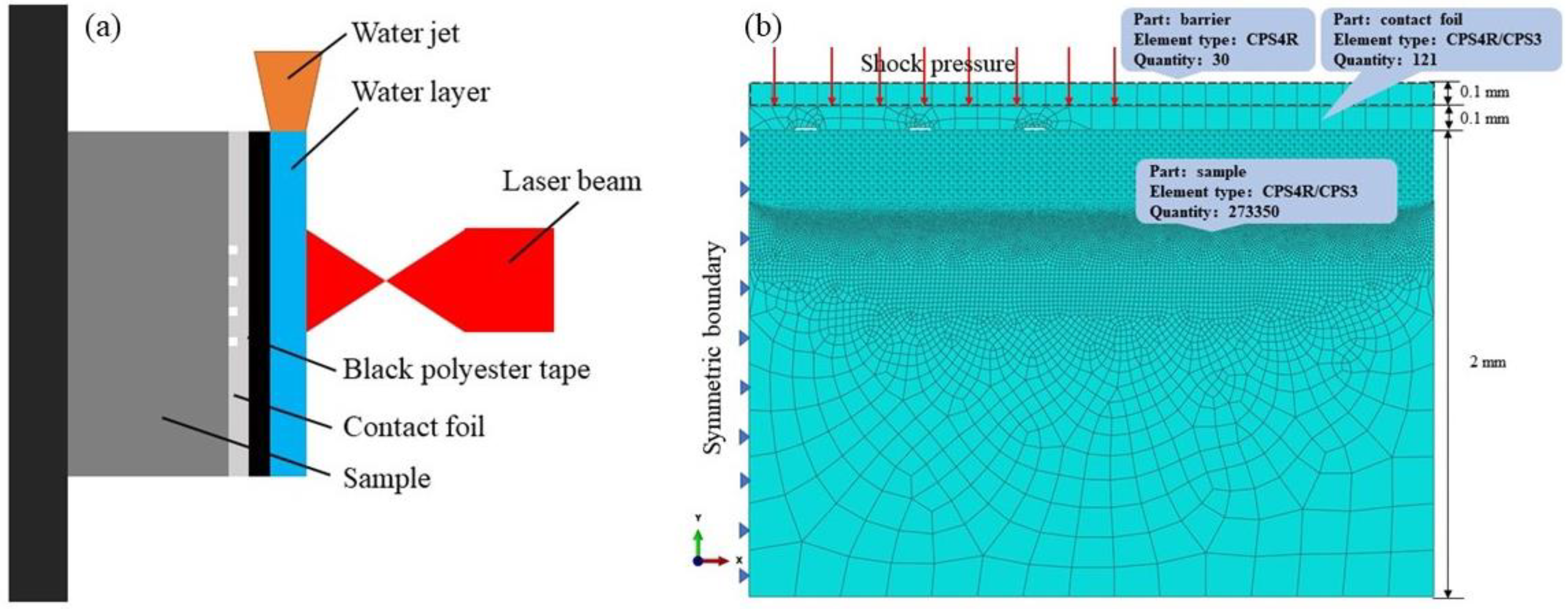
2.1. FEM Simulation

A two-dimensional model was used to simulate the LSI process, as shown in Figure 1b. The upward movement of the contact foil would be limited by the aluminum foil in the experiment. Therefore, in order to make the moving process of the contact foil similar to that in the experiment, 0.1 mm aluminum was placed on the contact foil to act as a barrier. The shock pressure was directly loaded onto the contact foil surface.
The mesh division of the FEM model was as follows: Firstly, the surface deformations of the barrier and contact foil were not considered in the research process; therefore, these two parts were divided into coarse meshes, where the mesh size was 0.1 mm × 0.1 mm and the mesh types were CPS4R (two-dimensional, four nodes) and CPS3 (two dimensions), respectively. Secondly, the surface layer with a depth of 0.3 mm was subdivided into meshes with a unit size of 0.002 mm × 0.002 mm. The middle layer adopted transition meshes (unit size of 0.02 mm × 0.02 mm), and the bottom layer adopted coarse meshes (unit size of 0.2 mm × 0.2 mm). The mesh types were CPS4R and CPS3, and the total number of elements was 273,350.
Due to the fact that the embossment and sink in the special zone of the sample treated by LSI belong to deformation at the ultra-high strain rate, the effect of strain on the material properties should be considered [15]. The Johnson–Cook model of isotropic hardening was adopted in this paper [16], and the mechanical parameters are shown in Table 1.
The energy of the laser shock wave was equivalent to the uniform pressure in an ultra-short time. Berthe et al. [17] found that the action time of laser shock wave to material with a water confining layer was about 2–3 times longer than that without a confining layer. In this paper, the pulse duration of the nanosecond laser was 20 ns, so the duration of loading pressure was 40–60 ns. The time evolution of pressure conformed to the triangular ramp curve mode [18], which increased from zero to peak in a period of 20 ns, and then decreased from peak to zero in the next 40 ns. The laser spot was a circle with a diameter of 3 mm; therefore, the pressure loading area diameter was 1.5 mm, taking the left axis as the central axis because a two-dimensional symmetrical model was used in this simulation. According to the formulation derived from Fabbro et al. [19], the parameters of LSI were laser energies of 4 J, 5 J and 6 J, corresponding to loading peak pressures of 3 GPa, 4 GPa and 5 GPa, respectively.
The dynamic calculation was divided into three analysis steps: In the first step, the ABAQUS/Explicit code was adopted, the time increment was 5 ns, and the total time length was 500 ns, which made the embossment on the material surface form entirely. The time increment of the second step was 250 ns and the total time length was 15 μs, which made the material surface stable. In the third step, static and general modes were used to balance the residual stress distribution of the material. The total time length of this step was 0.5 s.

2.2. Experiment

The chemical composition of TA2 pure titanium is shown in Table 2. TA2 pure titanium was cut into a rectangular block with a size of 10 mm × 10 mm × 2 mm, and then ground and polished with sandpaper and a polishing belt, respectively. Finally, the samples were ultrasonically cleaned with alcohol.
The contact foil in this paper was 65 Mn steel with a thickness of 0.1 mm, where the hardness was 500 HV and the tensile strength was 735 MPa. The chemical composition of 65 Mn steel is shown in Table 3. The 65 Mn steel contact foil was cut to a size of 10 mm × 10 mm × 0.1 mm. A groove-like array texture was fabricated with a nanosecond pulsed laser, and then the grooved surface was polished. Figure 2 presents the schematic of the contact foil size (a) and the texture distribution (b), where the length, width and depth of the groove were 1 mm, 0.1 mm and 0.05 mm, respectively.
An Nd-YAG: GAIA nanosecond pulsed laser (Thales, Paris, French) was used to conduct LSI and LSP experiments, as shown in Figure 3. The processing parameters were as follows: the laser pulse width was 20 ns, the pulse energy was 4–6 J, the wavelength was 1064 nm, the treated area was a single laser spot, the laser pulse frequency was 1 Hz and the impact time was 1. The diameter of the laser spot reaching the target was about 3 mm. The sample was fixed onto the workbench with double-sided tape. Black polyester tape with a thickness of 200 μm was used as the absorbing layer. In LSI, the textured side of the contact foil was closely attached to the polished surface of the sample, but contact foil was not used in LSP. Running deionized water with a thickness of 1–1.5 mm was used as the confining layer.
A VK-X200 laser confocal microscope (Keyence, Osaka, Japan) was used to observe the imprinted topography on the sample surface.

3. Results and Discussion

3.1. FEM Simulation

Figure 4 presents the two-dimensional profile of the embossment on the sample surface treated with different loading peak pressures. It can be seen that the top of the embossment is flat, but with different shapes on the bottom. The bottoms of the embossments corresponding to peak pressures of 3 GPa and 4 GPa are relatively flat, while that corresponding to the pressure of 5 GPa shows a slightly bilateral asymmetry. This indicates that the value of peak pressure affects the forming inclination of the embossment bottoms. When the peak pressures are 3 GPa, 4 GPa and 5 GPa, the heights of the embossment are 1 μm, 1.7 μm and 2.7 μm, respectively.
The height of the embossment is set as the displacement between the highest point and the lowest point of the embossment. Figure 5 shows the dynamic height variation of the embossment within 15,000 ns. The change in embossment forming height within the first 500 ns is also shown in Figure 5b to clearly observe the dynamic deformation behavior of the embossment. The main forming stage of the embossment is within the first 200 ns. After 200 ns, the height of the embossment only fluctuates slightly, which has a small effect on the final determination of the embossment height. It can be seen from Figure 5a that the forming process of the embossment can be divided into five stages, that is, static, growth, rebound, fluctuation and stabilization. In general, the final height of the embossment increases with the increase in peak pressure. The forming process of the embossment can be summarized specifically as follows. When pressure acts on the contact foil, it first propagates inside the foil for 10 ns, and then arrives at the sample surface. The zone of the sample corresponding to the texture zone of the contact foil is embossed, and the embossment is initiated. The embossment increases to the maximum height and then rebounds due to the attenuation of shock pressure. After rebounding to a certain extent, the residual energy of the shock wave makes the height of embossment show a fluctuating effect. The final embossment is generated after a longer stabilization stage.
Contact pressure plays the most important role in the formation of embossment. Figure 6 presents the contact pressure evolution of the embossment bottom at different peak pressures. The contact between the foil and sample surface mainly occurs in the first 200 ns. When the peak pressure increases from 3 GPa, to 4 GPa, to 5 GPa, the contact pressure increases from 1800 MPa, to 2300 MPa, to 3000 MPa, respectively, and the action time of loading pressure is also extended from 120 ns, to 150 ns, to 150 ns, respectively. The contact pressure evolution of the first 50 ns is extracted. It can be seen that it takes 10 ns for the pressure wave to propagate to the sample surface.
Figure 7 presents the velocity evolution of the top and the bottom of the embossment at different peak pressures. It can be seen that the bottom starts to move at 10 ns, which is the same as the initial moment of loading pressure acting on the sample surface. The top starts to move at the moment of 35 ns, which is later than the moment of the bottom moving. In addition, compared with the velocity evolution of the top, the bottom has higher values of velocity and larger fluctuation. The velocities of the two parts approach zero at the moment of 250 ns, and then keep a small fluctuation. To sum up, the pressure wave propagates to the sample surface at the moment of 10 ns, and then the bottom undergoes downward deformation movement upon the impact of the contact foil. Due to the guidance of the groove texture on the foil surface, the bottom begins to squeeze the top, which makes the top deform upward at the moment of 35 ns. The main period of the velocities of the top and the bottom is 0–250 ns, followed by a slow fluctuation stage. The displacement movement of the bottom and top together promotes the formation of the embossment.
Figure 8 presents the residual stress distribution inside the sample at different peak pressures. It can be seen that compressive residual stress with high amplitude appears in the sample, whose value increases with the increase in peak pressure. Magnified images of the special embossment zone and the surrounding zone are shown in Figure 8 to carefully observe the residual stress distribution in these two zones. The residual stress distribution in the embossment and surrounding zones treated with a loading peak pressure of 3 GPa is uniform, with values between −150 MPa and −200 MPa. The residual stress distribution in the embossment and surrounding zones treated with a peak pressure of 4 GPa is nonuniform. There is an obvious residual stress difference in these two zones, where the compressive residual stresses of the embossment and surrounding zones are approximately −150 MPa and −250 MPa, respectively. The residual stress difference can also be observed in the embossment surrounding zones of the sample treated with 5 GPa peak pressure, and an extremely high tensile residual stress exists at the edge of the embossment. This is due to the stress concentration caused by the special surface topography [20]. To sum up, a difference in residual stress appears on the embossment and surrounding zones of the sample surface treated with the peak pressures of 4 GPa and 5 GPa, which is attributed to the different plastic strain levels led by the different deformation and contact modes in the corresponding zones of the sample. There is no obvious residual stress difference between the embossment and surrounding zones in the sample treated with the 3 GPa peak pressure, which indicates that sufficient loading pressure is required to induce the stress difference between these two zones.
The residual stress distributions on the sample surface and at a 20 μm depth below the surface at a peak pressure of 5 GPa are shown in Figure 9. Tensile residual stress is found at the edge of the embossment. Compressive residual stress is dominant in the range of 0–1.4 mm, tensile residual stress is dominant at 1.4–1.8 mm, and there is almost no residual stress at 1.8–3 mm. Regarding the 20 μm depth below the surface, the residual stress distribution is still consistent with the spatial distribution of the surface topography, but it is more moderate as a whole. The compressive residual stress at 0–1.4 mm is between −180 and −350 MPa, which shows the low compressive residual stress in the central zone of the embossment. The compressive residual stress at 1.4 mm starts to weaken and gradually transforms into tensile residual stress, and finally decreases to zero at 2 mm.

3.2. Experiment Results

Figure 10 shows the embossments on the sample surface treated with different laser energies. It can be seen that there was not a large deformation on the surface of the 4 J sample, with the average embossment height being 3.5 μm. As for the 5 J sample, a certain tilt appeared on the sample surface, and the spatial distribution of embossments became nonuniform. The average embossment height was 5 μm. When the laser energy increased to 6 J, the sample surface tilt increased further; meanwhile, the clarity of the embossments also increased, accompanied by the average embossment height increasing to 6 μm. To sum up, with an increase in laser energy, the tilt on the sample surface increases, and the height of embossments also increases. The results of the experiment are similar to that of the FEM simulation.
According to the above analysis, the dynamic forming process of the embossment at a single shock pressure can be divided into five stages, as shown in Figure 11 (taking the sample treated with a peak pressure of 5 GPa as an example).
In the first stage (static stage, 0–10 ns), the loading pressure wave propagates from the contact foil to the sample surface and drives the interaction between the foil and the sample. This stage is only the propagation of the pressure wave, without the generation of contact pressure on the sample surface.
In the second stage (embossment growth stage, 10–120 ns), the material surface starts to respond after contact pressure is generated on the sample. When the accumulated stress exceeds the dynamic yield strength of the material, deformation occurs on the sample surface and the extrusion happens at the moment of 35 ns under the guidance of the contact foil. The embossment is formed and reaches the maximum height at 120 ns.
In the third stage (embossment rebound stage, 120–200 ns), the pressure wave attenuates over time, which leads to a decrease in the deformation rate of the sample surface. The elastically deformed part of the sample starts to rebound, and the velocities of the compression and extrusion at the sample top and bottom decrease. This makes the embossment height decrease in this stage.
In the fourth stage (embossment fluctuation stage, 200–15,000 ns), the internal rebound of the sample and the gradual attenuation of the pressure wave mutually restrict each other, and jointly promote height fluctuation of the embossment. In this stage, there is a small variation in the formation height of the embossment.
In the fifth stage (stabilization stage, 15 μs–0.5 s), the embossment on the sample surface has been formed generally in the first 15 μs. In this stage, the surface topography is further stabilized. The residual stress is regularly distributed in the embossment and surrounding zones. The height of the embossment reduces slightly under the effect of residual stress until the final balanced state.
Figure 12 presents the surface morphology of (a) as-received, (b) 5 J LSP and (c) 5 J LSI samples, and the profiles of all samples. It can be seen that the original surface roughness of the as-received sample was 1.904 μm, and there was only low tilt in the surface profile. Regarding the 5 J LSP sample, the surface roughness increased to 4.273 μm and large fluctuation occurred on the surface. As for the 5 J LSI sample, the surface roughness decreased to 2.259 μm, which was 47% lower than that of the 5 J LSP sample. Only low tilt appeared on the 5 J LSI sample, whose surface profile was flatter than that of the 5 J LSP sample. This indicates that the irregular morphology induced by the laser shock wave on the material surface can be eliminated by contact foil. Compared with LSP, the roughness induced by LSI on the material surface is lower, with a value close to that of the as-received sample.

4. Conclusions

TA2 pure titanium was treated by LSI technology. The surface response under an ultra-high shock wave was simulated by FEM, which involved the surface deformation process, contact pressure change and residual stress distribution in the sample. The FEM simulation was combined with experiments to understand the forming process of the embossment on the titanium surface. Finally, the surface morphologies of titanium treated by LSP and LSI were compared to verify the guidance effect of LSI on the sample surface. The conclusions are as follows:
(1)
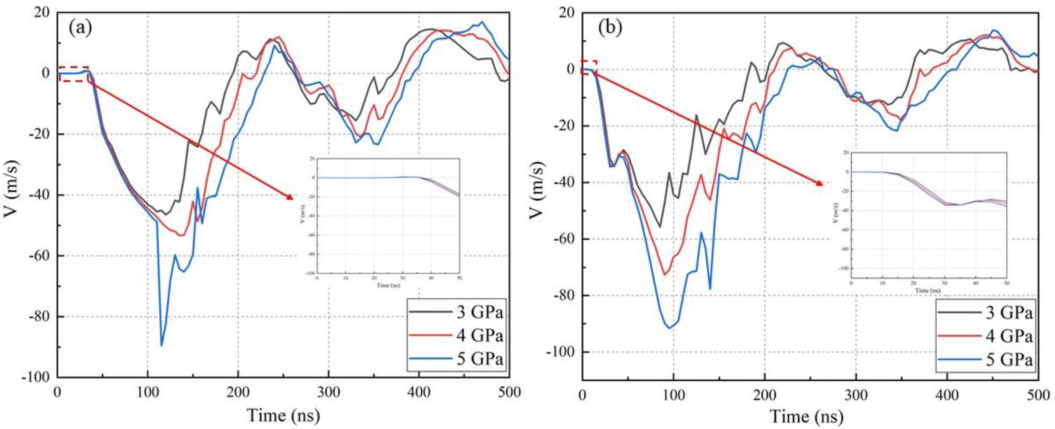
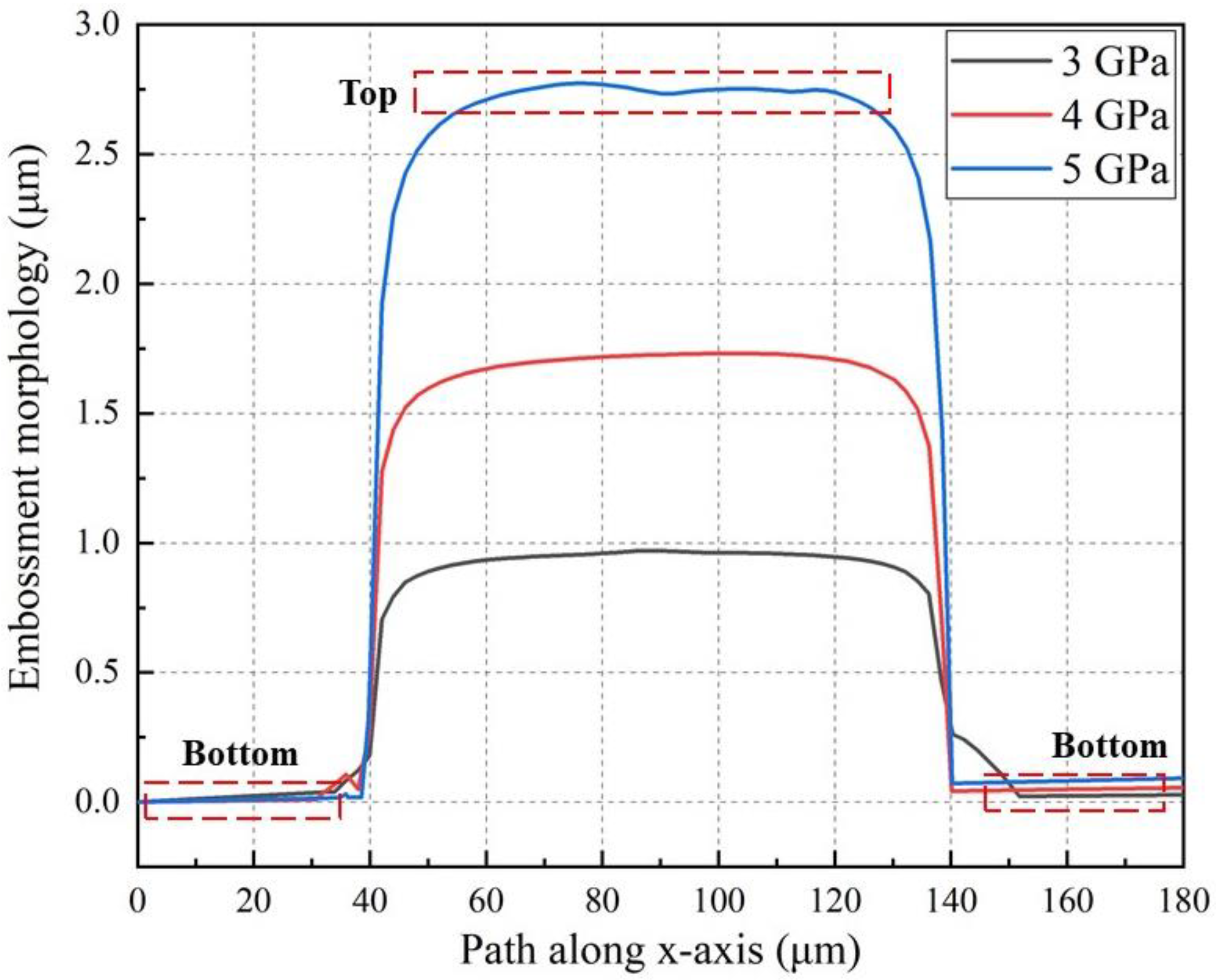
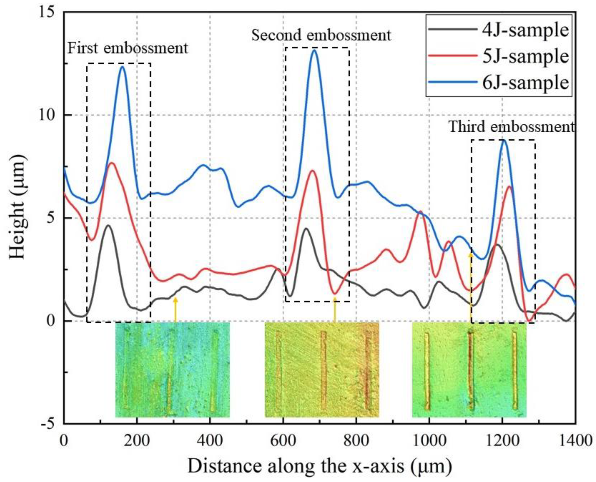
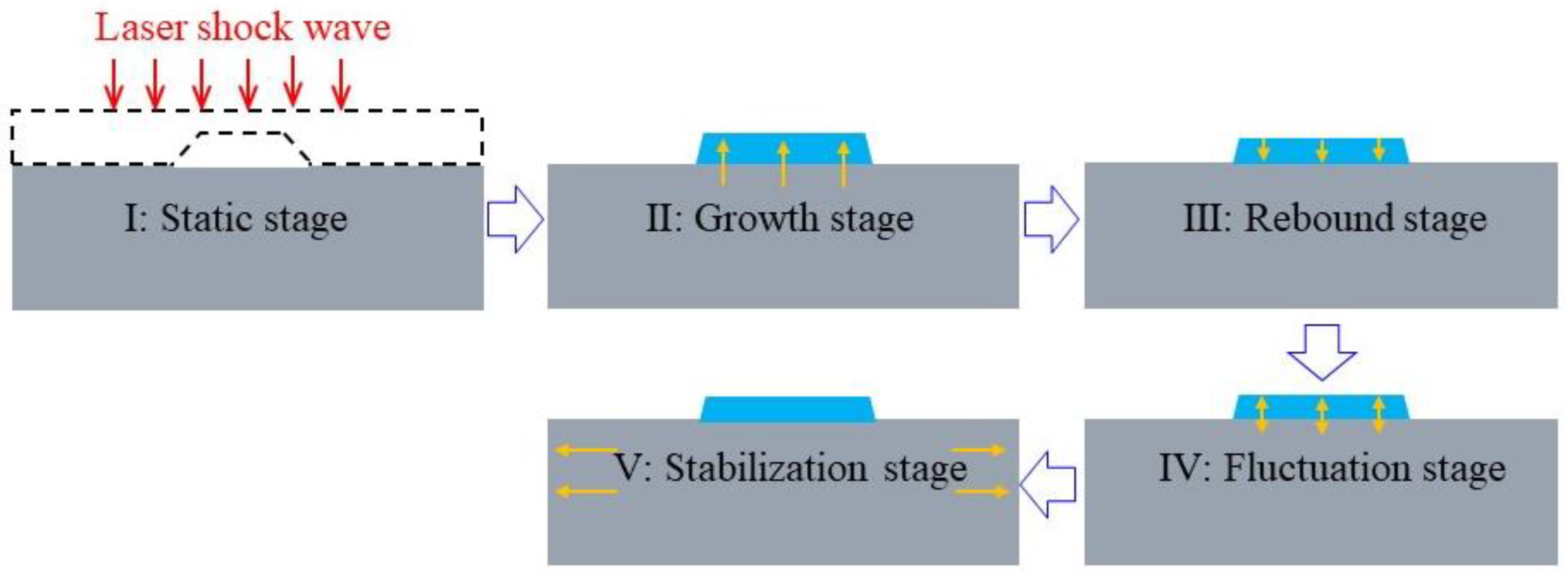
The height of the embossment is proportional to the loading peak pressure. With an increase in loading pressure, the contact pressure and time between the sample surface and the contact foil increase, and the height of the embossment also increases. The forming process of the embossment on the sample surface can be divided into the stages of static, growth, rebound, fluctuation and stabilization.
(2)
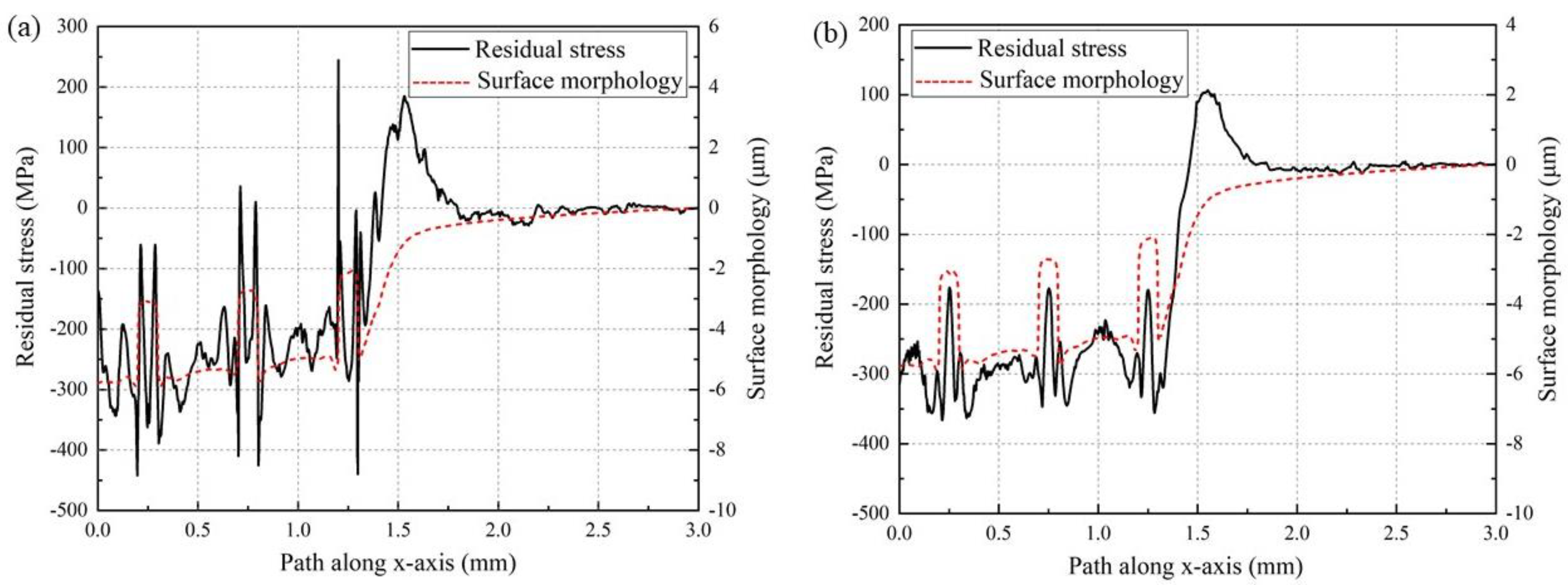
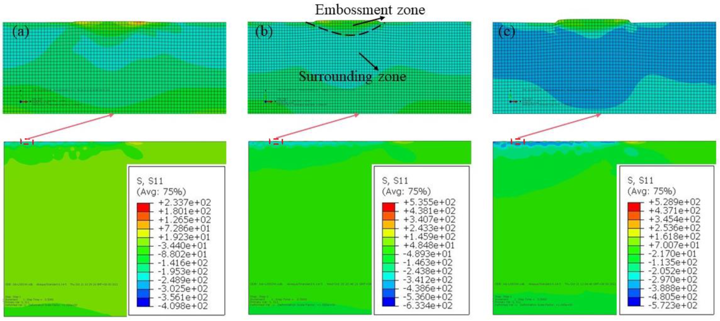
A difference in residual stress between the embossment and surrounding zones is generated when the loading pressure increases to a certain extent, and extremely high tensile residual stress also appears on the edge of the embossment.
(3)
With an increase in laser energy, the clarity and height of the embossment increased, and the tilt of the sample surface also increased.
(4)
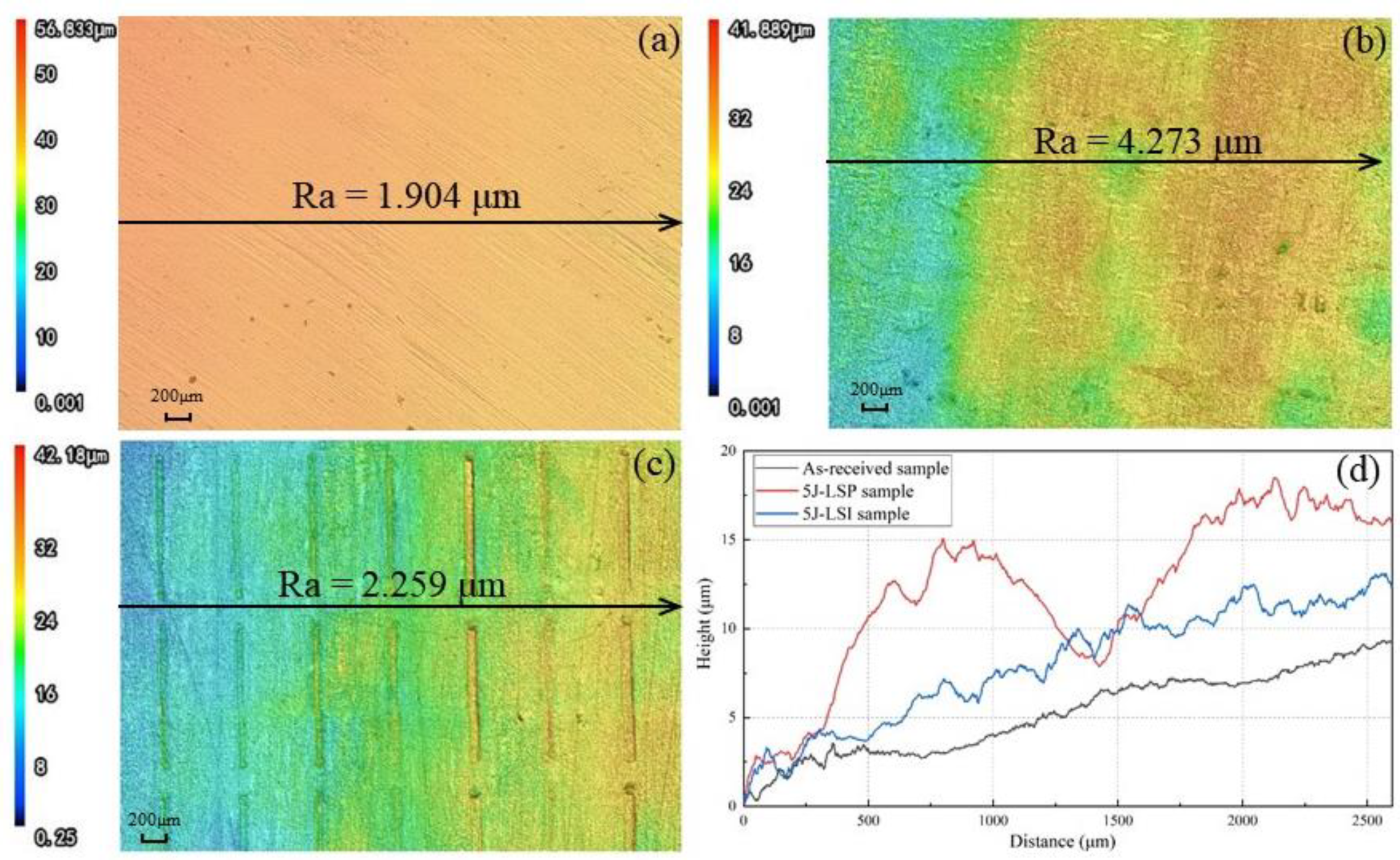
Compared with the LSP sample, the surface roughness of the sample treated by LSI was 47% lower, with a flatter surface profile. The irregular morphology induced by the laser shock wave on the sample surface was changed into a single tilt under the effect of the contact foil.

Author Contributions

W.C.: literature search, figures, data collection, data analysis, writing/or criteria 1. F.D.: study design, writing, supervision, interpretation of data, funding/or criteria 2. S.H.: acquisition and analysis of the work/or criteria 2. S.K.: review, funding/or criteria 2. X.C.: study design, Conception, supervision, Funding/or criteria 3. All authors have read and agreed to the published version of the manuscript.

Funding

This research was funded by Key Research and Development Project of Zhejiang Province: 2021C04022.

Institutional Review Board Statement

This study did not require ethical approval.

Informed Consent Statement

Informed consent was obtained from all subjects involved in the study.

Data Availability Statement

The available data had been added into the paper.

Conflicts of Interest

The authors declare no conflict of interest.

References

  1. Chattopadhyay, A.; Muvvala, G.; Sarkar, S.; Racherla, V.; Nath, A.K. Effect of laser shock peening on microstructural, mechanical and corrosion properties of laser beam welded commercially pure titanium. Opt. Laser Technol. 2021, 133, 106527. [Google Scholar] [CrossRef]
  2. Wang, C.; Li, K.F.; Hu, X.Y.; Yang, H.T.; Zhou, Y.J. Numerical study on laser shock peening of TC4 titanium alloy based on the plate and blade model. Opt. Laser Technol. 2021, 142, 107163. [Google Scholar] [CrossRef]
  3. Qiao, H.C.; Gao, Y.; Zhao, J.B.; Lu, Y.; Zhao, Y.X. Research progress of laser shock strengthening technology. Chin. J. Nonferrous Met. 2015, 25, 1744–1755. [Google Scholar]
  4. Wang, C.Y.; Cheng, W.; Shao, Y.K.; Luo, K.Y.; Lu, J.Z. Cavitation erosion behaviour of AISI 420 stainless steel subjected to laser shock peening as a function of the coverage layer in distilled water and water-particle solutions. Wear 2021, 470–471, 203611. [Google Scholar] [CrossRef]
  5. Dai, F.Z.; Cheng, W.; Zheng, Y.Y.; Chen, X.Z. The effect of rolling contact fatigue properties on 316 stainless steel under laser shock peening. Opt. Laser Technol. 2021, 141, 107159. [Google Scholar] [CrossRef]
  6. Cao, Y.P.; Zhou, D.C.; Feng, A.X.; Hua, G.R.; Jiang, S.Z. Mechanism of residual stress holes formed in laser shock 7050 aluminum alloy sheet sample. Chin. J. Lasers 2016, 43, 2–8. [Google Scholar]
  7. Feng, Y.Y.; Ye, Y.X.; Lian, Z.Y.; Xuan, T. Effect of laser shock peening on the copper surface quality. Laser Optoelectron. Prog. 2015, 52, 198–204. [Google Scholar]
  8. Maawada, E.; Sano, Y.; Wagner, L.; Brokmeier, H.-G.; Genzel, C. Investigation of laser shock peening effects on residual stress state and fatigue performance of titanium alloys. Mater. Sci. Eng. A 2012, 536, 82–91. [Google Scholar] [CrossRef]
  9. Dai, F.Z.; Lu, J.Z.; Zhang, Y.K.; Luo, K.Y.; Wang, Q.W.; Zhang, L.; Hua, X.J. Effect of initial surface topography on the surface status of LY2 aluminum alloy treated by laser shock processing. Vacuum 2012, 86, 1482–1487. [Google Scholar] [CrossRef]
  10. Yella, P.; Venkateswarlu, P.; Buddu, R.K.; Vidyasagar, D.; Rao, K.B.S.; Kiran, P.P.; Rajulapati, K.V. Laser shock peening studies on SS316LN plate with various sacrificial layers. Appl. Surf. Sci. 2018, 435, 271–280. [Google Scholar] [CrossRef]
  11. Salimianrizi, A.; Foroozmehr, E.; Badrossamay, M.; Farrokhpour, H. Effect of Laser Shock Peening on surface properties and residual stress of Al6061-T6. Opt. Lasers Eng. 2016, 77, 112–117. [Google Scholar] [CrossRef]
  12. Zou, S.K.; Gong, S.L.; Guo, E.M.; Li, B. Laser shock peening of integral blade disk of engine. Chin. J. Lasers 2011, 38, 91–97. [Google Scholar]
  13. Zoua, S.; Wua, J.; Zhang, Y.; Gong, S.; Sun, G.; Ni, Z.; Cao, Z.; Che, Z.; Feng, A. Surface integrity and fatigue lives of Ti17 compressor blades subjected to laser shock peening with square spots. Surf. Coat. Technol. 2018, 347, 398–406. [Google Scholar] [CrossRef]
  14. Dai, F.; Zhou, J.; Lu, J.; Luo, X. A technique to decrease surface roughness in overlapping laser shock peening. Appl. Surf. Sci. 2016, 370, 501–507. [Google Scholar] [CrossRef]
  15. Chakrabarty, R.; Song, J. A modified Johnson-Cook material model with strain gradient plasticity consideration for numerical simulation of cold spray process. Surf. Coat. Technol. 2020, 397, 125981. [Google Scholar] [CrossRef]
  16. Johnson, G.J.; Cook, W.H. A constitutive model and data for metals subjected to large strains, high strain rates and high temperatures. Eng. Fract. Mech. 1983, 21, 541–547. [Google Scholar]
  17. Berthe, L.; Fabbro, R.; Peyre, P.; Tollier, L.; Bartnicki, E. Shock waves from a water-confined laser-generated plasma. J. Appl. Phys. 1997, 82, 2826–2832. [Google Scholar] [CrossRef]
  18. Braisted, W.; Brockman, R. Finite element simulation of laser shock peening. Int. J. Fatigue 1999, 21, 719–724. [Google Scholar] [CrossRef]
  19. Fabbro, R.; Fournier, J.; Ballard, P.; Devaux, D.; Virmont, J. Physical study of laser produced plasma in confined geometry. J. Appl. Phys. 1990, 68, 775–784. [Google Scholar] [CrossRef]
  20. Sun, J.X.; Guo, Z.G.; Zhao, X.Q.; Li, X.L.; Luo, J. A calculation method for stress concentration factor of grinding surface micro morphology. Mech. Sci. Technol. Aerosp. Eng. 2020, 39, 380–384. [Google Scholar]
Figure 1. LSI schematic (a) and finite element model (b).
Metals 12 01031 g001
Figure 2. Schematics of contact foil size (a) and texture size (b).
Metals 12 01031 g002
Figure 3. GAIA nanosecond pulse laser shock system: (a) laser system, (b) computer-integrated control system, (c) workbench and (d) path control system.
Metals 12 01031 g003
Figure 4. Profile of the embossments at different peak pressures.
Metals 12 01031 g004
Figure 5. Evolution of embossment height at different peak pressures with time, where (b) shows in detail the first 500 ns of (a).
Metals 12 01031 g005
Figure 6. Contact pressure evolution of the embossment bottom at different peak pressures.
Metals 12 01031 g006
Figure 7. Velocity evolution of the embossment top (a) and bottom (b) at different peak pressures.
Metals 12 01031 g007
Figure 8. Residual stress distributions inside the sample and around the specific embossment at different peak pressures: (a) 3 GPa, (b) 4 GPa and (c) 5 GPa.
Metals 12 01031 g008
Figure 9. Residual stress distribution on the sample surface (a) and residual stress distribution at a depth of 20 μm below the surface (b), under a peak pressure of 5 GPa.
Metals 12 01031 g009
Figure 10. Surface topography of the samples treated with different laser energies.
Metals 12 01031 g010
Figure 11. Schematic of the embossment forming process on the sample surface subjected to LSI treatment.
Metals 12 01031 g011
Figure 12. Surface morphology of (a) as-received, (b) 5 J LSP and (c) 5 J LSI samples, and (d) profiles.
Metals 12 01031 g012
Table 1. Mechanical parameters of 65 manganese steel and TA2 titanium alloy.
MaterialΡ (kg/m3)A (MPa)B (MPa)nCE (GPa)υ
65 Mn steel781098020000.830.00262000.288
Pure titanium450043010000.30.0471080.3
Table 2. Chemical composition of TA2 pure titanium.
ElementsFeCNHOTi
Weight%≤0.30≤0.10≤0.05≤0.015≤0.25balance
Table 3. Chemical composition of 65 Mn steel.
ElementsCSiMnSCrNiCuFe
Weight%0.62–0.700.17–0.370.9–1.2≤0.035≤0.25≤0.30≤0.25balance
Publisher’s Note: MDPI stays neutral with regard to jurisdictional claims in published maps and institutional affiliations.

