
Valorizing Steelworks Gases by Coupling Novel Methane and Methanol Synthesis Reactors with an Economic Hybrid Model Predictive Controller

 , ,
, ,  ,
,  ,
,  , ,
, ,  ,
, 

Abstract
:1. Introduction
- Optimal management avoiding limiting conditions;
- Alternative POG routes exploiting carbon capture storage and usage (CCS and CCU) solutions.
2. State-of-the-Art Analysis
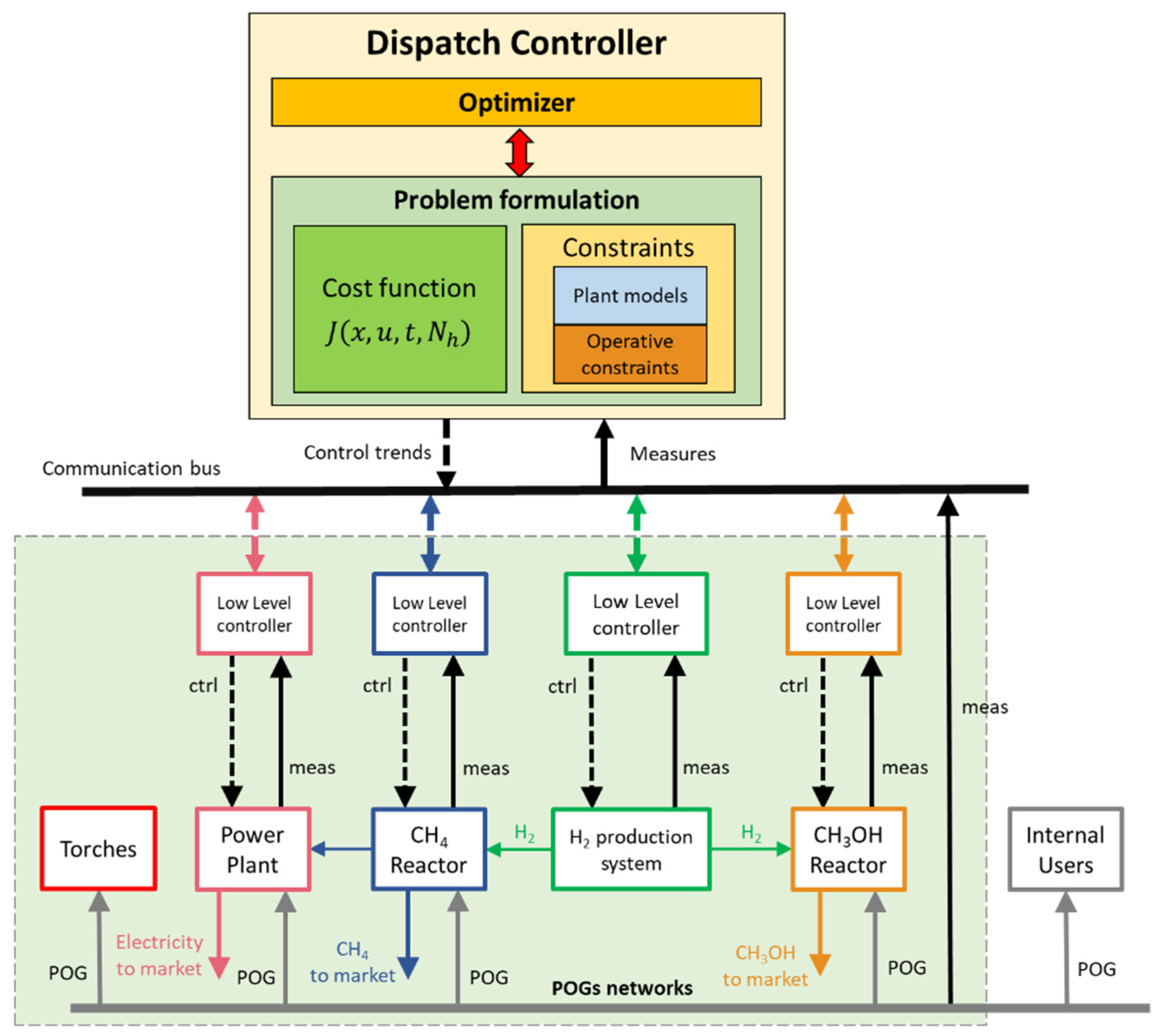
- The synchronization and control of different processes belonging to the steelmaking (i.e., internal gas users), energetic (i.e., power plant), chemical (i.e., synthesis reactors), and electrochemical (i.e., H2 production process) domains;
- The suitable distribution of POGs between standard and novel users;
- POG mixing (both pure and mixed POGs can be fed to the reactors) and enrichment with hydrogen for optimal usage in synthesis reactors;
- The correct operation of the communication structure for the transmission of the control values to the real synthesis plants;
- The smooth operation of synthesis reactors with dynamics in feed gas composition and load;
- Optimized methane and methanol production, usage, and sale.
3. Materials and Methods
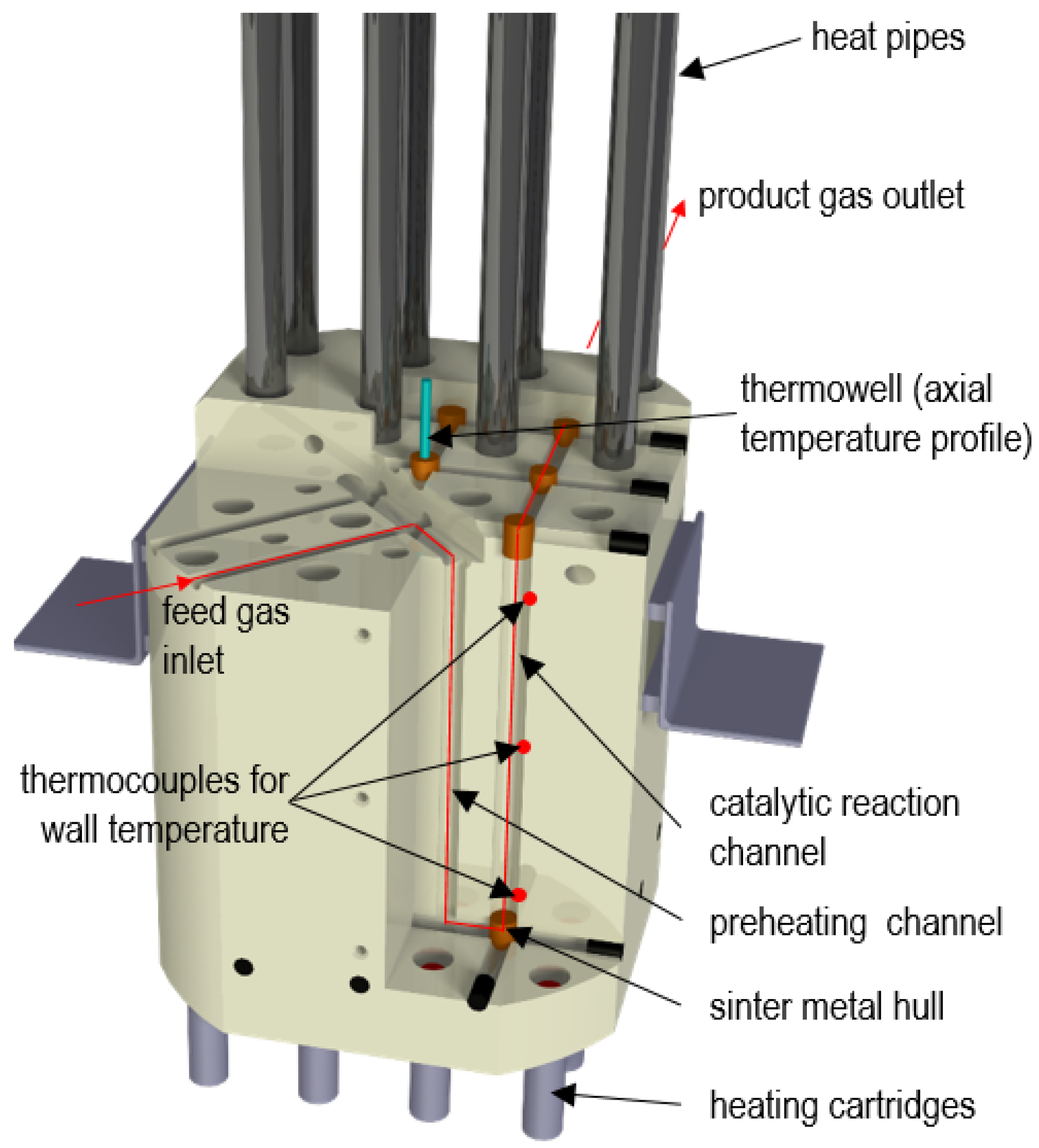
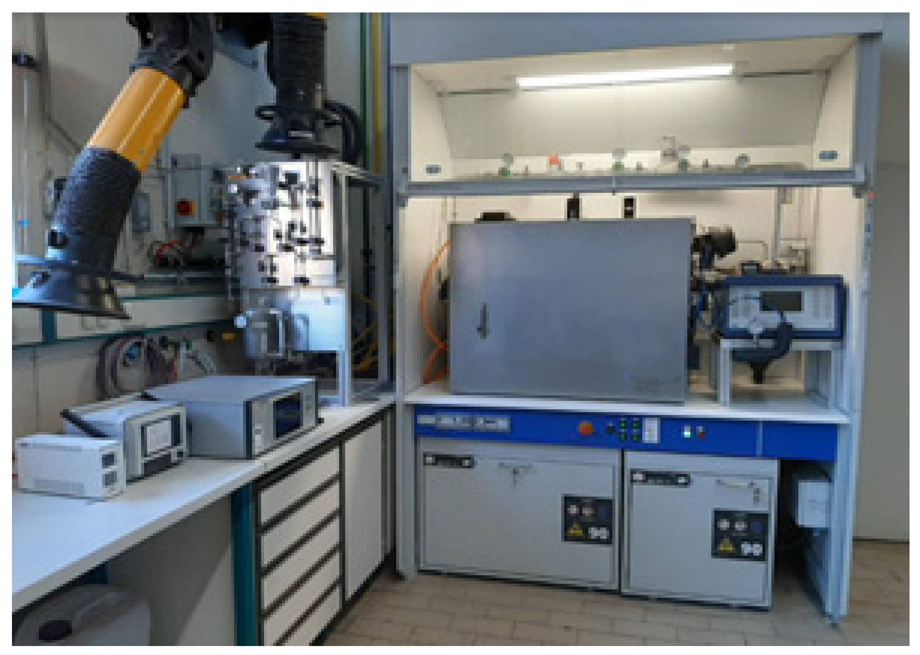
3.1. Lab-Scale Methanation Unit at Friedrich-Alexander-Universität Erlangen-Nürnberg (FAU)
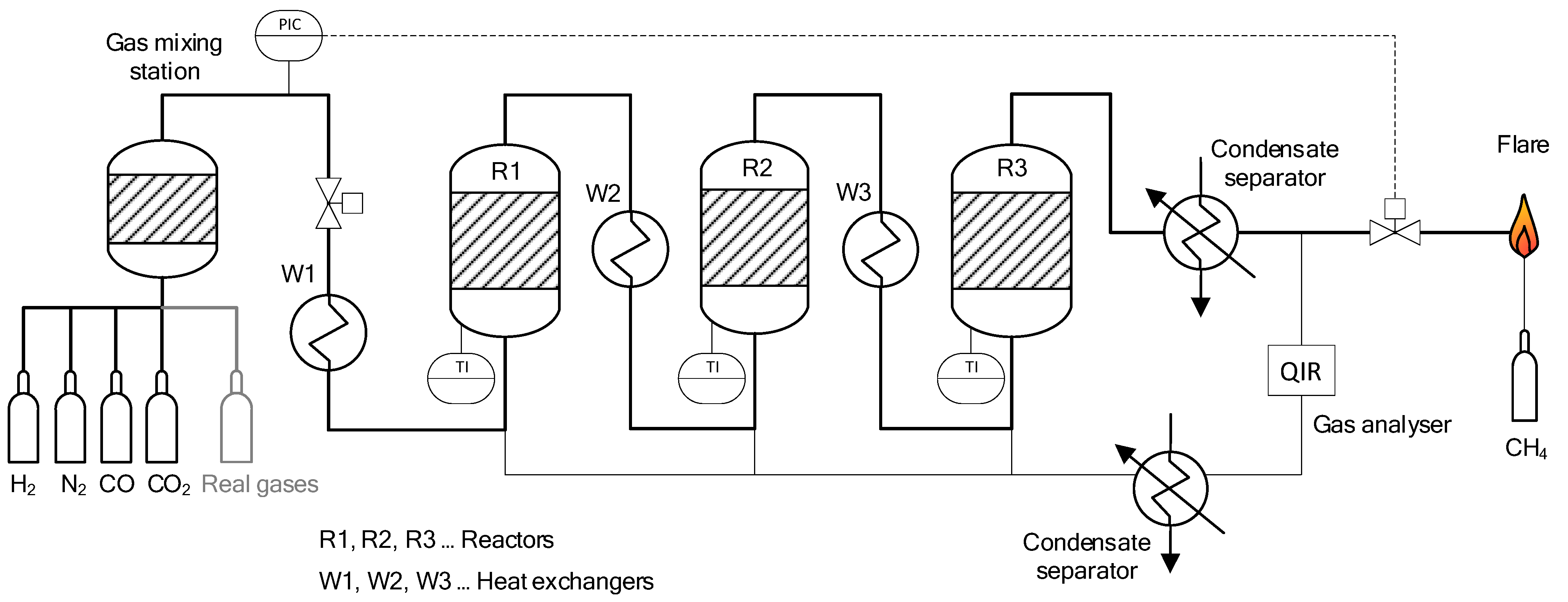
3.2. Lab-Scale Methanation Unit at Montanuniversität Leoben (MUL)
- Flow rate range: 0.3–3 Nm3/h (≈5–50 NL/min);
- Gas hourly space velocity (GHSV) range: 1200–12,000 h−1;
- Pressure rating: up to 20 bar;
- Maximum reactor temperature: 700 °C.
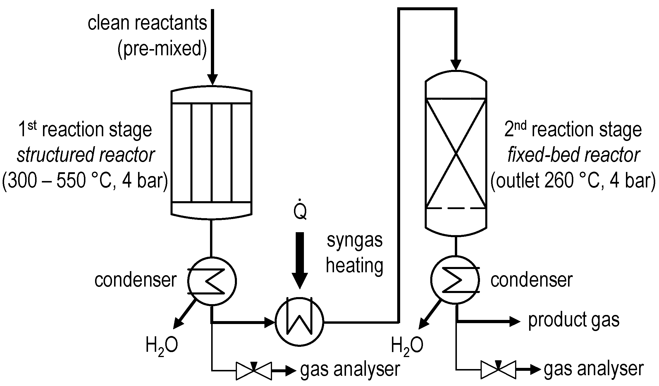
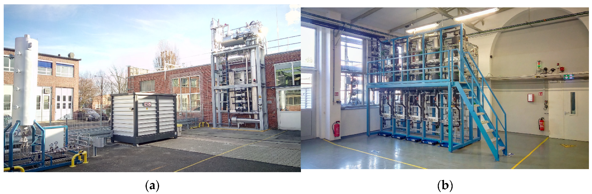
3.3. Pilot Plant for Methanol Synthesis at Air Liquide Forschung und Entwicklung (ALFE)
- Several reactor stages;
- Various possible flow schemes;
- Heat transfer to steam system;
- Temperature profile measurement in the different process stages through multi-point thermocouples;
- Throughput:
- ○
- Feed gas up to 35 Nm3/h;
- ○
- Raw methanol product up to 20 kg/h.
- Fresh feed gas was fed to stage 1 of the reaction section;
- Unconverted gases from stage 1 were fed to stage 2;
- Unconverted gases from stage 2 were fed to stage 3;
- Unconverted gases from stage 3 were fed to stage 4;
- Raw methanol product was removed after each stage and analyzed accordingly;
- By-product amounts were evaluated in the raw methanol removed between the stages;
- The final raw methanol product gathered all the contributions coming from each stage.
3.4. Dispatch Controller at ICT-COISP Center of TeCIP Institute of Scuola Superiore Sant’Anna
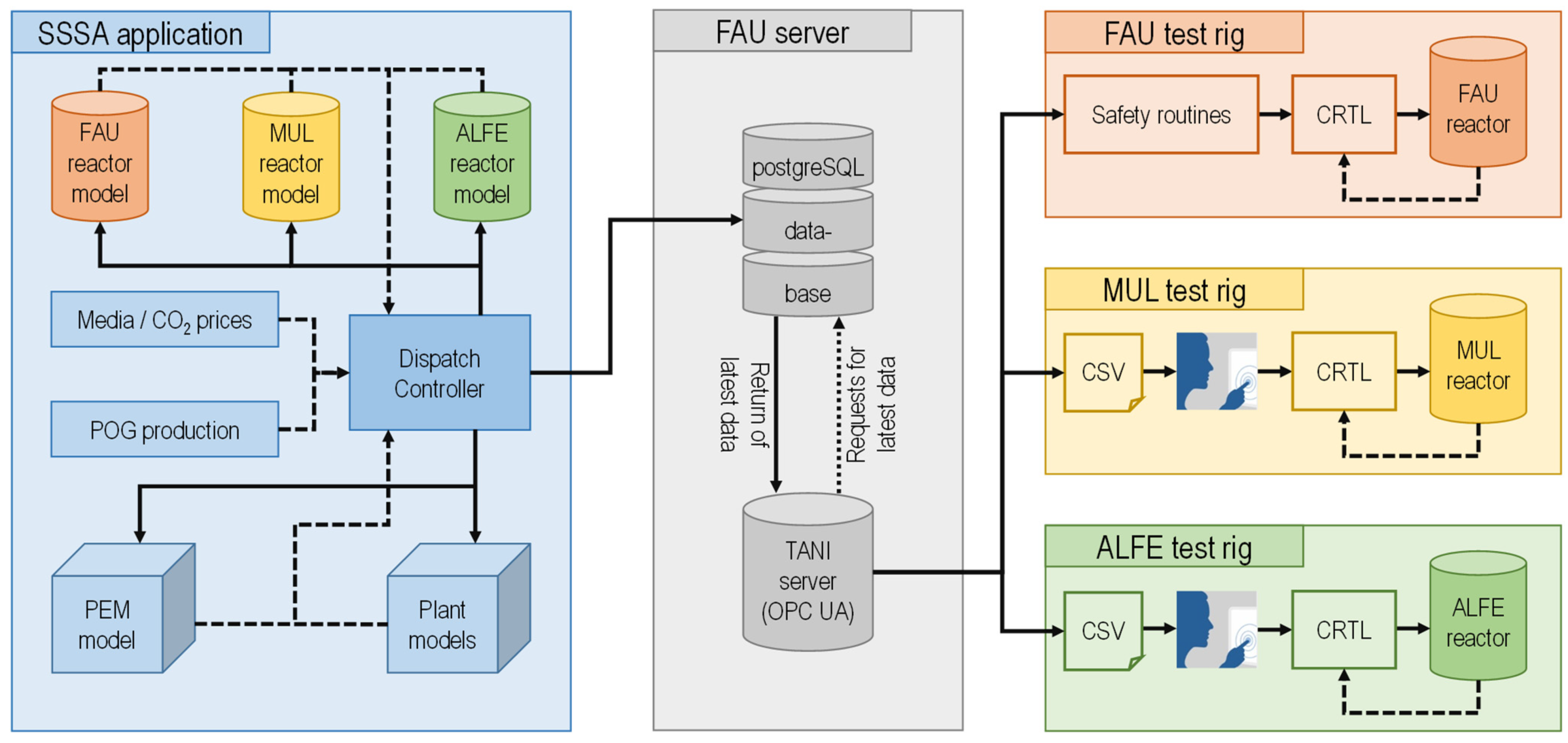
3.5. Data Communication Infrastructure
4. Results and Discussion
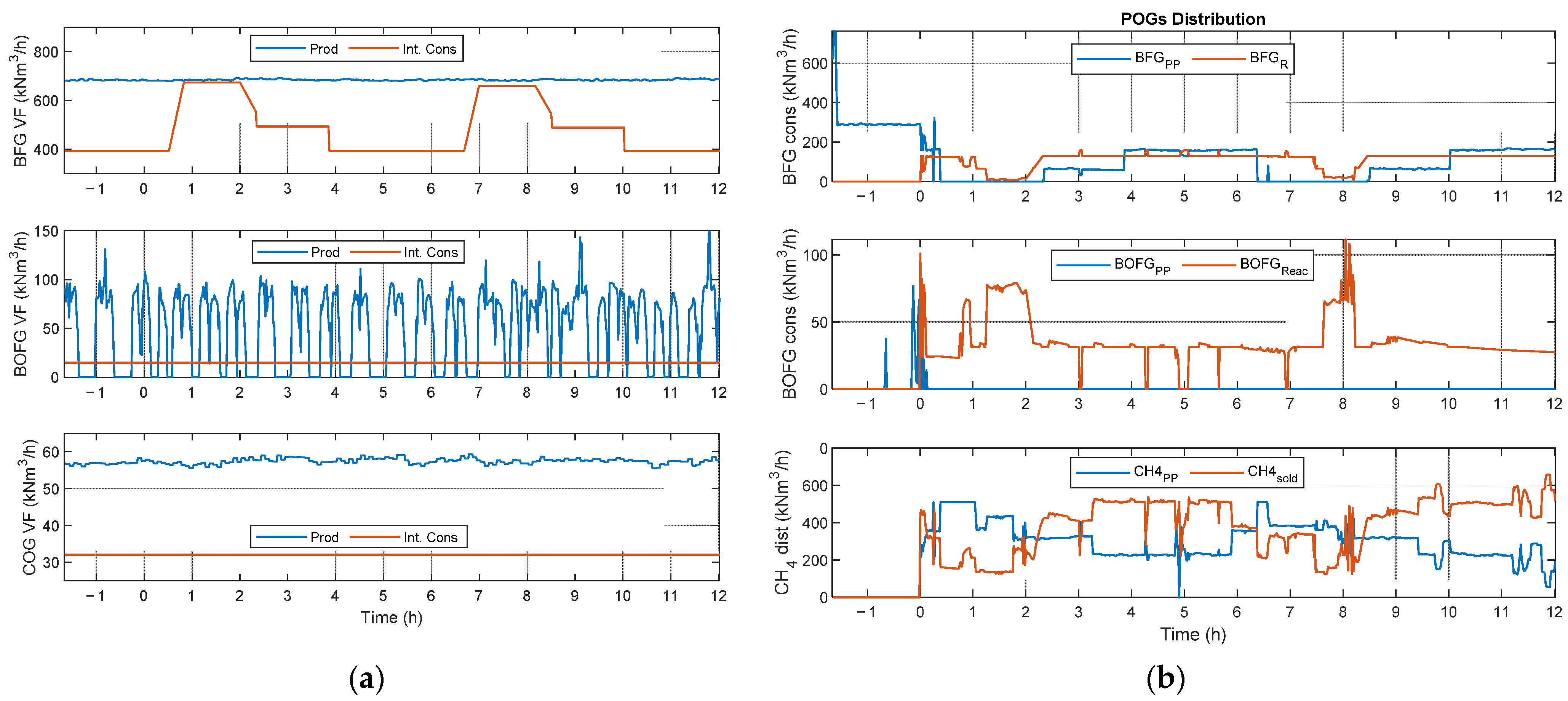
4.1. Definition of Scenarios
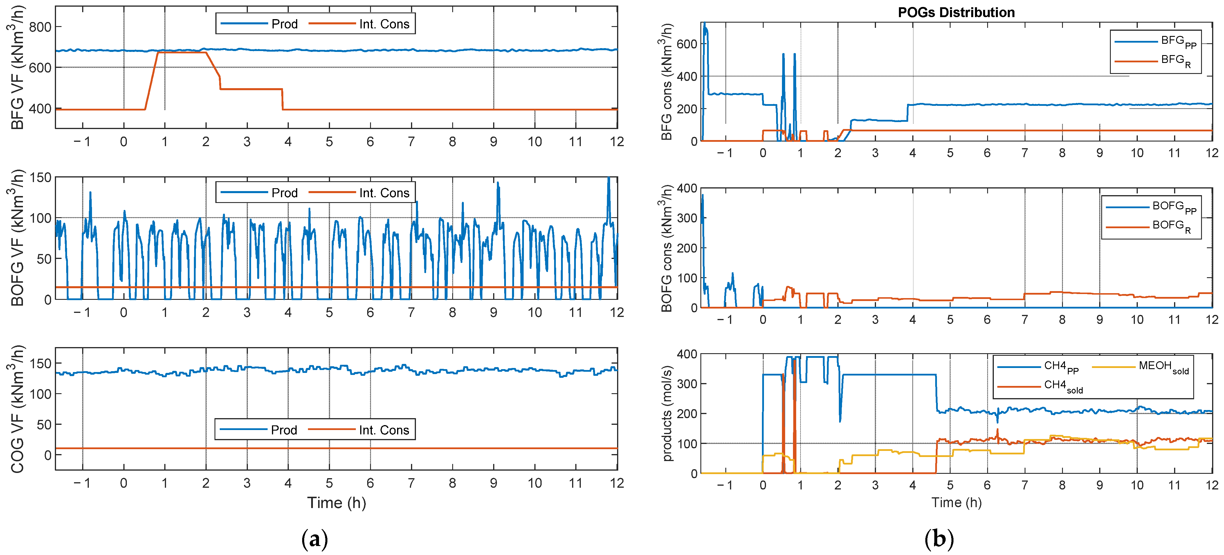
- Scenario 1 (SC1): two methane reactors (FAU_CH4_TR and MUL_CH4_TR) running in parallel in variable load conditions with strong disturbances in the BFG network, where several sequential BFG shortages are simulated;
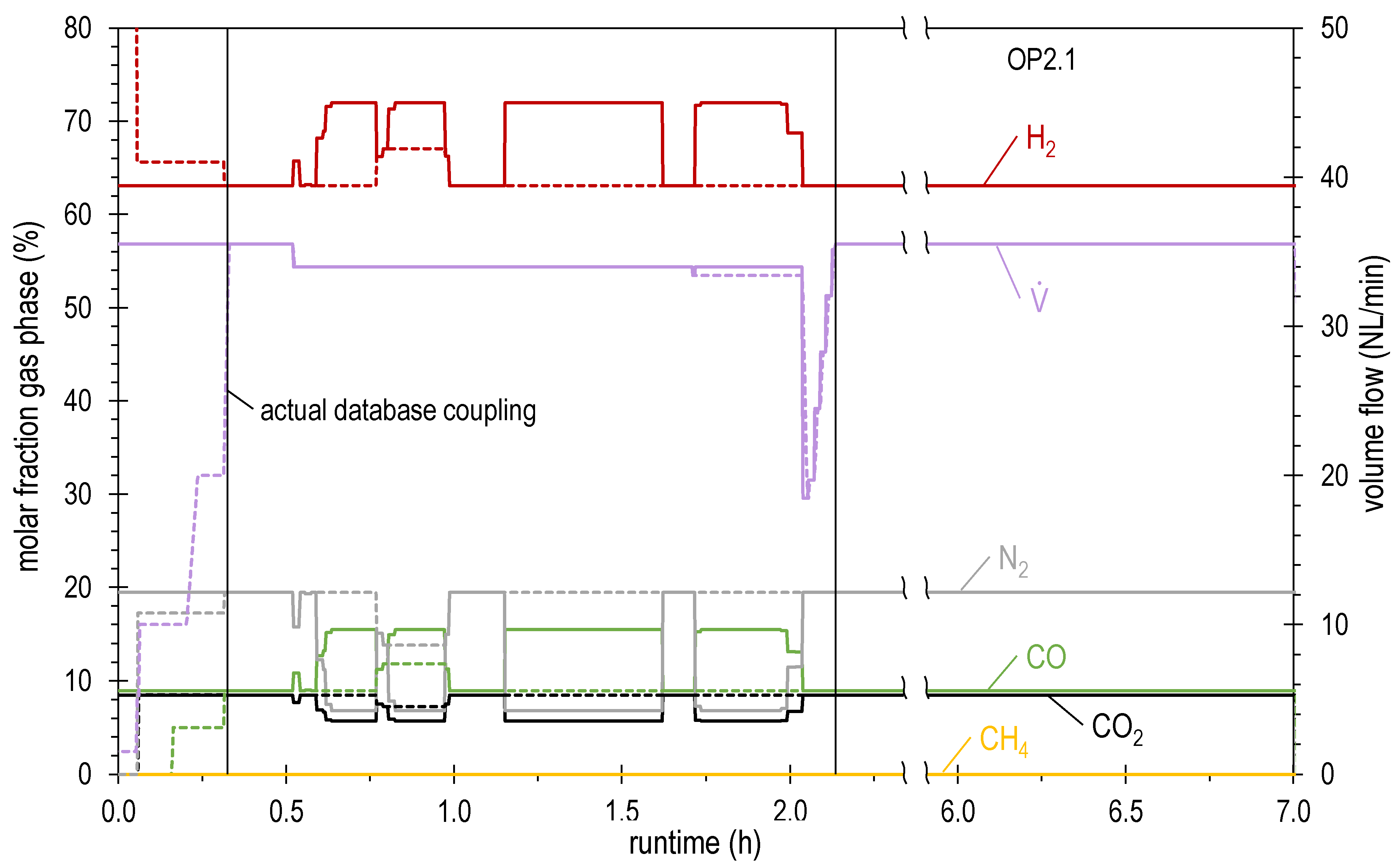
- Scenario 2 (SC2): one methane (FAU_CH4_TR) and one methanol (ALFE_CH3OH_PLP) reactor running in parallel with variable operating conditions due to a BFG shortage. This scenario is of particular interest, as it allows the simulation of a context in which it is possible to access the product market (i.e., methane, methanol, and possibly electricity) in which the flexibility and diversification of production could be an economically winning factor. In particular, considering the current variability in the prices of both electricity and products such as methane, it is considered fundamental to test the validity of the developed control approach.
- POGs distributed to the power plant and synthesis reactors;
- Produced methanol sold to external users;
- Produced methane distributed to external users and internal consumers based on the economic gain;
- A warmup phase followed by about 10–12 h of methane and/or methanol production;
- The methane reactors exploited BFG and BOFG with the constant stoichiometric number ;
- The methanol reactor exploited BFG, BOFG, and COG with ;
- The price of electricity sold to the external grid was equal to EUR 80/MWh;
- The prices of methane and methanol sold to external users were equal to EUR 25/MWh and EUR 400/ton, respectively;
- The price of CO2 emissions was equal to EUR 30/ton;
- The price of green electricity for the PEM electrolyzer was equal to EUR 5/MWh;
- The number of available PEM electrolyzer stacks was equal to 70, each characterized by a nominal power of 17.5 MW and a resulting hydrogen production of 340 kg/h at full capacity.
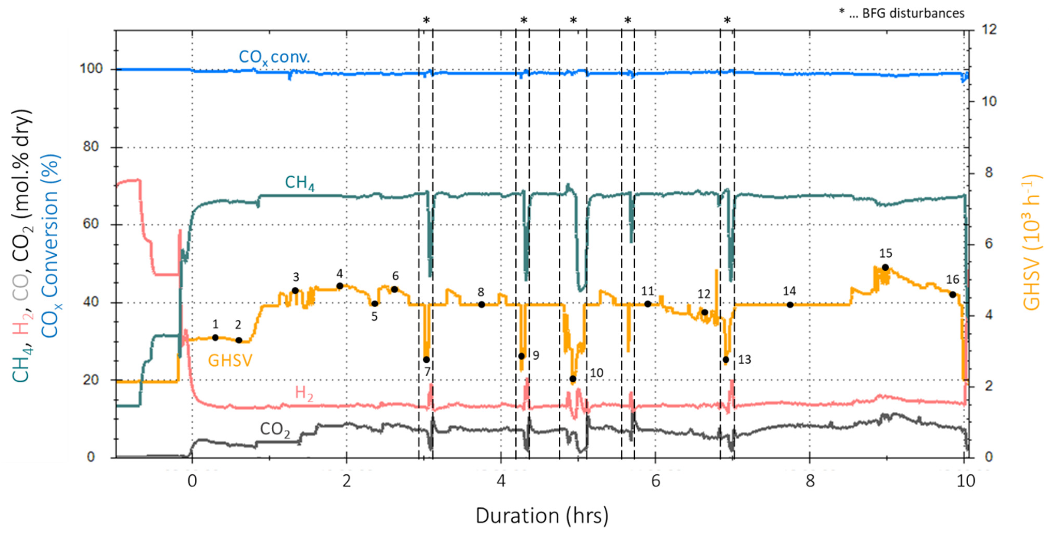
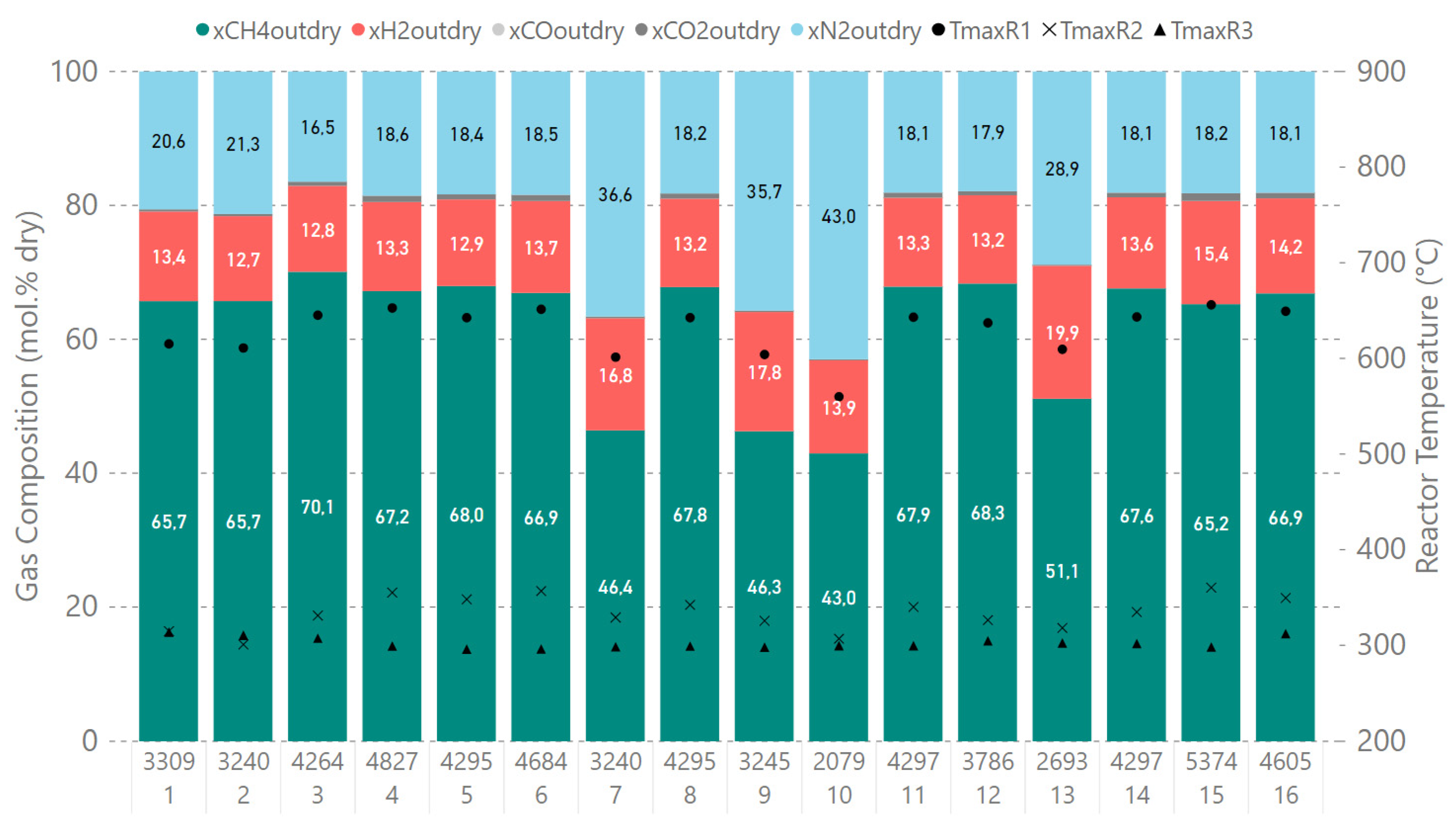
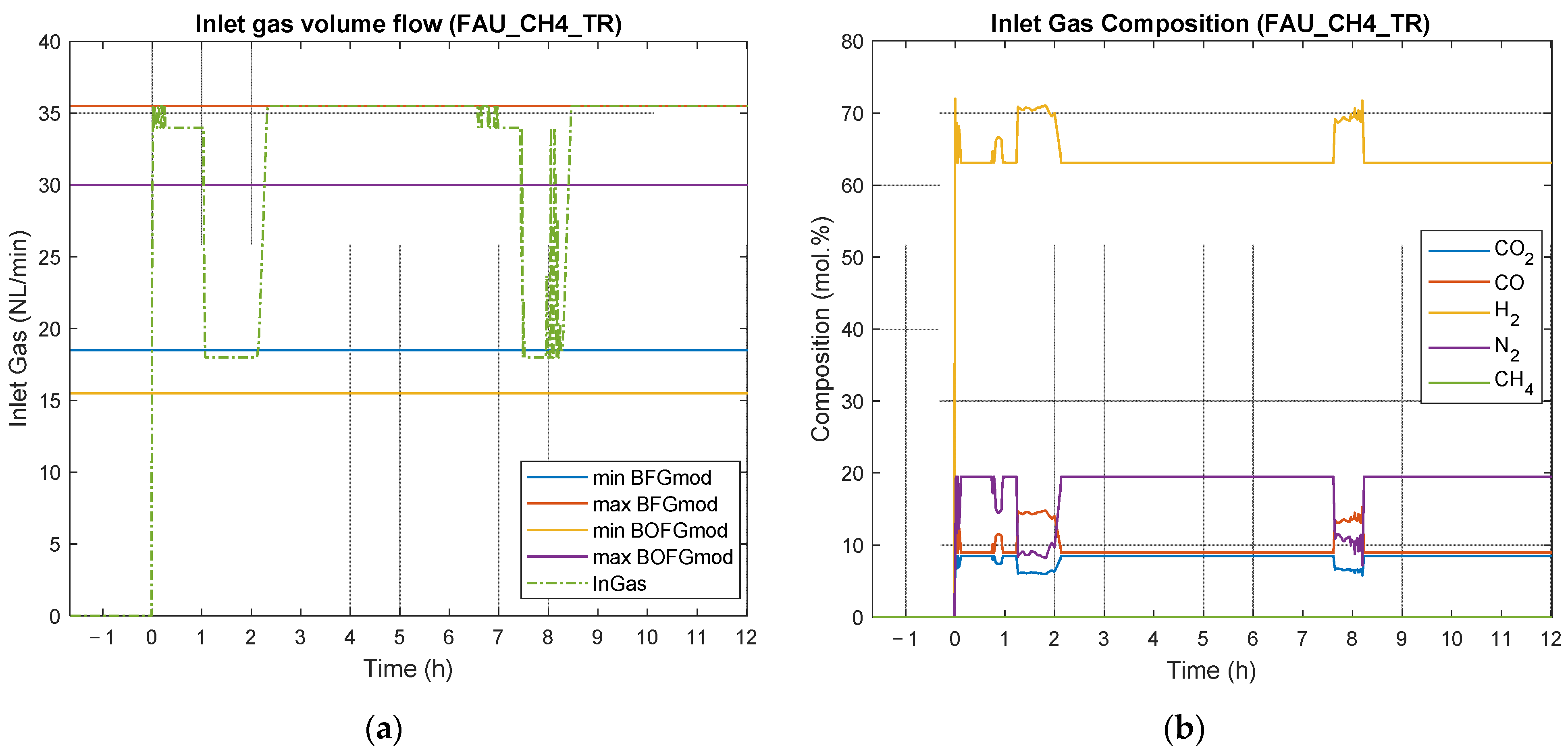
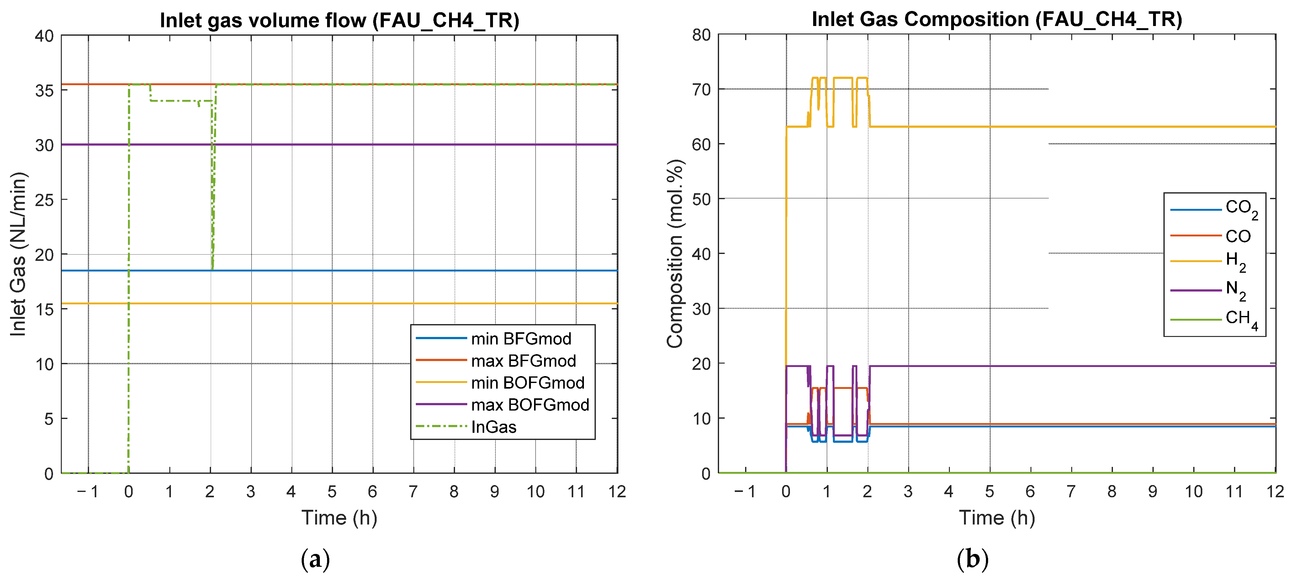
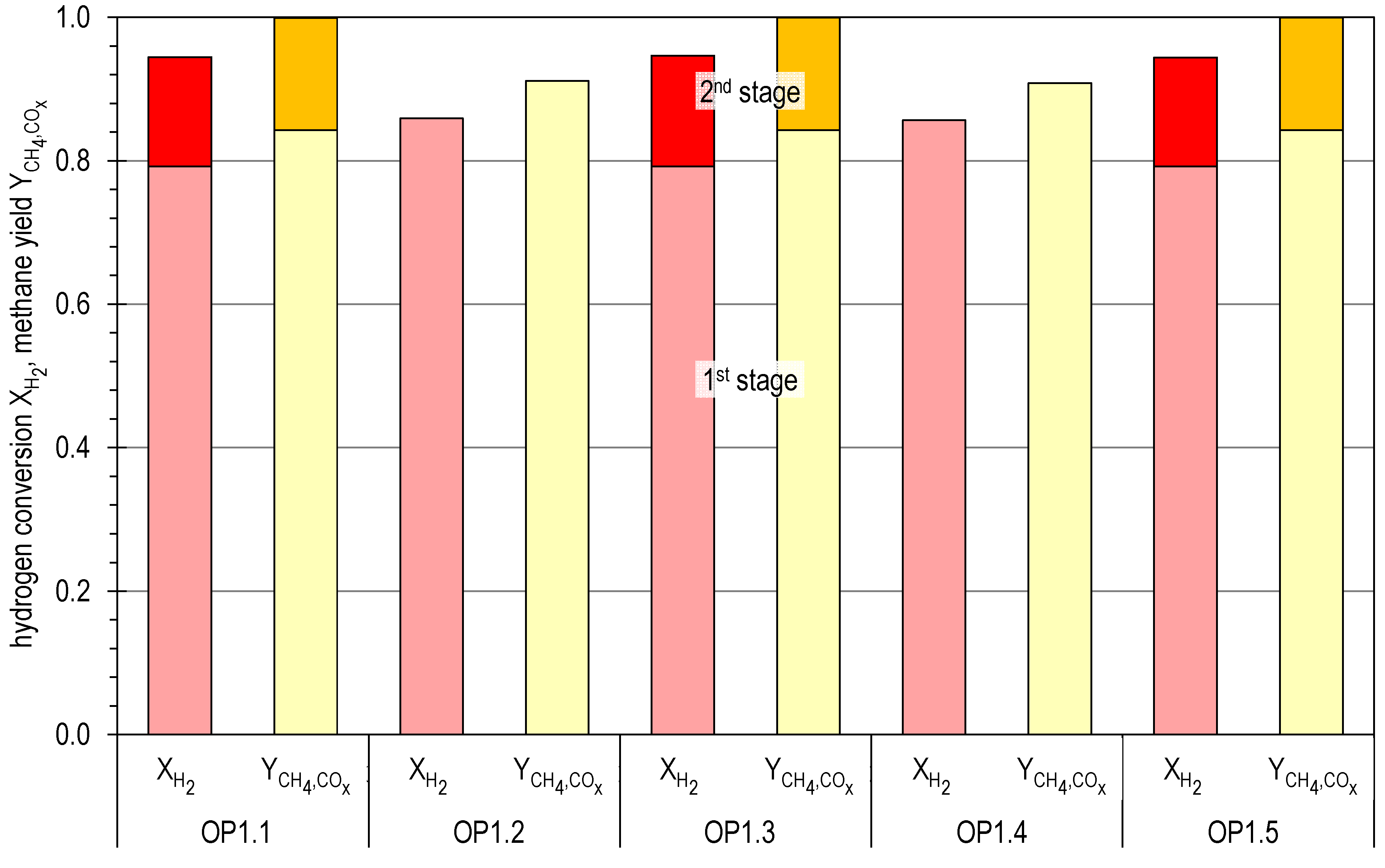
4.2. Results of Experimental Campaign with FAU_CH4_TR
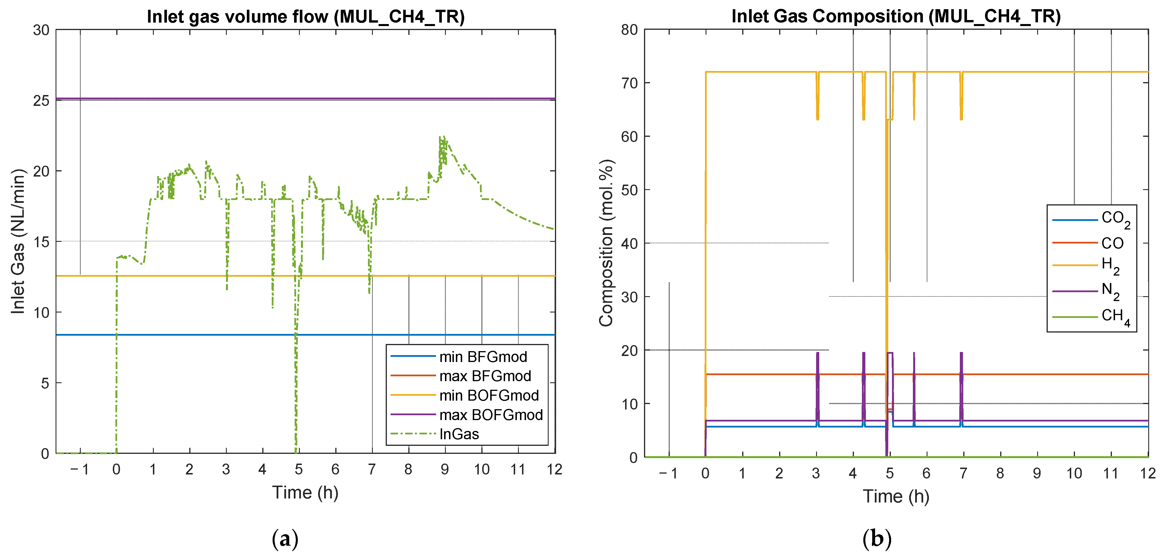
4.3. Results of Experimental Campaign with MUL_CH4_TR
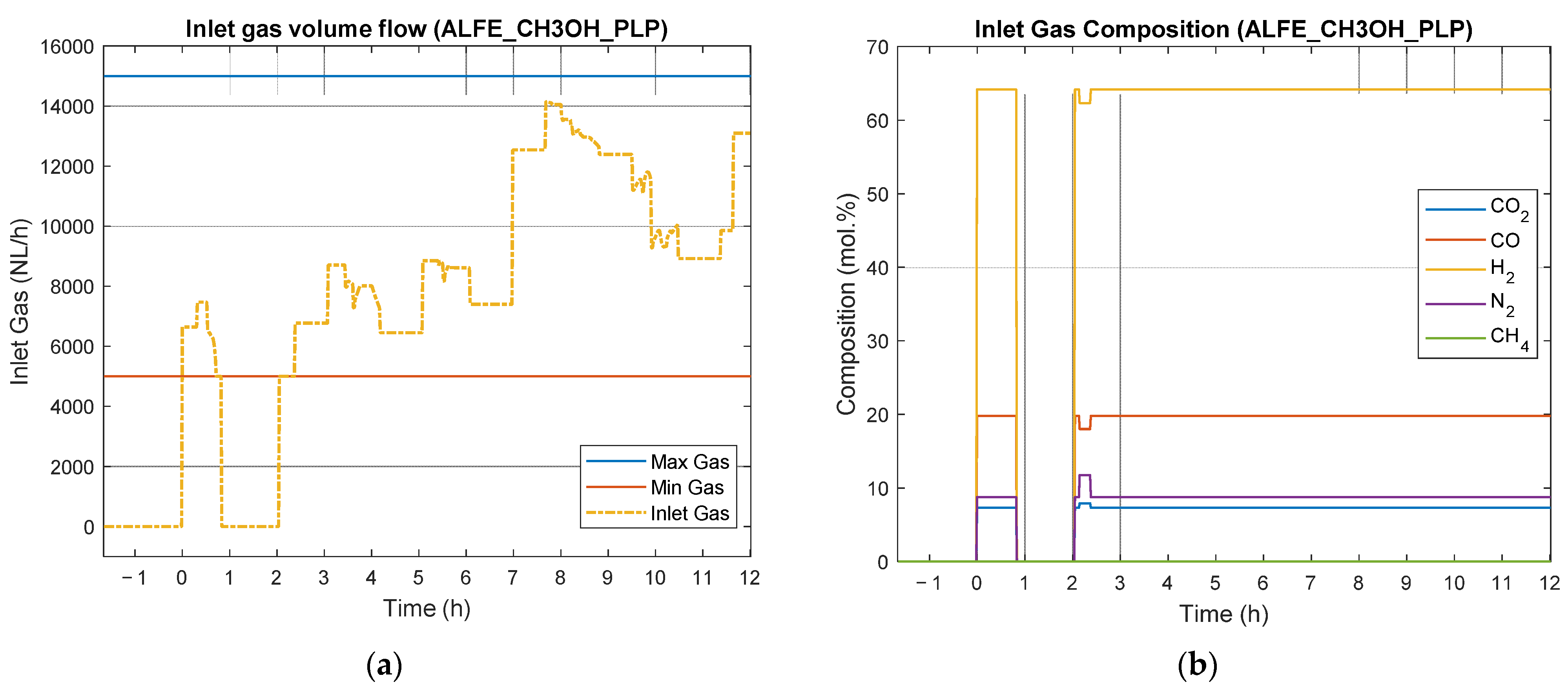
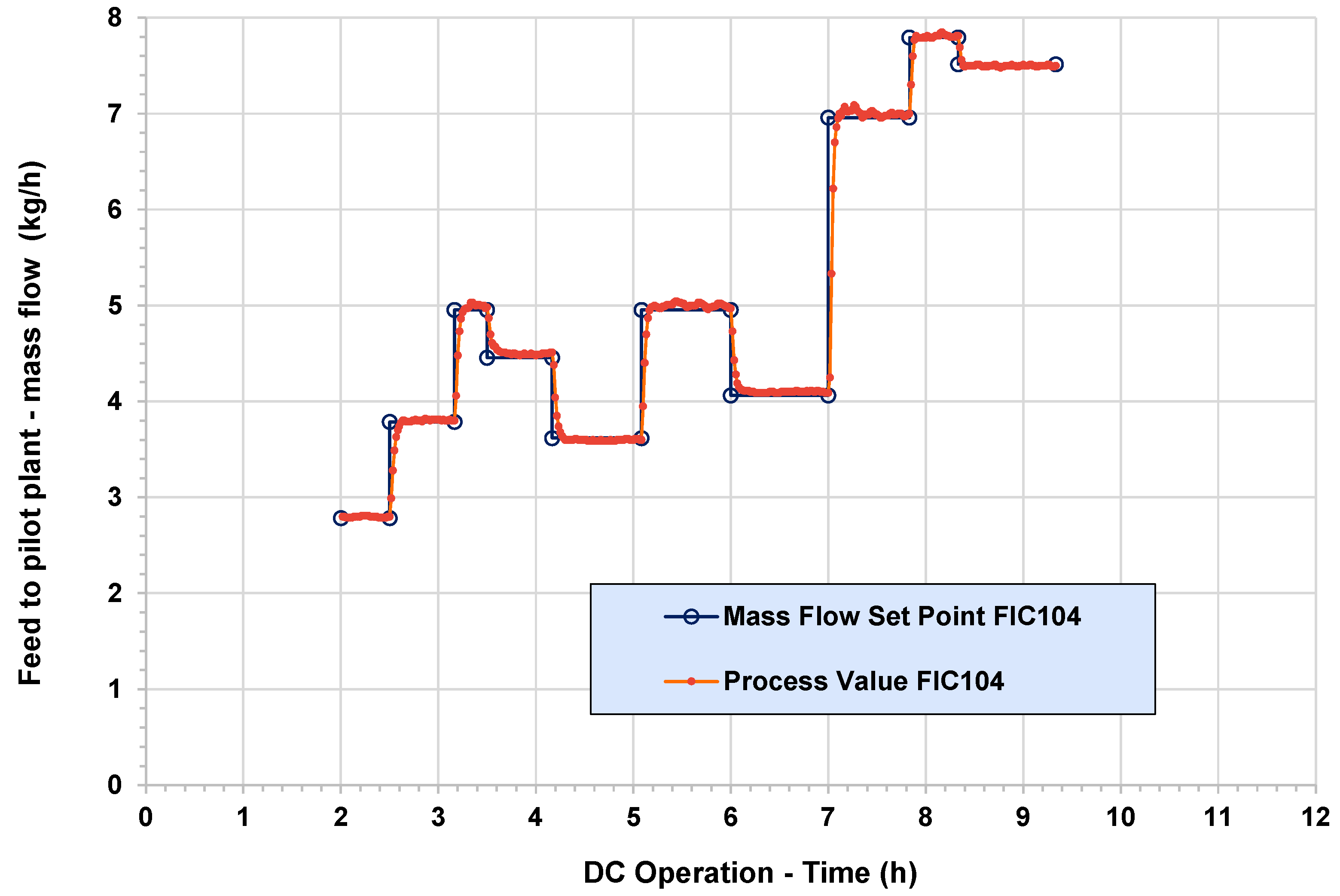
4.4. Results of Experimental Campaign with ALFE_CH3OH_PLP
5. Summary, Conclusions, and Future Works
Author Contributions
Funding

Institutional Review Board Statement
Informed Consent Statement
Data Availability Statement
Conflicts of Interest
References
- European Commission. The European Green Deal; European Commission: Brussels, Belgium, 2019.
- European Commission. “Fit for 55”: Delivering the EU’s 2030 Climate Target on the Way to Climate Neutrality; European Commission: Brussels, Belgium, 2021.
- European Commission. Towards Competitive and Clean European Steel; European Commission: Brussels, Belgium, 2021.
- Estep Clean Steel Partnership. Strategic Research and Innovation Agenda (SRIA); Estep Clean Steel Partnership: Brussels, Belgium, 2021. [Google Scholar]
- Voestalpine Stahl GmbH. Analysenergebnisse Der Umwelt—Und Betriebsanalytik (Durchgeführt Für i3 Upgrade); Technical Report; Voestalpine Stahl GmbH: Linz, Austria, 2019. [Google Scholar]
- Remus, R.; Roudier, S.; Aguado Monsonet, M.A.; Sancho, L.D. Best Available Techniques (BAT) Reference Document for Iron and Steel Production; Publications Office of the European Union: Luxembourg, 2013.
- Schlüter, S.; Hennig, T. Modeling the Catalytic Conversion of Steel Mill Gases Using the Example of Methanol Synthesis. Chem. Ing. Tech. 2018, 90, 1541–1558. [Google Scholar] [CrossRef]
- Razzaq, R.; Li, C.; Zhang, S. Coke oven gas: Availability, properties, purification, and utilization in China. Fuel 2013, 113, 287–299. [Google Scholar] [CrossRef]
- Moral, G.; Ortiz-Imedio, R.; Ortiz, A.; Gorri, D.; Ortiz, I. Hydrogen Recovery from Coke Oven Gas. Comparative Analysis of Technical Alternatives. Ind. Eng. Chem. Res. 2022, 61, 6106–6124. [Google Scholar] [CrossRef] [PubMed]
- Zhang, Q.; Li, Y.; Xu, J.; Jia, G. Carbon element flow analysis and CO2 emission reduction in iron and steel works. J. Clean. Prod. 2018, 172, 709–723. [Google Scholar] [CrossRef]
- Bhaskar, A.; Assadi, M.; Somehsaraei, H.N. Decarbonization of the Iron and Steel Industry with Direct Reduction of Iron Ore with Green Hydrogen. Energies 2020, 13, 758. [Google Scholar] [CrossRef] [Green Version]
- Wang, R.; Zhao, Y.; Babich, A.; Senk, D.; Fan, X. Hydrogen direct reduction (H-DR) in steel industry—An overview of challenges and opportunities. J. Clean. Prod. 2021, 329, 129797. [Google Scholar] [CrossRef]
- Patisson, F.; Mirgaux, O. Hydrogen Ironmaking: How it Works. Metals 2020, 10, 922. [Google Scholar] [CrossRef]
- Porzio, G.F.; Fornai, B.; Amato, A.; Matarese, N.; Vannucci, M.; Chiappelli, L.; Colla, V. Reducing the energy consumption and CO2 emissions of energy intensive industries through decision support systems—An example of application to the steel industry. Appl. Energy 2013, 112, 818–833. [Google Scholar] [CrossRef]
- Porzio, G.F.; Nastasi, G.; Colla, V.; Vannucci, M.; Branca, T.A. Comparison of multi-objective optimization techniques applied to off-gas management within an integrated steelwork. Appl. Energy 2014, 136, 1085–1097. [Google Scholar] [CrossRef]
- Maddaloni, A.; Matino, R.; Matino, I.; Dettori, S.; Zaccara, A.; Colla, V. A quadratic programming model for the optimization of off-gas networks in integrated steelworks. Matér. Tech. 2019, 107, 502. [Google Scholar] [CrossRef]
- Colla, V.; Matino, I.; Dettori, S.; Petrucciani, A.; Zaccara, A.; Weber, V.; Salame, S.; Zapata, N.; Bastida, S.; Wolff, A.; et al. Assessing the efficiency of the off-gas network management in integrated steelworks. Matér. Tech. 2019, 107, 104. [Google Scholar] [CrossRef]
- Matino, I.; Dettori, S.; Castellano, A.; Matino, R.; Mocci, C.; Vannocci, M.; Maddaloni, A.; Colla, V.; Wolff, A. Machine Learning-Based Models for Supporting Optimal Exploitation of Process Off-Gases in Integrated Steelworks. In Proceedings of the Cybersecurity Workshop by European Steel Technology Platform, ESTEP 2020: Impact and Opportunities of Artificial Intelligence Techniques in the Steel Industry, Pisa, Italy, 15–16 October 2020; Springer: Cham, Switzerland, 2020; pp. 104–118. [Google Scholar]
- Dettori, S.; Matino, I.; Colla, V.; Speets, R. A Deep Learning-Based Approach for Forecasting off-Gas Production and Consumption in the Blast Furnace. Neural Comput. Appl. 2022, 34, 911–923. [Google Scholar] [CrossRef] [PubMed]
- Dettori, S.; Matino, I.; Colla, V.; Weber, V.; Salame, S. Neural Network-based modeling methodologies for energy transformation equipment in integrated steelworks processes. Energy Procedia 2019, 158, 4061–4066. [Google Scholar] [CrossRef]
- Matino, I.; Dettori, S.; Colla, V.; Weber, V.; Salame, S. Forecasting blast furnace gas production and demand through echo state neural network-based models: Pave the way to off-gas optimized management. Appl. Energy 2019, 253, 113578. [Google Scholar] [CrossRef]
- Rieger, J.; Colla, V.; Matino, I.; Branca, T.; Stubbe, G.; Panizza, A.; Brondi, C.; Falsafi, M.; Hage, J.; Wang, X.; et al. Residue Valorization in the Iron and Steel Industries: Sustainable Solutions for a Cleaner and More Competitive Future Europe. Metals 2021, 11, 1202. [Google Scholar] [CrossRef]
- Chisalita, D.-A.; Petrescu, L.; Cobden, P.; van Dijk, H.; Cormos, A.-M.; Cormos, C.-C. Assessing the environmental impact of an integrated steel mill with post-combustion CO2 capture and storage using the LCA methodology. J. Clean. Prod. 2018, 211, 1015–1025. [Google Scholar] [CrossRef]
- Huang, Z.; Ding, X.; Sun, H.; Liu, S. Identification of main influencing factors of life cycle CO2 emissions from the integrated steelworks using sensitivity analysis. J. Clean. Prod. 2010, 18, 1052–1058. [Google Scholar] [CrossRef]
- Saima, W.H.; Mogi, Y.; Haraoka, T. Development of PSA System for the Recovery of Carbon Dioxide and Carbon Monoxide from Blast Furnace Gas in Steel Works. Energy Procedia 2013, 37, 7152–7159. [Google Scholar] [CrossRef]
- Steynberg, A. Chapter 1—Introduction to Fischer-Tropsch Technology. In Studies in Surface Science and Catalysis; Steynberg, A., Dry, M., Eds.; Elsevier: Amsterdam, The Netherlands, 2004; Volume 152, pp. 1–63. [Google Scholar]
- Valera-Medina, A.; Roldan, A. Ammonia from Steelworks. In Sustainable Ammonia Production. Green Energy and Technology; Inamuddin, Boddula, R., Asiri, A., Eds.; Springer: Cham, Switzerland, 2020; pp. 69–80. [Google Scholar]
- De Ras, K.; Van De Vijver, R.; Galvita, V.V.; Marin, G.B.; Van Geem, K.M. Carbon capture and utilization in the steel industry: Challenges and opportunities for chemical engineering. Curr. Opin. Chem. Eng. 2019, 26, 81–87. [Google Scholar] [CrossRef]
- Lyke, S.E.; Moore, R.H. Chemical Production from Industrial By-Product Gases: Final Report; Battelle Pacific Northwest Labs: Richland, WA, USA, 1981.
- Cordier, J.; Dussart, B. Ammonia and Methanol Production—How Savings Can Be Made. Pet. Technol. 1984, 307, 38–45. [Google Scholar]
- Kim, S.; Kim, J. The optimal carbon and hydrogen balance for methanol production from coke oven gas and Linz-Donawitz gas: Process development and techno-economic analysis. Fuel 2020, 266, 117093. [Google Scholar] [CrossRef]
- Deng, L.; Ii, T.A.A. Techno-economic analysis of coke oven gas and blast furnace gas to methanol process with carbon dioxide capture and utilization. Energy Convers. Manag. 2019, 204, 112315. [Google Scholar] [CrossRef]
- Kim, D.; Han, J. Techno-economic and climate impact analysis of carbon utilization process for methanol production from blast furnace gas over Cu/ZnO/Al2O3 catalyst. Energy 2020, 198, 117355. [Google Scholar] [CrossRef]
- Lundgren, J.; Ekbom, T.; Hulteberg, C.; Larsson, M.; Grip, C.-E.; Nilsson, L.; Tunå, P. Methanol production from steel-work off-gases and biomass based synthesis gas. Appl. Energy 2013, 112, 431–439. [Google Scholar] [CrossRef] [Green Version]
- Haag, S.; Castillo-Welter, F.; Schuhmann, T.; Williams, B.A.; Oelmann, T.; Günther, A.; Gorny, M. How to Convert CO2 to Green Methanol. In Proceedings of the Challenges for Petrochemicals and Fuels: Integration of Value Chains and Energy Transition (DGMK Conference), Berlin, Germany, 10–12 October 2018. [Google Scholar]
- Oelmann, T.; Gorny, M.; Schuhmann, T.; Strozyk, M.; Castillo-Welter, F.; Drosdzol, C.; Haag, S. A New Reactor Concept for Conversion of CO2 to Methanol. Oil Gas-Eur. Mag. 2021, 47, 28–32. [Google Scholar]
- Girod, K.; Lohmann, H.; Schlüter, S.; Kaluza, S. Methanol Synthesis with Steel-Mill Gases: Simulation and Practical Testing of Selected Gas Utilization Scenarios. Processes 2020, 8, 1673. [Google Scholar] [CrossRef]
- Girod, K.; Breitkreuz, K.; Hennig, T.; Lohmann, H.; Kaluza, S.; Schlüter, S. Steel Mills as Syngas Source for Methanol Synthesis: Simulation and Practical Performance Investigations. Chem. Eng. Trans. 2019, 74, 475–480. [Google Scholar]
- Periodic Reporting for Period 3—FReSMe (From Residual Steel Gasses to Methanol)|H2020|CORDIS|European Com-Mission. Available online: https://cordis.europa.eu/project/id/727504/reporting (accessed on 9 June 2022).
- Lee, J.-K.; Lee, I.-B.; Han, J. Techno-economic analysis of methanol production from joint feedstock of coke oven gas and basic oxygen furnace gas from steel-making. J. Ind. Eng. Chem. 2019, 75, 77–85. [Google Scholar] [CrossRef]
- Thonemann, N.; Maga, D. Life Cycle Assessment of Steel Mill Gas-Based Methanol Production within the Carbon2Chem® Project. Chem. Ing. Tech. 2020, 92, 1425–1430. [Google Scholar] [CrossRef]
- Rigamonti, L.; Brivio, E. Life cycle assessment of methanol production by a carbon capture and utilization technology applied to steel mill gases. Int. J. Greenh. Gas Control 2022, 115, 103616. [Google Scholar] [CrossRef]
- Müller, K.; Rachow, F.; Günther, V.; Schmeisser, D. Methanation of Coke Oven Gas with Nickel-Based Catalysts. J. Environ. Sci. 2019, 4, 73–79. [Google Scholar]
- Razzaq, R.; Zhu, H.; Jiang, L.; Muhammad, U.; Li, C.; Zhang, S. Catalytic Methanation of CO and CO2 in Coke Oven Gas over Ni–Co/ZrO2–CeO2. Ind. Eng. Chem. Res. 2013, 52, 2247–2256. [Google Scholar] [CrossRef]
- Rosenfeld, D.C.; Böhm, H.; Lindorfer, J.; Lehner, M. Scenario analysis of implementing a power-to-gas and biomass gasification system in an integrated steel plant: A techno-economic and environmental study. Renew. Energy 2019, 147, 1511–1524. [Google Scholar] [CrossRef]
- Perpiñán, J.; Bailera, M.; Romeo, L.M.; Peña, B.; Eveloy, V. CO2 Recycling in the Iron and Steel Industry via Power-to-Gas and Oxy-Fuel Combustion. Energies 2021, 14, 7090. [Google Scholar] [CrossRef]
- Wolf-Zoellner, P.; Medved, A.R.; Lehner, M.; Kieberger, N.; Rechberger, K. In Situ Catalytic Methanation of Real Steelworks Gases. Energies 2021, 14, 8131. [Google Scholar] [CrossRef]
- Hauser, A.; Weitzer, M.; Gunsch, S.; Neubert, M.; Karl, J. Dynamic hydrogen-intensified methanation of synthetic by-product gases from steelworks. Fuel Process. Technol. 2021, 217, 106701. [Google Scholar] [CrossRef]
- Zaccara, A.; Petrucciani, A.; Matino, I.; Branca, T.A.; Dettori, S.; Iannino, V.; Colla, V.; Bampaou, M.; Panopoulos, K. Renewable Hydrogen Production Processes for the Off-Gas Valorization in Integrated Steelworks through Hydrogen Intensified Methane and Methanol Syntheses. Metals 2020, 10, 1535. [Google Scholar] [CrossRef]
- Bampaou, M.; Panopoulos, K.; Seferlis, P.; Voutetakis, S.; Matino, I.; Petrucciani, A.; Zaccara, A.; Colla, V.; Dettori, S.; Branca, T.A.; et al. Integration of Renewable Hydrogen Production in Steelworks Off-Gases for the Synthesis of Methanol and Methane. Energies 2021, 14, 2904. [Google Scholar] [CrossRef]
- Kolb, S.; Plankenbühler, T.; Hofmann, K.; Bergerson, J.; Karl, J. Life cycle greenhouse gas emissions of renewable gas technologies: A comparative review. Renew. Sustain. Energy Rev. 2021, 146, 111147. [Google Scholar] [CrossRef]
- Lee, J.H. Model predictive control: Review of the three decades of development. Int. J. Control Autom. Syst. 2011, 9, 415–424. [Google Scholar] [CrossRef]
- Neubert, M.; Hauser, A.; Pourhossein, B.; Dillig, M.; Karl, J. Experimental evaluation of a heat pipe cooled structured reactor as part of a two-stage catalytic methanation process in power-to-gas applications. Appl. Energy 2018, 229, 289–298. [Google Scholar] [CrossRef]
- Biegger, P.; Kirchbacher, F.; Medved, A.R.; Miltner, M.; Lehner, M.; Harasek, M. Development of Honeycomb Methanation Catalyst and Its Application in Power to Gas Systems. Energies 2018, 11, 1679. [Google Scholar] [CrossRef] [Green Version]
- e Silva, D.P.; Salles, J.L.F.; Fardin, J.F.; Pereira, M.M.R. Management of an island and grid-connected microgrid using hybrid economic model predictive control with weather data. Appl. Energy 2020, 278, 115581. [Google Scholar] [CrossRef]
- Dettori, S.; Matino, I.; Iannino, V.; Colla, V.; Hauser, A.; Wolf-Zöllner, P.; Haag, S. Optimizing methane and methanol production from integrated steelworks process off-gases through economic hybrid model predictive control. IFAC-PapersOnLine 2022, 55, 66–71. [Google Scholar] [CrossRef]
- Bampaou, M.; Kyriakides, A.S.; Panopoulos, K.; Seferlis, P.; Voutetakis, S. Modelling of Methanol Synthesis: Improving Hydrogen Utilisation. Chem. Eng. Trans. 2021, 88, 931–936. [Google Scholar] [CrossRef]
- Matino, I.; Dettori, S.; Colla, V.; Rechberger, K.; Kieberger, N. Echo-state neural networks forecasting steelworks off-gases for their dispatching in CH4 and CH3OH syntheses reactors. In Proceedings of the 29th European Symposium on Artificial Neural Networks, Computational Intelligence and Machine Learning, Online Conference, 6–8 October 2021. [Google Scholar] [CrossRef]
- Matino, I.; Dettori, S.; Zaccara, A.; Petrucciani, A.; Iannino, V.; Colla, V.; Bampaou, M.; Panopoulos, K.; Rechberger, K.; Kolb, S.; et al. Hydrogen role in the valorization of integrated steelworks process off-gases through methane and methanol syntheses. Matériaux Tech. 2021, 109, 308. [Google Scholar] [CrossRef]
- Medved, A.R.; Lehner, M.; Rosenfeld, D.C.; Lindorfer, J.; Rechberger, K. Enrichment of Integrated Steel Plant Process Gases with Implementation of Renewable Energy: Integration of Power-to-Gas and Biomass Gasification System in Steel Production. Johns. Matthey Technol. Rev. 2021, 65, 453–465. [Google Scholar] [CrossRef]


| Compound/Feature | Unit | COG b,c | BFG c | BOFG c |
|---|---|---|---|---|
| N2 | mol.% | 2.9 | 48.3 | 27.6 |
| CO2 | mol.% | 1.2 | 23.1 | 20.0 |
| CO | mol.% | 5.8 | 24.9 | 51.8 |
| H2 | mol.% | 65.7 c | 3.7 | 0.6 |
| CH4 | mol.% | 21.8 | traces | - |
| CnHm | mol.% | 2.5 | traces | - |
| O2 | mol.% | 0.1 | traces | traces |
| NCV a | kWh/Nm3 | 5.9 | 1.0 | 2.4 |
| Other features | - | Significant content of minor compounds (i.e., potential catalyst poisons) | Continuously produced | Discontinuously produced |
| Main users (in decreasing order) | - | Power plant, hot rolling mill, mixing and enrichment station, coke plant area, plate annealing, blast furnace area | Mixing and enrichment station d, blast furnace area | Mixing and enrichment station d |
| Operating Point | H2 | CO2 | CO | CH4 | N2 | SNCH4 | Psyn | |
|---|---|---|---|---|---|---|---|---|
| NL/min | mol.% | mol.% | mol.% | mol.% | mol.% | - | kW | |
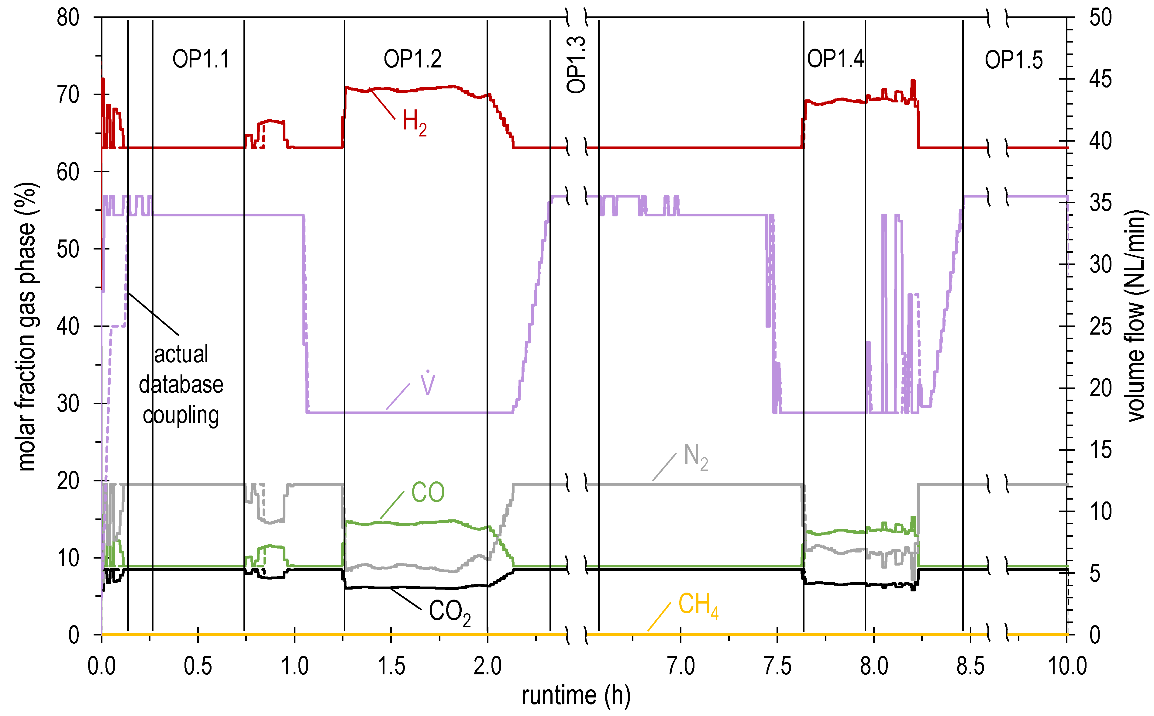
| OP1.1 | 34.0 | 63.1 | 8.5 | 8.9 | 0.0 | 19.5 | 1.04 | 4.39 |
| OP1.2 | 18.0 | 70.5 | 6.2 | 14.4 | 0.0 | 8.9 | 1.04 | 2.71 |
| OP1.3 | 35.5 | 63.1 | 8.5 | 8.9 | 0.0 | 19.5 | 1.04 | 4.59 |
| OP1.4 | 18.0 | 69.0 | 6.6 | 13.3 | 0.0 | 11.0 | 1.04 | 2.65 |
| OP1.5 | 35.5 | 63.1 | 8.5 | 8.9 | 0.0 | 19.5 | 1.04 | 4.59 |
| OP2.1 | 35.5 | 63.1 | 8.5 | 8.9 | 0.0 | 19.5 | 1.04 | 4.59 |
| Operating Point | GHSV | H2 | CO2 | CO | CH4 | N2 | XCOx | |
|---|---|---|---|---|---|---|---|---|
| NL/min | h−1 | mol.% | mol.% | mol.% | mol.% | mol.% | % | |
| 1 | 13.9 | 3300 | 13.4 | 0.3 | 0.0 | 65.7 | 20.6 | 99.6 |
| 2 | 13.6 | 3200 | 12.7 | 0.3 | 0.0 | 65.7 | 21.3 | 99.6 |
| 3 | 17.9 | 4300 | 12.8 | 0.6 | 0.0 | 70.1 | 16.5 | 99.2 |
| 4 | 20.2 | 4800 | 13.3 | 1.0 | 0.0 | 67.2 | 18.6 | 98.7 |
| 5 | 18.0 | 4300 | 12.9 | 0.8 | 0.0 | 68.0 | 18.4 | 98.9 |
| 6 | 19.6 | 4700 | 13.7 | 0.9 | 0.0 | 66.9 | 18.5 | 98.7 |
| 7 * | 18.0 | 3200 | 16.8 | 0.3 | 0.0 | 46.4 | 36.6 | 99.5 |
| 8 | 18.0 | 4300 | 13.2 | 0.8 | 0.0 | 67.8 | 18.2 | 98.9 |
| 9 * | 18.0 | 3200 | 17.8 | 0.2 | 0.0 | 46.3 | 35.7 | 99.6 |
| 10 * | 12.3 | 2100 | 13.9 | 0.2 | 0.0 | 43.0 | 43.0 | 99.7 |
| 11 | 18.0 | 4300 | 13.3 | 0.8 | 0.0 | 67.9 | 18.1 | 98.9 |
| 12 | 15.9 | 3800 | 13.2 | 0.6 | 0.0 | 68.3 | 17.9 | 99.2 |
| 13 * | 16.3 | 2700 | 19.9 | 0.2 | 0.0 | 51.1 | 28.9 | 99.8 |
| 14 | 18.0 | 4300 | 13.6 | 0.7 | 0.0 | 67.6 | 18.1 | 99.0 |
| 15 | 22.5 | 5400 | 15.4 | 1.2 | 0.0 | 65.2 | 18.2 | 98.3 |
| 16 | 19.3 | 4600 | 14.2 | 0.8 | 0.0 | 66.9 | 18.1 | 98.8 |
| Time of Sampling | p | T | Tmax | Feed | XCO2 | XCO | XH2 | Raw CH3OH |
|---|---|---|---|---|---|---|---|---|
| hours | bar | °C | °C | NL/h (kg/h) | % | % | % | kg/h |
| 2.00 (start of operation) | 80 | 220 | 278 | 4927 (2.80) | 77.8 | 99.6 | 82.5 | 2.06 |
| 2.80 | 80 | 220 | 272 | 6530 (3.71) | 77.3 | 99.6 | 79.7 | 2.72 |
| 3.30 | 80 | 220 | 269 | 8441 (4.79) | 77.7 | 99.6 | 80.2 | 3.52 |
| 3.80 | 80 | 220 | 269 | 8000 (4.54) | 76.4 | 99.6 | 79.2 | 3.32 |
| 4.50 | 80 | 220 | 272 | 6459 (3.66) | 76.3 | 99.6 | 81.1 | 2.67 |
| 5.30 | 80 | 220 | 269 | 8663 (4.91) | 75.0 | 99.5 | 78.8 | 3.56 |
| 6.30 | 80 | 230 | 280 | 7323 (4.15) | 74.3 | 99.4 | 79.2 | 2.99 |
| 7.30 | 80 | 230 | 273 | 11,945 (6.78) | 72.6 | 99.2 | 77.6 | 4.85 |
| 8.00 | 80 | 230 | 271 | 13,618 (7.73) | 70.5 | 99.1 | 77.0 | 5.47 |
| 9.50 (end of operation) | 80 | 230 | 271 | 13,265 (7.52) | 70.4 | 99.1 | 78.3 | 5.32 |
| Time of Sampling | p | T | Tmax | Feed | Raw CH3OH | Water in Raw CH3OH | Total By-Products |
|---|---|---|---|---|---|---|---|
| hours | bar | °C | °C | NL/h (kg/h) | kg/h | % | wt.ppm |
| 2.00 (start of operation) | 80 | 220 | 278 | 4927 (2.80) | 2.06 | 11.8 | 4680 |
| 9.50 (end of operation) | 80 | 230 | 271 | 13,265 (7.52) | 5.32 | 10.9 | 4460 |
| Stage | Feed Inlet | Tinlet | Tmax | XCO2 | XCO | XH2 | By-Products in Raw MeOH | Water in Raw MeOH |
|---|---|---|---|---|---|---|---|---|
| - | NL/h | °C | °C | % | % | % | wt.ppm | wt.% |
| 1 | 4927 | 220 | 278 | 16.9 | 93.0 | 56.9 | 6450 | 3.2 |
| 2 | 2132 | 220 | 226 | 40.3 | 84.4 | 29.5 | 671 | 27.5 |
| 3 | 1557 | 220 | 224 | 50.9 | 52.1 | 24.1 | 396 | 35.6 |
| 4 | 1236 | 220 | 224 | 60.0 | 41.1 | 21.6 | 339 | 35.7 |
| Overall Plant | 4927 | 220 | 278 | 77.8 | 99.6 | 82.5 | 4680 | 11.8 |
| Stage | Feed Inlet | Tinlet | Tmax | XCO2 | XCO | XH2 | By-Products in Raw MeOH | Water in Raw MeOH |
|---|---|---|---|---|---|---|---|---|
| NL/h | °C | °C | % | % | % | wt.ppm | wt.% | |
| 1 | 13,265 | 230 | 271 | 13.1 | 82.3 | 49.7 | 6463 | 2.5 |
| 2 | 6656 | 230 | 243 | 26.9 | 82.1 | 29.3 | 1258 | 17.2 |
| 3 | 4802 | 230 | 236 | 38.9 | 58.0 | 22.4 | 519 | 32.8 |
| 4 | 3854 | 230 | 236 | 47.0 | 44.7 | 20.0 | 387 | 35.4 |
| Overall Plant | 13,265 | 230 | 271 | 70.4 | 99.1 | 78.3 | 4460 | 10.9 |
Publisher’s Note: MDPI stays neutral with regard to jurisdictional claims in published maps and institutional affiliations. |
© 2022 by the authors. Licensee MDPI, Basel, Switzerland. This article is an open access article distributed under the terms and conditions of the Creative Commons Attribution (CC BY) license (https://creativecommons.org/licenses/by/4.0/).
Share and Cite
Hauser, A.; Wolf-Zoellner, P.; Haag, S.; Dettori, S.; Tang, X.; Mighani, M.; Matino, I.; Mocci, C.; Colla, V.; Kolb, S.; et al. Valorizing Steelworks Gases by Coupling Novel Methane and Methanol Synthesis Reactors with an Economic Hybrid Model Predictive Controller. Metals 2022, 12, 1023. https://doi.org/10.3390/met12061023
Hauser A, Wolf-Zoellner P, Haag S, Dettori S, Tang X, Mighani M, Matino I, Mocci C, Colla V, Kolb S, et al. Valorizing Steelworks Gases by Coupling Novel Methane and Methanol Synthesis Reactors with an Economic Hybrid Model Predictive Controller. Metals. 2022; 12(6):1023. https://doi.org/10.3390/met12061023
Chicago/Turabian StyleHauser, Alexander, Philipp Wolf-Zoellner, Stéphane Haag, Stefano Dettori, Xiaoliang Tang, Moein Mighani, Ismael Matino, Claudio Mocci, Valentina Colla, Sebastian Kolb, and et al. 2022. "Valorizing Steelworks Gases by Coupling Novel Methane and Methanol Synthesis Reactors with an Economic Hybrid Model Predictive Controller" Metals 12, no. 6: 1023. https://doi.org/10.3390/met12061023
APA StyleHauser, A., Wolf-Zoellner, P., Haag, S., Dettori, S., Tang, X., Mighani, M., Matino, I., Mocci, C., Colla, V., Kolb, S., Bampaou, M., Panopoulos, K., Kieberger, N., Rechberger, K., & Karl, J. (2022). Valorizing Steelworks Gases by Coupling Novel Methane and Methanol Synthesis Reactors with an Economic Hybrid Model Predictive Controller. Metals, 12(6), 1023. https://doi.org/10.3390/met12061023