1. Introduction
Nitriding is a well-established thermochemical surface treatment to improve the surface properties of steels. Classically, it is used to increase corrosion resistance by the formation of nitriding layers and to enhance the wear properties by significantly increasing the surface hardness [
1,
2,
3,
4]. The most commonly used nitriding techniques are salt bath nitriding, gas nitriding, and plasma nitriding. In comparison to salt bath and gas nitriding, the main advantage of plasma nitriding is the variability in the process control for adjusting the properties of the nitrided zone [
5,
6,
7,
8]. During plasma nitriding, molecular nitrogen is dissociated and activated by a plasma in a nitrogen–hydrogen atmosphere, which enables the diffusion of nitrogen into the material surface [
9]. This nitrogen can generate a nitrided zone consisting of a compound layer (CL) on the surface and beneath a diffusion layer (DL) that grows into the material. The compound layer consists of
and
nitrides [
7,
10,
11,
12,
13]. In contrast to the CL, which mainly consists of iron nitrides, the DL is characterized by an incomplete transformation of the base material and consists of nitride precipitations, mainly of the nitride forming alloying elements (e.g., Cr, Mo, Al, Ti), and dissolved nitrogen. The resulting nitride phases are characterized by a strongly increased hardness and brittleness, where the mechanical properties are different for the several nitrides [
14].
As already mentioned, the properties of the nitride zone are strongly influenced by the applied process parameters during plasma nitriding and the chemical composition of the steel. The most important process parameters are the process temperature and the process duration, as well as the composition of the gas mixture. For example, the formation of a compound layer can be prevented by an appropriate gas composition. The process temperature affects the layer growth and the structure of the CL and DL. With increasing temperature, the resulting layer thickness of the CL and DL increases due to accelerated nitrogen diffusion at higher temperatures [
15,
16,
17,
18]. Furthermore, at lower process temperatures (400 °C–500 °C), the volume fraction of
-nitrides within the compound layer predominates, but with increasing process temperature, the content of
-nitrides becomes more dominant. The decrease in hardness at the material surface with increasing temperature is caused by the declining content of
-nitride [
19,
20,
21]. With increasing nitriding time/duration, in turn, the amount of nitrogen in the process atmosphere increases, allowing more nitrides to be formed [
19,
22]. Therefore, the nitrided zone thickness and micro hardness are enhanced. Further the volume fraction of
-nitrides at the CL decreases, while the fraction of
-nitrides increases [
17,
20,
22]. Independent of the process temperature and duration, it is also possible to increase nitride formation based on the gas mixture by increasing the proportion of N
2 so that more nitrogen is available for diffusion [
17]. In addition to the process parameters, the material composition exerts a significant influence on the layer formation and the resulting properties [
23,
24]. This is illustrated by a prediction tool (developed in collaboration between the FraunhoferInstitute for Surface Engineering and Thin Films (IST) and the Institute of Materials Science and Engineering at Chemnitz University of Technology (IWW)) [
25], which calculates different hardness curves for different steels as a function of temperature, treatment time, and nitrogen content. For example, chromium contributes to a significant increase in hardness by the formation of chromium nitrides in near-surface areas. Furthermore, alloying elements hinder the diffusion of nitrogen, which reduces the nitriding depth. The additional alloying elements bind nitrogen by forming different nitride precipitations, e.g., Cr, Mo, Ti, and Al nitrides, which thereby decrease the amount of diffusible species [
26,
27]. Other elements do not form nitrides and, yet, massively inhibit the diffusion of nitrogen, such as nickel [
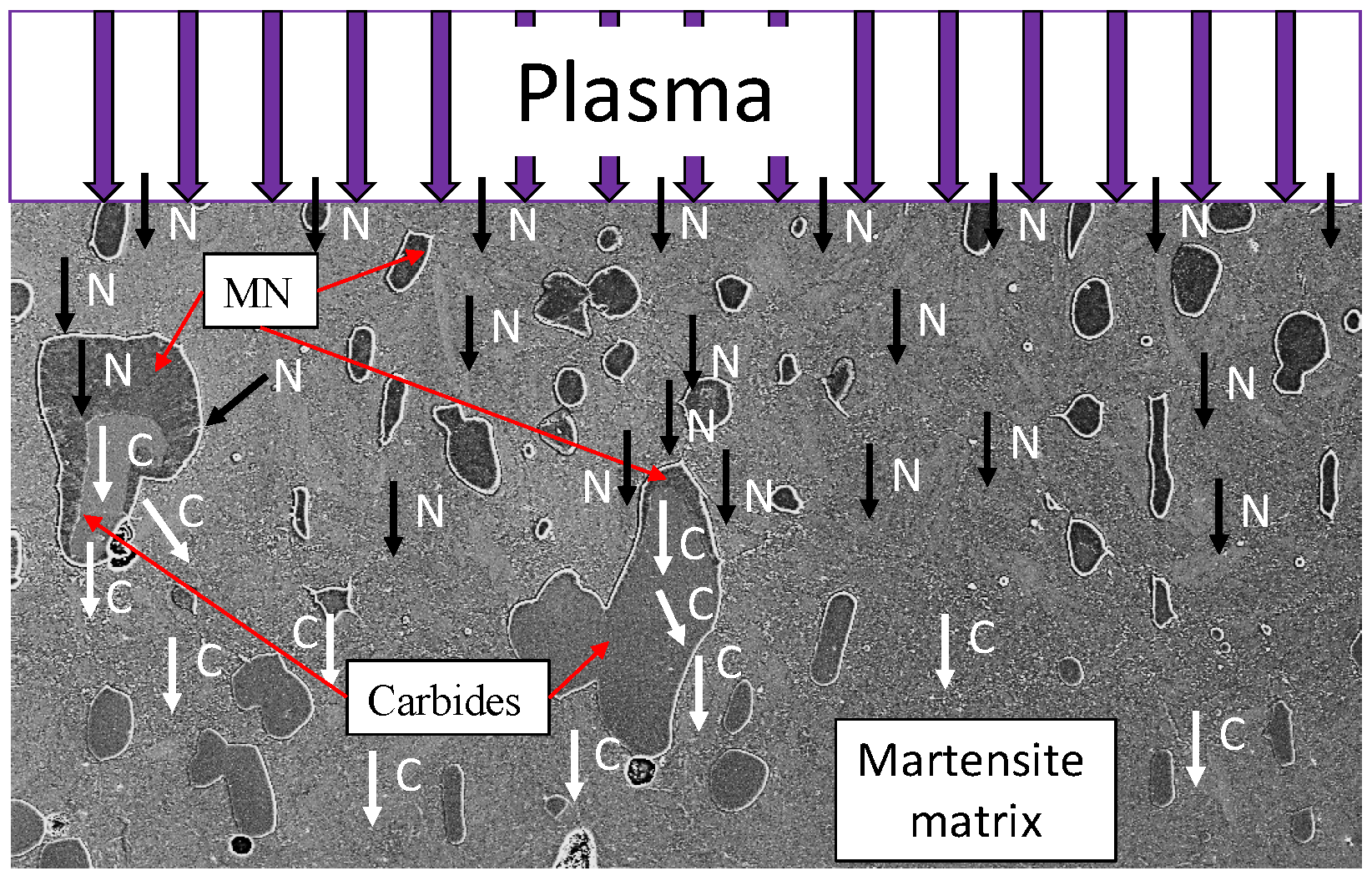
27]. In high-alloy tool steels, large primary carbides often occur in addition to the finely-dispersed precipitates. These primary carbides are also affected by the nitriding process. Garzón et al. [
28] investigated the role of primary chromium carbides (M
7C
3) during plasma nitriding of the tool steel AISI D2. They observed the dissolution of chromium carbides and a subsequent diffusion-controlled local precipitation of chromium nitrides (CrN or generally as metal nitride (MN)). The evolution of atomic partitioning during this phase transformation was shown in [
28] in a schematic model; compare
Figure 1. This illustrates that the carbides and MN influence the nitrogen diffusion. In [
28], it was reported that MN formation with low carbon dissolution, as well as negligible accumulation of nitrogen inside the M
7C
3 carbides has been observed.
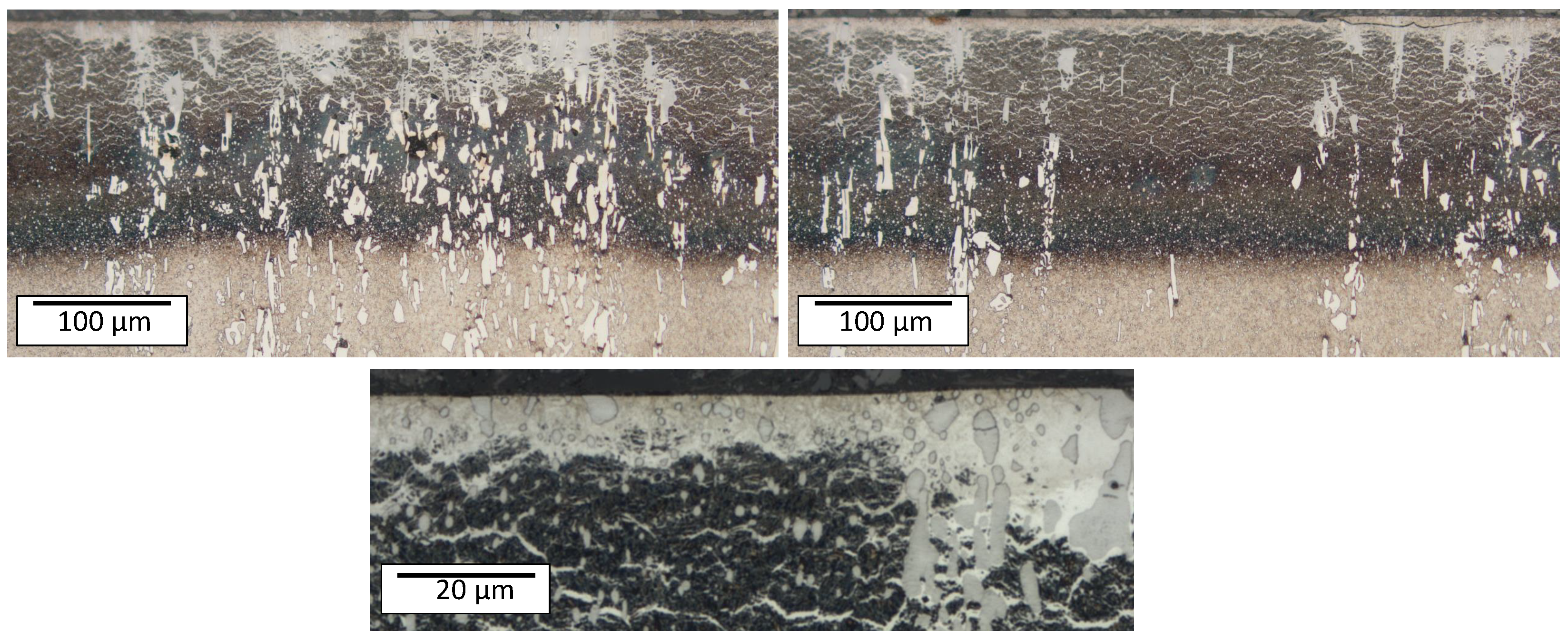
The influence of the microstructure and in particular of the primary carbides becomes very clear in a comparison between an area with and without large primary carbides of the high-alloy tool steel X153CrMoV12; see
Figure 2. The compound and diffusion layer thicknesses are recognizably heterogeneous.
In plasma nitriding, the parameters are adjustable in a wide range, but the resulting diffusion process, especially for high-alloy tool steels, is still relatively unexplored. However, in order to be able to selectively adjust the hardness and the layer properties, more in-depth knowledge of the diffusion process of N and the interactions of carbides and nitrides is required. Therefore, a detailed study of the relevant process parameters temperature and duration was conducted on the high-alloy tool steel X153CrMoV12 (corresponding to AISI D2), which tends to form chromium carbides. Furthermore, an FE model for a qualitative analysis of the influence of chromium carbides on the nitrogen diffusion and nitride formation is developed. This FE model can be used to understand the underlying diffusion mechanisms and to tailor the nitrided zone for specific technical applications. In particular, the interactions during the diffusion processes between the matrix, compound layer, and chromium carbides can be taken into account for the first time using FEM.
3. Results and Discussion
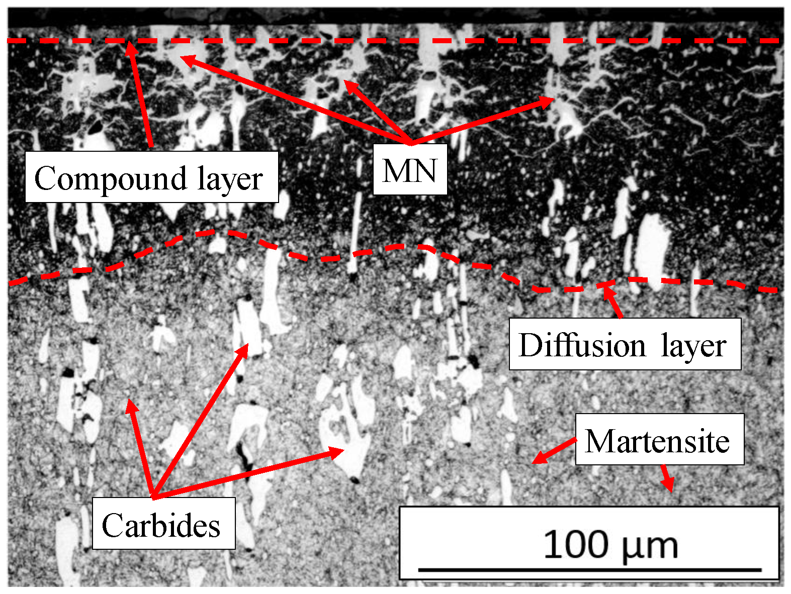
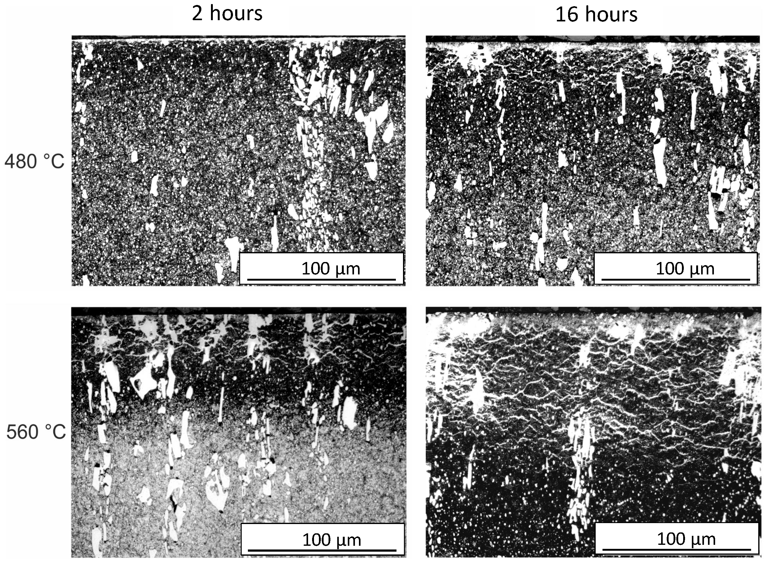
Figure 6 illustrates the typical phases after plasma nitriding. The compound layer (CL) on the surface, the metal nitrides (MNs), and the diffusion layer (DL) can be seen. The heterogeneous course of the diffusion layer is obvious. The initial microstructure consisting of tempered martensite/ferrite and carbides is recognizable in the lower area. The microstructure obtained after plasma nitriding at different temperatures and times is shown in
Figure 7. It can be seen that with increasing plasma nitriding temperature and duration, the layer thicknesses increase. At the same time, a network is increasingly formed, which is referred to as a cementite network in [
37,
38] and is formed by carbon displacement due to nitrogen diffusion. These precipitations of a second phase take place mainly at the end of the strongly nitrided region towards the sample core, and this corresponds to the area where carbon enrichment is present [
28]. According to [
27], especially at higher carbon and chromium contents, part of the carbon accumulates in front of the diffusion front. In addition, depending on the alloy composition of the base metal and the nitriding conditions, the majority of the carbon released by nitride formation diffuses towards the surface due to the strong decarburizing effect of the nitriding medium and the higher diffusion velocities caused by the lattice distortion [
27]. It should be noted that the epsilon compound layers inhibit effective decarburization due to the low diffusion velocity of the carbon, so that the carbon in the diffusion layer precipitates in a stress-induced manner as cementite parallel to the surface at the grain boundaries [
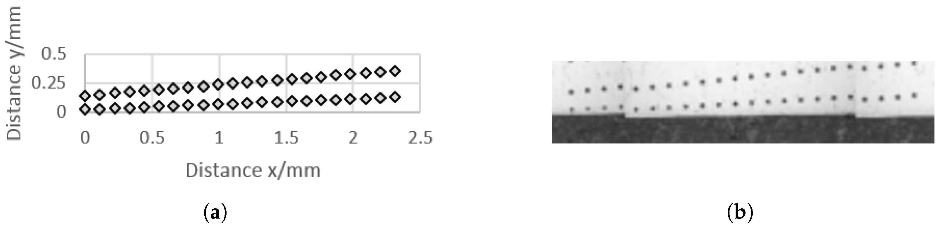
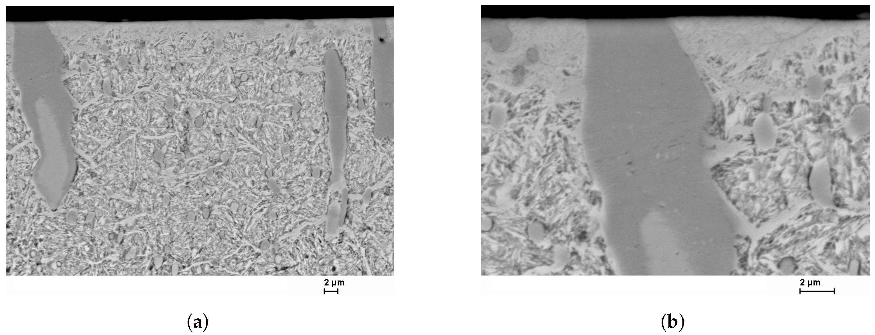
27]. The SEM images in
Figure 8 confirm and illustrate the heterogeneous behavior of the diffusion of nitrogen in a high-alloy tool steel. The layer near the surface is the compound layer (CL); the needled structure of the martensite and the nitrides are visible below. It is noticeable that the layer thickness of the CL is not homogeneous. The carbide interrupts the CL at the surface. Inside the carbide, the dark discoloration (according to [
28] MN) is noticeable, which almost surrounds the carbide in the interior. Some carbides are also completely converted to MN.
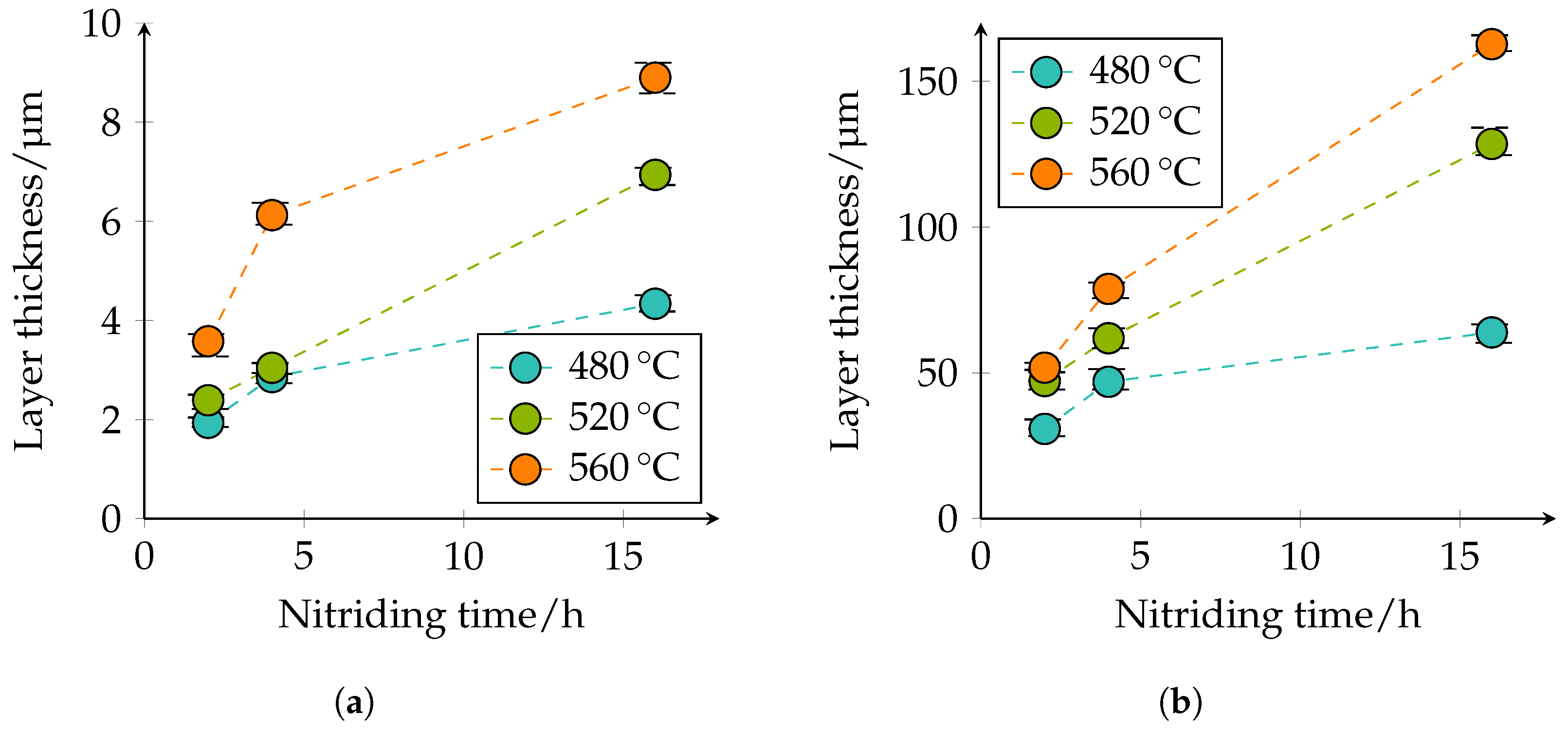
The thickness of the CL and DL, as well as the depth of transformation of carbides into nitrides were quantitatively determined in the optical microscopy images. The quantitative microscopic analysis confirmed the qualitative statements that with increasing temperature and duration, the layer thicknesses of the CL and DL increase; compare
Figure 9.
Figure 9a shows that the CL thickness at 480 °C and 2 h nitriding time is approximately 1.9 μm, at a nitriding time of 4 h approximately 2.9 μm, and at a nitriding time of 16 h approximately 4.3 μm. At 520 °C and 2 h nitriding time, the CL thickness is approximately 2.4 μm, at a nitriding time of 4 h approximately 3 μm, and at a nitriding time of 16 h approximately 6.9 μm. With a further increase of the plasma nitriding temperature to 560 °C and a nitriding duration of 2 h, the CL thicknesses of approximately 3.6 μm, at a nitriding time of 4 h approximately 6.1 μm, and with a nitriding duration of 16 h of approximately 8.9 μm; are achieved. A similar behavior can also be seen for the DL in
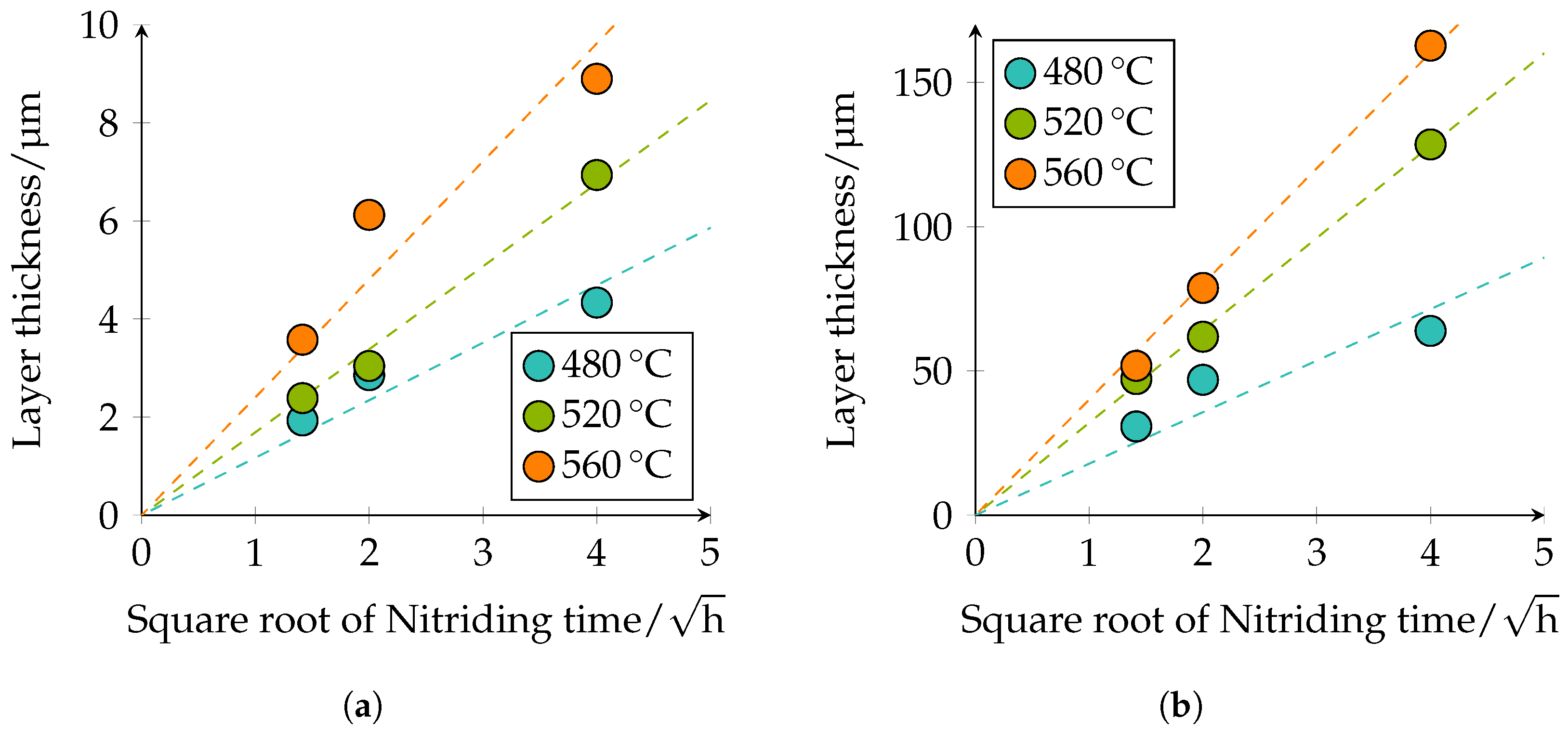
Figure 9b. At 480 °C and 2 h nitriding time, the layer thickness is approximately 31 μm, at 4 h approximately 47 μm, and at 16 h approximately 64 μm. At a plasma nitriding treatment of 520 °C and 2 h nitriding time, a layer thickness of approximately 47 μm, at 4 h approximately 62 μm, and at 16 h approximately 129 μm was observed. At 560 °C, the layer thicknesses increase further. Thus, a nitriding time of 2 h approximately 52 μm, at 4 h approximately 79 μm, and at 16 h approximately 163 μm DL thickness is present. The specified values of the different thicknesses of the compound and diffusion layers are additionally given in
Table 5. The observed behavior corresponds to the square root of the time law; see
Figure 10.
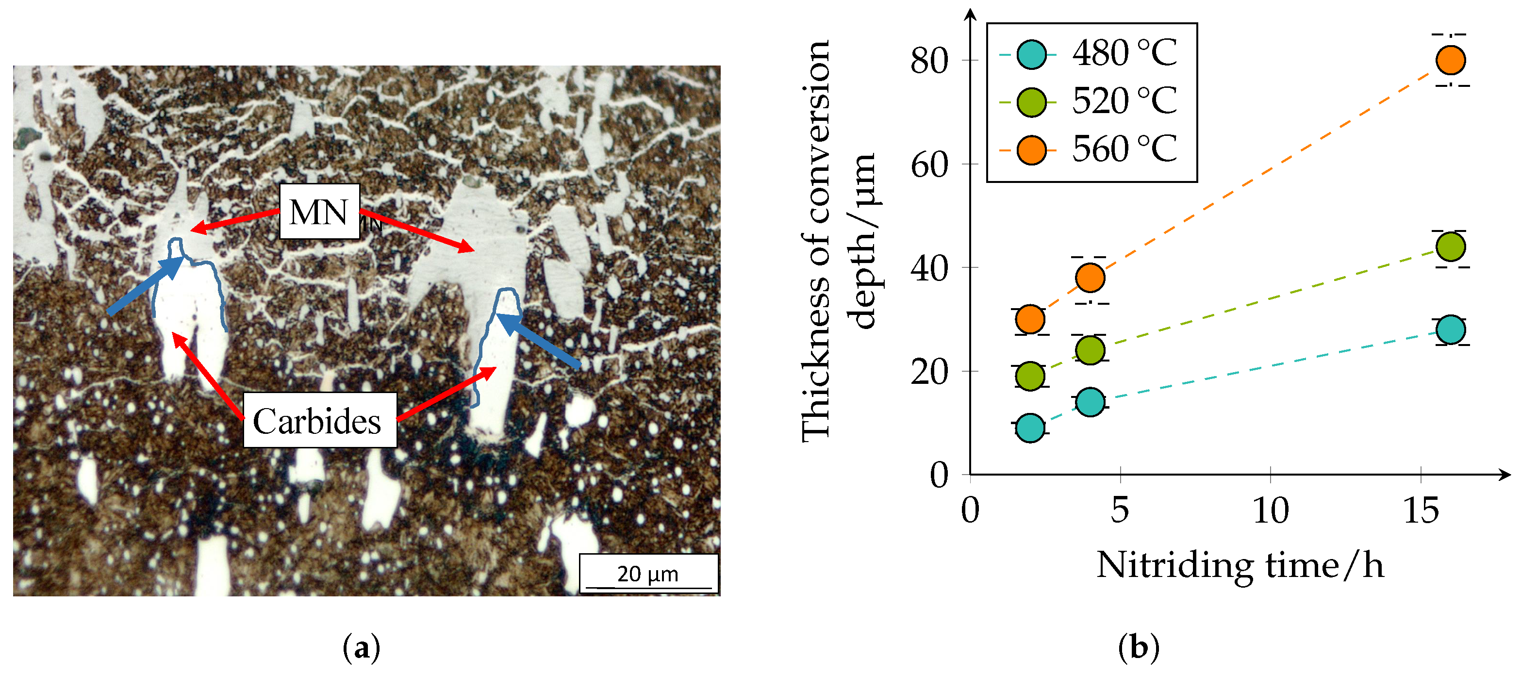
The conversion depth of the carbides/nitrides is shown in
Figure 11 and presents the same tendencies. It can be seen that the transformation of the carbides is not homogeneous; see
Figure 11a. Inside the carbides, nitrogen diffusion seems to be slower, but at the edges of the carbides or at the interface between carbide and matrix, they seem to transform faster. This was also observed in [
28].
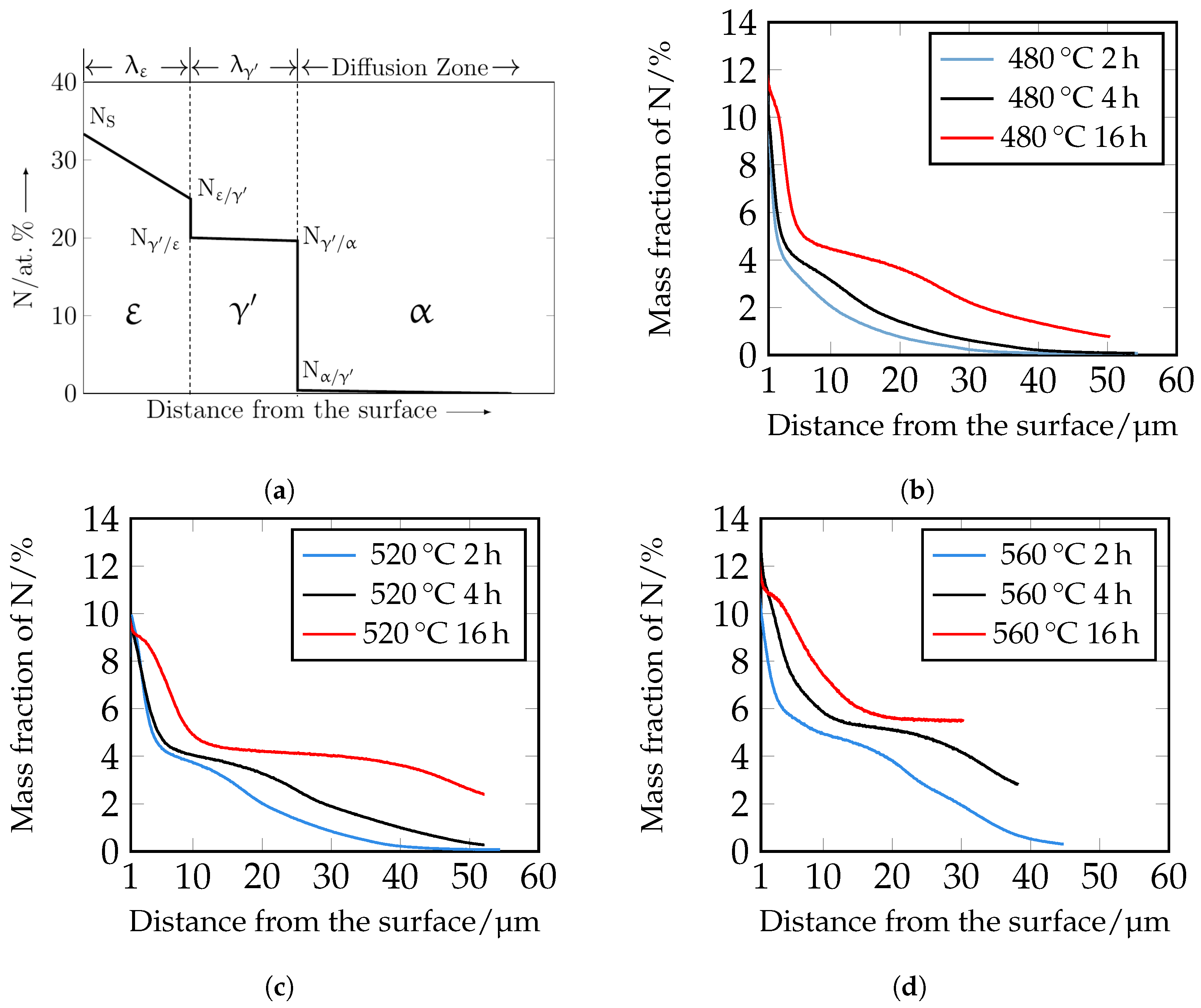
The nitrogen courses determined by means of GDOES are shown in
Figure 12. For a better understanding, the assignment of the individual phases
,
, and
is also shown schematically. It should be noted that the GDOES measurement is macroscopic, and therefore, the heterogeneous nitrogen concentration profile, which is partly present due to the carbides, is averaged in the results. The nitrogen curves show that with increasing time and temperature, the nitrogen content increases as a function of depth. The experimental nitrogen courses determined by GDOES serve as a comparison of the numerically calculated nitrogen concentration profiles.
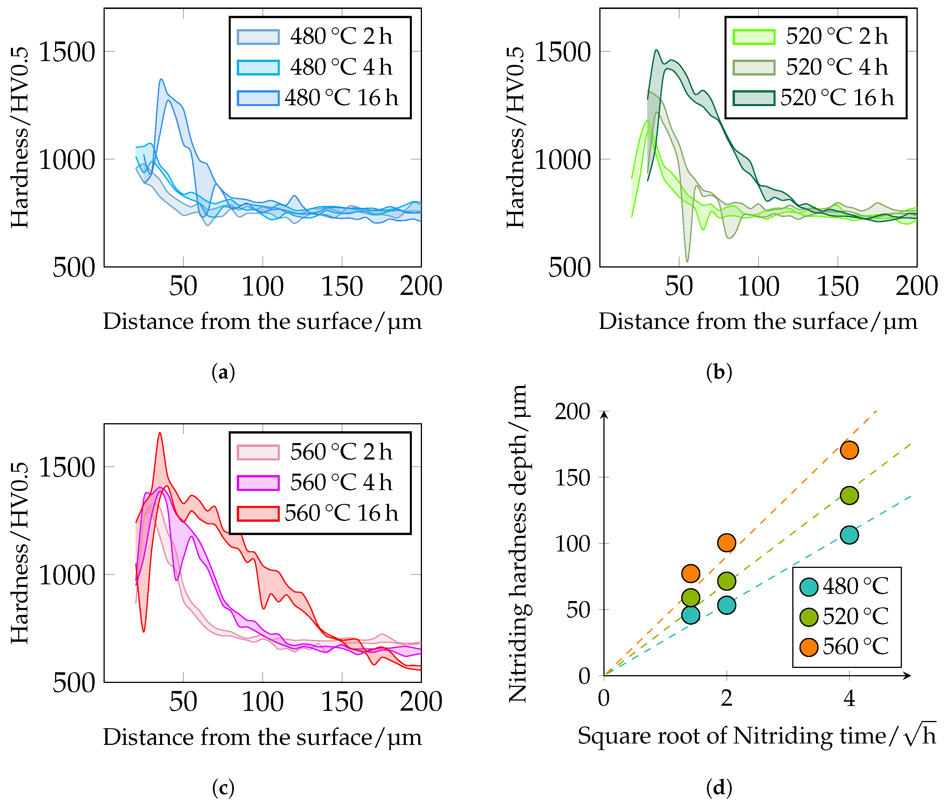
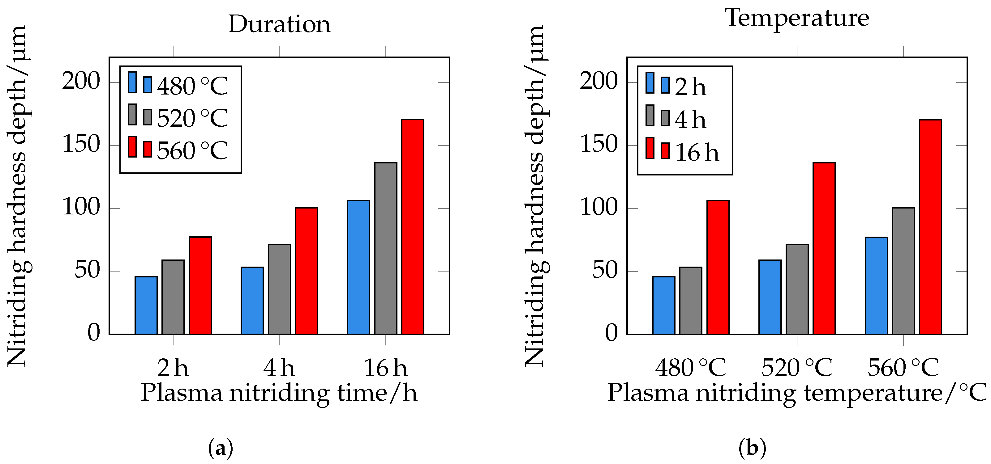
The different hardness profiles and nitriding depths (NHDs) are shown in
Figure 13. It can be seen that hardness and nitriding depth increase with increasing plasma nitriding temperature and duration. This correlates very well with the metallographically determined layer thicknesses of the DL. With increasing nitriding time at constant temperature, the maximum hardness increases. It should be noted that the first indentations in the near-edge area are too close to the surface when measuring hardness with
; see
Section 2.5. The observed drop in the near-edge area may be due to this circumstance. Further analyses using microhardness and nanoindentation are required in further work. The maximum hardness of the hardness curves is approximately 980
at 480 °C and 2 h and increases to 1360
at 480 °C and 16 h. At 520 °C, a maximum hardness of approximately 1180
can be observed at 2 h and at 16 h a maximum hardness of 1500
. At 560 °C and 2 h nitriding time, a maximum hardness of approximately 1325
and at 16 h of approximately 1660
is present. The hardness of 1660
seems a bit too high. Possibly, large primary carbides were hit during the measurement, which influenced the result. Further maximum hardnesses are 1400
–1450
. The NHD was defined as the vertical distance from the surface to the point where the hardness corresponds to the core hardness +50
(limit hardness). As expected, the nitriding depth also correlates with the root-time law. The nitriding depth at 480 °C and 2 h is approximately 45 μm, at 4 h approximately 55 μm, and at 16 h approximately 105 μm. At 520 °C and 2 h, it is approximately 60 μm, at 4 h approximately 70 μm, and at 16 h approximately 135 μm. At a temperature of 560 °C and a treatment time of 2 h, the nitriding hardness depth is approximately 75 μm, at 4 h 100 μm, and at 16 h 170 μm. The NHD is shown in
Figure 13d and
Figure 14. Please note that the core hardness varies due to the tempering effects during plasma nitriding; see
Table 6.
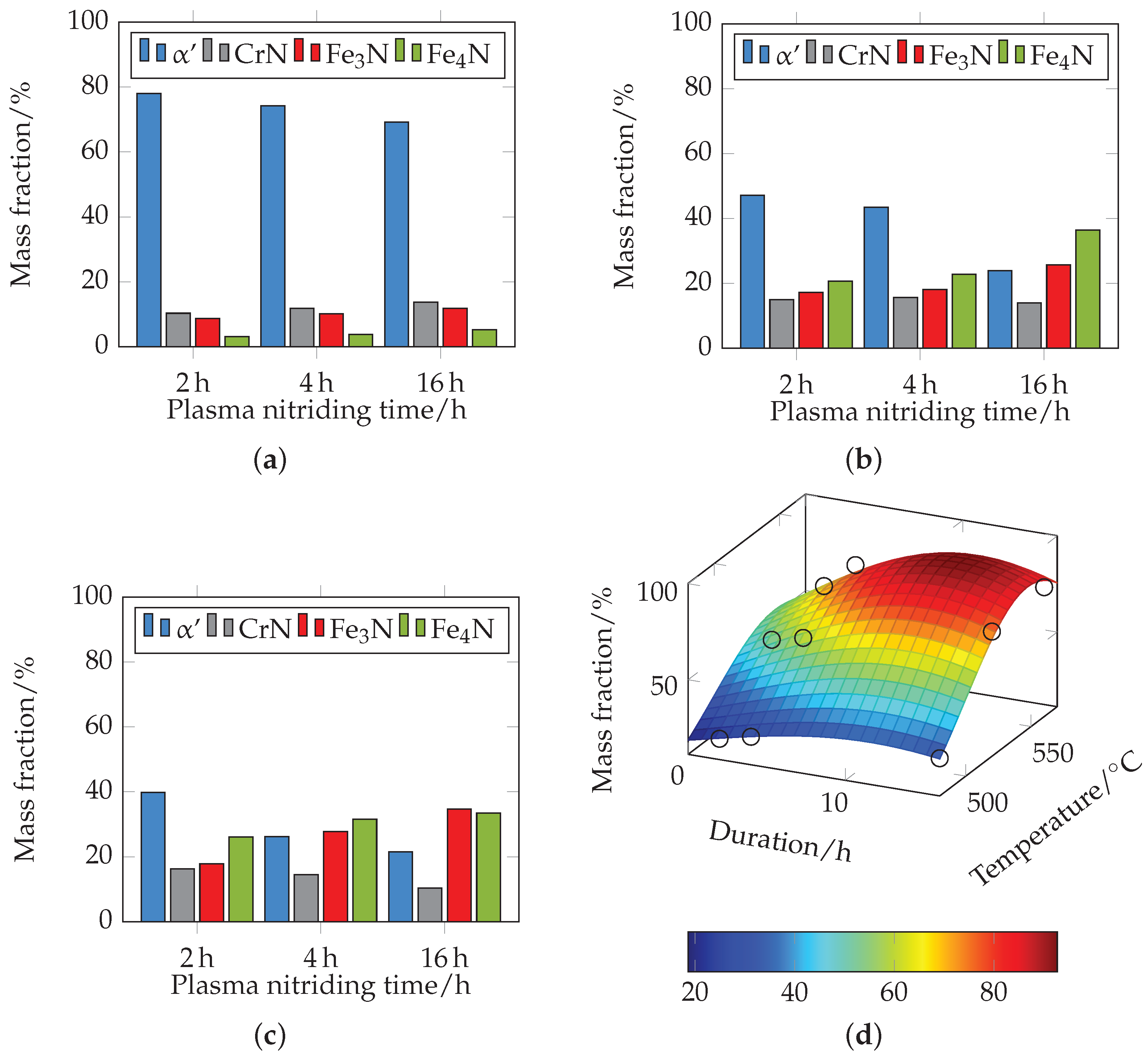
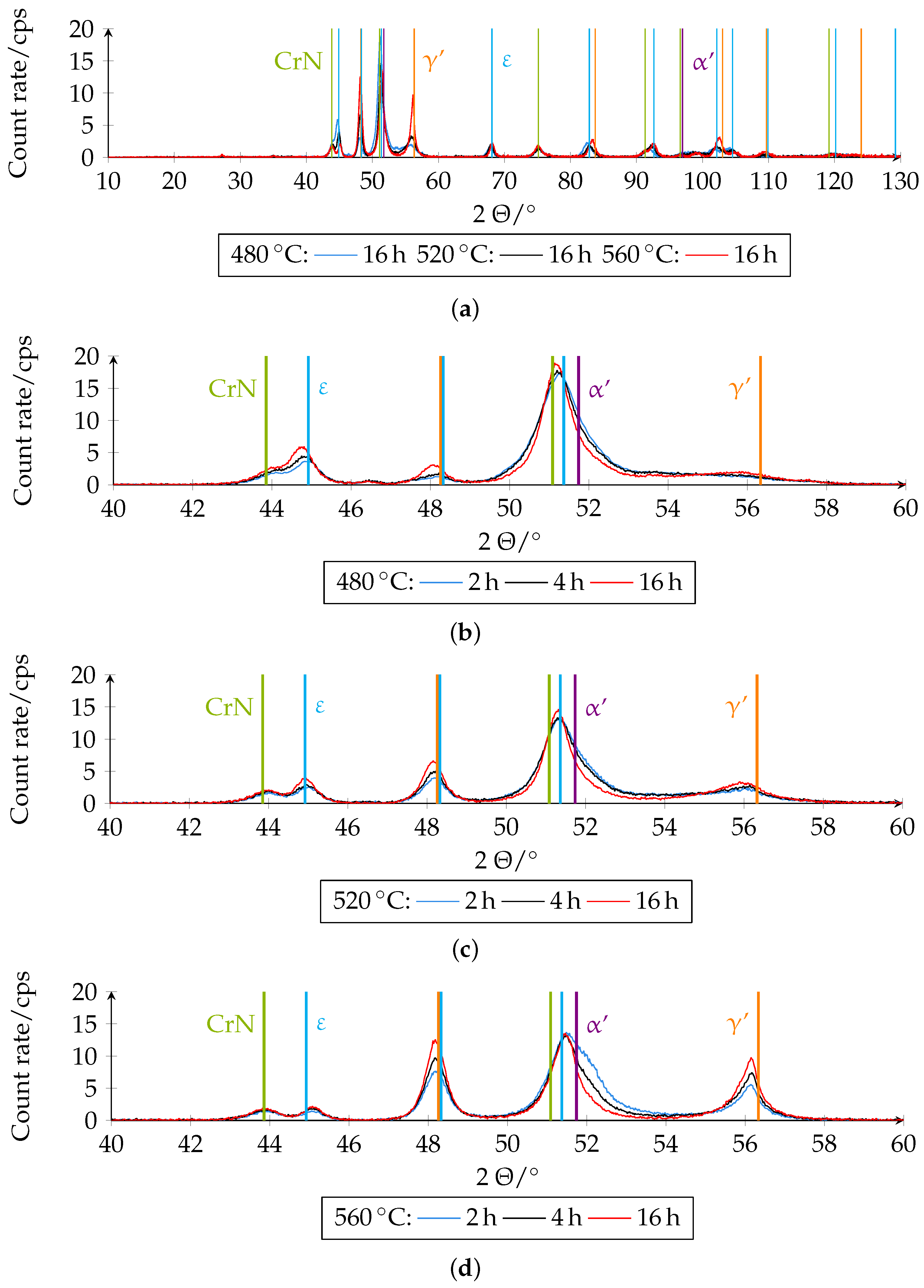
Figure 15 shows the different XRD diffractograms on which the quantitative analysis was based. The phase fractions of the boundary layer of the differently plasma-nitrided samples determined quantitatively by XRD can be seen in
Figure 16.
Figure 16a shows the mass contents for different plasma nitriding durations at 480 °C. The mass fractions of ferrite (α)/martensite (
) decrease with increasing duration from approximately 78% at 2 h to approximately 69% at 16 h, and the fractions of
,
and CrN increase slightly. At 520 °C (see
Figure 16b), a further significant decrease in the mass content of ferrite (α)/martensite (
) from 47% at 2 h to 24% at 16 h can be seen compared to 480 °C. The proportions of
and
increase accordingly, with the proportion of
predominating. The proportions of CrN remain almost constant. At 560 °C (see
Figure 16c), a further decrease in the mass content of ferrite (α)/martensite (
) from 40% at 2 h to 21.5% at 16 h can be observed. Here, too, the proportions of
and
increase accordingly. The proportion of
increases from 18% at 2 h nitriding time to 35% at 16 h nitriding time and the proportion of
from 26% at 2 h nitriding time to 33.5% at 16 h nitriding time. The proportions of CrN decrease slightly with increasing duration. At 560 °C, there is a higher mass fraction of
than at the other temperatures investigated.
Figure 16d shows the approximated 3D plot of the sum of the mass fractions of
,
and CrN. Since the mass fraction of
with
,
, and
, the fraction of ferrite (α)/martensite (
) can be interpreted inversely to the plotted curve. It can be clearly seen that the proportion of nitride phases increases with increasing temperature and nitriding time, and the proportion of ferrite (α)/martensite (
) decreases accordingly. This correlates with the previous results. The XRD measurements record a certain measurement volume. With increasing nitriding temperature and duration, the compound layer thickness increases so that the proportions of the initial microstructure decrease. It should be noted that the changed composition can thus possibly be attributed to a higher layer thickness. The local mass fractions of the compound layer therefore do not necessarily have to be changed.
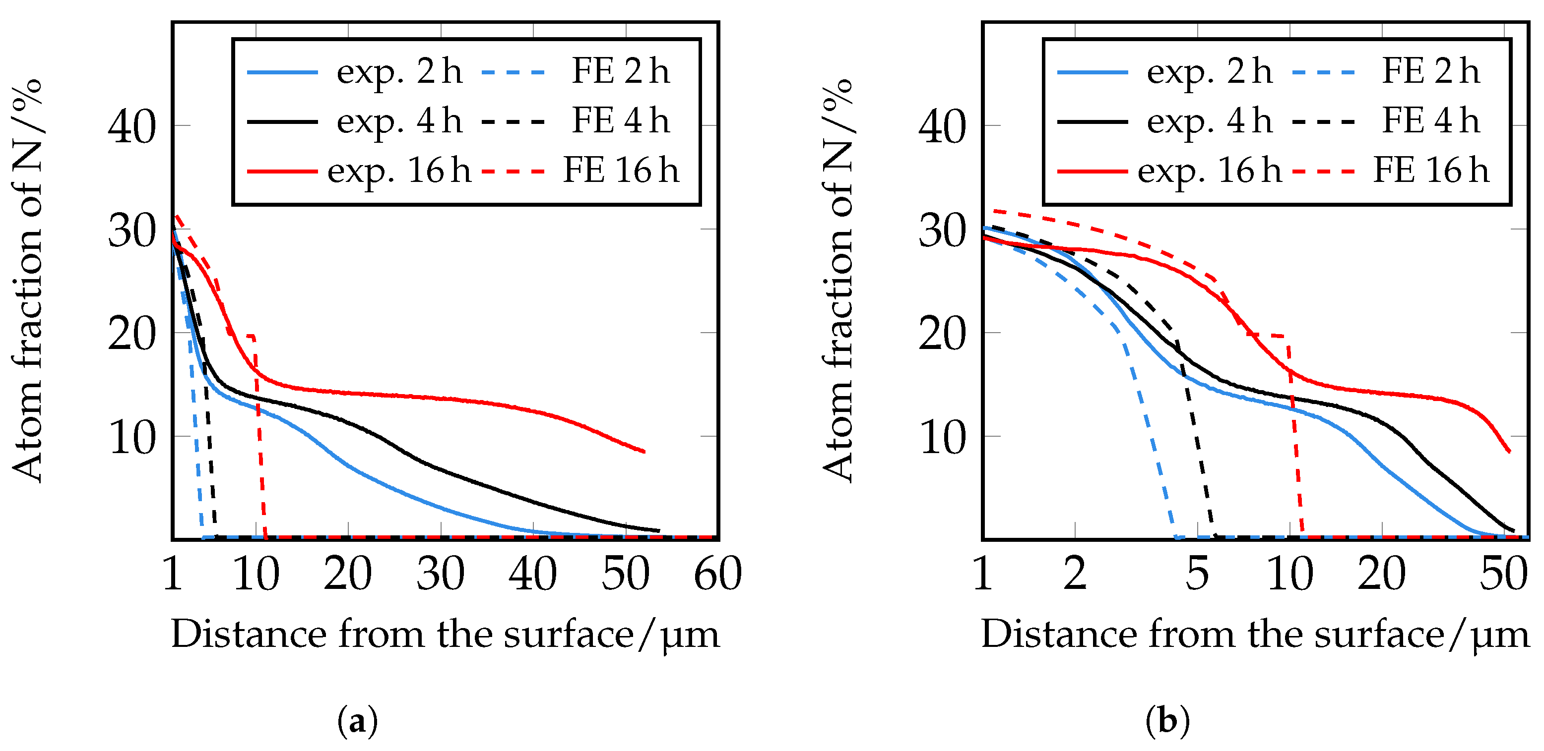
In the following paragraph, the results of the FE simulations are presented and compared with the experimental results. More detailed work on the microstructure simulations will be published in further studies. The diffusion coefficients were calculated as described in
Section 2.7. They were at first calculated according to [
33,
34] and iteratively adjusted in a further step. The results of the FE simulations of the nitrogen distribution after plasma nitriding at 520 °C for 2 h, 4 h, and 16 h with varied diffusion coefficients D
N, D
N, D
N, D
NCarbide, and D
NNitride and the comparison with the experimentally determined nitrogen concentration profiles are shown in
Figure 17,
Figure 18 and
Figure 19.
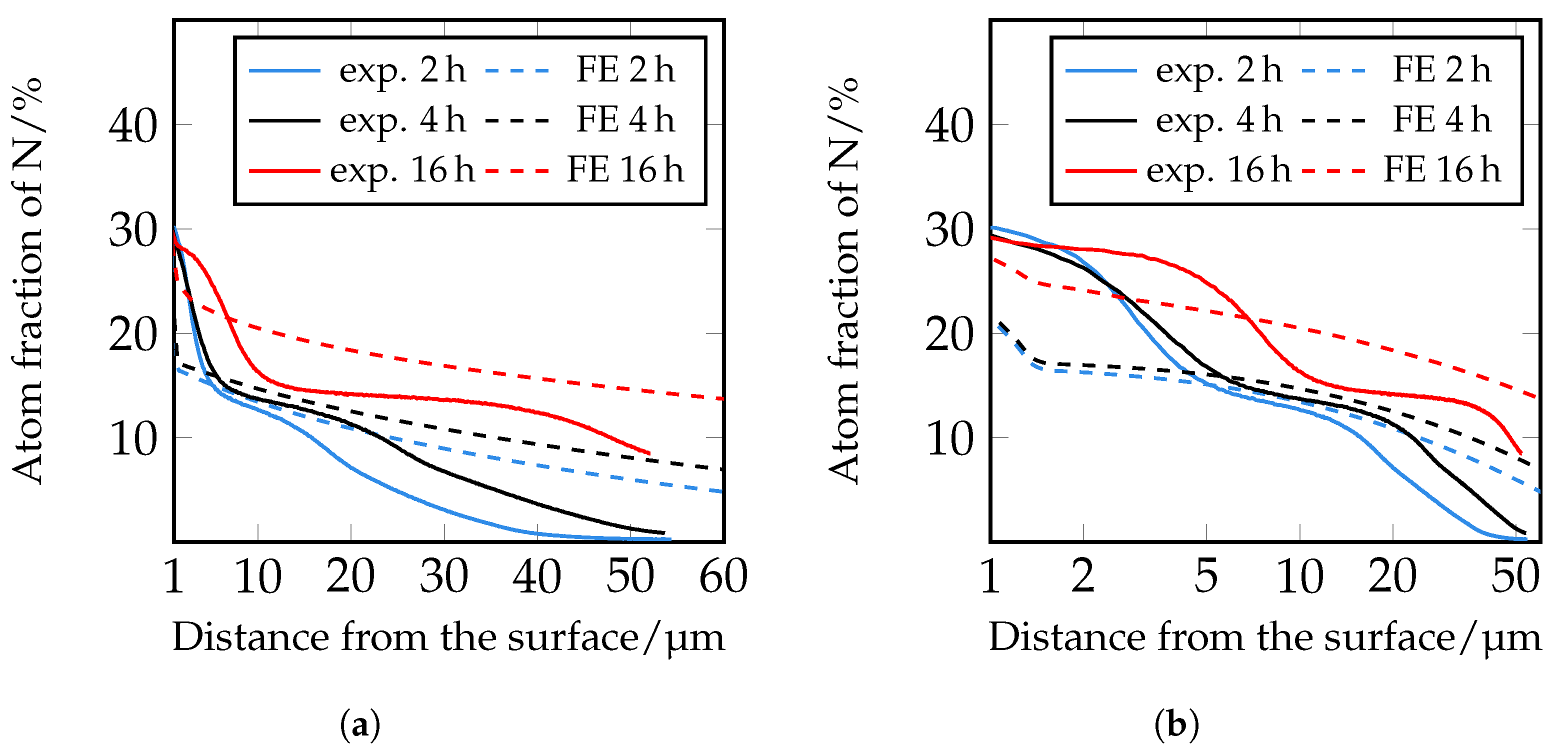
The simulation of the nitrogen depth profiles with the different diffusion coefficients according to [
33,
34] show deviations from the experimentally determined nitrogen depth profiles. The calculated nitrogen course based on the diffusion coefficients according to [
33] shows a good agreement in the near-surface range of the nitrogen courses up to approximately 5 μm. In the further calculated course, the decrease of the nitrogen content is too steep, so that there is no good correlation with the experimentally determined values. The diffusion coefficients according to [
34] show greater deviations in the course in the front area of the nitrogen concentration profiles than the nitrogen courses determined with the coefficients according to [
33]. In deeper areas, on the other hand, there is better agreement. It should be noted that the diffusion coefficients used were determined for pure iron. Further reasons for the deviation are to be seen in the fact that according to [
39], diffusion coefficients for
and
nitrides, which are determined during plasma nitriding, are problematic, since during plasma nitriding, as the nitrogen diffuses, inwards a part of the surface is sputtered away at the same time. Furthermore, according to [
39], it should be noted that when applying a certain diffusion coefficient, the corresponding model used to evaluate the diffusion coefficient should be taken into account.
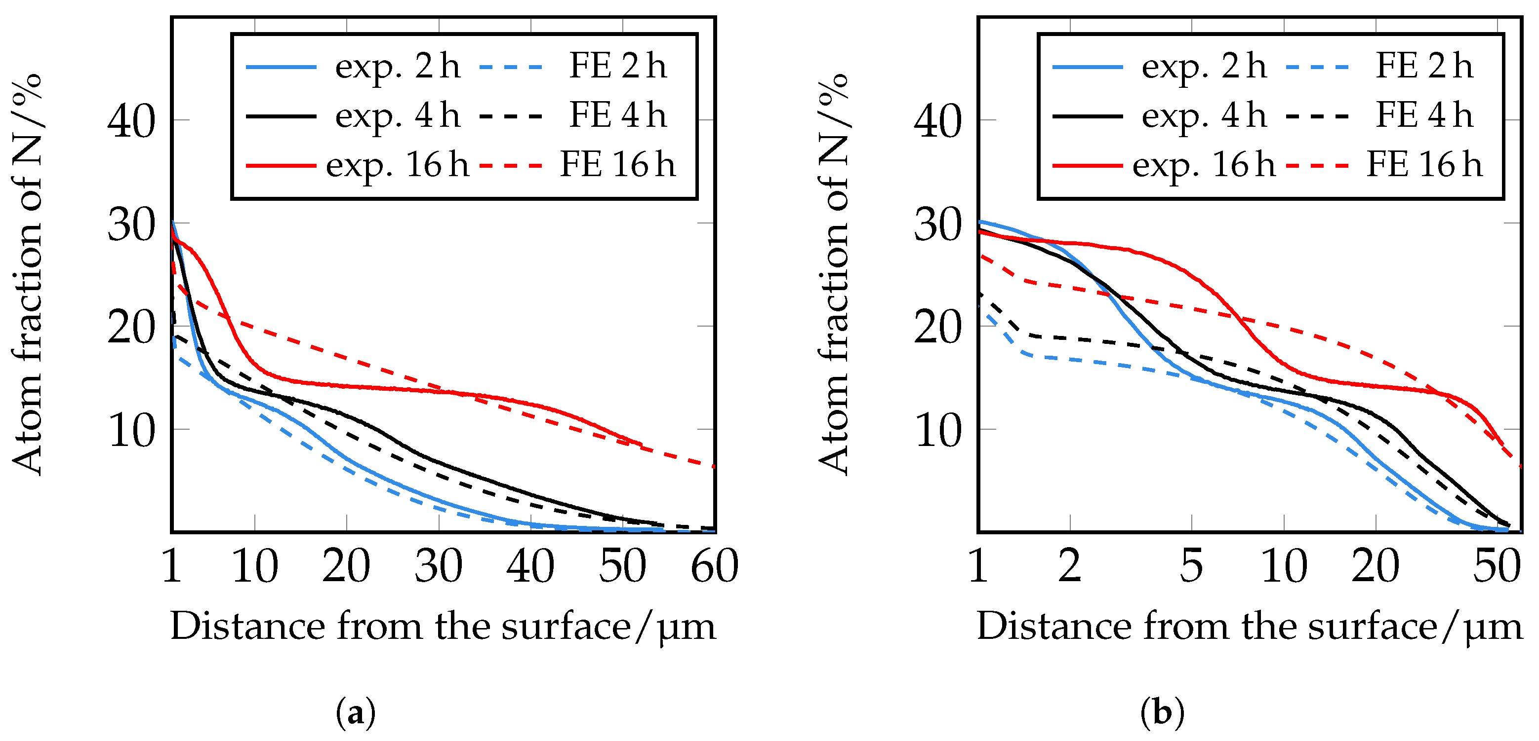
Therefore, in a following step, an iterative adjustment of the diffusion coefficients was carried out; see
Figure 19. Here, too, there are still deviations in the area close to the surface, but from approximately 5 μm onwards, the closest agreement between the experimentally determined and numerically simulated concentration profiles of all diffusion coefficients used so far can be seen. However, it is clear that a further adjustment of the diffusion coefficients and also of the solubility limits seems to be necessary. Since the closest agreement is found for the iteratively adjusted diffusion coefficients, which are listed in
Table 7, this model was further used to show the influence of the carbides.
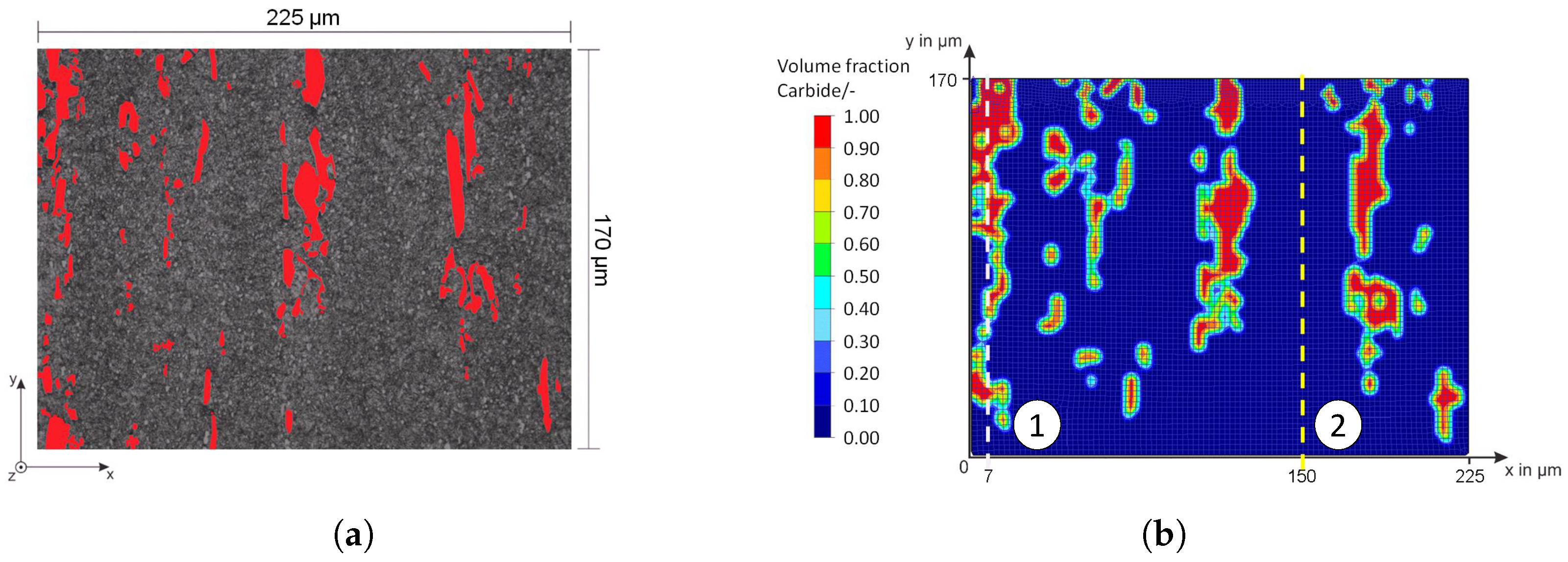
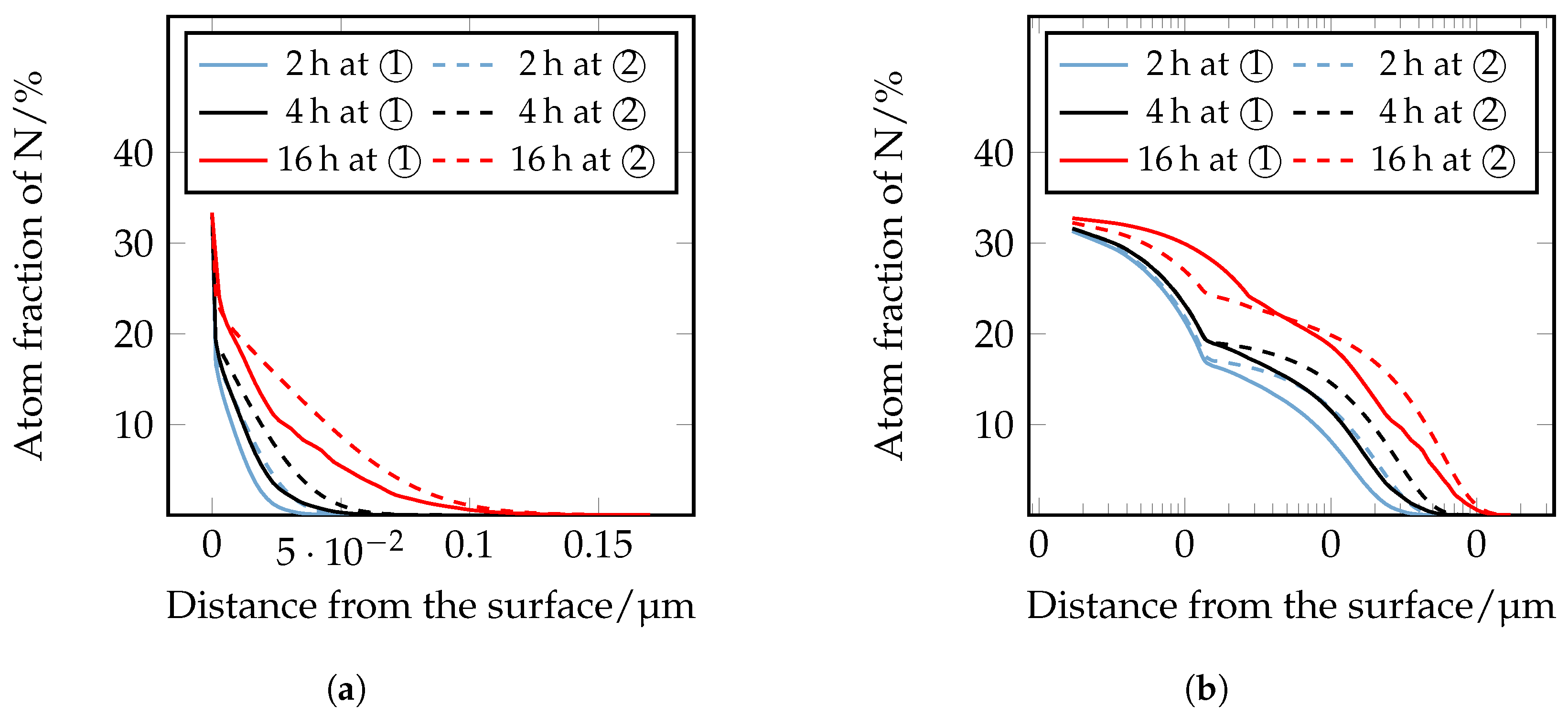
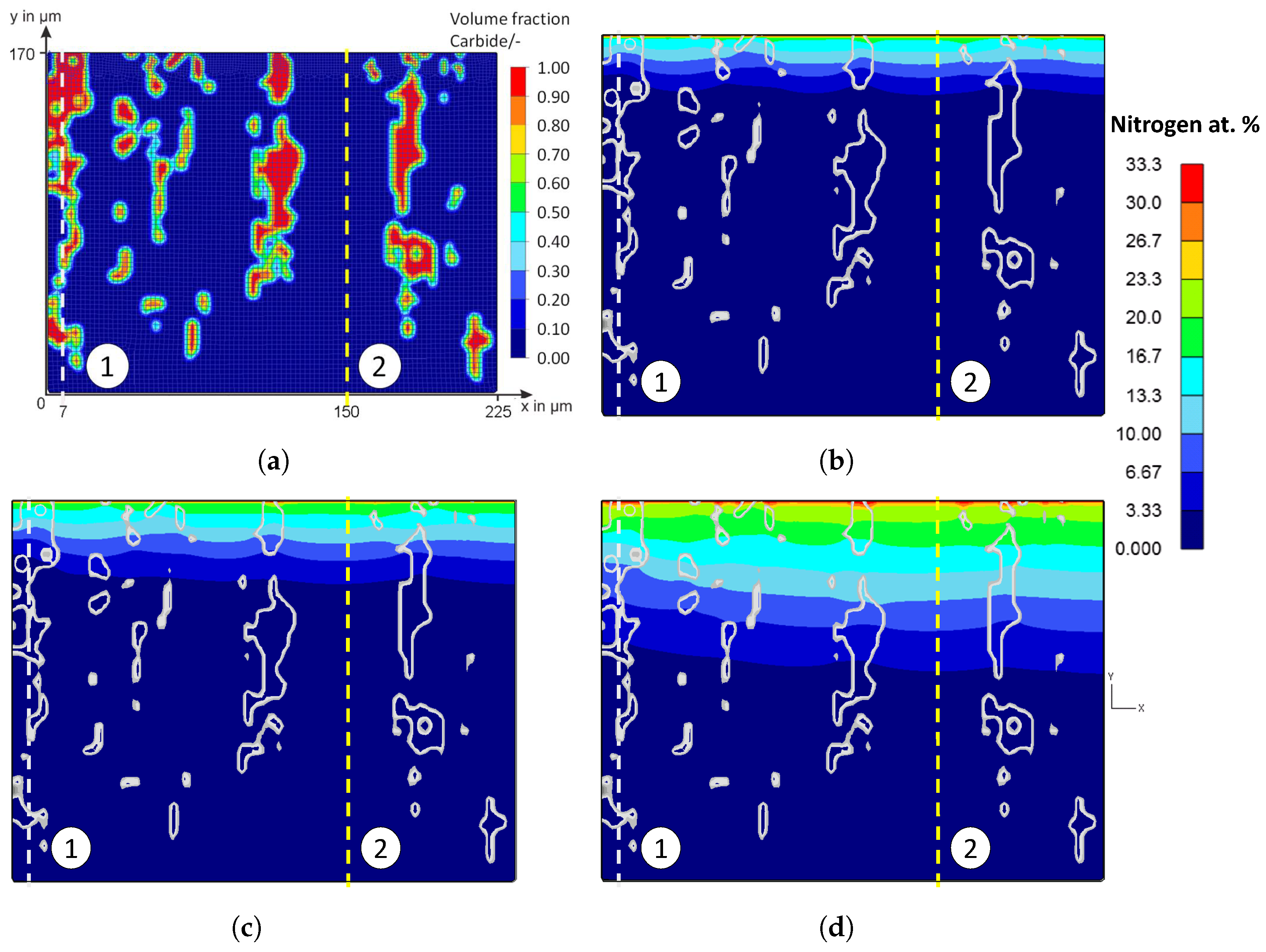
Figure 20 shows the false color images of the nitrogen concentration profile of the microstructure of the iteratively adjusted different diffusion coefficients and in consideration of
and
, which are listed in
Table 7. In addition, a comparison of the calculated nitrogen concentration profiles in carbide-rich (7 μm) and carbide-poor (150 μm) areas after different plasma nitriding durations is shown in
Figure 21.
Based on the FE simulations, the following trends can be derived:
In carbide-rich areas (here in the example at 7 μm), carbides (M
7C
3) and nitrides (MNs) influence the nitrogen diffusion. There, the nitrogen-poorer areas are clearly visible at the position of the carbides/nitrides. It can be seen that the lower diffusion coefficient noticeably inhibits nitrogen diffusion. In the area of the carbides/nitrides, nitrogen diffusion is inhibited both within the carbides/nitrides and in the peripheral areas of the carbides/nitrides. Therefore, the local diffusion coefficient in the carbides and nitrides can affect the nitrogen diffusion of a high-alloy tool steel, thus affecting the thickness of the diffusion layer and, theoretically, other local properties such as hardness. In the carbide-poor areas (here in the example at 150 μm), the nitrogen can penetrate deeper. Note, however, that grain boundary diffusion was not taken into account in the simulation. This illustrates the influence of the carbides and shows the possibilities of the new approach for considering the microstructure in the numerical calculation of diffusion processes using the FEM; compare
Figure 2 and
Figure 7 to
Figure 8. By implementing further material data in the material models, it will be possible in future work to have a more realistic account of the different volume changes in the respective microstructural components/phases and the residual stresses that occur, for instance, by taking them into account. In the context of this work, the possibilities of the FE method were first presented, taking into account the carbides of the high-alloy tool steels. The further experimental validation will take place in future work.


 ,
, 


