Article

Fatigue Bending of V-Notched Cold-Sprayed FeCoCrNiMn Coatings

1
Department of Innovation Engineering, University of Salento, Via per Arnesano, 73100 Lecce, Italy
2
Thermal Spray Center CPT, Universitat de Barcelona, 08007 Barcelona, Spain
3
Faculty of Mechanical Engineering and Ship Technology, Gdansk University of Technology, Narutowicza 11/12, 80-233 Gdansk, Poland
*
Author to whom correspondence should be addressed.
Metals 2022, 12(5), 780; https://doi.org/10.3390/met12050780
Submission received: 30 March 2022 / Revised: 26 April 2022 / Accepted: 29 April 2022 / Published: 30 April 2022
(This article belongs to the Section Entropic Alloys and Meta-Metals)

Abstract

:
Cold-spray coatings were produced by FeCoCrNiMn high-entropy alloy powders deposited on carbon steel substrate. The coatings were realized at intermediate temperature and high pressure (at 1100 °C and 7 MPa). The coating microstructure was characterized by scanning electron microscopy and X-ray diffraction, revealing a very dense deposition and high flattening ratio of the splatted particles. This had a large influence on the strong adhesion of the coating to the substrate. The hardness and residual stress profiles were measured through nanoindentation and X-ray diffraction from the peak broadening measured layer by layer. The cyclic behavior of the coatings was evaluated through three-point bending tests performed on V-notched samples coated via cold spray. Cyclic tests were performed at different maximum strokes from 0.3 to 3.6 mm in order to monitor the crack initiation and propagation during bending tests. The fracture surface aspect was analyzed by scanning electron microscopy in order to reveal the fracture mechanisms in different deformation conditions.

1. Introduction

High-entropy alloys (HEAs) exhibit new and interesting properties thanks to their particular crystal configuration due to the severe lattice distortion deriving from the well-known called cocktail effect [1,2,3]. High-entropy alloys are composed be a minimum of five metals in equiatomic or non-equiatomic configurations. The high entropy of the crystal configuration leads to exceptional mechanical properties in a very broad range of in-service temperatures [4,5]. Obviously, the main properties depend on the crystal structure belonging to the single metal combination (FCC, BCC, FCC + BCC) [6]. It has been largely demonstrated that powder metallurgy processing routes can allow for a further increase in the mechanical properties of high-entropy alloys [7,8]. This is mainly due to the crystal modification at the nanoscale. Some scientific evidence has demonstrated how cold-spray coatings of high-entropy alloys powders show sound and high-strength protective layers [9]. HEAs appear as an optimal solution for corrosion protection; many data belonging to various alloy configurations were described in [10]. Obviously, the corrosion resistance of these alloys strongly depends on the alloy configuration, on the crystal structure belonging to the alloy composition, and on the processing route. Cold spray is well known for providing coatings for surface protection and/or repair. As a matter of fact, it has been demonstrated how compositionally complex alloys allow for an improvement in corrosion resistance [11]. It was also specified how the complexity of the alloy configuration is directly related to the increase in mechanical and physicochemical properties [12,13,14]. The uniqueness of this technology is represented by the aspect that the coating formation acts at temperatures lower than the melting temperatures of the impacting particles, leading to very severe plastic deformation upon impact with consequent microstructural features, leading to high adhesion of the coatings to the substrate and high strength of the coatings [15,16,17]. Upon impact under severe conditions, particles exhibit the well-known and debated phenomenon of adiabatic shear instability leading to local nanostructuring of the particle microstructure [18,19,20]. Under the given processing conditions, this can induce high residual stresses and high adhesion strength of the coatings [21,22,23,24]. This can be very useful for the fatigue behavior of the produced coatings [25,26,27]. High-strength aluminum alloys deposited on softer substrates can improve the fatigue life of components [28]. Obviously, this can take place only if optimal processing conditions are employed during spraying [29]. Moreover, in the case of repaired structures, cold spraying can lead to an improvement of the fatigue life of the repaired components [30,31]. In this case, the effect depends on the processing parameters and on the coupling between the substrates and the employed particles [32,33]. As a matter of fact, excellent results have been obtained for steel repaired with nickel or nickel-based superalloys [34,35,36,37]. Very recently, interesting papers were presented on the possibility of employing high-entropy alloy powders for cold-spray coating production [38,39]. Authors evidenced that the microstructural evolution and the residual stress development are fundamental for the high mechanical properties in the coatings [40].
Many studies are available in the literature on the high strength and ductility properties of FeCoCrNiMn alloy (known as Cantor alloy), as well as on its excellent cryogenic properties, fracture toughness, and corrosion resistance [41,42,43]. For the application of coatings as protective layers under aggressive environments and mechanical loading, the fatigue behavior of the produced coatings must be precisely characterized. To the best of the authors’ knowledge, no data are available in the literature on the fatigue behavior of high-entropy alloys used as cold-spray coatings. The aim of the present paper was to describe the fracture behavior of FeCoCrNiMn high-entropy alloy cold-sprayed on V-notched steel substrates under cyclic three-point bending.

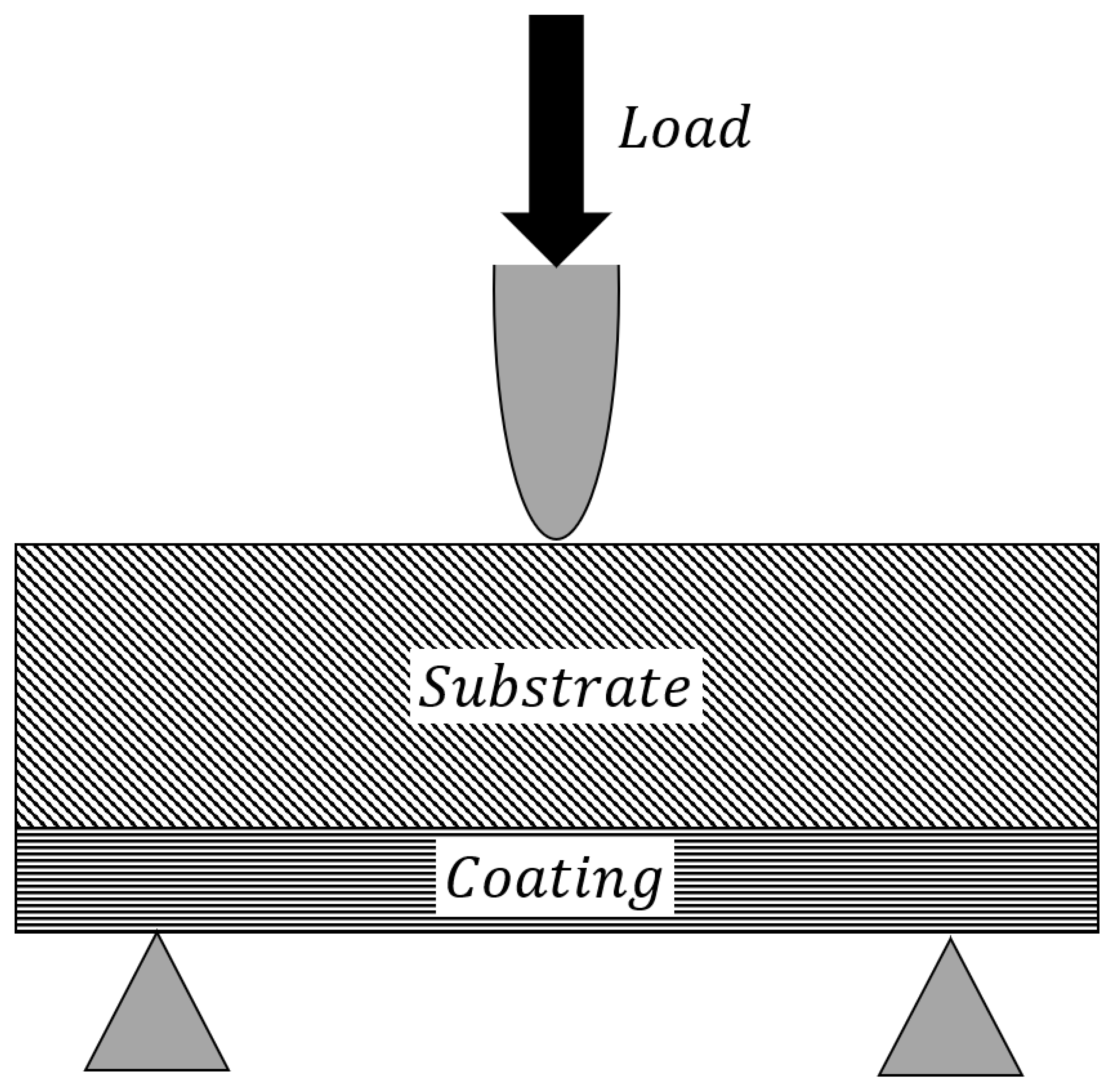
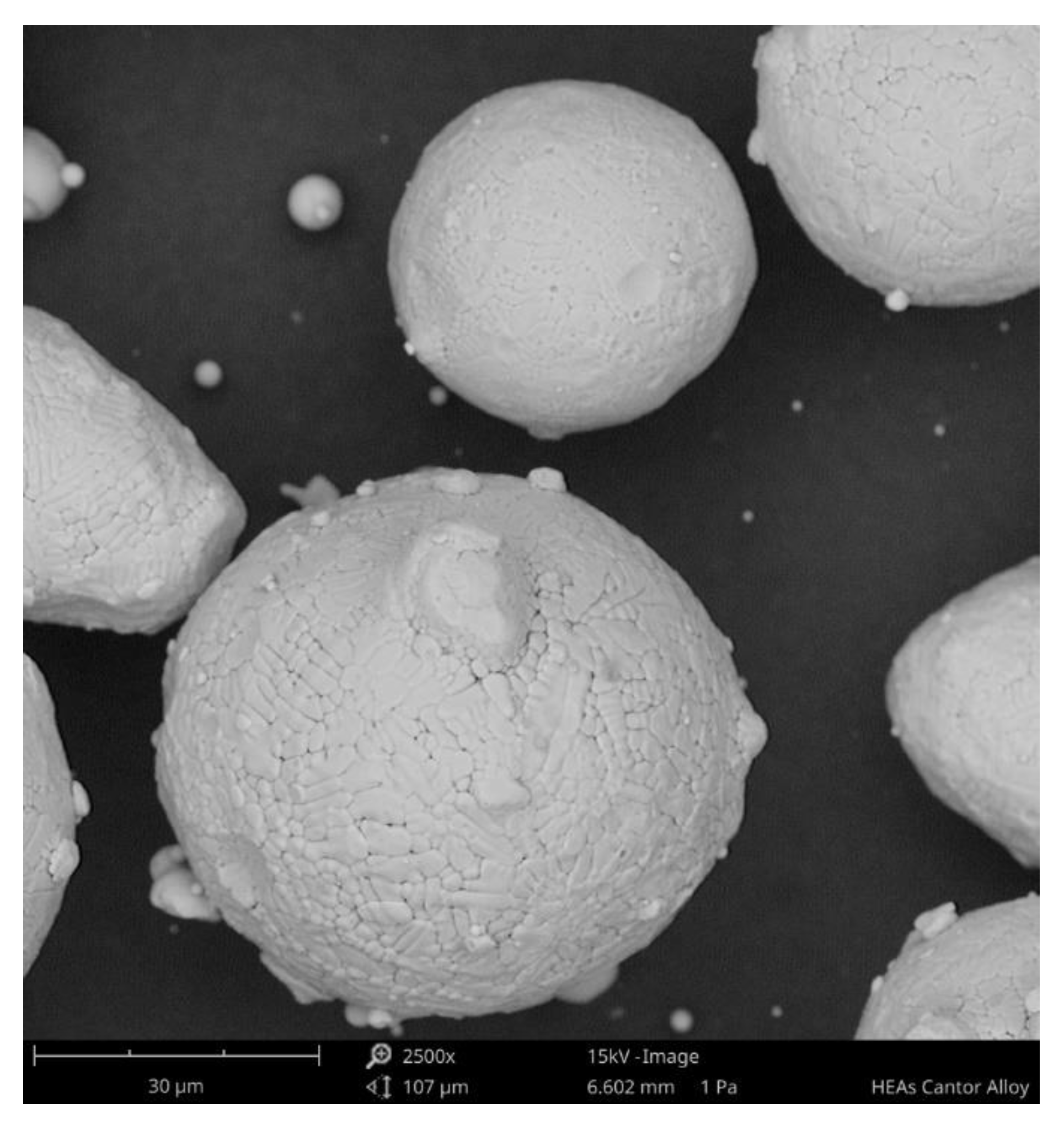
2. Materials and Methods

High-entropy alloy powders of FeCOCrNiMn (by Vilory Advanced Materials Technology Ltd., CN) were provided in equiatomic composition [9]. Particles were characterized before spraying through scanning electron microscopy with a ZEISS EVO40 microscope. Particles were cold-sprayed on V-notched carbon steel substrates (120 mm × 30 mm × 15 mm) with a PCS-100 high-pressure cold-spray machine (Plasma Giken Co., Ltd. Osato, Saitama, Japan). Prior to deposition, the surfaces of the carbon steel sheets were grit-blasted with alumina (F24) to roughness Ra ≈ 7 µm. The temperature and pressure employed during spraying were 1100 °C and 7 MPa, respectively. The stand-off distance was 15 mm, the power feed was 2 rpm, and the robot speed was 500 mm/s [9]. These processing parameters were employed because, in our previous work, they were identified as optimal for high-density and high-adhesion-strength coatings. Powders and coatings were characterized though X-ray diffraction (XRD) by employing a Malvern PANalytical X’Pert PRO MPD θ/θ Bragg–Brentano with X’Pert software (Malvern, UK) for phase analysis, with Cu Kα (λ = 1.5418 Å) radiation and a working power of 45 kV–40 mA. X-ray diffraction was also employed for the measurement of residual stresses in a direction parallel to the spray direction by removing thin layers through electropolishing before each measurement [44]. Metallographic preparation was carried out in accordance with the ASTM E1920-03 standard. The coating microstructure was observed by employing the Leica DMI 5000M optical microscope (OM). The Leica microscope image analyzer was used to calculate the coating thickness. The Shimadzu HMV (Tokyo, Japan) was used for 10 measures of microhardness on the Vickers scale for each coating, with a load of 0.1 kg of F (HV0.1). Cyclic three-point bending tests were performed on the cold-sprayed sheets by employing a Zwick/Roell standard testing machine. The test configuration is shown in Figure 1.
Cyclic bending tests were performed at different levels of maximum stroke from 0.3 to 3.6 mm. The test was stopped every 100 cycles, and the coating surface was observed in order to monitor the superficial fracture behavior. The fracture surface of the coatings after rupture was observed through scanning electron microscopy by employing a Zeiss EVO40 SEM equipped with EDS.

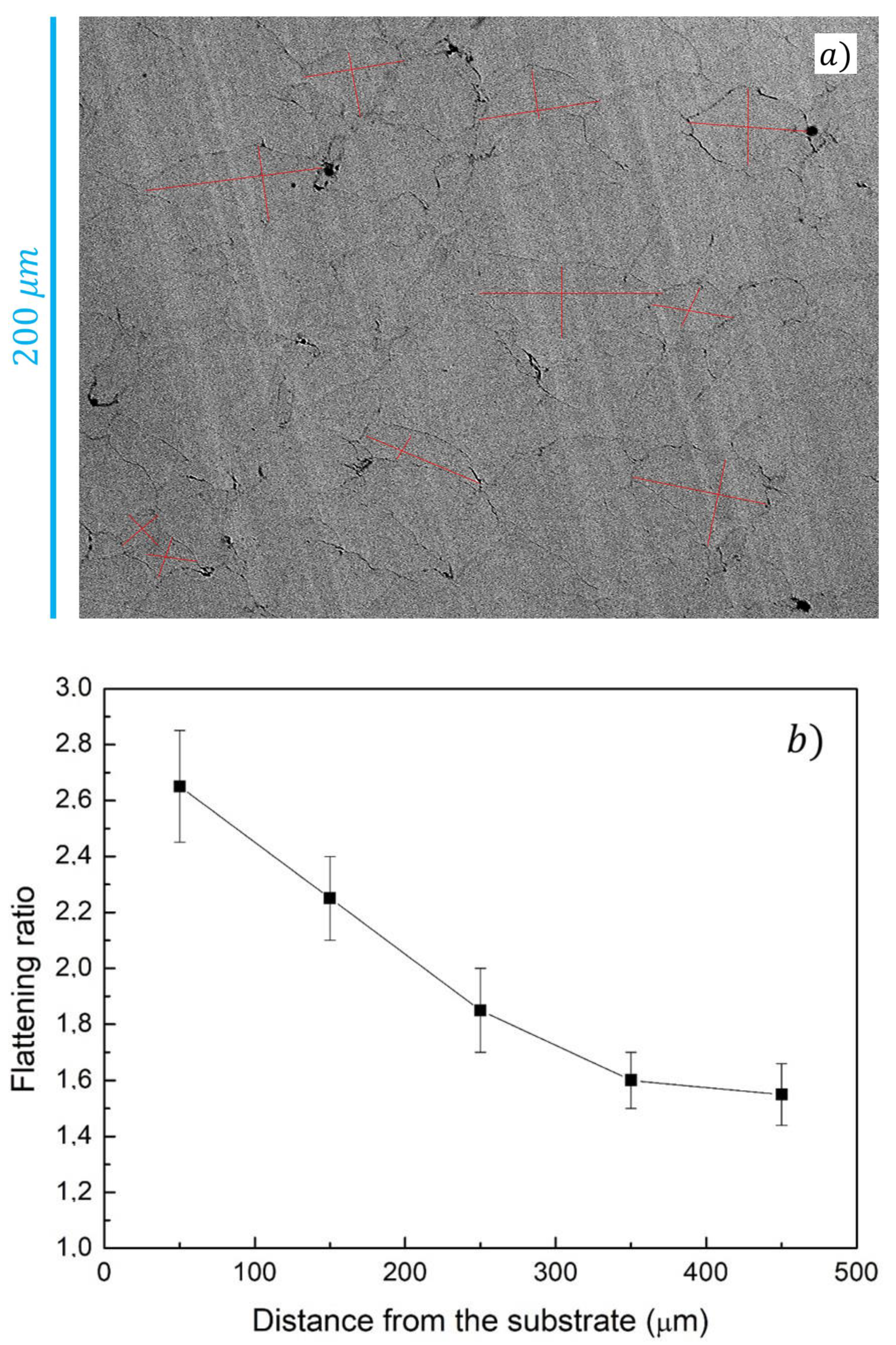
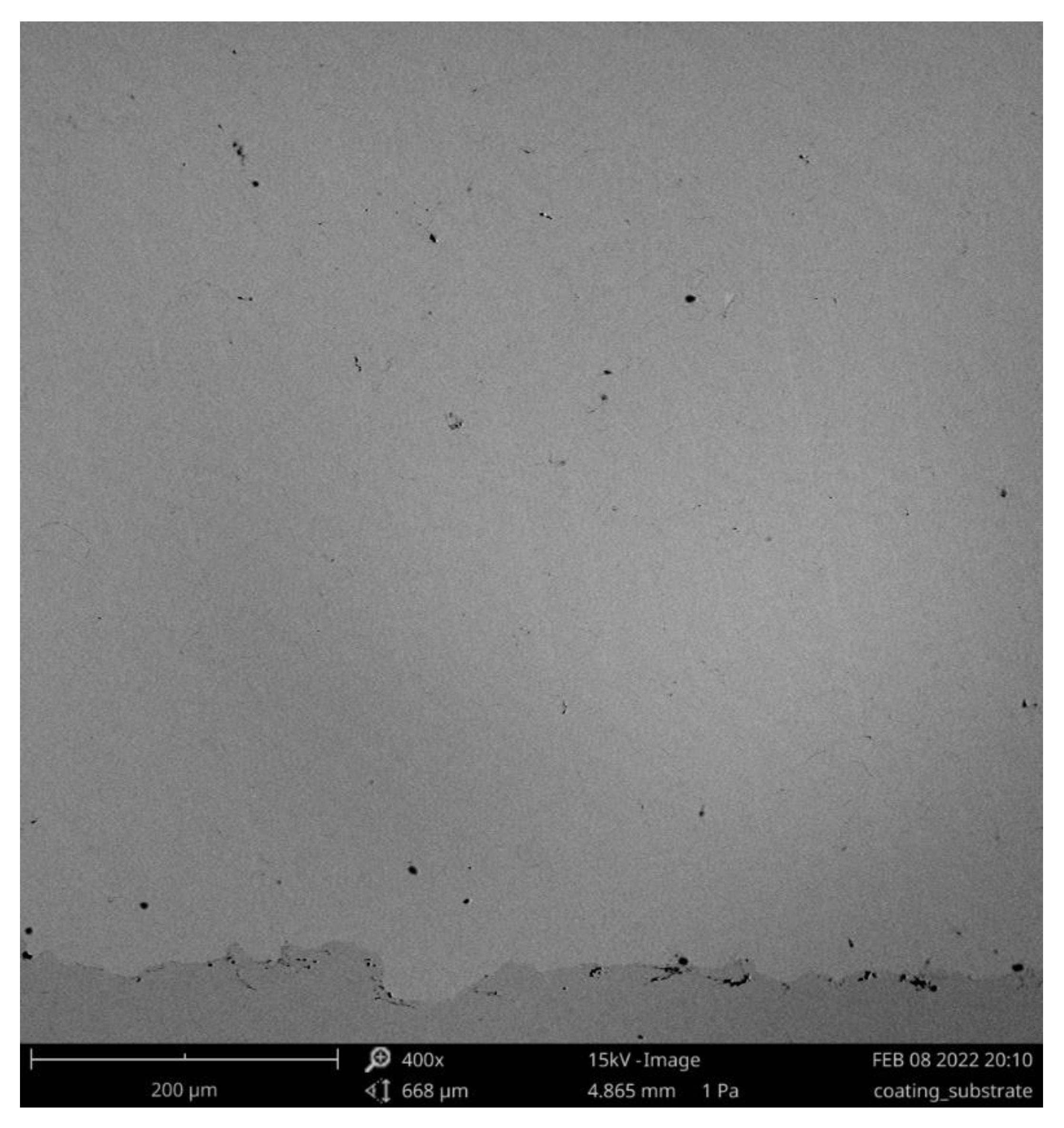
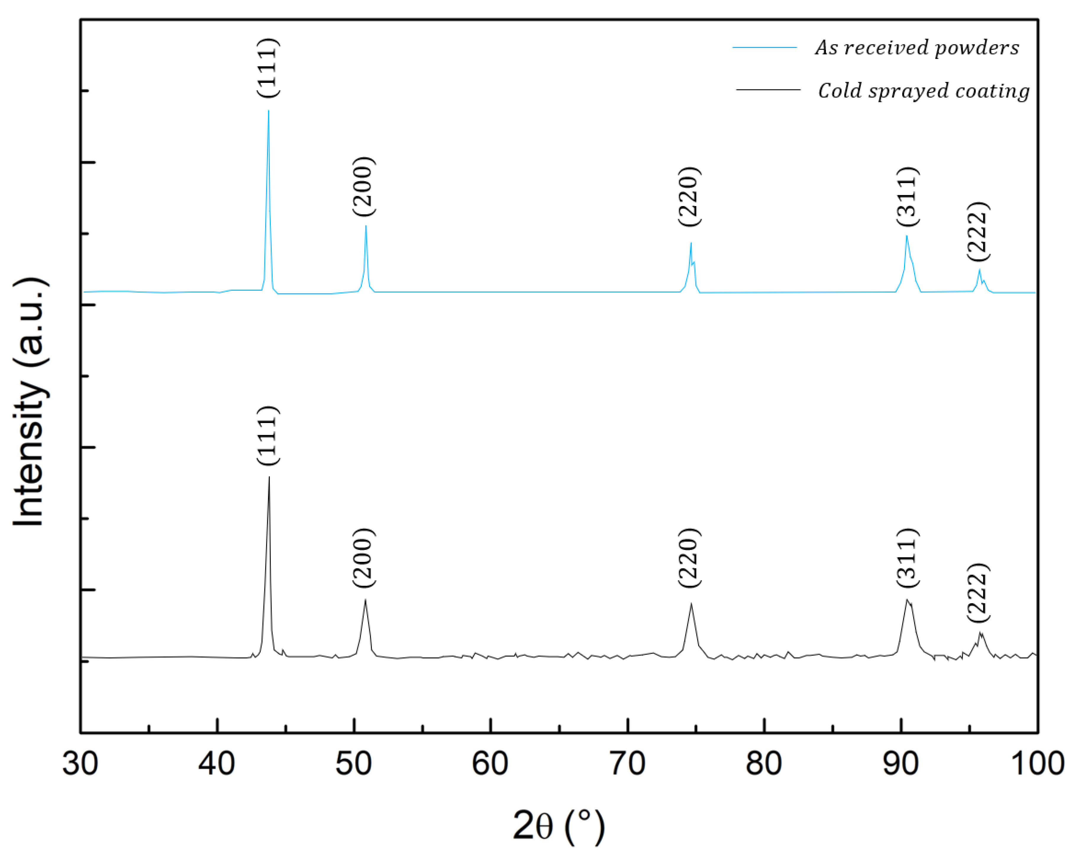
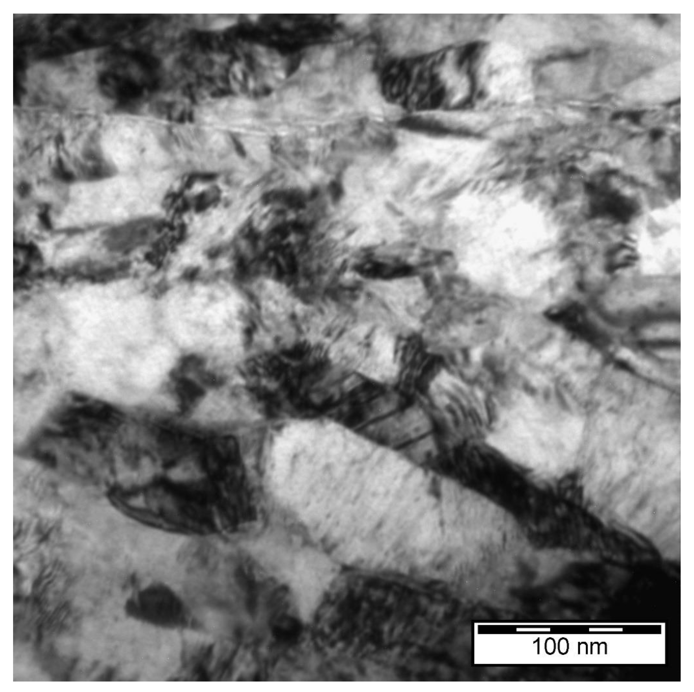
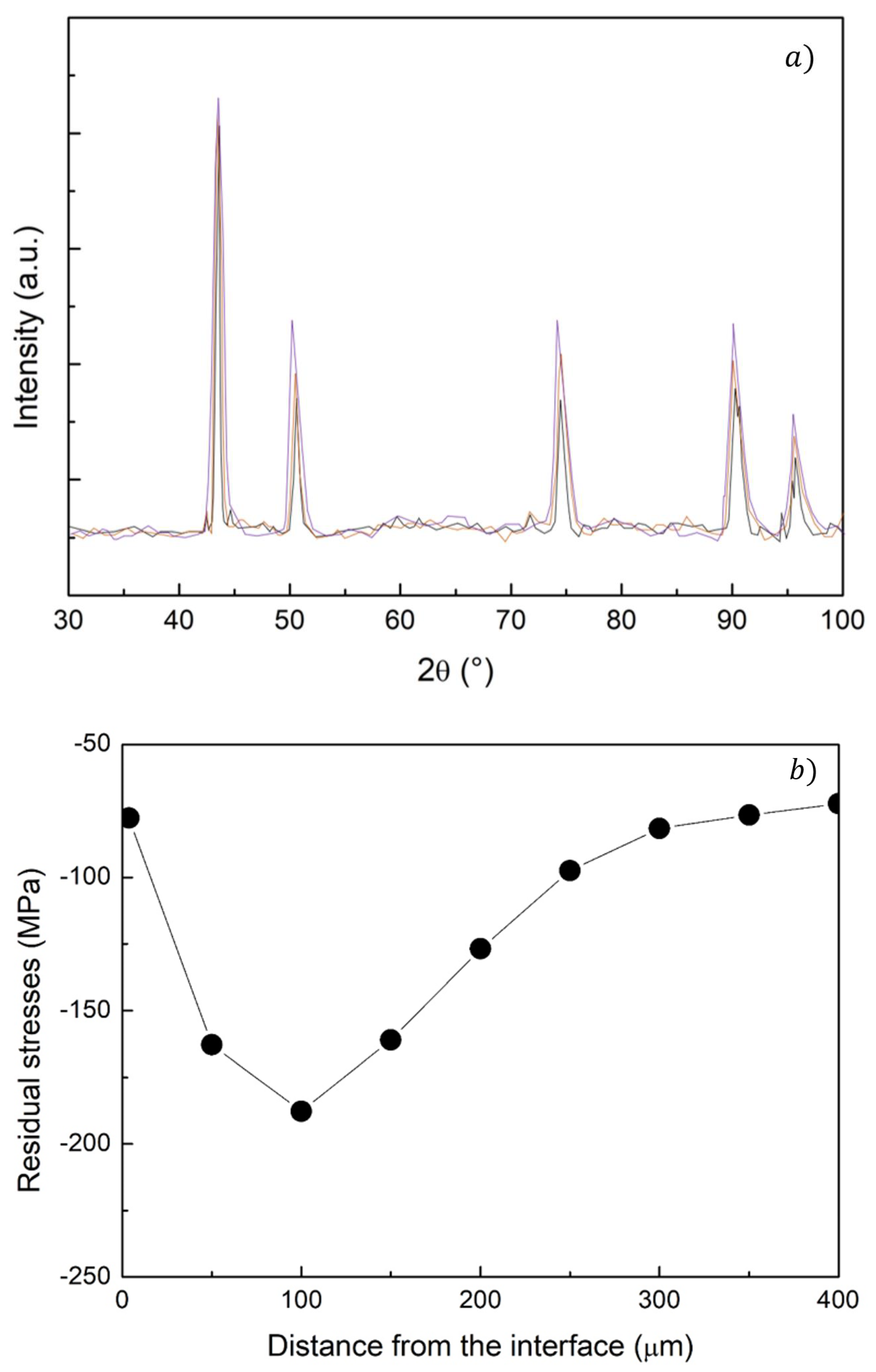
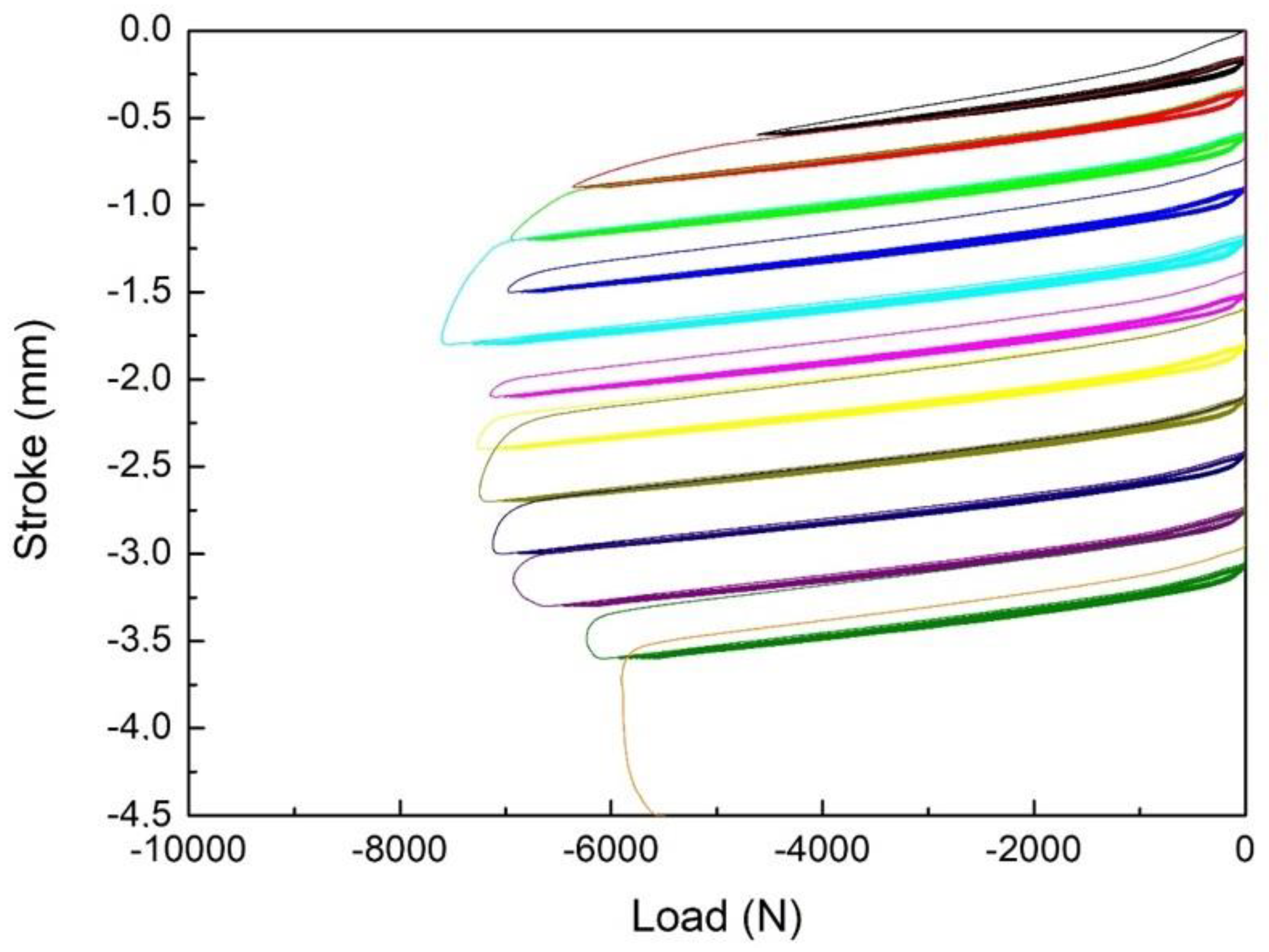
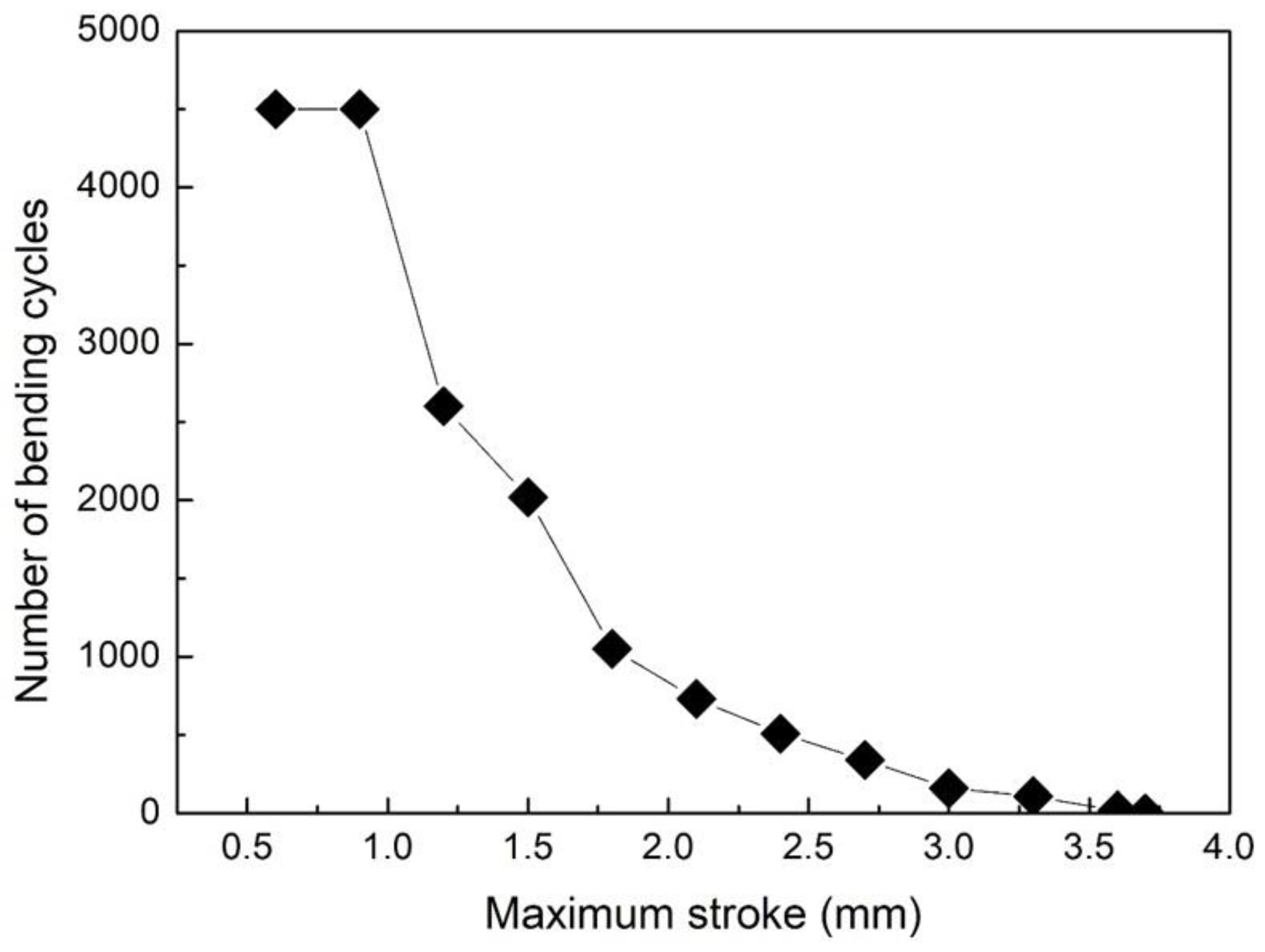
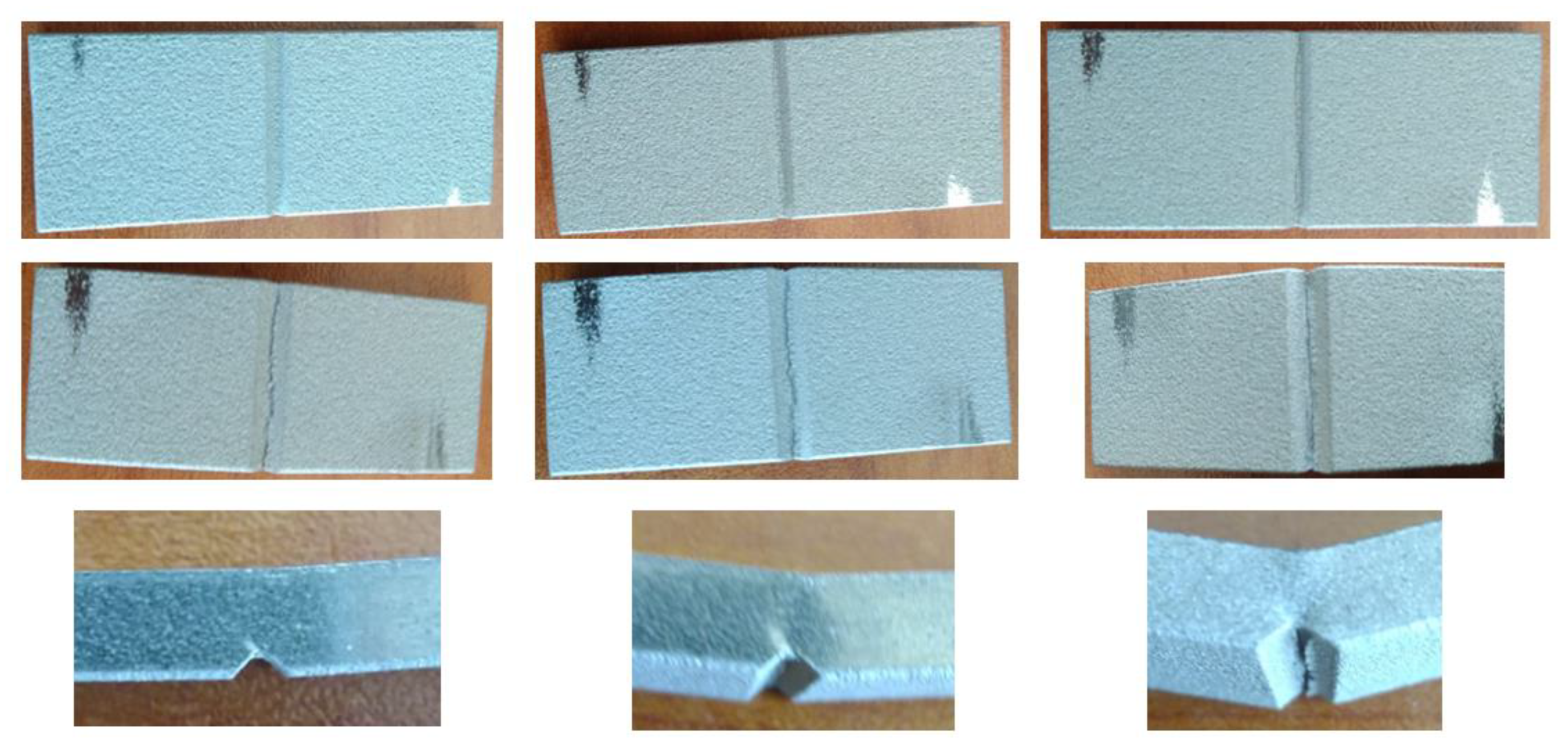
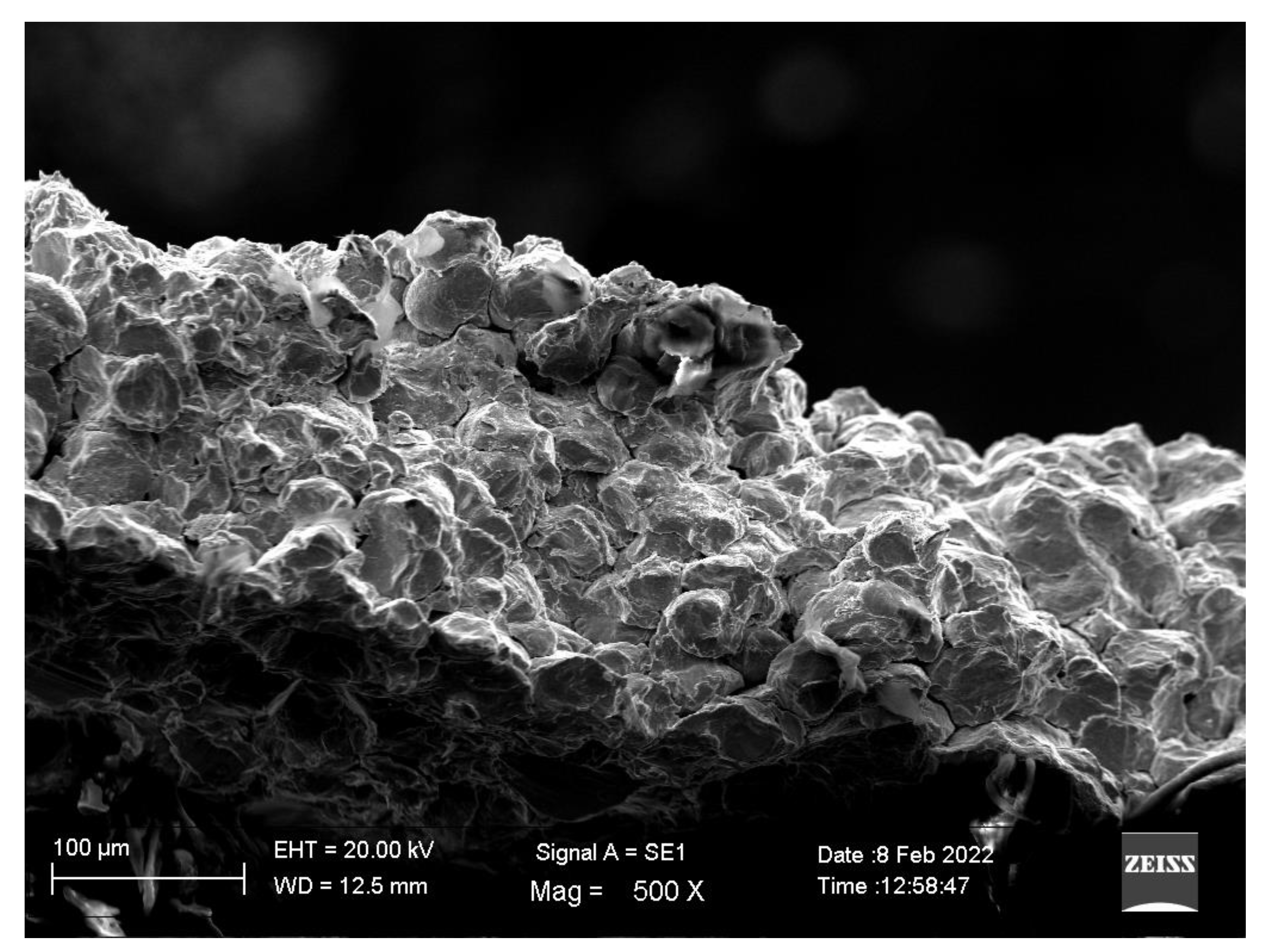
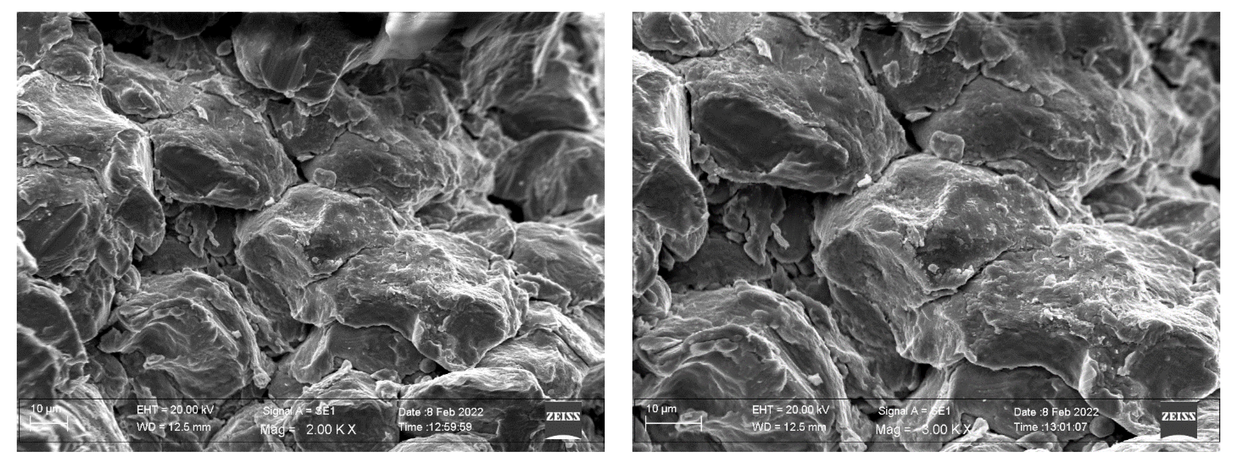
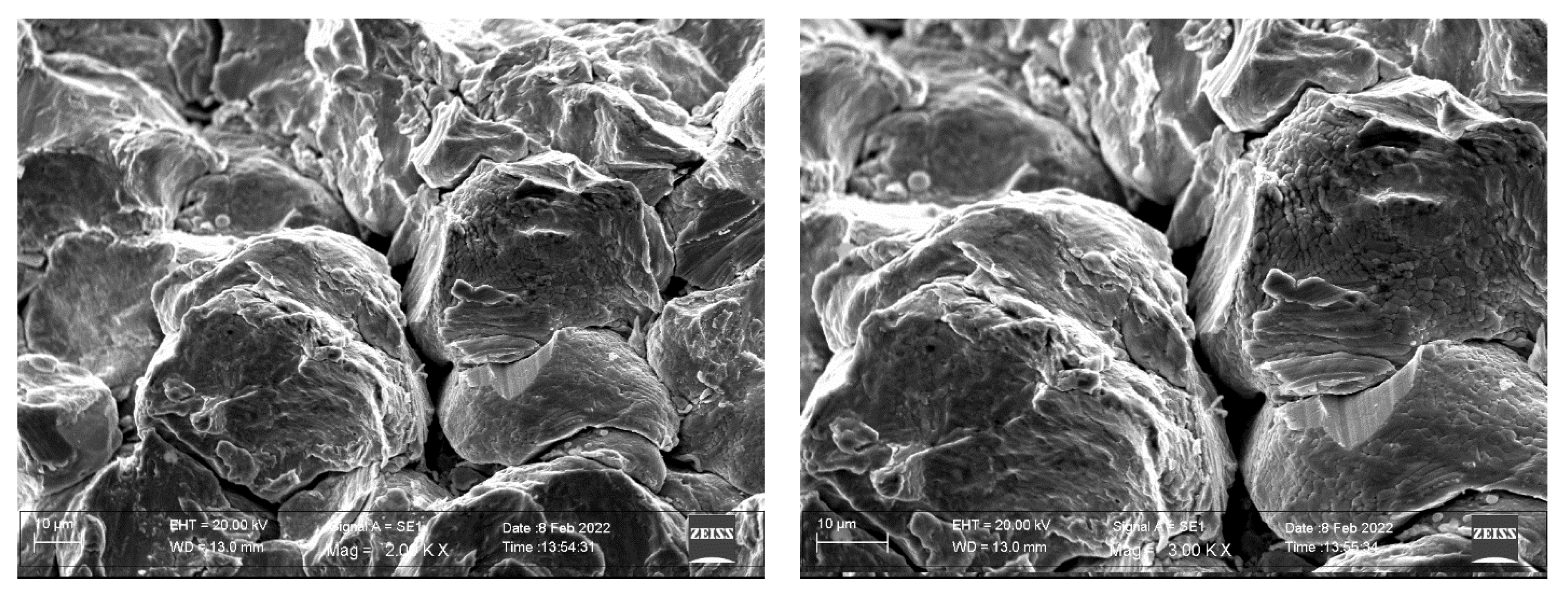
3. Results and Discussion

The employed particles are shown in Figure 2. They were characterized by a very narrow size [9]. The mean particle size was 32 μm with a d10 of 19.56 μm and d80 of 52 μm.
In the figure, the dendritic structure of the employed particles can be highlighted. The hardness of these particles was 1.5 GPa [9]. The average grain size of the as-received particles was 1.37 μm [45].
The cold-sprayed coating is shown in Figure 3.
The coating appeared to be characterized by low porosity (<1%) with no voids at the coating‐substrate interface. Coatings were deposited with a maximum thickness of 500 μm. Upon impact, cold-sprayed particles modified their initial spherical shape into a pancake-like one. This was accompanied by a pronounced flattening ratio that favored interparticle locking and a reduction in void formation. Once processing parameters were not sufficient to induce this pronounced flattening of the particles, an increase in the coating porosity was recorded [37]. Usually, high flattening ratios are also responsible for the good bonding of the coating to the substrate. On the contrary, if processing parameters are not able to provide high plastic deformation for the impacting particles, low adiabatic shear instability is experienced, and insufficient metallurgical bonding is achieved. In this view, flattening and reduced porosity are favored by employing higher temperatures during spraying [46]. Porosity levels are fundamental for the fatigue behavior of the coatings because pores can become crack nucleation sites by reducing the fatigue life of the coated components.
By revealing the aspect of the splatted particles, we measured the flattening ratio at different distances from the substrate as the width-to-height ratio for each single splat (Figure 4a). The variation of the flattening ratio as a function of the distance from the substrate is shown in Figure 4b.
With an increase in the particle distance from the substrate, the flattening ratio decreased toward the top layers. In fact, as the first particles splatted on the substrate, they were continuously deformed by the further impacted ones and continued to deform, producing a peening effect. This contributed to additional deformation and then to increased flattening [47,48]. These increased deformation levels are also related to the residual stresses that are expected to be higher in the regions close to the interface with the substrate. This behavior is also related to the substrate material; in fact, for hard substrates, the impacting particles experience more severe deformation with increased flattening and increased residual stress accumulation. In the case of softer substrates, the energy that is transferred to the bulk increases; as a consequence, lower deformation levels are experienced by the particles. This is accompanied by a decrease in the residual stress accumulated by the coating [49]. This behavior is strictly linked to the particle deformation behavior, depending on the substrate and on the particle hardness, in fact, the deformation mode of the splatting material can shift from adiabatic shear instability to interface instability [16,17]. This is related to the energy behavior during impact that governs the coating formation and its adhesion to the substrate. It contemporarily activates the mechanisms leading to bonding and to the reduction in porosity of the coating. The factors influencing the deformation of the sprayed particles are their velocity and the gas temperature. If the velocity is too high, particles can erode the substrate or the previously deposited particles, leading to the undesired phenomenon of low deformation. Exceeding the level of the gas temperature can lead to a decrease in the particle flow stress with a drop in the plastic work, despite particle deformation exponentially increasing with the increase in temperature. As a matter of fact, an optimal balance must be provided between the impact velocity and the gas temperature [50]. For the present study, processing conditions (gas temperature, particles dimensions, particles velocity) allowed for severe plastic deformation upon impact with a high flattening ratio. Consequently, this was expected to introduce high residual stress levels in the coating [51]. In this way, it was possible to improve the fatigue performance of the coatings despite this behavior being related to the absolute residual stress levels, as well as to their profile along the coating [52]. Residual stress is also responsible for the high adhesion strength to the substrate if high levels are reached in the regions close to the interface with the substrate [53].
The XRD profiles of the as-received particles and of the coating are shown in Figure 5. The XRD peaks of both the as-received powders and the as-sprayed coatings revealed that the face-centered cubic structure was retained after severe plastic deformation of the material. In addition, peak broadening was observed for the as-sprayed coating; this can be attributed to the residual strain induced in the material upon impact. This aspect is more precisely described during the discussion about the residual stress measurements along the coating thickness.
The coating microstructure characterized through transmission electron microscopy revealed grain refinement due to the severe plastic deformation experienced by the particles during splatting (Figure 6).
Figure 6 reveals a very fine microstructure with the main grains axes all oriented in a direction perpendicular to the spray direction. The microstructure observed in Figure 6 confirms the well-known phenomenon of recrystallization taking place in cold-spray materials during processing.
The broadening of the peaks revealed the induction of residual stresses in the coating as a consequence of the cold-spray processing. The XRD peaks at different levels from the coating top surface, revealed by removing very thin layers before each measurement, allowed for the definition of the residual stress profile as a function of the coating thickness (Figure 7). The residual stresses in the same direction of the spray are shown in Figure 7b.
As it can be observed by Figure 7b, compressive residual stresses were induced in the coating. The maximum compressive residual stresses were around 200 MPa very close to the substrate. The magnitude of the stresses decreased toward the top of the coating and toward the substrate. This profile is believed to provide good fatigue properties of the coating because of the intense residual stresses and the high adhesion of the coating to the substrate [9]. High residual stresses take place with rapid cooling of the sprayed material after severe plastic deformation upon impact [54]. This leads to the well-known phenomenon of shock loading with a consequent ultrahigh strain rate, leading to low heat dissipation [55]. In general, the residual stress development among splats is very complex, related to complex combinations of temperature, time-dependent localized deformation, temperature effects and defects, and thermal stress relaxation [56]. Here, all mechanisms leading to the induction of the compressive residual stress state were recognized. They were related to the elastoplastic deformation of the substrate and the particles (local compressive), to the full plastification of the substrate and the particles (similar to shot peening), and to the particle grain refinement and high dislocation density (local micro residual stresses). Depending on how these mechanisms evolve and how they separately contribute to the stress accumulation, the residual stress profile and characteristics can largely be modified.
The main effect of residual stresses on the fatigue behavior of the coatings is delamination retardation as a result of good adhesion to the substrate [57]. This is mainly attributed to the role of cold-sprayed particles in decreasing the tensile residual strains and increasing the compressive strains in the radial direction. This aspect is amplified by the increase in the gas temperature; this, in fact, leads to an increased flattening ratio and then improved uniform plastic deformation [58], especially in the case of very hard sprayed particles [59].
The nanoindentation hardness as a function of the distance from the substrate is shown in Figure 8.
The coating’s hardness decreased from 3.8 GPa close to the coating‐substrate interface to 2 GPa on the coating surface. During cold spraying, many hardening mechanisms take place during the adiabatic shear, such as grain local nanostructuring, work hardening, dynamic precipitation, and dispersion strengthening, depending on the impact energy density, which is related to the process parameters, the particle dimensions, and the intrinsic particle strength [60]. An additional contribution to the hardening, highlighted by the hardness profile, is given by the peening effect of the particles impacting the previously deposited ones. Another contribution is due to the more pronounced grain refinement in the zones close to the substrate surface [61].
In general, the fatigue behavior of cold-sprayed coatings is difficult to investigate because of the reduced volume with respect to the substrate [62,63]. In addition, many variables are related to the sample geometry, as well as to the loading mode [64]. In addition, the related fracture mechanisms are not conclusive; some studies focused on the aspect that cracks nucleate mainly in correspondence with the coating voids [65]. Other scientific evidence has indicated that, depending on the substrate’s surface preparation, fatigue damage takes place in correspondence with the surface flaws [66]. Many studies converged on the main conclusion that cold-spray coatings tend to improve the fatigue life of the coated samples [67,68,69]. In general, the deformation mode and the effect on fatigue life are due to the material pair, process parameters, and surface preparation [70].
In the present study, the cyclic behavior of the coatings was evaluated through three-point bending tests conducted at various levels of the maximum stroke. The load versus stroke curves for different maximum deformation imposed on the samples during cyclic bending are shown in Figure 9.
Cracks were all located in the zone of maximum bending and maximum stress concentration (the center of the notch), with the main central crack opening upon increasing the maximum load and the number of cycles. In our previous study [37], the coating ductility behavior under monotonic or cyclic bending was related to the number of cracks produced on the surface before the coating delamination. In the present case, the main crack nucleated in correspondence with the center of the notch for all maximum deformations imposed during tests. This was mainly due to the fact that cyclic loading led to the relaxation of residual stresses in the zone of maximum stress concentration. As a consequence, residual stresses decreased because the dislocations induced by cyclic loading converted the strain energy of macro residual strain into plastic strain. This took place overcoming a given critical value of the applied load, and its effect increased with the applied strain.
Then, various cyclic tests were conducted at different constant maximum strokes, and the tests were interrupted in order to observe the appearance of the first crack, the number of cycles for this damage initiation was recorded per each test. The summary is shown in Figure 10 where the maximum stroke is plotted as a function of the number of cycles until the first crack appearance.
As expected, the first crack nucleated at a lower number of bending cycles as the maximum stroke increased.
The aspects of the coating tested at the maximum stroke of 1.2 mm for different cycles are shown in Figure 11.
The crack nucleated in the center of the notch and then propagated toward the coating thickness up to final delamination. Very few papers provided a conclusive explanation of this decoherent behavior of cold-spray coatings. A highly accepted model considers the adhesion energy to cause failure at the interface [53]. This energy is released at the interface upon cyclic loading. If the strain energy release rate is lower than the adhesion energy of the coating, then the propagating crack will transition from the coating into the substrate. Conversely, if the strain energy release rate is higher than the adhesion energy, the propagating crack will interact with the interface layer, and debonding of the coating from the substrate may occur. This is due to the behavior of the coating approaching the interface; as a consequence of the material discontinuity, the crack intensity is modified, and the crack moves along the substrate–coating interface [71]. As a matter of fact, the mechanism of coating decohesion is very similar to that reported in [54] even if, in the present case, cyclic loading was performed in a three-point bending test instead of a four-point bending test. As a matter of fact, crack initiation took place on the surface and then led to branching with consequent coating layer spallation. As shown by the fracture surface observations, cracks initiated on the surface in correspondence with the void locations or in correspondence with defects due to undeformed particles that remained embedded in the coating layer.
At higher magnification, it was possible to follow the damage evolution acting on the coating during cyclic bending (Figure 12).
Compared with Ni-based superalloys with notched substrate described in [38], it is clear that the present coating revealed a lower density of cracks before delamination.
In addition, in [37], multiple delaminations were observed in the sample, while, in the present case, the main crack governed the coating delamination in its vicinity. This behavior was also explained as the optimal adhesion experienced by the coating thanks to the selected processing parameters. In the case of the HEAs employed in the present paper, higher temperature and higher pressure were employed for the coating deposition. Thus, it is reasonable that particles impacted with increased velocity, experiencing a more pronounced severe plastic deformation leading to higher splat and better adhesion to the substrate because of the enhanced peening effect. This was confirmed by the increased flattening ratio experienced by the particles of the present work and described in Figure 3. Therefore, in conclusion, the employed process parameters (1100 °C and 7 MPa) led to a more compact coating with remarkable particle deformation upon impact with a consequent high adhesion of the coating to the substrate and high residual stress levels. This led to a fatigue behavior of the coating completely different from that revealed by particles with similar strength and dimensions employed to produce cold-sprayed coatings obtained at lower temperature and pressure. Hence, even if a more macroscopic brittleness could be revealed, a better coating adhesion was obtained, especially under cyclic loading. This was also due to the high temperature employed in the present study that led to optimal adhesion of the coatings to the substrate [55]. In fact, as the deposition temperature increased, multiple cracks on the coating surface tended to disappear, and only one main crack governed the coating fracture behavior. Thus, high deposition temperatures led to higher adhesion and better performance in terms of crack initiation, as demonstrated in [13,34,37].
The fracture surface of the notched sample after rupture is shown in Figure 13.
Here, the main fracture mechanism was due to particle‐particle decohesion with local ductility features experienced at the particle‐particle interfaces (Figure 14).
The fatigue crack mechanism is dependent on the applied stress and the crack size in comparison with the material microstructural features [72]. In many cases, the shift from transparticular to interparticular crack propagation depends on the stress intensity. This is attributed to the change in the dimension of the plastic zone ahead of the crack propagation tip. In this case, weaker particles and more microvoids can be encountered along the crack propagation path, leading to particle‐particle decohesion instead of interparticle fracture. Therefore, this general behavior can lead to very brittle coating behavior at low intensity; otherwise, more ductile features can be observed at low intensities. This has been demonstrated by post-spray heat treatments leading to an increase in coating ductility with consequent decreased fatigue crack growth, thanks to improved interparticle bonding [35]. This is also due to basic powder metallurgy mechanisms leading to a decrease in the void effect on the local diffusion around the microvoids formed during the spray operations. In addition, the different precipitation states of heat-treated alloys can act as a barrier to the crack propagation [73]. Furthermore, a finer microstructure with an optimal deposition can act as a crack retardant. In general, for the same powders, cold-spray coatings show a finer microstructure due to the higher impact velocity as a consequence of the more severe plastic deformation upon impact. In this case, a compact coating coupled with a fine microstructure can provide a greater number of grain boundaries impeding the slip during loading [74]. This is demonstrated by a more faceted fracture surface aspect due to the increased resistance of each particle.
Many particles showed the formation of local striations typical of the cyclic loading the samples were subjected to (Figure 15).
On the contrary, particles impacting with lower velocity led to coatings with decreased bonding strength, fracture toughness, and a very brittle fracture surface [75]. Again, the fracture behavior was governed by the particle‐particle bonding strength. This was governed by the shear instability upon impact that led to heat being retained by the particles, leading to an improvement of the particle‐particle bond strength.
In this case, the main fracture mechanism was due to particle‐particle decohesion. The main difference is that, as the maximum stroke increased, the formation of large voids on the surface increased (Figure 16).
By observing the zones of the fracture surface where voids were individuated, it should be highlighted that these voids tended to form where particles appeared with their original aspect (Figure 17).
Hence, in these zones, particles experienced low deformation, while particle‐particle interlocking and local cohesion did not take place. These zones had low resistance to loading and, as a consequence, large voids were formed.
Accordingly, even if local fatigue mechanisms could be individuated on each particle surface, particle‐particle decohesion also took place in the case of largely deformed particles (Figure 18).
This behavior was due to the microstructure of the starting particles and to their behavior upon slatting. In fact, variation in the powder particle microstructure can lead to different impact physics and ultimate impact morphology [76]. In fact, the morphology of deformed particles can shift from a perfect half-sphere with radial jetting zones to the same half-sphere with irregular protuberances to triangular shapes with threefold symmetry to square-like shapes with fourfold symmetry. Obviously, as the morphology changes, so do the particle‐particle bonding and the overall coating resistance. This variation in the morphology is dependent on the starting particle microstructure, as it moves from an equiaxed microstructure, the deformed particle morphology shifts from a perfect half-sphere with radial jets toward other morphologies. Therefore, as the microstructure moves from an equiaxed grain, the particle‐particle adhesion surfaces are reduced, voids form, and the fracture surface aspect appears more brittle. In this view, the impact and bonding behavior of particles and the consequent fracture aspect can also largely vary for a nonuniform grain size and shape distribution.
Another fundamental factor is represented by the effect on crack initiation and propagation related to the properties of the feedstock powders [77,78,79]. Crack initiation as transparticle fracture is dependent on the splatting of the particles; at high loads, high-quality splatted powders reveal a mixture of interparticular and trasnparticular fracture aspects during crack propagation. This reveals the quality of the particle‐particle bonding at high deformations. As a matter of fact, only strongly bonded particle‐particle interfaces are able to transfer the load producing local plastic deformation indicated by the occurrence of nonbrittle features on the fracture surface. This is demonstrated by other scientific studies where crack propagation was improved because of proper post-deposition heat treatments leading to an increase in particle‐particle bonding because of local diffusion processes taking place at the particle‐particle interfaces [72]. This was confirmed by crack initiation and growth behavior of aluminum alloys where the crack initiation is accompanied by a flat aspect of the crack path, which becomes more tortuous as the crack propagates toward final failure. This change from transparticular to mixed interparticular and transparticular crack propagation is in correspondence with the increase in the local loading conditions as the crack propagates. This has also been observed in other hard materials such as cold-sprayed metal matrix composites where brittleness was much more pronounced with respect to the unreinforced base materials [75], as well as in stainless-steel cold-spray deposits [77]. In this case, it can be underlined that both grain size (due to particle splatting) and strain hardening (due to loading) are responsible for the transparticular deformation.

4. Conclusions

Cold-spray coatings were produced at 1100 °C and 7 MPa, obtaining FeCoCrNiMn equiatomic high-entropy alloy deposits with very low porosity and high hardness, and with a thickness of 500 μm. This was due to the large flattening ratio induced in the splatted particles thanks to the employed processing parameters. This demonstrates that the tuned employed process parameters were optimally settled for this specific high-entropy alloy on the employed substrate. Obviously, the flattening ratio was more pronounced in those regions very close to the substrate where the severe plastic deformation of the sprayed material increased because of the continuous peening effect due to further impacting particles.
The XRD analyses of the as-received powders and of the as-sprayed coatings revealed the retention of the face-centered cubic structure of the high-entropy alloy. The broadening of the XRD peaks revealed through layer-by-layer measurements allowed defining the residual stress profile along the coating with maximum compressive stresses close to 200 MPa at a distance of 100 μm from the substrate–coating interface. The residual stress profile appeared optimal for the fatigue strength of the coatings with compressive characteristics in the inner layers.
The three-point bending cyclic tests, performed at a fixed value of the maximum stroke on V-notched substrates, allowed defining the number of cycles before the appearance of the first surface crack for a given value of the maximum imposed stroke. As expected, the first surface crack nucleated at a lower number of cycles as the maximum stroke decreased. The crack aspect revealed a good adhesion of the coating to the substrate.
The fracture mechanisms revealed a mixed brittleness character of the crack propagation path with local ductile and fatigue features revealed on the fracture surface. Cracks nucleated mainly at the surface defects with a mainly transparticular path at the first stages of deformation, whereas a mixed transparticular and interparticular fracture behavior was revealed by the fracture surface. It is believed that microvoids and undeformed splat particles were responsible for the acceleration of the crack propagation.

Author Contributions

Conceptualization, P.C., A.S., I.G.C. and A.P.; methodology, P.C. and G.B.; validation, P.C.; formal analysis, G.B., A.L., A.P. and A.S.; investigation, G.B., A.L., A.P. and A.S.; resources, P.C., and I.G.C.; data curation, P.C. and A.P.; writing—original draft preparation, P.C.; writing—review and editing, P.C.; supervision, P.C. and I.G.C.; project administration, P.C. and I.G.C.; funding acquisition, P.C. and I.G.C. All authors have read and agreed to the published version of the manuscript.

Funding

This research was funded by Agència de Gestió d’Ajuts Universitaris i de Recerca (Spain), grant number SGR 2017-01777 AGAUR and by Ministerio de Ciencia e Innovación (Spain), grant number PID 2020-115508RB-C21.

Institutional Review Board Statement

Not applicable.

Informed Consent Statement

Not applicable.

Data Availability Statement

Data will be available on request to the corresponding author.

Conflicts of Interest

The authors declare no conflict of interest.

References

  1. Yeh, J.-W.; Chen, S.-K.; Lin, S.-J.; Gan, J.-Y.; Chin, T.-S.; Shun, T.-T.; Tsau, C.-H.; Chang, S.-Y. Nanostructured high-entropy alloys with multiple principal elements: Novel alloy design concepts and outcomes. Adv. Eng. Mater. 2004, 6, 299–303. [Google Scholar] [CrossRef]
  2. Zhang, Y.; Zuo, T.T.; Tang, Z.; Gao, M.C.; Dahmen, K.A.; Liaw, P.K.; Lu, Z.P. Microstructures and properties of high-entropy alloys. Prog. Mater. Sci. 2014, 61, 1–93. [Google Scholar] [CrossRef]
  3. Miracle, D.B.; Senkov, O.N. A critical review of high entropy alloys and related concepts. Acta Mater. 2017, 122, 488–511. [Google Scholar] [CrossRef] [Green Version]
  4. Otto, F.; Dlouhý, A.; Somsen, C.; Bei, H.; Eggeler, G.; George, E.P. The influences of temperature and microstructure on the tensile properties of a CoCrFeMnNi high-entropy alloy. Acta Mater. 2013, 61, 5743–5755. [Google Scholar] [CrossRef] [Green Version]
  5. Gludovatz, B.; Hohenwarter, A.; Catoor, D.; Chang, E.H.; George, E.P.; Ritchie, R.O. A fracture-resistant high-entropy alloy for cryogenic applications. Science 2014, 345, 1153–1158. [Google Scholar] [CrossRef] [PubMed] [Green Version]
  6. Yazdani, N.; Toroghinejad, M.R.; Shabani, A.; Cavaliere, P. Effects of Process Control Agent Amount, Milling Time, and Annealing Heat Treatment on the Microstructure of AlCrCuFeNi High-Entropy Alloy Synthesized through Mechanical Alloying. Metals 2021, 11, 1493. [Google Scholar] [CrossRef]
  7. Moazzen, P.; Toroghinejad, M.R.; Cavaliere, P. Effect of Iron content on the microstructure evolution, mechanical properties and wear resistance of FeXCoCrNi high-entropy alloy system produced via MA-SPS. J. Alloy. Compd. 2021, 870, 159410. [Google Scholar] [CrossRef]
  8. Moazzen, P.; Toroghinejad, M.R.; Zargar, T.; Cavaliere, P. Investigation of hardness, wear and magnetic properties of NiCoCrFeZrx HEA prepared through mechanical alloying and spark plasma sintering. J. Alloy. Compd. 2022, 892, 161924. [Google Scholar] [CrossRef]
  9. Silvello, A.; Cavaliere, P.; Yin, S.; Lupoi, R.; Garcia Cano, I.; Dosta, S. Microstructural, Mechanical and Wear Behavior of HVOF and Cold-Sprayed High-Entropy Alloys (HEAs) Coatings. J. Therm. Spray Tech. 2022, 1–23. [Google Scholar] [CrossRef]
  10. Shi, Y.; Yang, B.; Liaw, P. Corrosion-Resistant High-Entropy Alloys: A Review. Metals 2017, 7, 43. [Google Scholar] [CrossRef] [Green Version]
  11. Qiu, Y.; Thomas, S.; Gibson, M.A.; Fraser, H.L.; Birbilis, N. Corrosion of high entropy alloys. Npj. Mater. Degrad. 2017, 1, 15. [Google Scholar] [CrossRef]
  12. Yin, S.; Cavaliere, P.; Aldwell, B.; Jenkins, R.; Liao, H.; Li, W.; Lupoi, R. Cold spray additive manufacturing and repair: Fundamentals and applications. Addit. Manuf. 2018, 21, 628–650. [Google Scholar] [CrossRef]
  13. Cavaliere, P.; Silvello, A. Crack Repair in Aerospace Aluminum Alloy Panels by Cold Spray. J. Therm. Spray Technol. 2017, 26, 661–670. [Google Scholar] [CrossRef]
  14. Cavaliere, P. Cold-Spray Coatings: Recent Trends and Future Perspectives; Springer International Publishing: Cham, Switzerland, 2018. [Google Scholar] [CrossRef]
  15. Assadi, H.; Gärtner, F.; Stoltenhoff, T.; Kreye, H. Bonding mechanism in cold gas spraying. Acta Mater. 2003, 51, 4379–4394. [Google Scholar] [CrossRef]
  16. Grujicic, M.; Zhao, C.L.; DeRosset, W.S.; Helfritch, D. Adiabatic shear instability based mechanism for particles/substrate bonding in the cold-gas dynamic-spray process. Mater. Des. 2004, 25, 681–688. [Google Scholar] [CrossRef]
  17. Grujicic, M.; Saylor, J.R.; Beasley, D.E.; DeRosset, W.S.; Helfritch, D. Computational analysis of the interfacial bonding between feed-powder particles and the substrate in the cold-gas dynamic-spray process. Appl. Surf. Sci. 2003, 219, 211–227. [Google Scholar] [CrossRef]
  18. Hassani-Gangaraj, M.; Veysset, D.; Champagne, V.K.; Nelson, K.A.; Schuh, C.A. Adiabatic shear instability is not necessary for adhesion in cold spray. Acta Mater. 2018, 158, 430–439. [Google Scholar] [CrossRef]
  19. Hassani-Gangaraj, M.; Veysset, D.; Nelson, K.A.; Schuh, C.A. In-situ observations of single micro-particle impact bonding. Scr. Mater. 2018, 145, 9–13. [Google Scholar] [CrossRef]
  20. Stoltenhoff, T.; Kreye, H.; Richter, H.J. An analysis of the cold spray process and its coatings. J. Therm. Spray Technol. 2002, 11, 542–550. [Google Scholar] [CrossRef]
  21. Moridi, A.; Hassani-Gangaraj, S.M.; Guagliano, M.; Dao, M. Cold spray coating: Review of material systems and future perspectives. Surf. Eng. 2014, 30, 369–395. [Google Scholar] [CrossRef]
  22. Luzin, V.; Spencer, K.; Zhang, M.-X. Residual stress and thermo-mechanical properties of cold spray metal coatings. Acta Mater. 2011, 59, 1259–1270. [Google Scholar] [CrossRef]
  23. Luo, X.; Li, C.; Shang, F.; Yang, G.; Wang, Y.; Li, C. High velocity impact induced microstructure evolution during deposition of cold spray coatings: A review. Surf. Coat. Technol. 2014, 254, 11–20. [Google Scholar] [CrossRef]
  24. Marzbanrad, B.; Jahed, H.; Toyserkani, E. On the evolution of substrate’s residual stress during cold spray process: A parametric study. Mater. Des. 2018, 138, 90–102. [Google Scholar] [CrossRef]
  25. Cavaliere, P.; Silvello, A. Fatigue behaviour of cold sprayed metals and alloys: Critical review. Surf. Eng. 2016, 32, 631–640. [Google Scholar] [CrossRef]
  26. Ghelichi, R.; MacDonald, D.; Bagherifard, S.; Jahed, H.; Guagliano, M.; Jodoin, B. Microstructure and fatigue behavior of cold spray coated Al5052. Acta Mater. 2012, 60, 6555–6561. [Google Scholar] [CrossRef]
  27. Moridi, A.; Hassani-Gangaraj, S.M.; Vezzú, S.; Trško, L.; Guagliano, M. Fatigue behavior of cold spray coatings: The effect of conventional and severe shot peening as pre-/post-treatment. Surf. Coat. Technol. 2015, 283, 247–254. [Google Scholar] [CrossRef]
  28. Dayani, S.B.; Shaha, S.K.; Ghelichi, R.; Wang, J.F.; Jahed, H. The impact of AA7075 cold spray coating on the fatigue life of AZ31B cast alloy. Surf. Coat. Technol. 2018, 337, 150–158. [Google Scholar] [CrossRef]
  29. Cavaliere, P.; Silvello, A. Processing conditions affecting residual stresses and fatigue properties of cold spray deposits. Int. J. Adv. MAnuf. Technol. 2015, 81, 1857–1862. [Google Scholar] [CrossRef]
  30. Tetráčková, K.; Kondás, J.; Guagliano, M. Mechanical Performance of Cold-Sprayed A357 Aluminum Alloy Coatings for Repair and Additive Manufacturing. J. Therm. Spray Technol. 2017, 26, 1888–1897. [Google Scholar] [CrossRef]
  31. Yandouzi, M.; Gaydos, S.; Guo, D.; Ghelichi, R.; Jodoin, B. Aircraft Skin Restoration and Evaluation. J. Therm. Spray Technol. 2014, 23, 1281–1290. [Google Scholar] [CrossRef]
  32. Bagherifard, S.; Guagliano, M. Fatigue performance of cold spray deposits: Coating, repair and additive manufacturing cases. Int. J. Fatigue 2020, 139, 105744. [Google Scholar] [CrossRef]
  33. Sample, C.M.; Champagne, V.K.; Nardi, A.T.; Lados, D.A. Factors governing static properties and fatigue, fatigue crack growth, and fracture mechanisms in cold spray alloys and coatings/repairs: A review. Addit. Manuf. 2020, 36, 101371. [Google Scholar] [CrossRef]
  34. Cavaliere, P.; Silvello, A. Finite element analyses of pure Ni cold spray particles impact related to coating crack behaviour. Surf. Eng. 2018, 34, 361–368. [Google Scholar] [CrossRef]
  35. Cavaliere, P.; Perrone, A.; Silvello, A. Fatigue behaviour of Inconel 625 cold spray coatings. Surf. Eng. 2018, 34, 380–391. [Google Scholar] [CrossRef]
  36. Silvello, A.; Cavaliere, P.; Rizzo, A.; Valerini, D.; Dosta Parras, S.; Garcia Cano, I. Fatigue Bending Behavior of Cold-Sprayed Nickel-Based Superalloy Coatings. J. Therm. Spray Technol. 2019, 28, 930–938. [Google Scholar] [CrossRef] [Green Version]
  37. Cavaliere, P.; Silvello, A.; Cinca, N.; Canales, H.; Dosta, S.; Garcia Cano, I.; Guilemany, J.M. Microstructural and fatigue behavior of cold sprayed Ni-based superalloys coatings. Surf. Coat. Technol. 2017, 324, 390–402. [Google Scholar] [CrossRef]
  38. Xu, Y.; Li, W.; Qu, L.; Yang, X.; Song, B.; Lupoi, R.; Yin, S. Solid-state cold spraying of FeCoCrNiMn high-entropy alloy: An insight into microstructure evolution and oxidation behavior at 700–900 °C. J. Mater. Sci. Technol. 2021, 68, 172–183. [Google Scholar] [CrossRef]
  39. Ahn, J.E.; Kim, Y.K.; Yoon, S.H.; Lee, K.A. Tuning the Microstructure and Mechanical Properties of Cold Sprayed Equiatomic CoCrFeMnNi High-Entropy Alloy Coating Layer. Met. Mater. Int. 2021, 27, 2406–2415. [Google Scholar] [CrossRef]
  40. Rojas, D.F.; Li, H.; Orhan, O.K.; Shao, C.; Hogan, J.D.; Ponga, M. Mechanical and microstructural properties of a CoCrFe0.75NiMo0.3Nb0.125 high-entropy alloy additively manufactured via cold-spray. J. Alloy. Compd. 2022, 893, 162309. [Google Scholar] [CrossRef]
  41. Kim, Y.-K.; Ham, G.-S.; Kim, H.S.; Lee, K.-A. High-cycle fatigue and tensile deformation behaviors of coarse-grained equiatomic CoCrFeMnNi high-entropy alloy and unexpected hardening behavior during cyclic loading. Intermetallics 2019, 111, 106486. [Google Scholar] [CrossRef]
  42. Lu, Y.P.; Gao, X.; Jiang, L.; Chen, Z.; Wang, T.; Jie, J.; Kang, H.; Zhang, Y.; Guo, S.; Ruan, H.; et al. Directly cast bulk eutectic and near-eutectic high entropy alloys with balanced strength and ductility in a wide temperature range. Acta Mater. 2017, 124, 143–150. [Google Scholar] [CrossRef] [Green Version]
  43. Brocq, M.L.; Goujon, P.-A.; Monnier, J.; Villeroy, B.; Perrire, L.; Pirs, R.; Garchin, G. Microstructure and mechanical properties of a CoCrFeMnNi high entropy alloy processed by milling and spark plasma sintering. J. Alloy. Comp. 2019, 780, 856–865. [Google Scholar] [CrossRef]
  44. Ghelichi, R.; Bagherifard, S.; Donald, D.M.; Brochu, M.; Jahed, H.; Jodoin, B.; Guagliano, M. Fatigue strength of Al alloy cold sprayed with nanocrystalline powders. Int. J. Fatigue 2014, 65, 51–57. [Google Scholar] [CrossRef]
  45. Yu, P.; Fan, N.; Zhang, Y.; Wang, Z.; Li, W.; Lupoi, R.; Yin, S. Microstructure evolution and composition redistribution of FeCoNiCrMn high entropy alloy under extreme plastic deformation. Mater. Res. Lett. 2022, 10, 124–132. [Google Scholar] [CrossRef]
  46. Assadi, H.; Kreye, H.; Gartner, F.; Klassen, T. Cold spraying a materials perspective. Acta Mater. 2016, 116, 382–407. [Google Scholar] [CrossRef] [Green Version]
  47. Wong, W.; Vo, P.; Irissou, E.; Ryabinin, A.N.; Legoux, J.-G.; Yue, S. Effect of particle morphology and size distribution on cold-sprayed pure titanium coatings. J. Therm. Spray Technol. 2013, 22, 1140–1153. [Google Scholar] [CrossRef]
  48. Assadi, H.; Schmidt, T.; Richter, H.; Kliemann, J.O.; Binder, K.; Gärtner, F.; Klassen, T.; Kreye, H. On parameter selection in cold spraying. J. Therm. Spray Technol. 2011, 20, 1161–1176. [Google Scholar] [CrossRef]
  49. Spencer, K.; Luzin, V.; Matthews, N.; Zhang, M.X. Residual stresses in cold spray al coatings: The effect of alloying and of process parameters. Surf. Coat. Technol. 2012, 206, 4249–4255. [Google Scholar] [CrossRef]
  50. Eason, P.D.; Fewkes, J.A.; Kennett, S.C.; Eden, T.J.; Tello, K.; Kaufman, M.J.; Tiryakioglu, M. On the characterization of bulk copper produced by cold gas dynamic spray processing in as fabricated and annealed conditions. Mater. Sci. Eng. A 2011, 528, 8174–8178. [Google Scholar] [CrossRef]
  51. Cavaliere, P.; Perrone, A.; Silvello, A. Crystallization evolution of cold sprayed pure Ni coatings. J. Therm. Spray Technol. 2016, 25, 1158–1167. [Google Scholar] [CrossRef]
  52. Singh, R.; Schruefer, S.; Wilson, S.; Gibmeier, J.; Vassen, R. Influence of coating thickness on residual stress and adhesion-strength of cold-sprayed Inconel 718 coatings. Surf. Coat. Technol. 2018, 350, 64–73. [Google Scholar] [CrossRef]
  53. White, B.C.; Story, W.A.; Brewer, L.N.; Jordon, J.B. Fracture mechanics methods for evaluating the adhesion of cold spray deposits. Eng. Fract. Mech. 2019, 205, 57–69. [Google Scholar] [CrossRef]
  54. Lin, E.; Chen, Q.; Ozdemir, O.C.; Champagne, V.K.; Müftü, S. Effects of Interface Bonding on the Residual Stresses in Cold-Sprayed Al-6061: A Numerical Investigation. J. Therm. Spray Technol. 2019, 28, 472–483. [Google Scholar] [CrossRef]
  55. Jafarlou, D.M.; Ferguson, G.; Tsaknopoulos, K.L.; Chuang, A.C.; Nardi, A.; Cote, D.; Champagne, V.; Grosse, I.R. Structural integrity of additively manufactured stainless steel with cold sprayed barrier coating under combined cyclic loading. Addit. Manuf. 2020, 35, 101338. [Google Scholar] [CrossRef]
  56. Luzin, V.; Kirstein, O.; Zahiri, S.H.; Fraser, D. Residual Stress Buildup in Ti Components Produced by Cold Spray Additive Manufacturing (CSAM). J. Therm. Spray Technol. 2020, 29, 1498–1507. [Google Scholar] [CrossRef]
  57. Cizek, J.; Matejkova, M.; Dlouhy, I.; Siska, F.; Kay, C.M.; Karthikeyan, J.; Kuroda, S.; Kovarik, O.; Siegl, J.; Loke, K.; et al. Influence of cold-sprayed, warm-sprayed, and plasma-sprayed layers deposition on fatigue properties of steel specimens. J. Therm. Spray Technol. 2015, 24, 758–768. [Google Scholar] [CrossRef] [Green Version]
  58. Fardan, A.; Berndt, C.C.; Ahmed, R. Numerical modelling of particle impact and residual stresses in cold sprayed coatings: A review. Surf. Coat. Technol. 2021, 409, 126835. [Google Scholar] [CrossRef]
  59. Seraj, R.A.; Abdollah-zadeh, A.; Dosta, S.; Canales, H.; Assadi, H.; Cano, I.G. The effect of traverse speed on deposition efficiency of cold sprayed Stellite 21. Surf. Coat. Technol. 2019, 366, 24–34. [Google Scholar] [CrossRef]
  60. Gao, P.-H.; Li, C.-J.; Yang, G.-J.; Li, Y.-G.; Li, C.-X. Influence of substrate hardness on deposition behavior of single porous WC-12Co particle in cold spraying. Surf. Coat. Technol. 2008, 203, 384–390. [Google Scholar] [CrossRef]
  61. Champagne, V.K.; Helfritch, D.J.; Trexler, M.D.; Gabriel, B.M. The effect of cold spray impact velocity on deposit hardness. Modell. Simul. Mater. Sci. Eng. 2010, 18, 65011. [Google Scholar] [CrossRef]
  62. Schmidt, T.; Gaertner, F.; Kreye, H. New developments in cold spray based on higher gas and particle temperatures. J. Therm. Spray Technol. 2006, 15, 488–494. [Google Scholar] [CrossRef]
  63. Moridi, A.; Hassani-Gangaraj, S.M.; Guagliano, M. On fatigue behavior of cold spray coating. MRS Online Proc. Library 2014, 1650, 503. [Google Scholar] [CrossRef]
  64. Bagherifard, S.; Monti, S.; Zuccoli, M.V.; Riccio, M.; Kondás, J.; Guagliano, M. Cold spray deposition for additive manufacturing of freeform structural components compared to selective laser melting. Mater. Sci. Eng. A 2018, 721, 339–350. [Google Scholar] [CrossRef]
  65. Yamazaki, Y.; Fukanuma, H.; Ohno, N. Anisotropic mechanical properties of the free-standing cold sprayed SUS316 coating and the effect of the post-spray heat treatment on it. J. Jpn. Therm. Spray. Soc. 2016, 53, 91–95. [Google Scholar]
  66. Price, T.S.; Shipway, P.H.; McCartney, D.G. Effect of cold spray deposition of a titanium coating on fatigue behavior of a titanium alloy. J. Therm. Spray Technol. 2006, 15, 507–512. [Google Scholar] [CrossRef]
  67. Xiong, Y.; Zhang, M.-X. The effect of cold sprayed coatings on the mechanical properties of AZ91D magnesium alloys. Surf. Coat. Technol. 2014, 253, 89–95. [Google Scholar] [CrossRef] [Green Version]
  68. Shi, Z.-C.; Zhang, X.-Y.; Chen, H.; Ding, F.-Z.; Yu, B.; Tang, Z.-H.; Lu, F. Properties of cold spray Al/Zn coatings on high-strength steel. J. Mater. Eng. 2015, 43, 14–19. [Google Scholar] [CrossRef]
  69. Ševeček, M.; Krejčí, J.; Shahin, M.; Petrik, J.; Ballinger, R.; Shirvan, K. Fatigue Behavior of Cold Spray-Coated Accident Tolerant Cladding. In Proceedings of the Topfuel 2018, Prague, Czech Republic, 30 September–4 October 2018. [Google Scholar]
  70. Cizek, J.; Kovarik, O.; Siegl, J.; Khor, K.A.; Dlouhy, I. Influence of plasma and cold spray deposited Ti Layers on high-cycle fatigue properties of Ti6Al4V substrates. Surf. Coat. Technol. 2013, 217, 23–33. [Google Scholar] [CrossRef] [Green Version]
  71. Anderson, T.L. Fracture Mechanics Fundamentals and Applications; CRC Press: Boca Raton, FL, USA, 2017. [Google Scholar] [CrossRef]
  72. Gavras, A.G.; Lados, D.A.; Champagne, V.K.; Warren, R.J. Effects of processing on microstructure evolution and fatigue crack growth mechanisms in cold-spray 6061 aluminum alloy. Int. J. Fatigue 2018, 110, 49–62. [Google Scholar] [CrossRef]
  73. Hussain, T.; McCartney, D.G.; Shipway, P.H.; Zhang, D. Bonding mechanisms in cold spraying: The contributions of metallurgical and mechanical components. J. Therm. Spray Technol. 2009, 18, 364–379. [Google Scholar] [CrossRef]
  74. Gavras, A.G.; Lados, D.A.; Champagne, V.; Warren, R.J.; Singh, D. Small fatigue crack growth mechanisms and interfacial stability in cold-spray 6061 aluminum alloys and coatings. Metall. Mater. Trans. A 2018, 49, 6509–6520. [Google Scholar] [CrossRef] [Green Version]
  75. Bangstein, B.B.; Ellingsen, M.; Scholl, N. Fracture Toughness of Cold Spray Aluminum 6061 Deposit; South Dakota School of Mines and Technology: Rapid City, SD, USA, 2015. [Google Scholar]
  76. Nikbakht, R.; Saadati, M.; Kim, T.-S.; Jahazi, M.; Kim, H.S.; Jodoin, B. Cold spray deposition characteristic and bonding of CrMnCoFeNi high entropy alloy. Surf. Coat. Technol. 2021, 425, 127748. [Google Scholar] [CrossRef]
  77. Kovarik, O.; Siegl, J.; Cizek, J.; Chraska, T.; Kondas, J. Fracture Toughness of Cold Sprayed Pure Metals. J. Therm. Spray Technol. 2020, 29, 147–157. [Google Scholar] [CrossRef]
  78. Kovarik, O.; Cizek, J.; Yin, S.; Lupoi, R.; Janovska, M.; Cech, J.; Capek, J.; Siegl, J.; Chraska, T. Mechanical and Fatigue Properties of Diamond-Reinforced Cu and Al Metal Matrix Composites Prepared by Cold Spray. J. Therm. Spray Technol. 2022, 31, 217–233. [Google Scholar] [CrossRef]
  79. Bagherifard, S.; Kondas, J.; Monti, S.; Cizek, J.; Perego, F.; Kovarik, O.; Lukac, F.; Gaertner, F.; Guagliano, M. Tailoring cold spray additive manufacturing of steel 316 L for static and cyclic load-bearing applicationsm. Mater. Des. 2021, 203, 109575. [Google Scholar] [CrossRef]
Figure 1. Three-point bending test configuration.
Metals 12 00780 g001
Figure 2. High-entropy alloy powders.
Metals 12 00780 g002
Figure 3. Coating and interface aspect.
Metals 12 00780 g003
Figure 4. Flattening ratio visualization of selected particles (a); flattening ratio as a function of the distance from the substrate (b).
Metals 12 00780 g004
Figure 5. XRD profiles of the as-received powders and of the coating.
Metals 12 00780 g005
Figure 6. TEM microstructure of the coatings.
Metals 12 00780 g006
Figure 7. XRD peak broadening (a); residual stresses measured from XRD peak broadening (b).
Metals 12 00780 g007
Figure 8. Hardness profile of the studied coatings.
Metals 12 00780 g008
Figure 9. Cyclic bending curves performed at different maximum vertical deformation.
Metals 12 00780 g009
Figure 10. Number of cycles at which the first coating damage was observed at different maximum strokes.
Metals 12 00780 g010
Figure 11. Coating behavior for different bending cycles at the maximum stroke of 1.2 mm. The crack was confined at the notch tip and continued to grow as the number of loading cycles increased.
Metals 12 00780 g011
Figure 12. Damage evolution in the coating after different cycles of bending loading at 1.2 mm maximum stroke. As is clear from the pictures, the crack nucleated at the center of the notch without any additional crack at the notch periphery.
Metals 12 00780 g012
Figure 13. Fracture surface of the notched sample tested at the maximum stroke of 1.2 mm.
Metals 12 00780 g013
Figure 14. Local ductility features observed at the particle‐particle interfaces after fracture.
Metals 12 00780 g014
Figure 15. Local fatigue mechanisms observed on single particles after fracture.
Metals 12 00780 g015
Figure 16. Voids at the particle‐particle interface for the notched sample tested at the maximum stroke of 1.8 mm.
Metals 12 00780 g016
Figure 17. Decohesion at the interfaces of undeformed particles in the samples cyclically bent at the maximum stroke of 1.8 mm.
Metals 12 00780 g017
Figure 18. Fatigue mechanisms in deformed particles and particle‐particle decohesion in the sample cyclically bent at the maximum stroke of 1.8 mm.
Metals 12 00780 g018
Publisher’s Note: MDPI stays neutral with regard to jurisdictional claims in published maps and institutional affiliations.

