Article

Effect of Vibration Acceleration on Interface Microstructure and Bonding Strength of Mg–Al Bimetal Produced by Compound Casting

1
State Key Laboratory of Materials Processing and Die & Mould Technology, School of Materials Science and Engineering, Huazhong University of Science and Technology, Wuhan 430074, China
2
School of Mechanical & Electrical Engineering, Wuhan Institute of Technology, Wuhan 430073, China
*
Authors to whom correspondence should be addressed.
Metals 2022, 12(5), 766; https://doi.org/10.3390/met12050766
Submission received: 20 March 2022 / Revised: 25 April 2022 / Accepted: 26 April 2022 / Published: 29 April 2022
(This article belongs to the Special Issue Casting and Forming of Light Alloys)

Abstract

:
Vibration was adopted to enhance the interface bonding of Mg–Al bimetal prepared by the lost foam compound casting (LFCC) technique. The Mg–Al bimetallic interface was composed of three layers: layer I (Al3Mg2 and Mg2Si phases), layer II (Al12Mg17 and Mg2Si phases), and layer III (Al12Mg17 + δ-Mg eutectic structure). With the increase in vibration acceleration, the cooling rate of the Mg–Al bimetal increased, resulting in the decrease in the reaction duration that generates the intermetallic compounds (IMCs) layer (including layers I and II) and its thickness. On the other hand, the Mg2Si phase in the IMCs layer was refined, and its distribution became more uniform with the increase in the vibration acceleration. Finally, the shear strength of the Mg–Al bimetal continued to increase to 45.1 MPa when the vibration acceleration increased to 0.9, which was 40% higher than that of the Mg–Al bimetal without vibration.

1. Introduction

Bimetallic materials have received close attention in recent years because of their unique superiority in combining the advantages of both different materials. Aluminum and magnesium alloys are two commonly used structure materials for lightweight applications for economic savings and ecological protection [1,2]. The former has the characteristics of good formability, excellent corrosion resistance, high specific strength, and stiffness [3]. The latter has low density, good castability, and high damping capacity [4]. Mg–Al bimetal, which consists of these two components, combines these advantages, and is widely applied in the automobile, aviation, and aerospace fields [5,6].
At present, a large number of technologies have been used to fabricate Mg–Al bimetal, such as welding [7], rolling [8], and casting [9]. The rolling process is an effective way to produce laminated or rodlike material, but it is challenging to manufacture complex parts. The welding methods are usually used to prepare the bimetallic products with a simple shape with high efficiency. Compared to the rolling and welding processes, compound casting has the advantage of being suitable for the production of bimetals with large and complex geometry. Moreover, the production procedure of the compound casting process is simple and low cost. Recently, much attention has been attracted to compound casting technology. Mg–Al bimetals have been prepared by various compound casting methods. Zhu et al. [9] fabricated AM50–Al6061 bimetallic products by a compound die casting method, followed by a low-temperature (200 °C) annealing schedule. The shear strength of the AM50–Al6061 bimetal reached the maximum value of 8.09 MPa, after a three-hour annealing. Their research found that the thickness of the Mg–Al interface greatly affected its shear strength. He et al. [10] used a solid–liquid compound casting process to manufacture the arc-sprayed Al–AZ91D bimetal via casting AZ91D melt into the molds deposited by arc-sprayed aluminum coating. Hajjari et al. [11] used compound casting to produce a pure Al–pure Mg bimetal joint. The Mg–Al bimetal obtained in this experiment has a thick interface of about 1 mm, and the interface consists of multiple layers of different microstructures. The shear strength of the Mg–Al interface is about 23 MPa. Emami et al. [12] produced Mg–Al bimetal by both conventional and lost foam compound casting. The research also found a thick Mg–Al interface, achieving a millimeter level in the contact area of the two kinds of metals. In our previous research, lost foam compound casting was used to fabricate the A356–AZ91D bimetal, and key parameters such as pouring temperature and liquid–solid volume ratio were systematically studied. The results show that the improvement of the bonding strength of Mg–Al bimetal can be achieved by adjusting the processing parameters [13,14,15,16]. The properties of the Mg–Al bimetal are still poor due to the massive brittle and hard Al–Mg intermetallic compounds (IMCs) phase in the Mg–Al interface [10,11,12], and the Al2O3 film on the surface of the solid Al alloy, which hinders the direct bonding of the solid and liquid alloy and brings down the wettability [17,18].
In the recent research, the metal coating is usually prepared on the solid matrix to strengthen the mechanical properties of the bimetal prepared by compound casting [19,20]. Mola et al. [21] prepared a Zn coating with a thickness of 0.1 mm on the surface of the 6060 inserts by diffusion bonding. Then, the coated insert was used for the compound casting. After introducing the Zn element in the interface, the microstructure of the Mg–Al interface changed from Al–Mg IMCs to Mg–Al–Zn ternary IMCs, and the shear strength of the Mg–Al joint increased significantly, from about 8 MPa to about 42 MPa. Liu et al. [22] fabricated the Mg–Al bimetallic composites by a compound casting process. Moreover, a Ni interlayer was coated on the aluminum insert to hinder the direct reaction between the solid aluminum and liquid magnesium. As a result, the bonding strength of the Mg–Al bimetal was improved from 17.3 MPa to 25.4 MPa after adopting the Ni interlayer. However, the preparation process of the coating will make the preparation process of the bimetal more complicated and greatly increase the energy consumption and production cost, thus producing more pollution.
In addition, the researchers also tried a variety of other methods to improve the bonding properties of bimetals produced by the compound casting process. Chen Yiqing et al. [23] added La element to the magnesium alloy melt when preparing Mg–A390 bimetal by casting liquid Mg alloy onto the solid Al alloy panel. Experimental results show after adding the rare earth La into the magnesium alloys, the Al12Mg17 phase at the interface becomes lesser and thinner, and the cast grain is gradually refined. When the magnesium alloys contain 1% rare earth La, the maximal shearing strength of the interface can achieve 88.5 MPa. Wu Li et al. [24] proposed a modified horizontal continuous casting process under the electromagnetic field for preparing AA3003–AA4045 clad composite hollow billets. When rotating electromagnetic stirring was applied, the flow pattern of fluid melt was greatly modified; the temperature field in the interface region became more uniform. As a result, the microstructure of the clad composite hollow billet was refined, and the diffusion of the elements at the interface was promoted. Tayal et al. [25,26] used sandpaper with different mesh sizes to grind the surface of the aluminum alloy to research the influence of surface roughness on the shear strength of the A356–Mg bimetal produced by vacuum-assisted sand mold compound casting. The results show that it is more appropriate to use 800-grit sandpaper to polish the surface of the A356 insert. Babaee et al. [27] machined a special concentric groove pattern on the surface of the Al insert to improve the bonding properties of Al–Al-4.5%Cu bimetal prepared by squeeze casting. The tensile strength of the bimetal increased from 17 MPa to 54 MPa, after applying this method.
Although many studies have been conducted on the preparation of Mg–Al bimetal, few studies have been conducted to improve the performance of the Mg–Al interface by improving its microstructure through external assistance. The dependence of the mechanical properties on the microstructure of the Mg–Al interface is still insufficient. Vibration-assisted solidification is a technology of applying vibration in metal casting. It can effectively improve the microstructure solidification and the properties of the materials. Meanwhile, it has the advantages of low cost and no pollution. On the one hand, the molten metal was compressed and stretched by periodic force under the vibration, which was beneficial to the degassing and crystallization process [18,19,28,29]. Moreover, mechanical vibrations can form forced convection in the melt. The flow of the melt causes the temperature equalization of the melt, promotes the heat exchange between the molten metal and the mold, and increases the cooling rate of the melt [30]. At the same time, the flow caused by the melt also leads to the transport process of the solid phase and an increase in crystal nucleation. Therefore, it promotes the formation of more uniform fine-grained solidification microstructures [31]. Moreover, the vibration can also affect the distribution and shape of precipitates by promoting the element diffusion and solute exchange in the bimetallic interface [32]. It has excellent application prospects for the bimetals produced by compound casting.
In our previous study, we have investigated some key process parameters of a lost foam composite casting (LFCC) [13,14,15,16]. The microstructure of the interface of the Mg–Al bimetal prepared by the lost foam solid–liquid composite casting process was also reported. However, there are still many unsolved problems in our previous studies. For example, the bonding strength of the Mg–Al interface was not strong, the composition of the interface was relatively complex, and the formation process of the interface has not been fully clarified. In this work, the AZ91D–A356 bimetal was produced using the LFCC process. Vibration with different accelerations was applied during the casting and solidification process to enhance the bonding strength of the Mg–Al bimetal, by the vibration table used in the original lost foam casting process. The effect of the vibration acceleration on the microstructures and the bonding strength of the Mg–Al bimetal was investigated.

2. Experimental Procedure

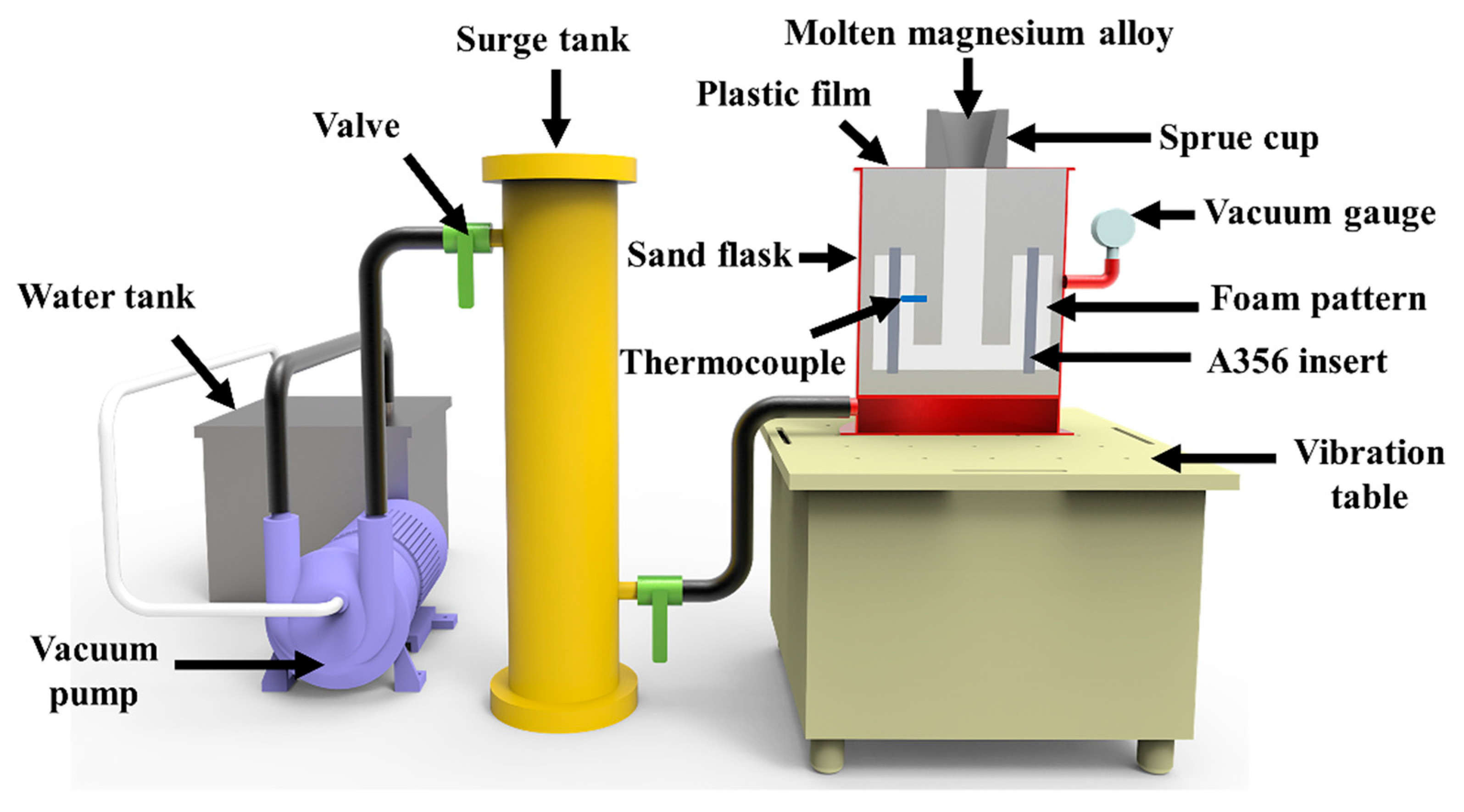
2.1. Materials and Fabrication Process

The commercial A356 aluminum alloy (Al-6.81Si-0.44Mg-0.21Fe-0.02Ti wt.%) and AZ91D magnesium alloy (Mg-9.08Al-0.62Zn-0.23Mn wt.%) were used to fabricate the Mg–Al bimetal. The aluminum rods with a diameter of 10 mm and a height of 110 mm were obtained from the commercial aluminum ingot by wire-electrode cutting. Figure 1a shows the original microstructures of the A356 rods. They were mainly composed of the Al substrate and the Si phase dispersed in the substrate. Figure 1b,c shows the microstructure zoom in areas b and c in Figure 1a, indicating that the original shape of the Si phase in the A356 rods is mostly needle-like or slate-like.
Before being used in the experiment, the as-cast A356 rods were polished with silicon carbide sandpapers, followed by cleaning with acid (50% HNO3 + 48% HF + 2% water) and lye (20 g/L NaOH, 5 g/L ZnO) to remove the oxide film on the surface. The treated A356 rods were assembled with the foam pattern. Then, the foam patterns were used for the LFCC process, of which the schematic diagram is illustrated in Figure 2. The foam pattern was placed in the sand flask, which was vibrated through the vibration table, while the loose sand was added to the sand flask. Under vibration, the loose sand in the sand flask was compacted. Then, a plastic film was placed over the surface of the loose sand. Finally, the vacuum pump was launched, and the sand flask was vacuumized and maintained at a vacuum of −0.03 MPa during the experiment. Under atmospheric pressure, the sand mold became tough and could tolerate the applied vibration. During the LFCC process, the pouring temperature of the AZ91D magnesium alloy was 720 °C. The 35 Hz vibration with different peak accelerations of 0.3 g (with the peak–peak displacement of 0.2 mm) and 0.9 g (with the peak–peak displacement of 0.6 mm) was applied to the manufacturing process of the Mg–Al bimetal by the vibration table under the sand flask, as shown in Figure 2, to investigate the effect of the vibration acceleration on the microstructure and bonding strength of the Mg–Al bimetal. During the casting process, the solidification temperature curve of the Mg–Al bimetal was measured at a sampling frequency of 75 Hz by the thermocouple, placed against the surface of the A356 insert, as shown in Figure 2.

2.2. Characterization

The Mg–Al bimetal specimens were cut along their cross section. A Quanta 200 scanning electron microscope (SEM, FEI, Eindhoven, The Netherlands) equipped with energy-dispersive X-ray spectroscopy (EDS) was used to investigate the microstructure and chemical composition of the Mg–Al bimetallic interface. The thickness of the Mg–Al interface and the size of the precipitated phase were measured using the image-pro software, and the measure method and process are illustrated in supplementary materials, as shown in Figures S1–S11. The element distribution of the interface was tested by WDS equipped with EPMA (EPMA-8050G (Shimadzu, Tokyo, Japan)). An XRD-6100 X-ray diffractometer (XRD, Shimadzu, Tokyo, Japan) was employed to identify the phase compositions at the Mg–Al interface. Further investigation of the constitutive phases at the interface was performed using transmission electron microscopy (TEM; JEOL2100, Tokyo, Japan). The bonding properties of the Mg–Al bimetal were tested by a push-out experiment in the ZwickZ100 universal testing machine (Zwick, Roell, Germany) with the compression rate of 0.5 mm/min. The schematic diagram of the push-out experiment is shown in Figure 3. The bonding property of the Mg–Al bimetal was evaluated according to Equation (1) [33,34,35]:
S = F / π d h ,
where S is the shear strength of the Mg–Al bimetal, F is the maximum force loaded obtained from the testing machine during the compression process, d is the diameter of the aluminum rod, and h is the height of the specimen. The fracture behavior of the Mg–Al bimetal was analyzed using SEM equipped with EDS.

3. Results

3.1. Effects of the Vibration Acceleration on Microstructure of the Mg–Al Bimetal

Figure 4a–c shows the interface morphology of the Mg–Al bimetal obtained with different conditions. Without the vibration, the outline of the interface is relatively flat. After applying the vibration, the thickness of the interface changes, and its morphology becomes irregular. When the vibration is not applied, there is a boundary in the Mg–Al interface at the location marked in Figure 4a. In the Mg–Al interface, many long dendrites grow towards the AZ91D matrix on the left side of the boundary, as shown in Figure 4a. On the right side of the boundary, the distribution of the grey precipitates in that area is not uniform. Near the A356 matrix, fewer precipitates can be observed.
When the vibration with 0.3 g is adopted, a clear boundary can still be observed in the Mg–Al interface at the location marked in Figure 4b, and there are obvious dendrites on the right side of it. However, the dendrites in the interface zone decrease compared with that without vibration. As the vibration acceleration increases to 0.9 g, no obvious boundary can be observed in the Mg–Al interface, and the dendrites in the Mg–Al interface decrease further. According to the above observations, three regions are selected for further observation to analyze the effect of vibration acceleration on the microstructure of the Mg–Al interface. Figure 4(a1–c3) shows the microstructures under high magnification in the regions marked in Figure 4a–c, respectively. EDS point analysis is used to analyze the composition of the phase existing in the Mg–Al interface, and the results of the corresponding points are shown in Table 1. The possible phases of the analyzed points are identified and indicated in Table 1, combing the EDS point analysis results with the Al–Mg [36] and Mg–Si [37] binary phase diagrams. According to these results, the Mg–Al interface can be divided into three regions: layer I (composed of Al3Mg2 and Mg2Si phases), layer II (composed of Al12Mg17, and Mg2Si phases), and layer III (Al12Mg17 + δ-Mg eutectic). Layers I and II can also be collectively called the IMCs layer because their substrates are the Al–Mg IMCs, and layer III can be named the eutectic layer. Layer I is mainly composed of the Mg2Si precipitates and Al3Mg2 substrate. There are many Mg2Si bulks and bars when the vibration is not applied, as shown in Figure 4(a1). After applying the vibration with the acceleration of 0.3 g, the Mg2Si phase is dispersed into granular form, as shown in Figure 4(b1). When the acceleration increases to 0.9 g, a large number of fine Mg2Si particles can be observed in the Al3Mg2 substrate, and the size of the Mg2Si phase is refined, as shown in Figure 4(c1).
Figure 4(a2–c2) shows the microstructures of the Mg–Al interfaces in layer II, which is composed of the black Mg2Si phase and the Al12Mg17 substrate. These results indicate that the vibration also affects the distribution and size of the Mg2Si phase in the Al12Mg17 substrate. Without applying the vibration, the aggregation of the Mg2Si phase is observed in Figure 5b. As shown in Figure 5b,c, fewer large Mg2Si bulks are observed in the Al12Mg17 substrate when the vibration is applied. It indicates that the Mg2Si phases in layer II are dispersed and refined after the mechanical vibration is brought to the manufacturing process. As to the microstructures in layer III, there is no significant difference in the δ-Mg and Al12Mg17 eutectic structure, after applying the vibration.
Figure 5 shows the distributions of the Si element in the Mg–Al bimetals prepared under different conditions. According to the microstructures observed in Figure 4, the Si elements distributed in the Mg–Al interface may mainly exist in the precipitates (the Mg2Si phase) located in the IMCs layer. After the vibration, the distribution of the Si element in the IMCs layer becomes more uniform, and the composition of the Si element in the eutectic layer increases slightly. It indicates that the vibration can improve the uniformity of the Mg2Si phase in the Mg–Al interface.
The above experimental results show that the Mg–Al interface can be divided into two parts, the IMCs layer (composed of layers I and II) and the eutectic layer (layer III). There are a lot of Mg2Si precipitates in the IMCs layer. In the eutectic layer, eutectic structures and some primary dendrites can be observed. These two parts can be distinguished and measured according to their differences in microstructure and contrast. Figure 6 summarizes the measurements of the thickness of the different parts of the Mg–Al interface. Compared with the Mg–Al bimetal without vibration, the thickness of region I decreases by 29.6%, from 914 μm to 643 μm, after applying the vibration of 0.9 g. However, the change of the thickness of the eutectic layer presents a different phenomenon. It decreases when the vibration is applied. Then, it increases when the acceleration of the vibration increases to about 0.9 g.
The microstructures shown in Figure 4 indicate that the Mg2Si phase mainly exists in layers I and II in the Mg–Al interface. To quantify the influence of vibration acceleration on the Mg2Si phase in the Mg–Al interface, we observed and measured the size of the Mg2Si phase in layers I and II, respectively, according to the locations shown in Figure 4a–c. Figure 7 shows the sizes of the Mg2Si phase in the Mg–Al interfaces. The results indicates that the size of the Mg2Si phase in layer II is larger than that in layer I. The size of the Mg2Si phase in the IMCs layer decreases with the enhancement of the acceleration of the vibration. Compared with the Mg–Al bimetal without vibration, the size of the Mg2Si phase decreases from 4.3 μm to 1.8 μm in layer I, and drops from 4.7 μm to 3.3 μm in layer II, after applying the vibration of 0.9 g. Figure 4 (a3–c3) shows the microstructures of layer III in the Mg–Al interfaces.
To further confirm the phase composition of the Mg–Al interface, the Mg–Al interface was observed by TEM. Figure 8a shows the bright-field image in layer I. There are many large granular phases distributed in the substrate. Figure 8c,d shows the analysis result of the diffraction spots. The results confirm that layer I in the Mg–Al interface is composed of the Al3Mg2 substrate and the Mg2Si precipitates. Research has shown the appearance of the bend contours is related to the strain field led by the residual stresses [38,39]. Since the linear expansion coefficient of Mg2Si (13 × 10−6 K−1) [40] is lower than that of the substrate (Al3Mg2, 22 × 10−6 K−1) [41], it will generate the compressive stress in the precipitates and the substrate. The stress may lead to the deformation of the substrate in the area near the Mg2Si phase. It may result in the occurrence of the bend contours, as shown in Figure 8a. On the other hand, the compressive stress in the Mg2Si phase may lead to a large number of dislocations in the particles, as shown in Figure 8b. These results indicate that the presence of Mg2Si in the interface may lead to the generation of residual stress in the interface. Therefore, the oversized Mg2Si phase may lead to the increase in residual stress and adversely affect the interface properties.

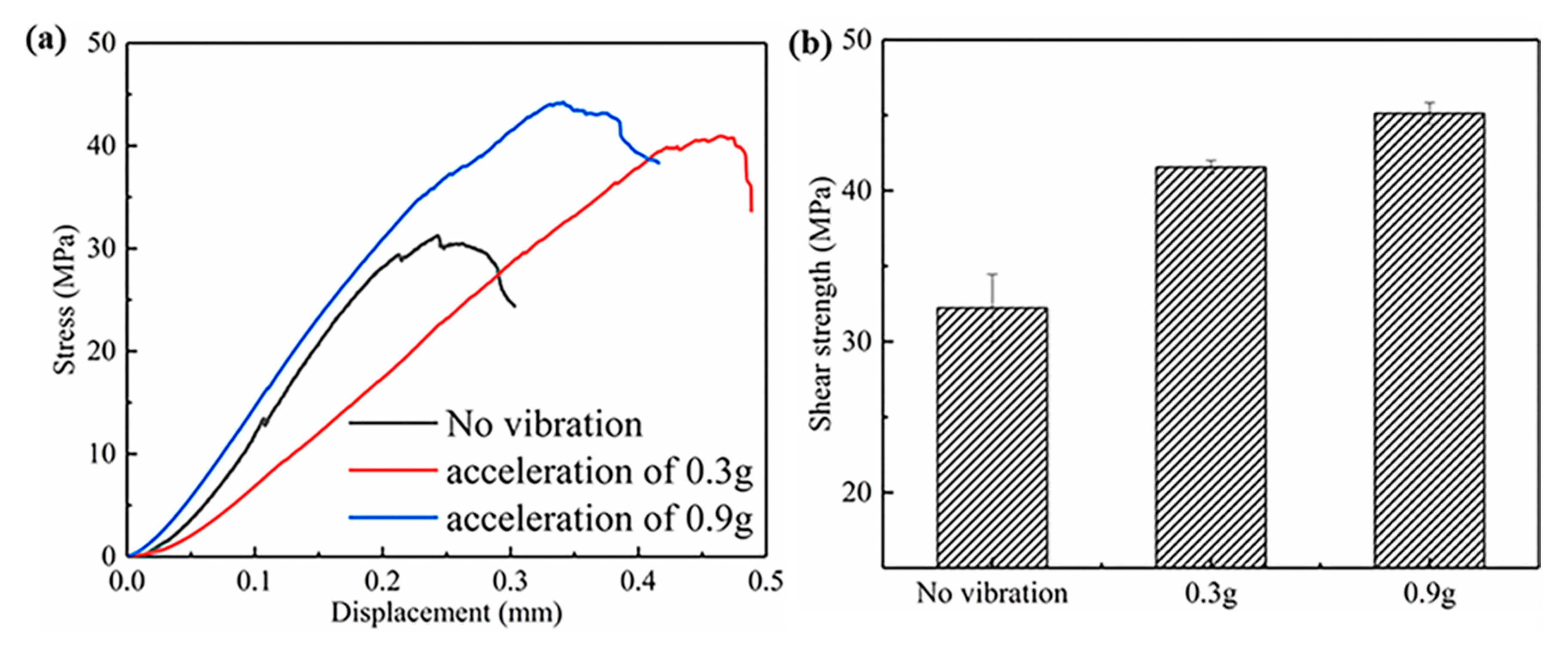
3.2. Effect of the Vibration Acceleration on Bonding Strength of the Mg–Al Bimetal

Figure 9a shows stress-displacement curves of the Mg–Al bimetals with different conditions, and the average shear strength of the Mg–Al bimetal prepared with different conditions is presented in Figure 9b. With the increase in the vibration acceleration, the shear strength of the Mg–Al bimetal gradually increases from 32.2 MPa to 41.5 MPa and 45.1 MPa. Compared with the Mg–Al bimetal obtained without vibration, it increases by 30% and 40%, respectively, after applying the vibration with the accelerations of 0.3 g and 0.9 g.
Figure 10 presents the SEM fractographies of the Mg–Al bimetals with different conditions, and the compositions of the phases observed on the fracture surface were analyzed. The cleavage planes and river patterns are observed in the SEM fractographies, as shown in Figure 10b,e,h, demonstrating that the Mg–Al bimetal fractures by a brittle fracture. Figure 10a shows the macroscopic morphology of the fracture surface of the Mg–Al bimetal without vibration. It indicates a noticeable slope on the surface of the fracture. Region b and c, shown in Figure 10a, were selected for observation. The results show that the Mg–Al bimetal fractures in different Mg–Al interface areas. In region b, shown in Figure 10b, the composition of the flat region is the Al3Mg2 phase, and the composition of the granular structure and pit area is the Mg2Si phase, indicating that region b belongs to the IMCs layer. The Mg2Si phase on the fracture surface aggregates and distributes in a reticular form when the vibration is not applied.
In region c of Figure 10a, the surface of the fracture is relatively straight and flat, and the Al12Mg17 + δ-Mg eutectic structure can be observed, indicating that it may belong to the eutectic layer. However, it is noteworthy that no plastic deformation is observed in the eutectic structure, as shown in Figure 10c. The fracture morphology of the Mg–Al bimetal with vibration demonstrates a similar fracture pattern. The Al3Mg2 phase, Mg2Si phase, and the eutectic structure are also found on the fracture surface. Compared with the fracture morphology of the Mg–Al bimetal without vibration, the aggregated Mg2Si phase is dispersed after applying the vibration, as shown in Figure 10e,h. Moreover, the δ-Mg in the eutectic structure is elongated, which is beneficial to improve the ductility of the Mg–Al interface.
After the shear testing, the fragments of broken interfacial structures were used for XRD testing. The fragments were broken and screened again before testing. The XRD testing result, shown in Figure 11, also confirms the presence of the Al3Mg2, Al12Mg17, and Mg2Si phases in the IMCs layers. Because the IMCs is more brittle, it is more likely to break and fall off during shear fracture. Due to the presence of a large number of δ-Mg phases in the eutectic structure, its plasticity is relatively better, and it is not easy for it to break and fall off, so it may not be included in the tested samples. This may explain the result that δ-Mg was not detected in the Figure 11.

4. Discussion

4.1. The Effect of Vibration Acceleration on the Microstructure of Mg–Al Bimetallic Interface

Figure 6 indicates that the thickness of the IMCs layer in the Mg–Al interface gradually decreases with the increase in the vibration acceleration. To investigate the influence mechanism of vibration acceleration on the thickness of the IMCs layer, the solidification curve of the interfacial region was measured by the thermocouple, located on the surface of the aluminum insert, and the results are shown in Figure 12. Previous research has shown that under the vibration, the disturbance and convection of the molten metal promoted the heat exchange at the solid–liquid interface [42]. As a result, it can increase the cooling rate during the solidification process. It can be observed that the cooling rate of the solidification process significantly increased after the application of the vibration, as shown in Figure 12a. According to the research of Haq et al. [43], the increase in the derivate curve indicates the generation of a new phase. Combining the Al–Mg binary phase diagram with the solidification curve shown in Figure 12, the reaction duration of the IMCs (both the Al3Mg2 and Al12Mg17) phases and the cooling rates during the formation of the IMCs were measured. Then, they are used to estimate the time taken to form the IMCs layer. The cooling rate during the formation of the IMCs was about 0.27 K/s, under the condition of no vibration. After applying the vibration with the accelerations of 0.3 g and 0.9 g, the cooling rates were 0.38 K/s and 0.40 K/s, respectively, during the formation of the IMCs. It increased significantly when the vibration was applied. Without vibration, the reaction duration of the IMCs layer (tIMCs) was about 47.7 s. After applying the vibration with the accelerations of 0.3 g and 0.9 g, it decreased to 34.5 s and 28.76 s, respectively. Compared with the Mg–Al bimetal obtained without vibration, it was reduced by 27.7% and 39.7%, respectively, after applying the vibration with the accelerations of 0.3 g and 0.9 g. The decrease in the tIMCs may be the reason why the thickness of the IMCs layer in the Mg–Al bimetallic interface decreased, with the increasing of the vibration acceleration.
Moreover, the disturbance and convection led by the vibration may also affect the size and distribution of the Mg2Si phase. Figure 13 shows the influence mechanism of the vibration on the size and distribution of the Mg2Si phase. The Si element in the Mg2Si phase comes from the Si phase in the A356 insert. Figure 13a shows the initial state of the Si element in the manufacturing process of the Mg–Al bimetal. In the beginning, the Si existed in the needle-like or slate-like Si phase on the aluminum substrate. After pouring the molten AZ91D alloys, the molten metal filled the position of the foam mold and came into contact with the A356 insert.
During the casting process, the highest temperature measured in the insert surface region was about 571 °C, as shown in Figure 12, close to the Al–Si eutectic reaction temperature of 577 °C [35]. The actual temperature of the insert surface area should be higher than the measured temperature, so when the AZ91D melt was in contact with the A356 matrix, the surface area of the insert might be melted. In addition, under the high-temperature condition, the mutual diffusion of the Al and Mg elements occurred between the solid aluminum insert and the molten magnesium alloy. It changed the composition of the insert surface, decreased the melting point of the insert surface [44], and promoted the melting of the surface region of the solid insert. So, the insert melted to form a molten pool on the surface of the solid insert, as shown in Figure 13b. In the molten pool, there were some Si-rich regions where the eutectic Si phase initially existed. Subsequently, the Si element in the molten pool gradually diffused due to the concentration gradient, as shown in Figure 13c. Without vibration, the diffusion distance of the Si element was relatively short due to the brief solidification time of the interface region during the manufacturing process. Finally, as shown in Figure 13c, the Si element aggregated in a small area and precipitated the large Mg2Si bulks from the molten metal, as shown in Figure 13d.
After applying the vibration, the disturbance and convection led by the vibration promoted the diffusion of the Si element. The diffusion distance of the Si element increased, and the Si element was dispersed into a larger region, as shown in Figure 13e. Finally, the size of the Mg2Si phase was refined, and its distribution became more uniform, as shown in Figure 13f. Therefore, it can be seen from the above experiment results that the size of the Mg2Si phase in the IMCs layer is gradually refined as the vibration acceleration increases to 0.9 g.
However, the improvement of the distribution of the Mg2Si phase in layer I is mainly observed after applying the vibration. Since the A356 insert melts from the outside to the inside during the preparation process, the Si element in layer II has more diffusion time. As a result, the distribution of the Mg2Si phase in that region is relatively uniform. Therefore, the effect of the vibration on the distribution of the Mg2Si phase in layer II is not as significant as that of layer I.

4.2. Strengthening Mechanism of the Mg–Al Bimetal

The IMCs layer in the Mg–Al interface is mainly composed of the IMCs substrate and the Mg2Si phase distributed on the substrate. Compared with A356 and AZ91D matrixes, the IMCs layer has significantly higher hardness and lower plastic deformation ability [45]. Therefore, the thickness of the IMCs layer has an important influence on the number of brittle phases and bonding properties of the Mg–Al bimetal. In the preparation process of the Mg–Al bimetal, reducing the content of these brittle phases is the key to improving the bonding property of the Mg–Al bimetal [46,47]. After applying the vibration, the thinning of the IMCs layer means decreasing the mass of the brittle phases, thereby improving the mechanical properties of the Mg–Al bimetal. Studies have shown that the size and morphology of the Mg2Si phase have an important effect on the properties of the material [48,49]. The refined Mg2Si phase may also contribute to enhancing the shear strength of the Mg–Al bimetal. Without vibration, there are many Mg2Si bulks in the IMCs layer. Since the linear expansion coefficient of the Mg2Si is lower than that of the Al3Mg2 substrate, it will generate compressive stress in the Mg2Si precipitates. Existing research has found that for the large-sized Mg2Si phase, its ability to carry external loads is weaker because the larger size reinforcement particles are more likely to fracture under the action of the residual stress [50]. Therefore, under the action of the stress, the Mg2Si bulks in the IMCs layer are more likely to form cracks when it is under load, leading to the formation of crack propagation channels, which will adversely affect the ability of the Mg2Si phase to withstand and disperse loads [51]. When the vibration is applied, the thickness of the IMCs layer decreases, and the Mg2Si phase is refined. Therefore, the shear strength of the Mg–Al bimetal is improved from 32.2 MPa to 41.5 MPa, after applying the vibration with the acceleration of 0.3 g. As the acceleration increases to 0.9 g, the shear strength of the Mg–Al bimetal continues to rise to 45.1 MPa, due to the further reduction in the thickness of the IMCs layer and the further refinement of the Mg2Si phase.

5. Conclusions

In the present work, the Mg–Al bimetal was fabricated by the LFCC process, and the effect of the vibration acceleration on the interfacial microstructure and mechanical properties was studied. The main conclusions are presented in the following:
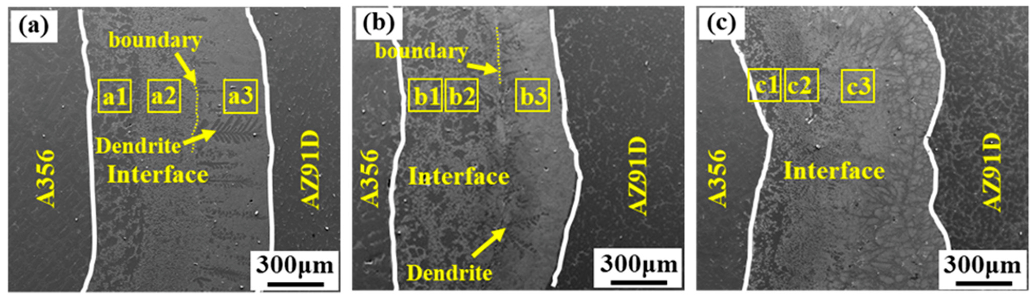
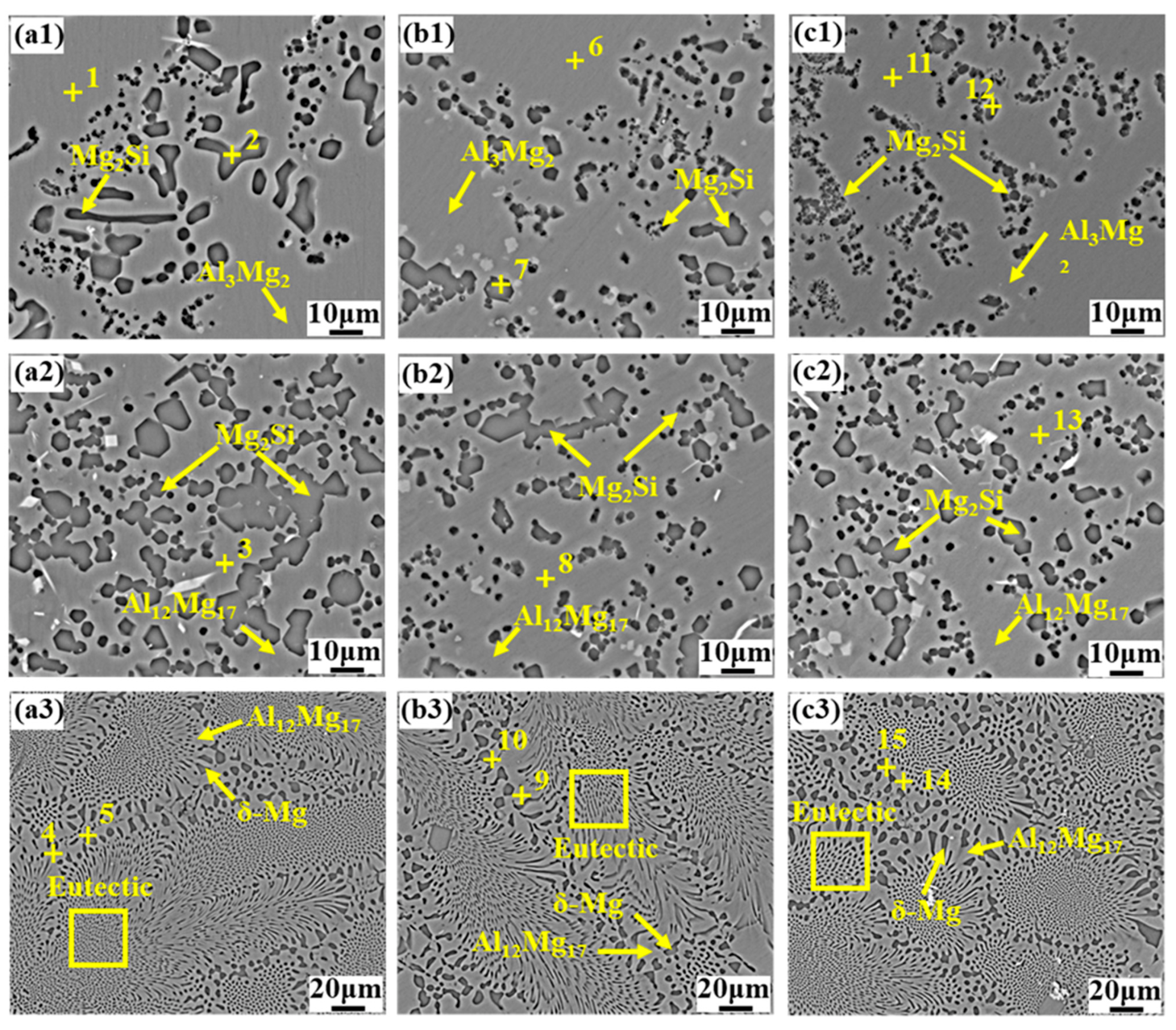
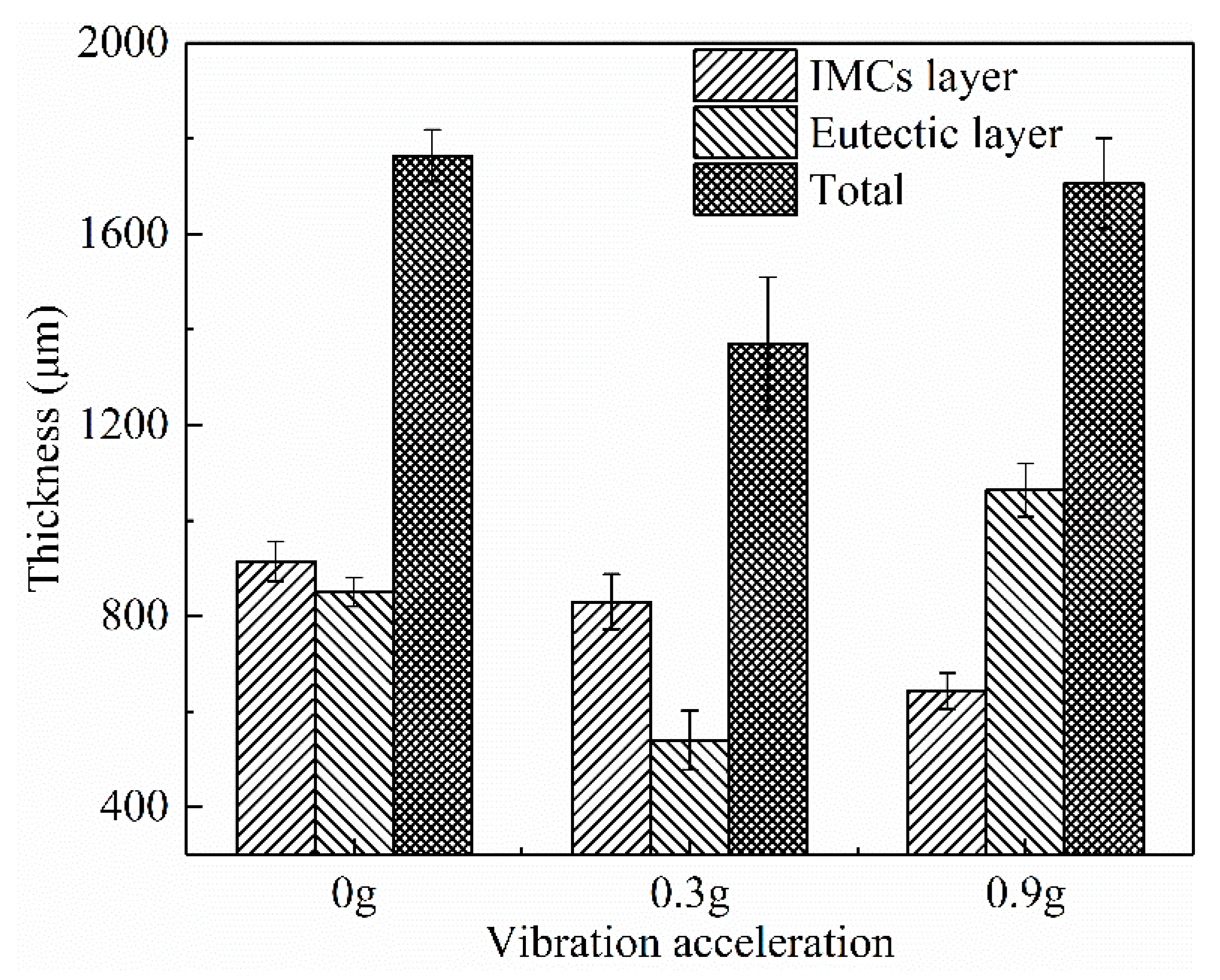
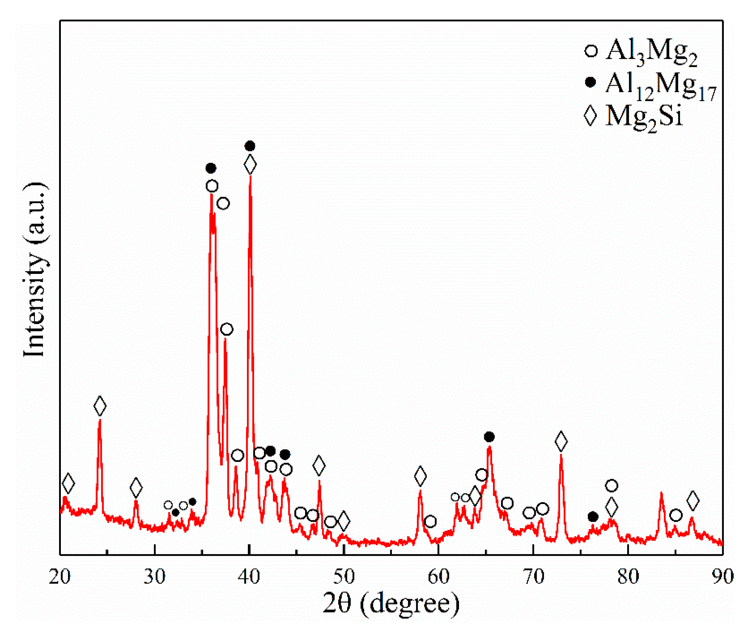
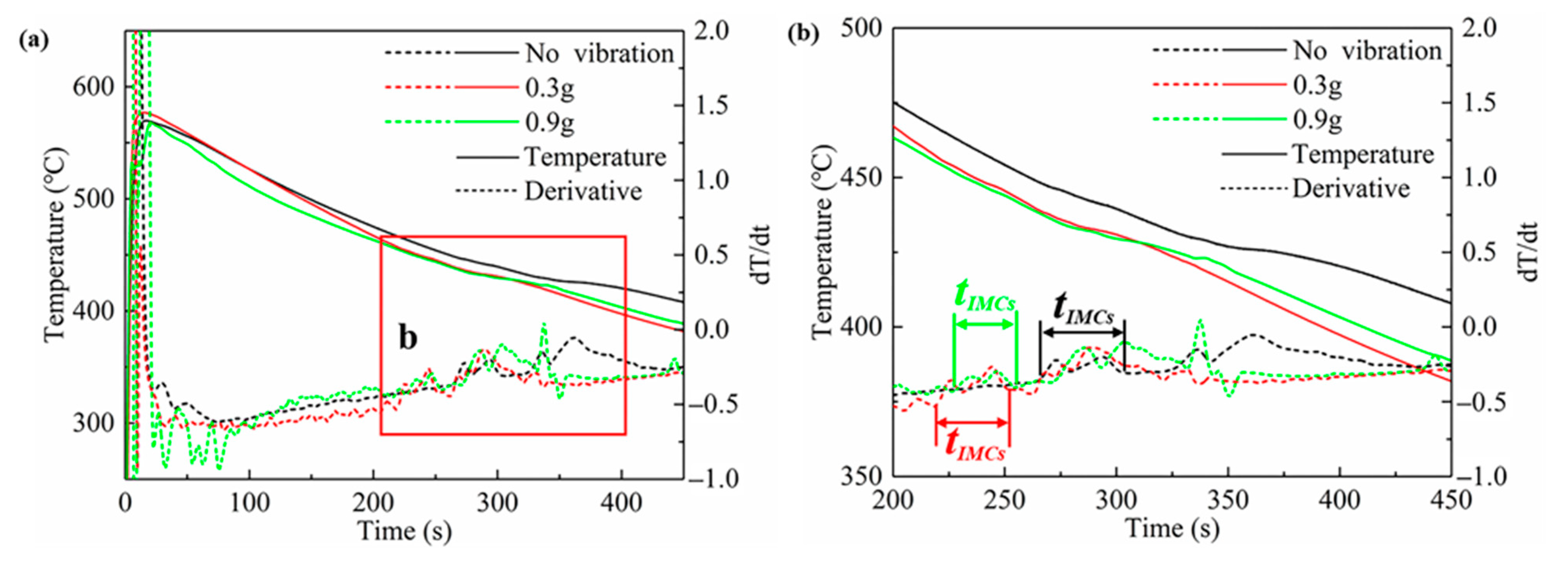
  • The interface of the Mg–Al bimetal fabricated by the LFCC process was divided into three areas, named layer I (Al3Mg2 and Mg2Si phases), layer II (Al12Mg17, and Mg2Si phases), and layer III (Al12Mg17 + δ-Mg eutectic structure). With the increase in the vibration acceleration, the cooling rate of the Mg–Al bimetal increased, and the reaction duration of the IMCs layer (including layers I and II) decreased. In addition, the thickness of the IMCs reduced.
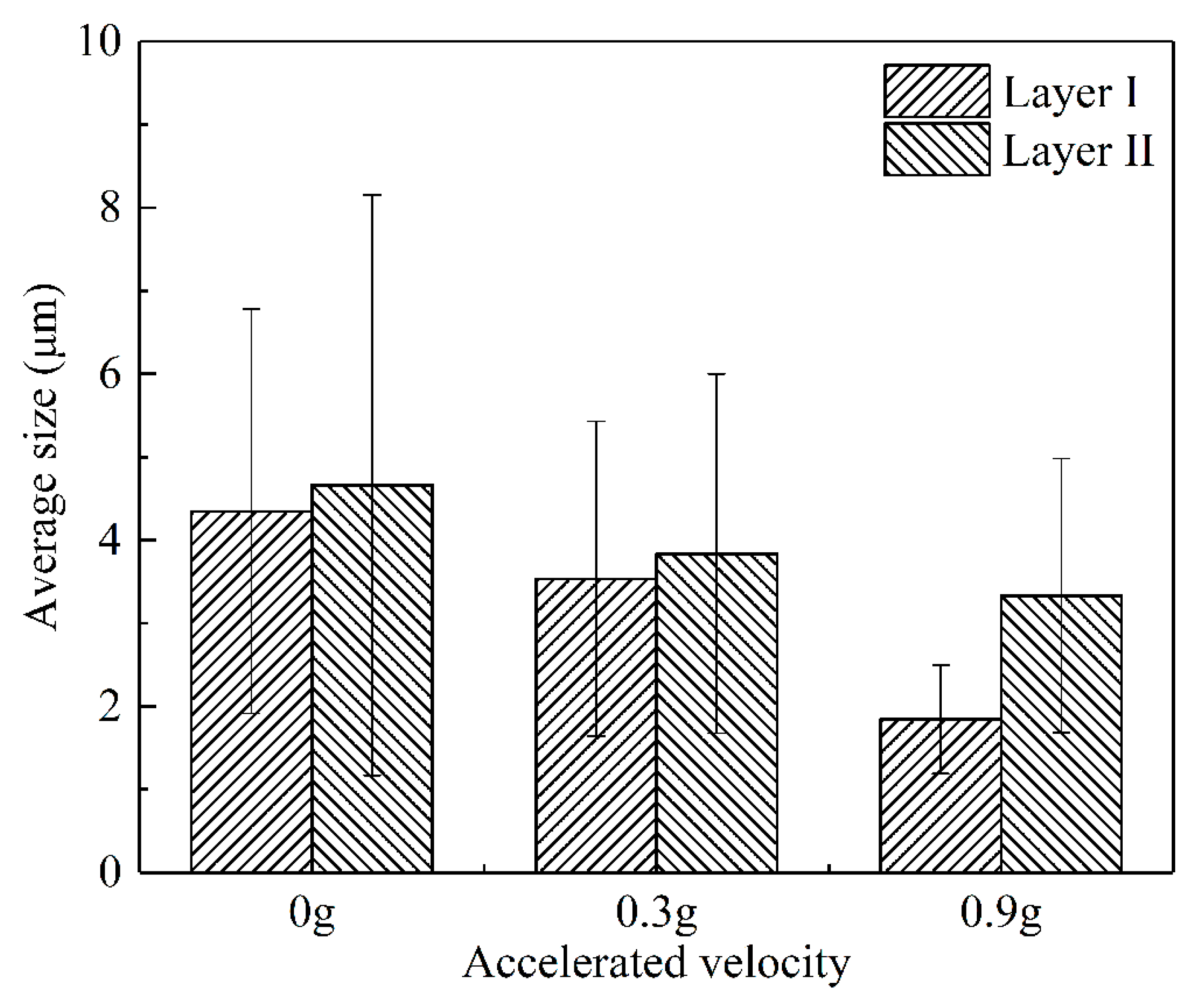
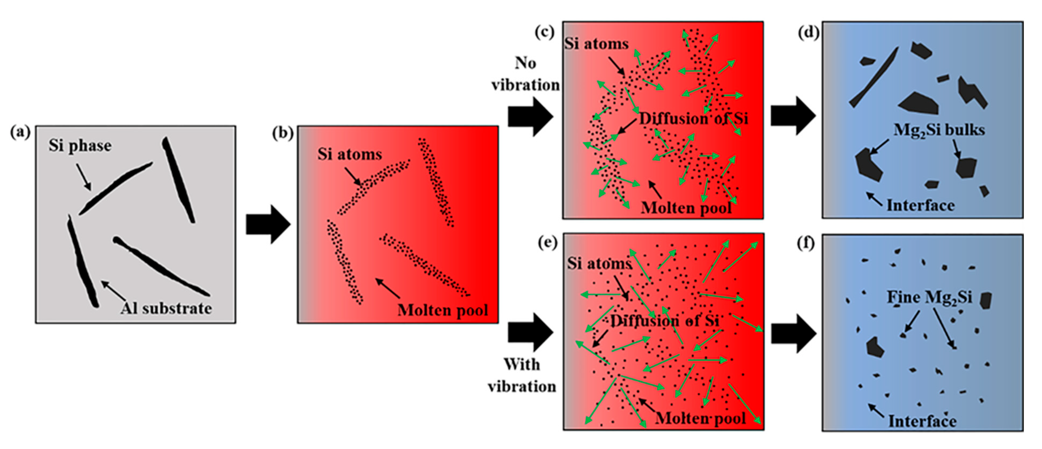
  • The vibration promoted the refinement and dispersion of the Mg2Si phase. After applying the vibration, the distribution of the Mg2Si in the IMCs layer became more uniform, and the size of the Mg2Si phase decreased with the increase in the vibration acceleration.
  • The shear strength of the Mg–Al bimetal increased with the increase in the vibration acceleration. As the acceleration grew to 0.9 g, the shear strength of the Mg–Al bimetal continued to rise to 45.1 MPa, which was 40% higher than that of the Mg–Al bimetal without vibration. The significant improvement of the shear strength of the Mg–Al bimetal might be attributed to the decrease in the IMC’s thickness, as well as the refinement and uniform distribution of the Mg2Si phase.

Supplementary Materials

The following supporting information can be downloaded at: https://www.mdpi.com/article/10.3390/met12050766/s1, Figure S1: The original SEM image., Figure S2: The standard for the measurement., Figure S3: The processed image used for measurement., Figure S4: Space calibration, Figure S5: Select the area to be measured., Figure S6: Using the “perform segmentation” function to convert images to black and white image., Figure S7: The black and white image, Figure S8: Click on the “Count and measure objects” option, Figure S9: Click on the “Select Measurements” option., Figure S10: Setup the measurement options., Figure S11: Measurement results.

Author Contributions

Conceptualization, J.W. and G.L.; methodology, Z.Z.; investigation, F.G. and J.W.; writing—original draft preparation, F.G.; writing—review and editing, W.J. and S.F.; visualization, S.F.; Supervision, W.J. All authors have read and agreed to the published version of the manuscript.

Funding

This research was funded by National Natural Science Foundation of China [grant number 52075198], National Key Research and Development Program of China [grant number 2020YFB2008304] and State Key Lab of Advanced Metals and Materials [grant number 2021-ZD07].

Data Availability Statement

Data presented in this article are available at request from the corresponding author.

Acknowledgments

The authors gratefully acknowledge the support provided by the Analytical and Testing Center, HUST.

Conflicts of Interest

The authors declare no conflict of interest.

References

  1. Yu, H.M.; Li, W.; Tan, Y.; Tan, Y.B. The Effect of Annealing on the Microstructure and Properties of Ultralow-Temperature Rolled Mg–2Y–0.6Nd–0.6Zr Alloy. Metals 2021, 11, 315. [Google Scholar] [CrossRef]
  2. Yang, X.K.; Xiong, B.Q.; Li, X.W.; Yan, L.Z.; Li, Z.H.; Zhang, Y.A.; Li, Y.N.; Wen, K.; Liu, H.W. Effect of Li addition on mechanical properties and ageing precipitation behavior of extruded Al−3.0Mg−0.5Si alloy. J. Cent. South Univ. 2021, 28, 2636–2646. [Google Scholar] [CrossRef]
  3. Li, Z.C.; Deng, Y.L.; Yuan, M.F.; Zhang, J.; Guo, X.B. Effect of isothermal compression and subsequent heat treatment on grain structures evolution of Al-Mg-Si alloy. J. Cent. South Univ. 2021, 28, 2670–2686. [Google Scholar] [CrossRef]
  4. Zhang, D.D.; Liu, C.M.; Wan, Y.C.; Jiang, S.N.; Zeng, G. Microstructure and anisotropy of mechanical properties in ring rolled AZ80-Ag alloy. J. Cent. South Univ. 2021, 28, 1316–1323. [Google Scholar] [CrossRef]
  5. Suhuddin, U.F.H.; Fischer, V.; dos Santos, J.F. The Thermal Cycle during the Dissimilar Friction Spot Welding of Aluminum and Magnesium Alloy. Scr. Mater. 2013, 68, 87–90. [Google Scholar] [CrossRef] [Green Version]
  6. Li, G.; Jiang, W.; Guan, F.; Zhu, J.; Zhang, Z.; Fan, Z. Microstructure, Mechanical Properties and Corrosion Resistance of A356 Aluminum/AZ91D Magnesium Bimetal Prepared by a Compound Casting Combined with a Novel Ni-Cu Composite Interlayer. J. Mater. Process. Technol. 2021, 288, 116874. [Google Scholar] [CrossRef]
  7. Xu, Z.; Li, Z.; Li, J.; Ma, Z.; Yan, J. Control Al/Mg Intermetallic Compound Formation during Ultrasonic-Assisted Soldering Mg to Al. Ultrason. Sonochem. 2018, 46, 79–88. [Google Scholar] [CrossRef] [Green Version]
  8. Feng, B.; Xin, Y.; Guo, F.; Yu, H.; Wu, Y.; Liu, Q. Compressive Mechanical Behavior of Al/Mg Composite Rods with Different Types of Al Sleeve. Acta Mater. 2016, 120, 379–390. [Google Scholar] [CrossRef]
  9. Zhu, Z.; Shi, R.; Klarner, A.D.; Luo, A.A.; Chen, Y. Predicting and Controlling Interfacial Microstructure of Magnesium/Aluminum Bimetallic Structures for Improved Interfacial Bonding. J. Magnes. Alloys 2020, 8, 578–586. [Google Scholar] [CrossRef]
  10. He, K.; Zhao, J.; Li, P.; He, J.; Tang, Q. Investigation on Microstructures and Properties of Arc-Sprayed-Al/AZ91D Bimetallic Material by Solid–Liquid Compound Casting. Mater. Des. 2016, 112, 553–564. [Google Scholar] [CrossRef]
  11. Hajjari, E.; Divandari, M.; Razavi, S.H.; Emami, S.M.; Homma, T.; Kamado, S. Dissimilar Joining of Al/Mg Light Metals by Compound Casting Process. J. Mater. Sci. 2011, 46, 6491–6499. [Google Scholar] [CrossRef]
  12. Emami, S.M.; Divandari, M.; Hajjari, E.; Arabi, H. Comparison between Conventional and Lost Foam Compound Casting of Al/Mg Light Metals. Int. J. Cast Met. Res. 2013, 26, 43–50. [Google Scholar] [CrossRef]
  13. Jiang, W.; Fan, Z.; Li, G.; Yang, L.; Liu, X. Effects of Melt-to-Solid Insert Volume Ratio on the Microstructures and Mechanical Properties of Al/Mg Bimetallic Castings Produced by Lost Foam Casting. Metall. Mater. Trans. A 2016, 47, 6487–6497. [Google Scholar] [CrossRef]
  14. Jiang, W.; Li, G.; Fan, Z.; Wang, L.; Liu, F. Investigation on the Interface Characteristics of Al/Mg Bimetallic Castings Processed by Lost Foam Casting. Metall. Mater. Trans. A 2016, 47, 2462–2470. [Google Scholar] [CrossRef]
  15. Fan, S.; Jiang, W.; Li, G.; Mo, J.; Fan, Z. Fabrication and Microstructure Evolution of Al/Mg Bimetal Using a near-Net Forming Process. Mater. Manuf. Processes 2017, 32, 1391–1397. [Google Scholar] [CrossRef]
  16. Li, G.; Yang, W.; Jiang, W.; Guan, F.; Jiang, H.; Wu, Y.; Fan, Z. The Role of Vacuum Degree in the Bonding of Al/Mg Bimetal Prepared by a Compound Casting Process. J. Mater. Process. Technol. 2019, 265, 112–121. [Google Scholar] [CrossRef]
  17. Abdollahzadeh, A.; Shokuhfar, A.; Cabrera, J.M.; Zhilyaev, A.P.; Omidvar, H. The Effect of Changing Chemical Composition on Dissimilar Mg/Al Friction Stir Welded Butt Joints Using Zinc Interlayer. J. Manuf. Processes 2018, 34, 18–30. [Google Scholar] [CrossRef] [Green Version]
  18. Zhang, J.; Luo, G.; Wang, Y.; Xiao, Y.; Shen, Q.; Zhang, L. Effect of Al Thin Film and Ni Foil Interlayer on Diffusion Bonded Mg–Al Dissimilar Joints. J. Alloys Compd. 2013, 556, 139–142. [Google Scholar] [CrossRef]
  19. Wang, Y.; Prangnell, P.B. Evaluation of Zn-Rich Coatings for IMC Reaction Control in Aluminum-Magnesium Dissimilar Welds. Mater. Charact. 2018, 139, 100–110. [Google Scholar] [CrossRef] [Green Version]
  20. Xu, Z.; Li, Z.; Zhao, D.; Liu, X.; Yan, J. Effects of Zn on Intermetallic Compounds and Strength of Al/Mg Joints Ultrasonically Soldered in Air. J. Mater. Process. Technol. 2019, 271, 384–393. [Google Scholar] [CrossRef]
  21. Mola, R.; Bucki, T.; Gwoździk, M. The Effect of a Zinc Interlayer on the Microstructure and Mechanical Properties of a Magnesium Alloy (AZ31)–Aluminum Alloy (6060) Joint Produced by Liquid–Solid Compound Casting. JOM 2019, 71, 2078–2086. [Google Scholar] [CrossRef] [Green Version]
  22. Liu, N.; Liu, C.; Liang, C.; Zhang, Y. Influence of Ni Interlayer on Microstructure and Mechanical Properties of Mg/Al Bimetallic Castings. Met. Mater. Trans. A 2018, 49, 3556–3564. [Google Scholar] [CrossRef]
  23. Xu, G.; Chen, Y.; Liu, L.; Luo, A.; Ma, L. Effect of La on Structures and Properties of the Liquid-Solid Diffusion Bonding Interface of Magnesium/Aluminum. Chin. J. Nonferrous Met. 2014, 24, 2743–2748. [Google Scholar]
  24. Wu, L.; Kang, H.; Chen, Z.; Liu, N.; Wang, T. Horizontal Continuous Casting Process under Electromagnetic Field for Preparing AA3003/AA4045 Clad Composite Hollow Billets. Trans. Nonferrous Met. Soc. China 2015, 25, 2675–2685. [Google Scholar] [CrossRef]
  25. Tayal, R.K.; Kumar, S.; Singh, V. Experimental Investigation and Optimization of Process Parameters for Shear Strength of Compound Cast Bimetallic Joints. Trans. Indian Inst. Met. 2018, 71, 2173–2183. [Google Scholar] [CrossRef]
  26. Tayal, R.K.; Kumar, S.; Singh, V.; Gupta, A.; Ujjawal, D. Experimental Investigation and Evaluation of Joint Strength of A356/Mg Bimetallic Fabricated Using Compound Casting Process. Int. Metalcast. 2019, 13, 686–699. [Google Scholar] [CrossRef]
  27. Babaee, M.H.; Maleki, A.; Niroumand, B. A Novel Method to Improve Interfacial Bonding of Compound Squeeze Cast Al/Al−Cu Macrocomposite Bimetals: Simulation and Experimental Studies. Trans. Nonferrous Met. Soc. China 2019, 29, 1184–1199. [Google Scholar] [CrossRef]
  28. Wang, C.; Cui, J. Application and Research of Vibration Technology in Metal Casting Process. Foundry Technol. 2018, 39, 2240–2243. [Google Scholar]
  29. Yuanyang, L.I.; Chen, W.; Zheng, K.; Wang, J.; Zheng, Z. Effect of Mechanical Vibration on Bimetallic Compound Casting Behavior. Foundry Technol. 2017, 38, 377–381. [Google Scholar]
  30. Zhao, J.; Shang, Z.; Wang, L.; Hou, Z.; Wang, Z. Effect of Mechanical Vibration on Heat Transfer of Casting-Mold Interface in Filling and Solidification Process of AZ91 Magnesium Alloy. Rare Met. Mater. Eng. 2015, 44, 3141–3146. [Google Scholar]
  31. Promakhov, V.; Khmeleva, M.; Zhukov, I.; Platov, V.; Khrustalyov, A.; Vorozhtsov, A. Influence of Vibration Treatment and Modification of A356 Aluminum Alloy on Its Structure and Mechanical Properties. Metals 2019, 9, 87. [Google Scholar] [CrossRef] [Green Version]
  32. Meng, X.; Jin, Y.; Ji, S.; Yan, D. Improving Friction Stir Weldability of Al/Mg Alloys via Ultrasonically Diminishing Pin Adhesion. J. Mater. Sci. Technol. 2018, 34, 1817–1822. [Google Scholar] [CrossRef]
  33. Li, G.; Jiang, W.; Guan, F.; Zhu, J.; Yu, Y.; Fan, Z. Improving mechanical properties of AZ91D magnesium/A356 aluminum bimetal prepared by compound casting via a high velocity oxygen fuel sprayed Ni coating. J. Magnes. Alloys 2021, in press. [Google Scholar] [CrossRef]
  34. Wen, F.; Zhao, J.; Yuan, M.; Wang, J.; Zheng, D.; Zhang, J.; He, K.; Shangguan, J.; Guo, Y. Influence of Ni interlayer on interfacial microstructure and mechanical properties of Ti-6Al-4V/AZ91D bimetals fabricated by a solid–liquid compound casting process. J. Magnes. Alloys 2021, 9, 1382–1395. [Google Scholar] [CrossRef]
  35. Feng, B.; Feng, X.; Yan, C.; Xin, Y.; Wang, H.; Wang, J.; Zheng, K. On the rule of mixtures for bimetal composites without bonding. J. Magnes. Alloys 2020, 8, 1253–1261. [Google Scholar] [CrossRef]
  36. Jia, B.R.; Liu, L.B.; Yi, D.Q.; Jin, Z.P.; Nie, J.F. Thermodynamic Assessment of the Al–Mg–Sm System. J. Alloys Compd. 2008, 459, 267–273. [Google Scholar] [CrossRef]
  37. Yan, X.-Y.; Chang, Y.A.; Zhang, F. A Thermodynamic Analysis of the Mg-Si System. J. Phase Equilibria 2000, 21, 379. [Google Scholar] [CrossRef]
  38. Zhao, X.; Bhushan, B. Material Removal Mechanisms of Single-Crystal Silicon on Nanoscale and at Ultralow Loads. Wear 1998, 223, 66–78. [Google Scholar] [CrossRef]
  39. Rodríguez-González, B.; Pastoriza-Santos, I.; Liz-Marzán, L.M. Bending Contours in Silver Nanoprisms. J. Phys. Chem. B 2006, 110, 11796–11799. [Google Scholar] [CrossRef]
  40. Imai, M.; Isoda, Y.; Udono, H. Thermal Expansion of Semiconducting Silicides β-FeSi2 and Mg2Si. Intermetallics 2015, 67, 75–80. [Google Scholar] [CrossRef]
  41. Trebin, H.-R. Quasicrystals: Structure and Physical Properties; John Wiley & Sons: Hoboken, NJ, USA, 2003; ISBN 3-527-40399-X. [Google Scholar]
  42. Lyubimova, T.P.; Parshakova, Y.N. Effect of Rotational Vibrations on Directional Solidification of High-Temperature Binary SiGe Alloys. Int. J. Heat Mass Transf. 2018, 120, 714–723. [Google Scholar] [CrossRef]
  43. Ihsan-ul-haq; Shin, J.-S.; Lee, Z.-H. Computer-Aided Cooling Curve Analysis of A356 Aluminum Alloy. Met. Mater. Int. 2004, 10, 89–96. [Google Scholar] [CrossRef]
  44. Xiao, Y.; Ji, H.; Li, M.; Kim, J. Ultrasound-Induced Equiaxial Flower-like CuZn5/Al Composite Microstructure Formation in Al/Zn–Al/Cu Joint. Mater. Sci. Eng. A 2014, 594, 135–139. [Google Scholar] [CrossRef]
  45. Li, G.; Jiang, W.; Guan, F.; Zhu, J.; Jiang, H.; Fan, Z. Effect of Insert Materials on Microstructure and Mechanical Properties of Al/Mg Bimetal Produced by a Novel Solid-Liquid Compound Process. J. Manuf. Process. 2019, 47, 62–73. [Google Scholar] [CrossRef]
  46. Chen, Y.; Zhang, H.; Zhu, Z.; Xu, G.; Luo, A.A.; Liu, L. Inhibiting Brittle Intermetallic Layer in Magnesium/Aluminum Bimetallic Castings via In Situ Formation of Mg2Si Phase. Met. Mater. Trans. B 2019, 50, 1547–1552. [Google Scholar] [CrossRef]
  47. Zamani, R.; Mirzadeh, H.; Emamy, M. Mechanical Properties of a Hot Deformed Al-Mg2Si in-Situ Composite. Mater. Sci. Eng. A 2018, 726, 10–17. [Google Scholar] [CrossRef]
  48. Maleki, M.; Mirzadeh, H.; Emamy, M. Improvement of Mechanical Properties of in Situ Mg-Si Composites via Cu Addition and Hot Working. J. Alloy Compd. 2022, 905, 164176. [Google Scholar] [CrossRef]
  49. Guo, Y.; Quan, G.; Ren, L.; Liu, B.; Al-Ezzi, S.; Pan, H. Effect of Zn Interlayer Thickness on the Microstructure and Mechanical Properties of Two-Step Diffusion Bonded Joint of ZK60Mg and 5083Al. Vacuum 2019, 161, 353–360. [Google Scholar] [CrossRef]
  50. Lloyd, D.J. Aspects of Fracture in Particulate Reinforced Metal Matrix Composites. Acta Met. Mater. 1991, 39, 59–71. [Google Scholar] [CrossRef]
  51. Wang, Z.; Song, M.; Sun, C.; He, Y. Effects of Particle Size and Distribution on the Mechanical Properties of SiC Reinforced Al–Cu Alloy Composites. Mater. Sci. Eng. A 2011, 528, 1131–1137. [Google Scholar] [CrossRef]
Figure 1. (a) Original microstructures of the A356 insert; (b) microstructures zoom in area b in (a); (c) microstructures zoom in area c in (a).
Metals 12 00766 g001
Figure 2. The schematic diagram of the experiment.
Metals 12 00766 g002
Figure 3. Schematic diagram of the push-out test for the shear strength testing.
Metals 12 00766 g003
Figure 4. Microstructures of the Mg–Al bimetals obtained with different conditions: (a) without vibration; (b) with the vibration acceleration of 0.3 g; (c) with the vibration acceleration of 0.9 g; (a1a3) microstructures under high magnification in the regions a1–a3 in (a), respectively; (b1b3) microstructures under high magnification in the regions b1–b3 in (b), respectively; (c1c3) microstructures under high magnification in the regions c1–c3 in (c), respectively.
Metals 12 00766 g004aMetals 12 00766 g004b
Figure 5. The distributions of the Si element in the Mg–Al bimetals prepared with different conditions: (a) without vibration; (b) with the vibration acceleration of 0.3 g; (c) applying the vibration acceleration of 0.9 g.
Metals 12 00766 g005
Figure 6. The thicknesses of the Mg–Al interfaces obtained with different conditions.
Metals 12 00766 g006
Figure 7. The sizes of the Mg2Si phase in the IMCs layers of the Mg–Al interfaces.
Metals 12 00766 g007
Figure 8. TEM analysis results of layer I in the Mg–Al interface: (a,b) TEM bright-field images; (c) SAED pattern of the Al3Mg2 phase; (d) SAED pattern of the Mg2Si phase.
Metals 12 00766 g008aMetals 12 00766 g008b
Figure 9. (a) Stress-displacement curves of the Mg–Al bimetals with different conditions; (b) Shear strengths of Mg–Al bimetals with different conditions.
Metals 12 00766 g009
Figure 10. SEM morphologies of the fracture surfaces of the Mg–Al bimetals at the Mg substrate side: (a) macroscopic morphology of the fracture surface of the Mg–Al bimetal without vibration; (b,c) enlarged images of region b and c in (a), respectively; (d) macroscopic morphology of the fracture surface of the Mg–Al bimetal with the vibration acceleration of 0.3 g; (e,f) enlarged images of region e and f in (d), respectively; (g) macroscopic morphology of the fracture surface of the Mg–Al bimetal with the vibration acceleration of 0.9 g; and (h,i) enlarged images of region h and i in (g), respectively.
Metals 12 00766 g010
Figure 11. XRD diagram of the IMCs layer of the Mg–Al interface.
Metals 12 00766 g011
Figure 12. (a) Results of thermocouple measurement; (b) Temperature curve zoom in area b in (a).
Metals 12 00766 g012
Figure 13. The influence mechanism of the vibration on the size and distribution of the Mg2Si phase: (a) The initial state of the Si element; (b) The insert melted to form a molten pool on the surface of the solid insert; (c) The diffusion of the Si in the molten pool under the condition of no vibration; (d) The interface formed under the condition of no vibration; (e) The diffusion of the Si in the molten pool after applying the vibration; (f) The interface formed after applying the vibration.
Metals 12 00766 g013
Table 1. Results of EDS analysis at different locations in Figure 4.
Area No.Element Compositions (At.%)Possible Phase
MgAlSi
138.7361.27-Al3Mg2
258.0212.5629.43Mg2Si
350.8249.18-Al12Mg17
463.9436.06-Al12Mg17
583.6616.34-δ-Mg
638.7361.27-Al3Mg2
761.2314.8423.93Mg2Si
849.4550.55-Al12Mg17
965.6534.35-Al12Mg17
1077.7022.30-δ-Mg
1138.7461.26-Al3Mg2
1261.8722.0916.03Mg2Si
1349.2850.72-Al12Mg17
1463.4336.57-Al12Mg17
1585.7814.22-δ-Mg
Publisher’s Note: MDPI stays neutral with regard to jurisdictional claims in published maps and institutional affiliations.

