Article

Direct Observation of Cu Clusters and Dislocation Loops by Cs-Corrected STEM in Fe-0.6wt%Cu Alloy Irradiated in BR2

1
Research Institute for Applied Mechanics, Kyushu University, 6-1, Kasuga-kouenn, Kasugashi 816-8580, Fukuoka, Japan
2
Interdisciplinary Graduate School of Engineering Sciences, Kyushu University, 6-1, Kasuga-kouenn, Kasugashi 816-8580, Fukuoka, Japan
3
Faculty of Science and Engineering, Graduated School of Engineering, Iwate University, 4-3-5, Ueda, Morioka 020-8551, Iwate, Japan
*
Author to whom correspondence should be addressed.
Metals 2022, 12(5), 729; https://doi.org/10.3390/met12050729
Submission received: 25 February 2022 / Revised: 11 April 2022 / Accepted: 20 April 2022 / Published: 25 April 2022
(This article belongs to the Special Issue Radiation Damage in Metals and Alloys)

Abstract

:
The neutron irradiation of Fe-based fusion and fission reactor materials leads to an increase in ductile-to-brittle transition temperature with a decrease in upper shelf energy. It is well known that Cu content has a strong influence on the embrittlement phenomenon, as Cu-rich clusters (CRPs) are thought to be directly responsible for embrittlement. In contrast, mechanical property studies for steels with different Cu levels exhibit dominant matrix defects in the embrittlement of both low-Cu steels and high-Cu steels at high fluences. To determine the effects of dislocation loops and CRPs on radiation hardening in those steels, neutron irradiation was conducted on Fe-0.6wt%Cu alloy. The neutron irradiation was performed in BR2 at 290 °C up to a dose of 4.1 × 1024 n/m2. After irradiation, the microstructure was observed and analyzed by spherical aberration-corrected transmission electron microscopy (TEM) and scanning transmission electron microscopy (STEM) combined with X-ray energy-dispersive spectroscopy, using a JEOL ARM200FC. This technique enabled simultaneous observation of ~10 nm CRPs and dislocation loops. Additional high-voltage electron irradiation was performed at room temperature, and the dislocation loops were identified as interstitial-type dislocation loops. Radiation-induced hardening due to neutron irradiation was estimated by measuring the size and density of the dislocation loops and the CRPs. These results suggest that simultaneous observation of dislocation loops and CRPs using the Cs-corrected STEM with EDS analysis is essential for the study of radiation-induced hardening in Fe-based alloys.

1. Introduction

Hardening and embrittlement of Fe-based steels under neutron irradiation is a major issue for nuclear plant lifetime extension. Neutron irradiation of the steels increases the ductile-to-brittle transition temperature and decreases the upper shelf energy [1,2]. Cu has a strong effect on the embrittlement phenomenon, and copper-rich clusters (CRPs) are thought to be responsible for this embrittlement. Therefore, the nature of CRPs in α-Fe matrix have been comprehensively investigated in aspect of mutual development of composition, structure, and morphology. It has been established that the CRPs contain significant concentrations of Ni and Mn [3,4,5]. Furthermore, studies on the mechanical properties of steels with different Cu levels demonstrate that the matrix defect is dominant for the embrittlement in both low-copper steels [6] and high-copper steels at high fluence [7]. In this study, conventional transmission electron microscopy (TEM) is used to observe the neutron irradiated samples. TEM is a microscopy technique in which a beam of electrons is transmitted through a specimen to form an image. The specimen is most often an ultrathin section less than 100 nm thick. An image is formed from the interaction of the electrons with the sample as the beam is transmitted through the specimen. However, the direct observation of defect cluster in ferrous materials using TEM is difficult because of their high magnetism. The direct observation of defect clusters in ferrous materials using conventional transmission electron microscopy (TEM) is difficult because of their high magnetism. Furthermore, CRPs of approximately 1–2 nm formed in A533B steels are not visible because of their small cluster size and very small strain fields around the clusters. For the observation of these very small clusters, atom probe tomography (APT) was used in many previous studies, but dislocation loops were not visible by the method. In this study, spherical aberration (Cs)-corrected scanning TEM (STEM) combined with X-ray energy-dispersive spectroscopy (EDS) is used to observe the dislocation loops with small CRPs formed in the materials.
To study the effects of dislocation loops and CRPs at high fluencies on radiation hardening in those steels, neutron irradiation was conducted on Fe-0.6wt%Cu alloy and A533B steel. The neutron irradiation was performed in BR2 at 290 °C up to a dose of 4.1 × 1024 n/m2. To identify the nature of these small clusters formed at 290 °C, additional high-voltage electron irradiation using a high-voltage electron microscope (HVEM) was performed at room temperature. The essential advantage of the method is in situ and direct observation of local phenomena (namely, point-defect structure), which is produced by high energy electrons [8].

2. Experimental Procedures

Pure Fe, Fe-0.6wt%Cu alloy, and A533B steel were used in this study. The binary model alloy was made using the arc-melting method in a high-purity Ar atmosphere. Table 1 shows the chemistry of the samples used in the study. For microscopy and neutron irradiation, the 3 mm TEM disks of Fe-0.6wt%Cu alloy were punched out and annealed at 800 °C for 60 min, followed by water quenching. The A533B steel contained a moderate concentration of Cu (0.16 wt%) (Table 1). No additional heat treatment was conducted. Neutron irradiation was carried out in BR2 at 290 °C with a dose of 06M-1BR (8.3 × 10²² n/m2) to 06M-4BR (4.1 × 1024 n/m2) (Table 2).
After irradiation, both TEM and the Vickers hardness test were conducted at the Institute for Materials Research, Tohoku University (IMR-Oarai). Vickers measurements conducted with 100 gf for 15 sec and obtained the irradiation hardening as average value over 10 points. The characterization of the microstructure was performed by using a JEM-2000FX (JEOL Ltd., Akishima, Tokyo, Japan), operating at 200 kV. The TEM samples were prepared by electro-polishing using 50 mL of perchloric acid and 950 mL of acetic acid with the electrolyte at RT and 15–30 V. To remove contaminants during the electro-polishing, Ar-ion milling was conducted for both sides of the specimens at 300 V for 5 min. Electron microscopy was conducted using reflection with diffraction g = 110 or 200 close to the [001] pole. To estimate the number density of the dislocation loops, the thickness of the samples was determined by the extinction contour method [9]. After the TEM observations, the sample was shipped to Kyushu University for Cs-corrected STEM-EDS microstructure analysis, using a ARM200FC (JEOL Ltd., Akishima, Tokyo, Japan) operating at 200 kV. EDS mappings for each specimen were measured on the condition of electron beam diameter 0.2 nm. The images of 256 × 256 pixels were obtained with a dwell time 20 ms.
In the case of the relatively large dislocation loops formed in the samples, the conventional inside–outside contrast technique [9] is available to determine the Burgers vectors and the nature of the dislocation loops. On the other hand, for the dot-like clusters, the sense of inclination of the loops’ plane is not clearly identified by a stereographic observation. Therefore, the inside–outside contrast technique is difficult to apply in this case. In this study, to identify the nature of these small clusters formed at 290 °C, additional electron irradiation was conducted at room temperature. In situ electron irradiation was performed using 1.0 MeV electrons at the HVEM Laboratory in Kyushu University. To reduce the increase in temperature due to electron beam heating during irradiation, a relatively low electron dose rate of 2.5 × 10⁻⁴ dpa/s was selected. The electron irradiation of existing interstitial (or vacancy)-type loops showed that they can grow or shrink by absorbing interstitials because the mobility of vacancies in Fe-based model alloy is very low at room temperature [8,10,11,12].

3. Results

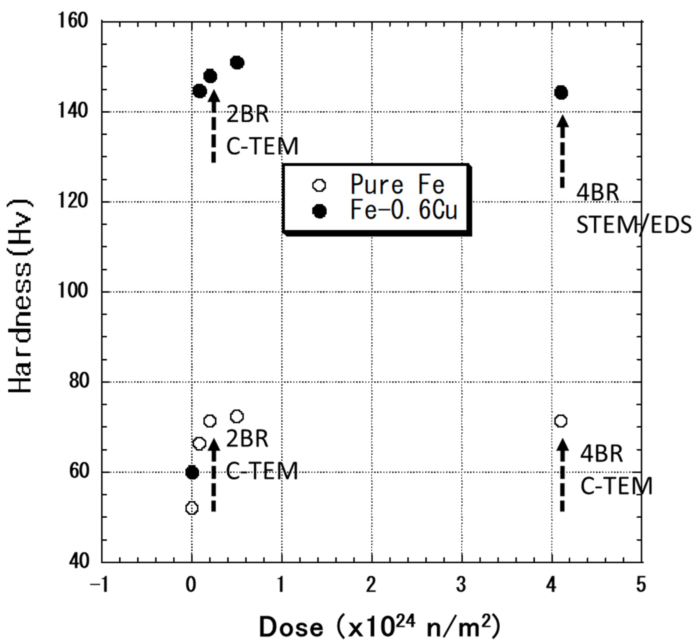
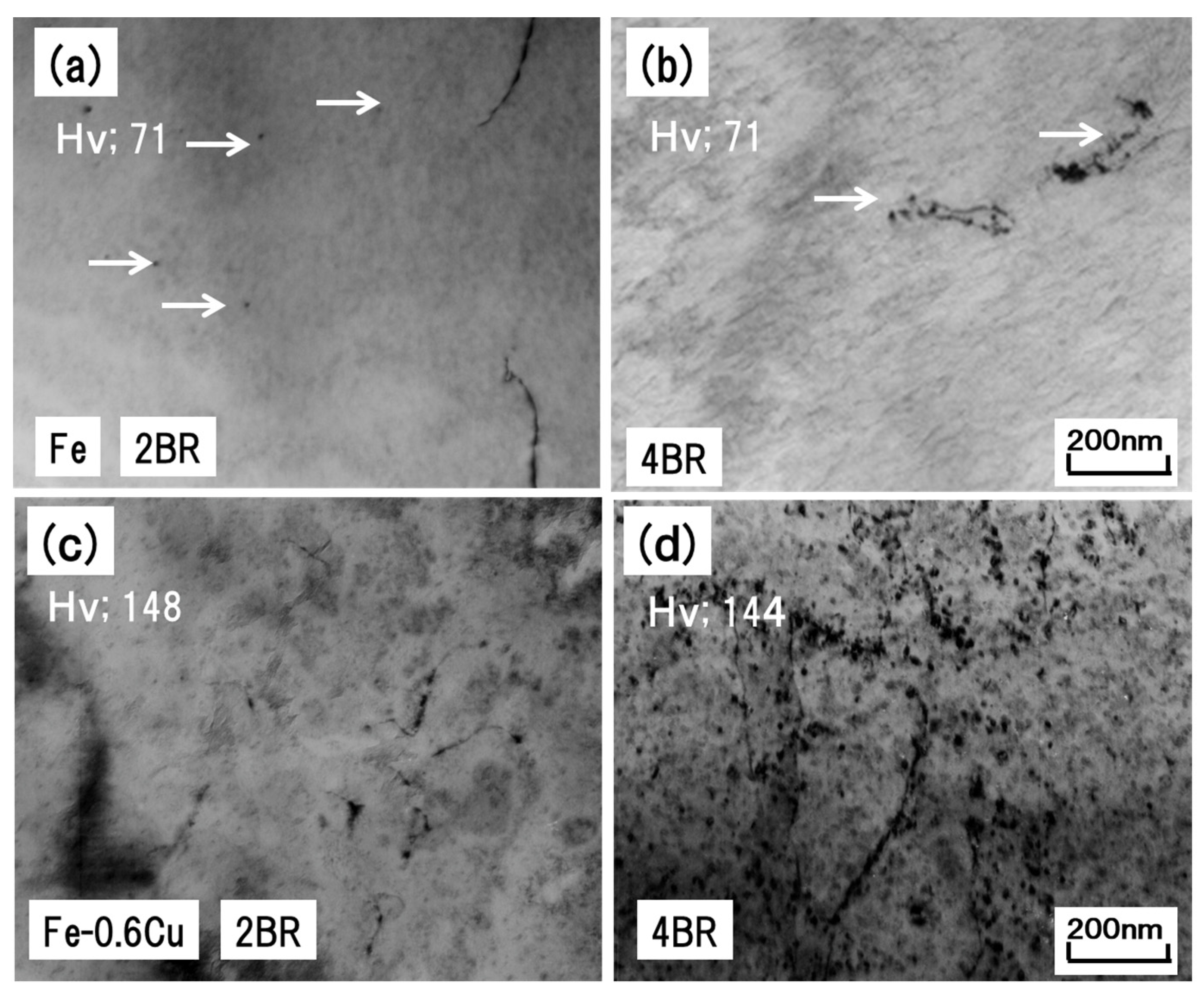
3.1. Dose Dependence of Microstructure and Hardness

Figure 1 shows the radiation-induced hardening of pure Fe and Fe-0.6wt%Cu alloy. The hardness was increased and was saturated at the beginning of neutron irradiation at 290 °C.
Figure 2 shows the microstructure (conventional bright-field image) of Fe-0.6wt%Cu alloy after neutron irradiation. Figure 2 also shows measured hardness of 06M-2BR and 06M-4BR irradiation conditions. Dislocation loop density and size were both increased as the dose increased. The hardness of pure Fe and Fe-0.6wt%Cu was saturated with the starting dose and remained unaffected when the dose was increased.
Figure 3 shows the bright and corresponding weak-beam (dark-field) images of the microstructure of 06M-4BR. Formation and growth of dislocation loops are prominent in the vicinity of pre-existing dislocations. The diffraction pattern of the irradiated area shows the existence of CRPs.
To identify the nature of these small clusters formed at 290 °C, additional electron irradiation using HVEM was performed at room temperature. The electron irradiation of existing interstitial (or vacancy)-type loops shows that they can grow or shrink by absorbing interstitials because the mobility of vacancies in model alloys is very low at room temperature. Figure 4 shows the change in the dislocation loops in Fe-0.6wt%Cu alloy that are formed by the irradiation of 06M-4BR. Using further electron irradiation at room temperature, relatively large loops (indicated with arrows in Figure 4) are identified as interstitial-type dislocation loops. The measured dislocation loop size and density of 06M-4BR are 7.0 nm and 3.0 × 10²¹ m−3, respectively.

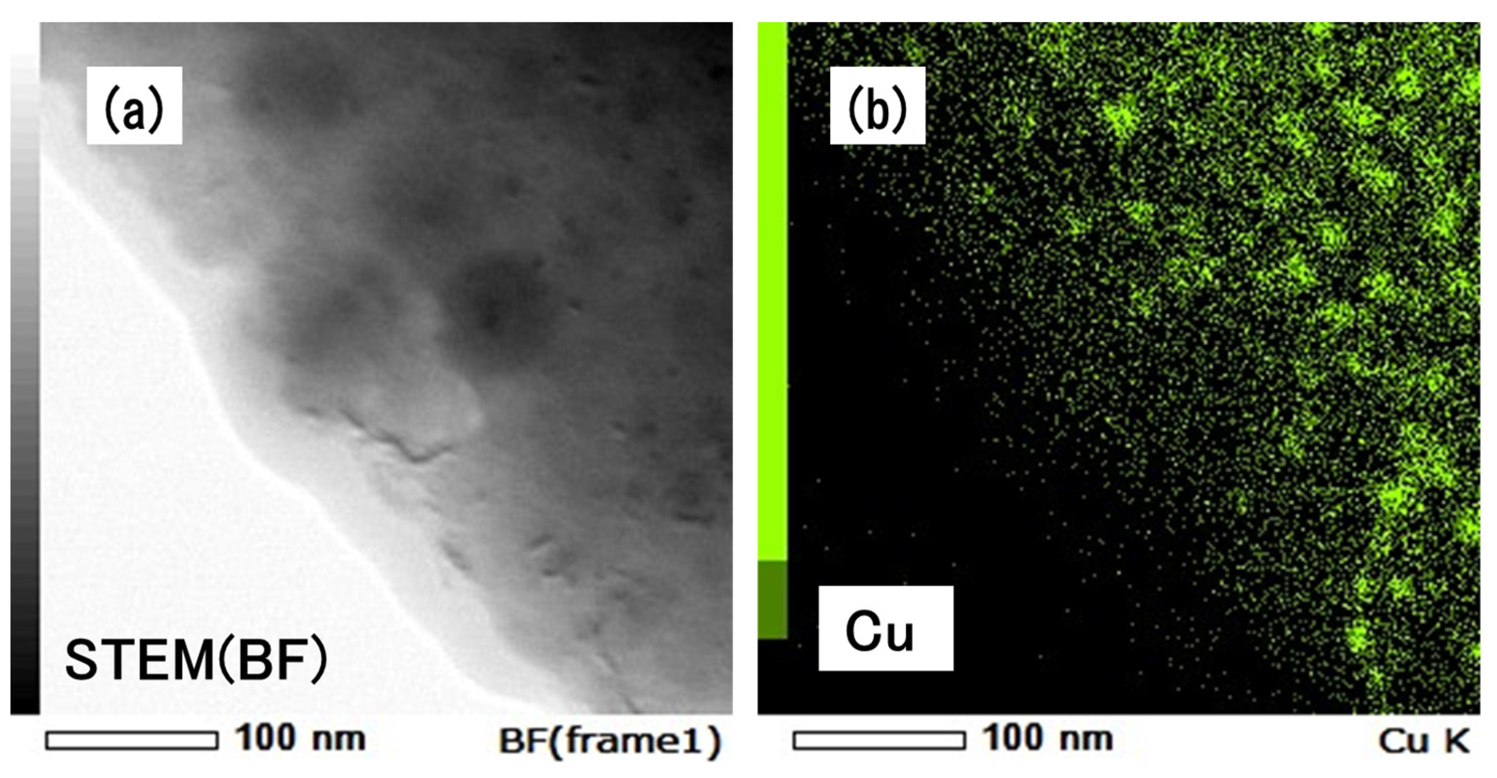
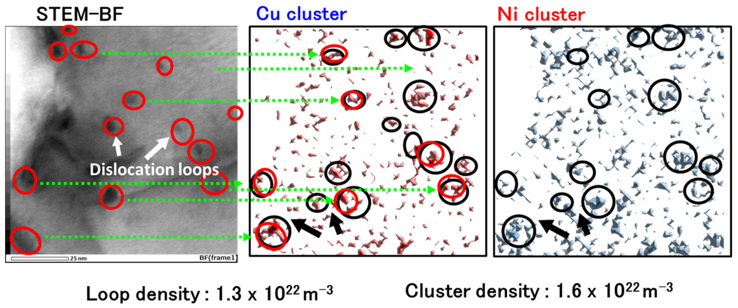
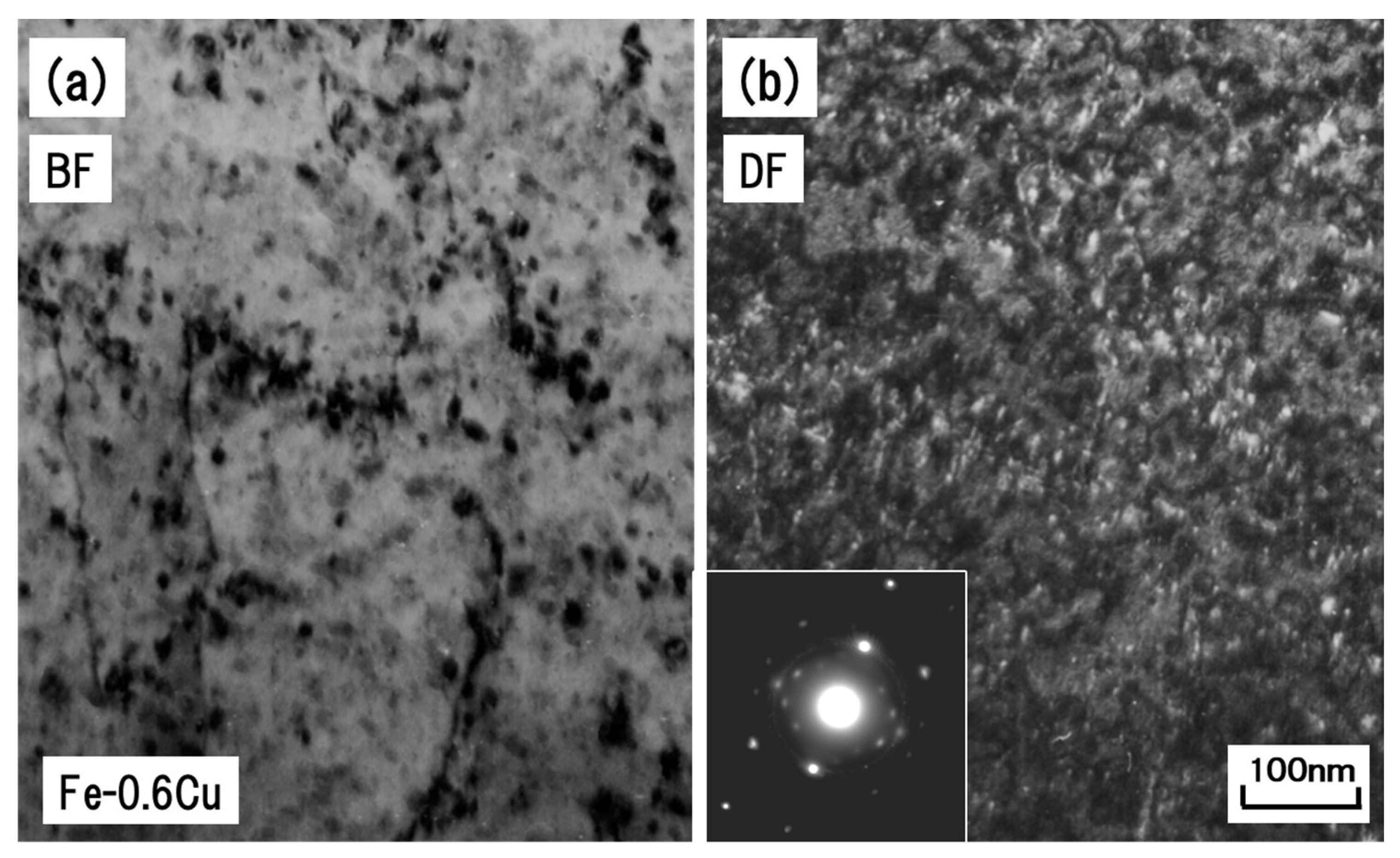
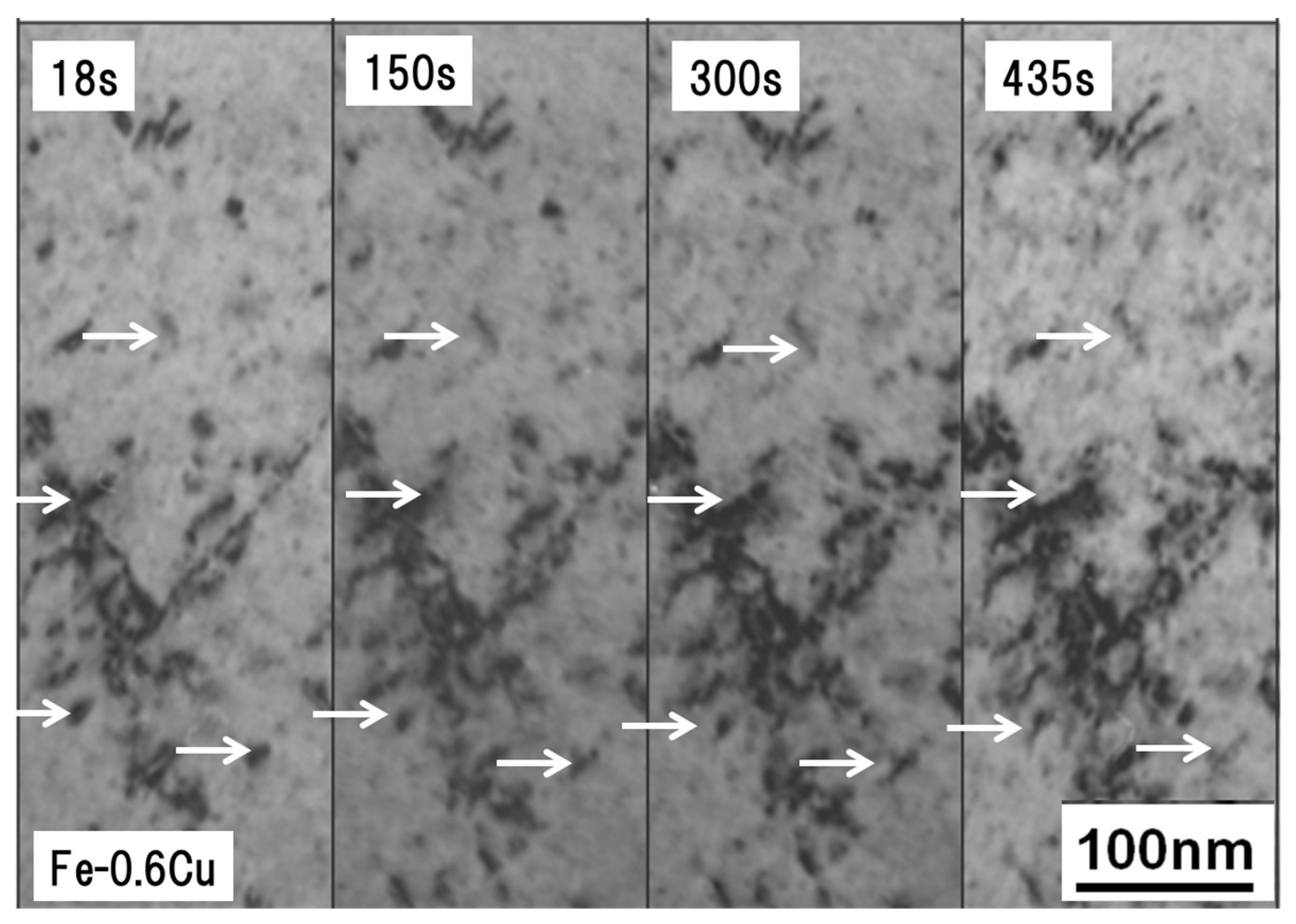
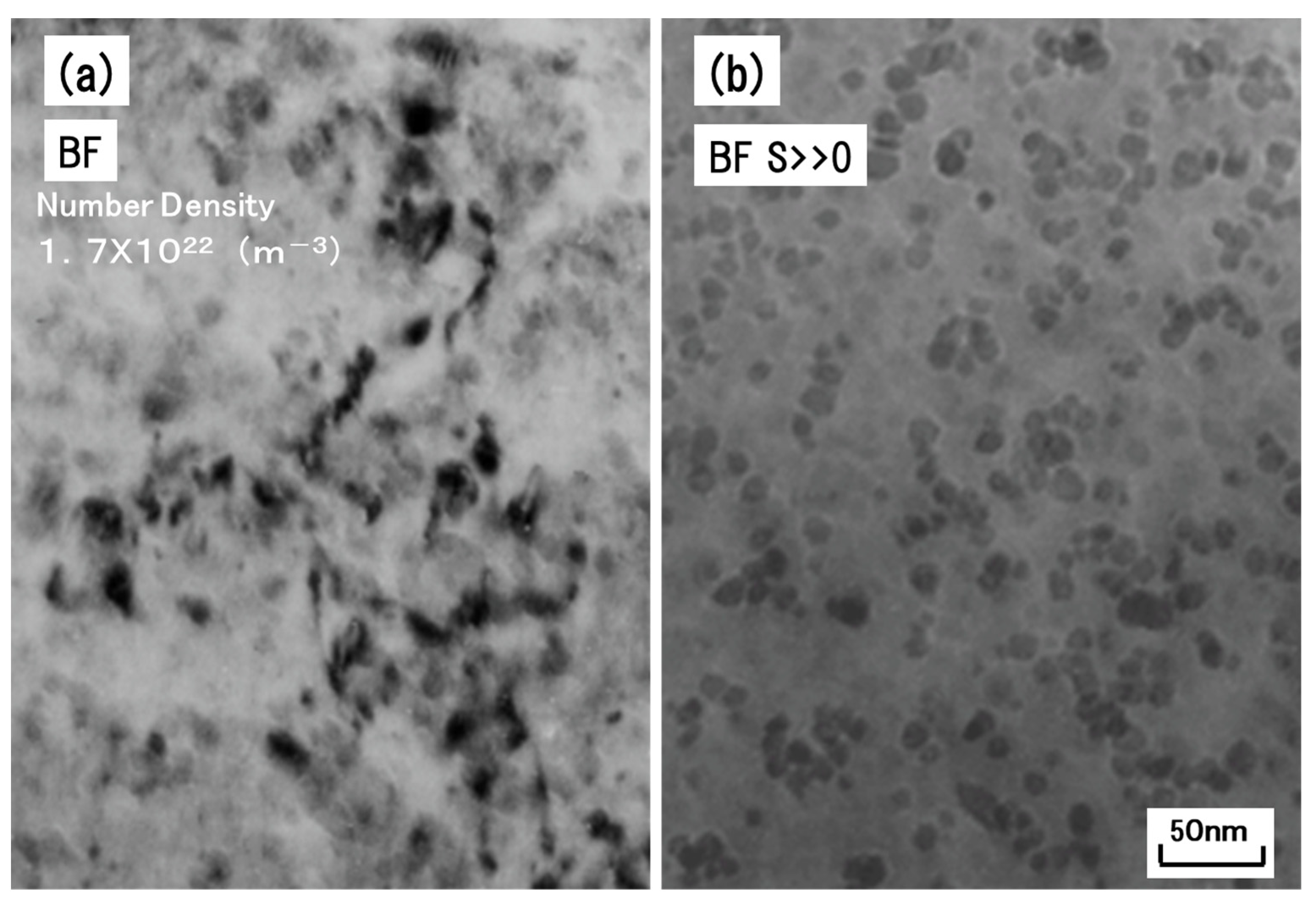
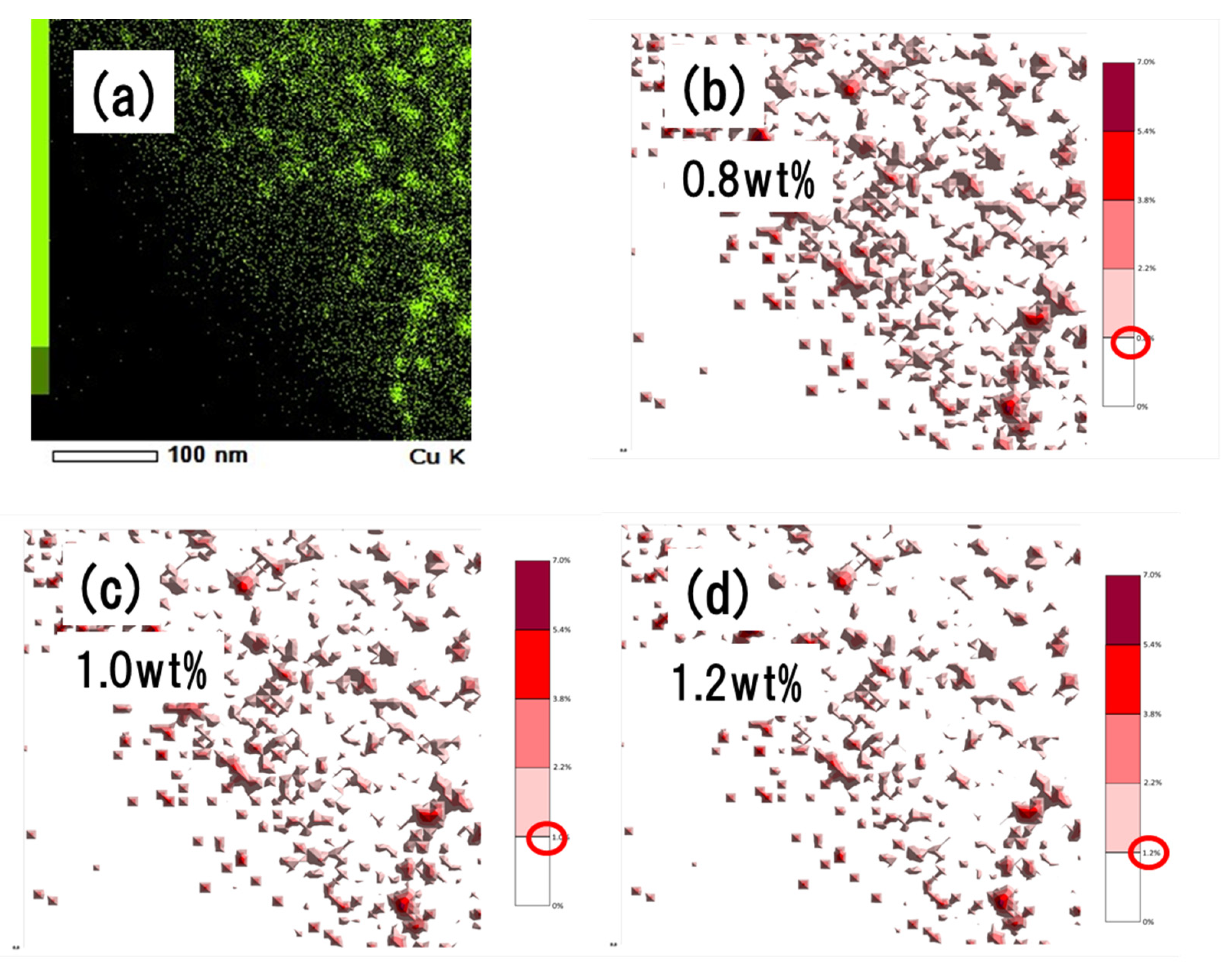
3.2. Dislocation Loops and CRPs Formed in Fe-0.6wt%Cu Alloy and A533B

Figure 5 shows the bright-field image of Fe-0.6wt%Cu alloy after irradiation at 06M-4BR.
By changing the Bragg condition, CRPs in the alloy become visible. By using the technique, the estimated CRP size and density are 10 nm and 1.7 × 10²² m−3, respectively. Figure 6a,b show STEM bright-field images and corresponding Cu atom mapping, respectively. For image acquisition and spectrum analysis for EDS, a 256 × 256 acquisition resolution was applied. After the qualitative analysis calculation at each point, the estimated concentration of the element (i.e., Cu atom) was obtained. To eliminate the Cu background in the matrix, several threshold concentrations of Cu were introduced. Figure 7 shows examples of a qualitative analysis. The positions of CRPs (b)–(d) were obtained through image (a). The comparable 1.2 wt% threshold concentration of CRP formation was found using the measured CRP density (1.7 × 10²² m−3) from the TEM observations. In the case of A533B, some of dislocation loops formed in the alloy were also decorated with CRPs. Therefore, co-segregation of Cu and Ni atoms on dislocation loops were observed in the samples irradiated at the same condition (290 °C, 4.1 × 1024 n/m2) is confirmed (Figure 8).

4. Discussion

It is well known that the radiation induced embrittlement of Fe-based alloy is mainly due to the formation of CRPs, because the CRPs act as obstacles against the dislocation motions [13,14]. The study also shows that the interstitial-type dislocation loop density and size increase with dose escalation. However, as shown in Figure 2, the presence of Cu atoms reduces loop size, meaning that the Cu atoms in pure Fe reduce the growth rate of the dislocation loops. It is known that the growth speed of the interstitial loops is controlled by the mobility of vacancies. By using positron annihilation spectroscopy, Nagai et al. confirmed formation of a vacancy–Cu complex in diluted Fe–Cu alloys consequent of neutron irradiation [14]. A strong binding energy between Cu atoms and vacancies is also obtained by ab initio simulations [15]. As presented in the previous section, many CRPs were nucleated on tangled dislocations. The formation of clusters on dislocations is explained by formation of vacancy–Cu complexes and by segregation of dislocations.
Additionally, dislocation loops and CRPs were observed by TEM and STEM-EDS under higher dose conditions. The contribution of each individual loop or CRP to the yield stress (σj), apart from all other contributions, is determined by the barrier hardening model according to Bacon, Kocks, and Scattergood [16,17]:
σj = αjMμb(Njdj)1/2/3 (j = l:Loop or p:CRP),
where αj is the hardening efficiency, which depends on the nature of the defect and is often assigned a value of 0.4 for small dislocation loops [18,19], and αp(rp) is the size-dependent strength factor for CRPs, which ranges from 0.1 to 0.2 and is computed using a Russell–Brown (RB)-type model [20]. The parameters Nj and dj are the number densities and diameters of the loops and CRPs, respectively. Dislocation loops in bcc structures undergo contrast change depending on the Burgers vector (b) and the diffraction vector (g). Dislocation loops are invisible when the value of g is 200 for gb = 0. For steels, N is the measured value multiplied by 1.5. The Taylor factor (M = 3.06), the shear modulus (μ = 80,700 MPa), and the Burgers vector (b = 0.25 × 10⁻⁹ m) were all performed. The estimated radiation-induced hardening (ΔHv) due to dislocation loops and CRPs formation at 290 °C and a dose of 4.1 × 1024 n/m2 for Fe-0.6wt%Cu alloy were 72 for dislocation loops and 27 for CRPs. The corresponding measured ΔHv value was approximately 85, which is in accordance with the estimated value. These results suggest that radiation-induced hardening for Fe-0.6wt%Cu alloy can be explained by a combination of dislocation loops and CRPs observed by TEM and STEM-EDS.

5. Conclusions

To study the effect of dislocation loops and CRPs on radiation hardening in Fe-based model alloys, neutron irradiation was conducted in BR2 at 290 °C for an Fe-0.6wt%Cu alloy. After irradiation, dislocation loops and CRPs were observed and analyzed by Cs-corrected TEM and STEM-EDS. By using these techniques, simultaneous observation of CRPs of about 10 nm and dislocation loops was possible.
With additional high-voltage electron irradiation at room temperature, these dislocation loops were identified as interstitial-type dislocation loops. Radiation-induced hardening due to neutron irradiation was estimated by the size and density of dislocation loops and CRPs obtained by microscopy. The estimated hardness by barrier hardening model is almost comparable with the measured hardness. These results suggest that simultaneous observation of dislocation loops and CRPs using the Cs-corrected STEM with EDS analysis is essential for the study of radiation-induced hardening in Fe-based alloys.

Author Contributions

Conceptualization, H.W. and Y.K.; investigation (TEM, hardness measurement), T.T. (Tomonari Tanaka) and T.T. (Takukya Turu); supervision, H.W.; project administration, H.W.; funding acquisition, H.W. All authors have read and agreed to the published version of the manuscript.

Funding

This work was supported by a Grant-in-Aid for Science Research (B) 16H04633 and 18H01909 from the Ministry of Education, Culture, Sports, Science and Technology of Japan. This work was also supported in part by the Collaborative Research Program of Research Institute for Applied Mechanics, Kyushu University.

Acknowledgments

Neutron irradiation was performed with BR-2 in SCK CEN in the framework of MICADO project.

Conflicts of Interest

The authors declare no conflict of interest.

References

  1. Odette, G.R. On the dominant mechanism of irradiation embrittlement of reactor pressure vessel steels. Scr. Mater. 1983, 11, 1183. [Google Scholar] [CrossRef]
  2. Lucas, G.E.; Odette, G.R.; Lombrozo, P.M.; Sheckherd, J.W. Effects of Radiation on Materials: 12th International Symposium; ASTM STP 870; American Society for Testing Materials: Philadelphia, PA, USA, 1985; p. 900. [Google Scholar]
  3. Fuji, K.; Ohkubo, T.; Fukuya, K. Effects of solute elements on irradiation hardening and microstructural evolution in low alloy steels. J. Nucl. Mater. 2011, 417, 949–952. [Google Scholar] [CrossRef]
  4. Takeuchi, T.; Kuramoto, A.; Kameda, J.; Toyamam, T.; Naai, Y.; Hasegawa, M.; Ohkubo, T.; Yoshiie, T.; Nishiyama, Y.; Onizawa, K. Effects of chemical composition and dose on microstructure evolution and hardening of neutron-irradiated reactor pressure vessel steels. J. Nucl. Mater. 2010, 402, 93–101. [Google Scholar] [CrossRef]
  5. Lindgren, K.; Boasen, M.; Stiller, K.; Efsing, P.; Thuvander, M. Evolution of precipitation in reactor pressure vessel steel welds under neutron irradiation. J. Nucl. Mater. 2017, 488, 222–230. [Google Scholar] [CrossRef]
  6. Suzuki, M.; Onizawa, K.; Kizaki, M. Effects of Radiation on Materials: 17th International Symposium; ASTM STP 1270; American Society for Testing Materials: Philadelphia, PA, USA, 1996; p. 351. [Google Scholar]
  7. Odette, G.R.; Mader, E.V.; Lucas, G.E.; Phythian, W.J.; English, C.A. Effects of Radiation on Materials: 16th International Symposium; ASTM STP 1275; American Society for Testing Materials: Philadelphia, PA, USA, 1993; p. 373. [Google Scholar]
  8. Kiritani, M.; Tanaka, H. Dynamic studies of defect mobility using high voltage electron microscopy. J. Nucl. Mater. 1978, 69–70, 277–309. [Google Scholar] [CrossRef]
  9. Hirsch, P.; Howie, A.; Nicholson, R.; Pashloy, D.; Whelan, M. Electron Microscopy of Thin Crystals; Butterworths: London, UK, 1965; pp. 263–267, (loop nature); pp. 415–418 (thickness measurements). [Google Scholar]
  10. Kiritani, M.M.; Yoshida, N.; Tanaka, H.; Maehara, Y. Growth of interstitial type dislocation loops and vacancy mobility in electron irradiated metals. J. Phys. Soc. Jpn. 1975, 38, 1677–1686. [Google Scholar] [CrossRef]
  11. Yoshida, N.; Kiritani, M.; Fujita, F.E. Electron radiation damage of iron in high voltage electron microscope. J. Phys. Soc. Jpn. 1975, 39, 170–179. [Google Scholar] [CrossRef]
  12. Abe, H.; Kuramoto, E. Interaction of solutes with irradiation-induced defects of electron-irradiated dilute iron alloys. J. Nucl. Mater. 1999, 271–272, 209–213. [Google Scholar] [CrossRef]
  13. Tobita, T.; Nakagawa, S.; Takeuchi, T.; Suzuki, M.; Ishikawa, N.; Chimi, Y.; Saitoh, Y.; Soneda, N.; Nishida, K.; Ishino, S.; et al. Effects of irradiation induced Cu clustering on Vickers hardness and electrical resistivity of Fe-Cu model alloys. J. Nucl. Mater. 2014, 452, 241–247. [Google Scholar] [CrossRef]
  14. Nagai, Y.; Tang, Z.; Hasegawa, M.; Kanai, T.; Saneyasu, M. Irradiation-induced Cu aggregations in Fe: An origin of embrittlement of reactor pressure vessel steels. Phys. Rev. B 2001, 63, 134110. [Google Scholar] [CrossRef]
  15. Vincent, E.; Becquart, C.S.; Domain, C. Ab initio calculations of self-interstitial interaction and migration with solute atoms in bcc Fe. J. Nucl. Mater. 2006, 359, 227–237. [Google Scholar] [CrossRef]
  16. Bacon, D.J.; Kocks, U.F.; Scattergood, R.Q. The effect of dislocation self-interaction on the Orowan stress. Philos. Mag. 1973, 28, 1241–1263. [Google Scholar] [CrossRef]
  17. Queyreau, S.; Monner, G.; Devincre, B. Orowan strengthening and forest hardening superposition examined bydislocation dynamics simulations. Acta Mater. 2010, 58, 5586. [Google Scholar] [CrossRef]
  18. Lucas, G.E. The evolution of mechanical property change in irradiated austenitic stainless steels. J. Nucl. Mater. 1993, 206, 287–305. [Google Scholar] [CrossRef]
  19. Bergner, F.; Pareige, C.; Hernendez-Mayoral, M.; Malerba, L.; Heintze, C. Application of a three-feature dispersed-barrier hardening model to neutron-irradiated Fe-Cr model alloys. J. Nucl. Mater. 2014, 448, 96–102. [Google Scholar] [CrossRef]
  20. Russell, K.E.; Brown, L.M. A dispersion strengthening model based on differing elastic moduli applied to the iron-copper system. Acta Metall. 1972, 20, 969–974. [Google Scholar] [CrossRef]
Figure 1. Dose dependence of radiation-induced hardening of pure Fe and Fe-0.6wt%Cu alloy.
Metals 12 00729 g001
Figure 2. Microstructure of pure Fe and Fe-0.6wt%Cu alloy irradiated at 290 °C: (a,c) 06M-2BR, (b,d) 06M-4BR. Dislocation loops were shown by arrows.
Metals 12 00729 g002
Figure 3. Bright-field (a) and corresponding dark-field (weak beam) (b) images of Fe-0.6wt%Cu alloy irradiated at 290 °C with an irradiation dose of 4.1 × 1024 n/m2. The diffraction pattern of (100) plane and precipitates (CRPs) were also inserted in (b).
Metals 12 00729 g003
Figure 4. Microstructural evolution of the neuron-irradiated Fe-0.6wt%Cu alloy during electron irradiation at 1.0 MeV at room temperature. Irradiation time (s) is inserted in the figure. The nature of the dislocation loop (shown by arrows) was identified as interstitial type.
Metals 12 00729 g004
Figure 5. Images from CRPs using different Bragg conditions; (a) S ~ 0, (b) S >> 0. S is a variation from Bragg condition. Dislocation and dislocation loops are only visible in the case of S ~ 0.
Metals 12 00729 g005
Figure 6. STEM bright-field image (a) and corresponding Cu atom map (b) for Fe-0.6wt%Cu alloy.
Metals 12 00729 g006
Figure 7. Qualitative analysis of Cu wt% of the sample to show that the Cu cluster threshold values were introduced: (a) Cu atom map, (b) 0.8 wt%, (c) 1.0 wt%, and (d) 1.2 wt%. Threshold values are shown by red circles in the figure.
Metals 12 00729 g007
Figure 8. Co-segregation of Cu and Ni atoms formed in A533B and irradiated at 290 °C at a dose of 4.1 × 1024 n/m2. Cu cluster (red circles), Ni cluster (black circles).
Metals 12 00729 g008
Table 1. Chemical composition of the materials used in the study (wt%).
MaterialsNominal Composition(wt%)/Impurities
Pure Fe <30 ppm C
Fe-0.6Cu0.6 Cu (<30 ppm C)
A533B steel0.14 C, 0.003 S, 0.017 P, 0.19 Si, 1.47 Mn
0.64 Ni, 0.14 Cr, 0.51 Mo, 0.164 Cu
Table 2. Irradiation cycles and neutron fluence (n/m2) used in the study.
Irradiation CycleFluence (n/m2)
06M-1BR8.3 × 1022
06M-2BR2.0 × 1023
06M-3BR5.0 × 1023
06M-4BR4.1 × 1024
Publisher’s Note: MDPI stays neutral with regard to jurisdictional claims in published maps and institutional affiliations.

