Article

Characterizing Changes in Grain Growth, Mechanical Properties, and Transformation Properties in Differently Sintered and Annealed Binder-Jet 3D Printed 14M Ni–Mn–Ga Magnetic Shape Memory Alloys

1
Department of Mechanical Engineering and Materials Science and Engineering, University of Pittsburgh, Pittsburgh, PA 15261, USA
2
Helmholtz-Zentrum Berlin für Materialien und Energie GmbH, Hahn-Meitner-Platz 1, 14109 Berlin, Germany
3
School of Engineering Science, Lappeenranta-Lahti University of Technology LUT, 53850 Lappeenranta, Finland
*
Author to whom correspondence should be addressed.
Current address: Department of Mechanical, Materials and Aerospace Engineering, Illinois Institute of Technology, Chicago, IL 60616, USA.
Metals 2022, 12(5), 724; https://doi.org/10.3390/met12050724
Submission received: 20 March 2022 / Revised: 13 April 2022 / Accepted: 20 April 2022 / Published: 24 April 2022
(This article belongs to the Special Issue Recent Development in Magnetic Shape Memory Alloys)

Abstract

:
Ni–Mn–Ga Heusler alloys are multifunctional materials that demonstrate macroscopic strain under an externally applied magnetic field through the motion of martensite twin boundaries within the microstructure. This study sought to comprehensively characterize the microstructural, mechanical, thermal, and magnetic properties near the solidus in binder-jet 3D printed 14M Ni50Mn30Ga20. Neutron diffraction data were analyzed to identify the martensite modulation and observe the grain size evolution in samples sintered at temperatures of 1080 °C and 1090 °C. Large clusters of high neutron-count pixels in samples sintered at 1090 °C were identified, suggesting Bragg diffraction of large grains (near doubling in size) compared to 1080 °C sintered samples. The grain size was confirmed through quantitative stereology of polished surfaces for differently sintered and heat-treated samples. Nanoindentation testing revealed a greater resistance to plasticity and a larger elastic modulus in 1090 °C sintered samples (relative density ~95%) compared to the samples sintered at 1080 °C (relative density ~80%). Martensitic transformation temperatures were lower for samples sintered at 1090 °C than 1080 °C, though a further heat treatment step could be added to tailor the transformation temperature. Microstructurally, twin variants ≤10 μm in width were observed and the presence of magnetic anisotropy was confirmed through magnetic force microscopy. This study indicates that a 10 °C sintering temperature difference can largely affect the microstructure and mechanical properties (including elastic modulus and hardness) while still allowing for the presence of magnetic twin variants in the resulting modulated martensite.

1. Introduction

Ni2–Mn–Ga-derivative Heusler materials are considered magnetic shape memory alloys (MSMAs) and demonstrate a large mechanical strain under an externally applied magnetic field [1,2]. This magnetic-field induced strain (MFIS) occurs through twin variant reorientation in the low-temperature ferromagnetic martensite phase, due in part to its large magnetocrystalline anisotropy [2,3]. Ni–Mn–Ga MSMAs were shown to deform by up to 12% with a fast response time in the order of a few microseconds, high working frequencies up to 100 kHz, and long lifetimes exceeding 107 cycles [4,5,6,7,8,9]. These properties have generated interest in alternative materials for use as actuators and sensors from the nano- to macro-scale [10,11,12]. Additionally, when the Curie and phase transformation temperatures overlap, Ni–Mn–Ga(–X) alloys were shown to exhibit a magnetocaloric effect useful in refrigeration, sensors, and energy harvesters [10,12,13].
Significant MFIS requires a compliant microstructure for the motion of martensite twin boundaries. In particular, the grain size, present phases, compositional additions, and processing and fabrication conditions are engineering choices that must be considered when designing MSMAs exhibiting MFIS. For example, Lázpita et al. [14] showed that fine-grained and randomly textured Ni–Mn–Ga samples exhibit hardly any MFIS under an external magnetic field due to internal microstructural constraints on the twin-boundary motion. Furthermore, surface defects strongly influence twin-boundary stresses and can stabilize fine twin-boundary structures [15,16,17,18,19]. This places a particular emphasis on the processing and fabrication of Ni–Mn–Ga alloys aiming to maximize the MFIS by producing a microstructure with fewer defects, grain boundaries, and interstitials.
To promote MFIS in polycrystalline MSMAs, there has been increasing interest in manufacturing porous Ni–Mn–Ga polycrystalline samples [20]. Unlike fully-densified polycrystalline samples containing a large surface area of grain boundaries, porous Ni–Mn–Ga structures reduce constraints and allow the martensitic twins to move more freely, decreasing the activation stress required to achieve motion [5,9,14,20,21]. A proposed method for manufacturing samples with intentional porosity is through additive manufacturing, where single layers of material are deposited and bound one layer at a time [22]. So far, Taylor et al. [23] have performed work on 3D printed inks using elemental powders, and Mostafaei et al. [24,25] and Caputo et al. [26] have discussed the use of binder-jet 3D printing (or binder jetting) as a fast and cost-effective additive manufacturing technique with the capability to produce complex shapes with tunable porosity. Post-processing sintering and heat-treatment allow user-controlled porosity levels to be achieved following printing through various parameters including sintering temperature, time, and environment [27].
In this study, binder-jet 3D printed Ni50Mn30Ga20 (at.%) samples were sintered at two different temperatures and additionally annealed (four samples in total). Microstructural characteristics including lattice parameters, martensite modulation, and unit cell size were correlated to grain size, porosity, and hardness measurements. Properties including martensitic transformation temperature, surface magnetic structure, and magnetization behavior were correlated to post-processing parameters.

2. Materials and Methods

Sample preparation procedures for materials used in this experiment are provided in detail in [24] with a brief summary given here. Polycrystalline ingots were fabricated using induction melting on high-purity elemental Ni, Mn, and Ga powder. Using energy-dispersive X-ray spectroscopy (EDS), the composition of the ingot was determined to be Ni49.7±0.5Mn30.0±1.0Ga20.3±0.6 (at.%). The ingots were broken up, ball-milled using a planetary mill (Retsch Inc., Haan, Germany), and sieved using a US 230 ASTM E-11 standard mesh sieve (Fisherbrand, Pittsburgh, PA, USA). The powder was then binder-jet 3D printed using an ExOne X1-Lab printer (The ExOne Company, Irwin, PA, USA). Printing parameters for this fabrication step are as follows: layer thickness of 100 μm, spread speed of 20 mm/s, feed:build powder ratio of 2, drying time of 40 s, and binder saturation of 80%. Additionally, powder layers were bound with an ethylene glycol monomethyl ether and diethylene glycol solvent binder. As-printed green samples were cured at 200 °C for 8 h in air then encapsulated in a glass tube with high purity titanium sponge (as a sacrificial oxidizer) under an argon atmosphere of approximately 40 kPa at room temperature. Encapsulated samples were heated at 4 °C/min to the sintering temperature of 1080 °C or 1090 °C using a Lindberg tube furnace (Lindberg Blue, Asheville, NC, USA), held at this temperature for 2 h, then air-cooled. Additionally, a heat-treatment procedure was performed on one sample of each sintering temperature, which comprised of an annealing step at 1000 °C for 10 h and an ordering step at 700 °C for 12 h, for a total of four samples under investigation.
Neutron diffraction data were obtained for Ni–Mn–Ga samples from the E3 beamline (wavelength λ = 1.47318 ± 0.00056 Å) at the Helmholtz-Zentrum Berlin für Materialien und Energie (HZB) [28]. The beamline utilized a bent Si (400) focusing monochromator and a 30 cm × 30 cm position-sensitive detector (PSD). The detector center was positioned at 2θ values of 42°, 53°, 64°, and 75° while Ω (sample stage, see Figure 1) was rotated in increments of 2° from −90° to 0°, and the intensity on the detector was recorded. A schematic of the goniometer stationed at beamline E3 is shown in Figure 1 with relevant angles illustrated [29]. Area detector raw were was extracted utilizing in-house plotting software, and Gaussian peaks were fit to the diffraction curves using OriginPro software (2018b, OriginLab, Northampton, MA, USA).
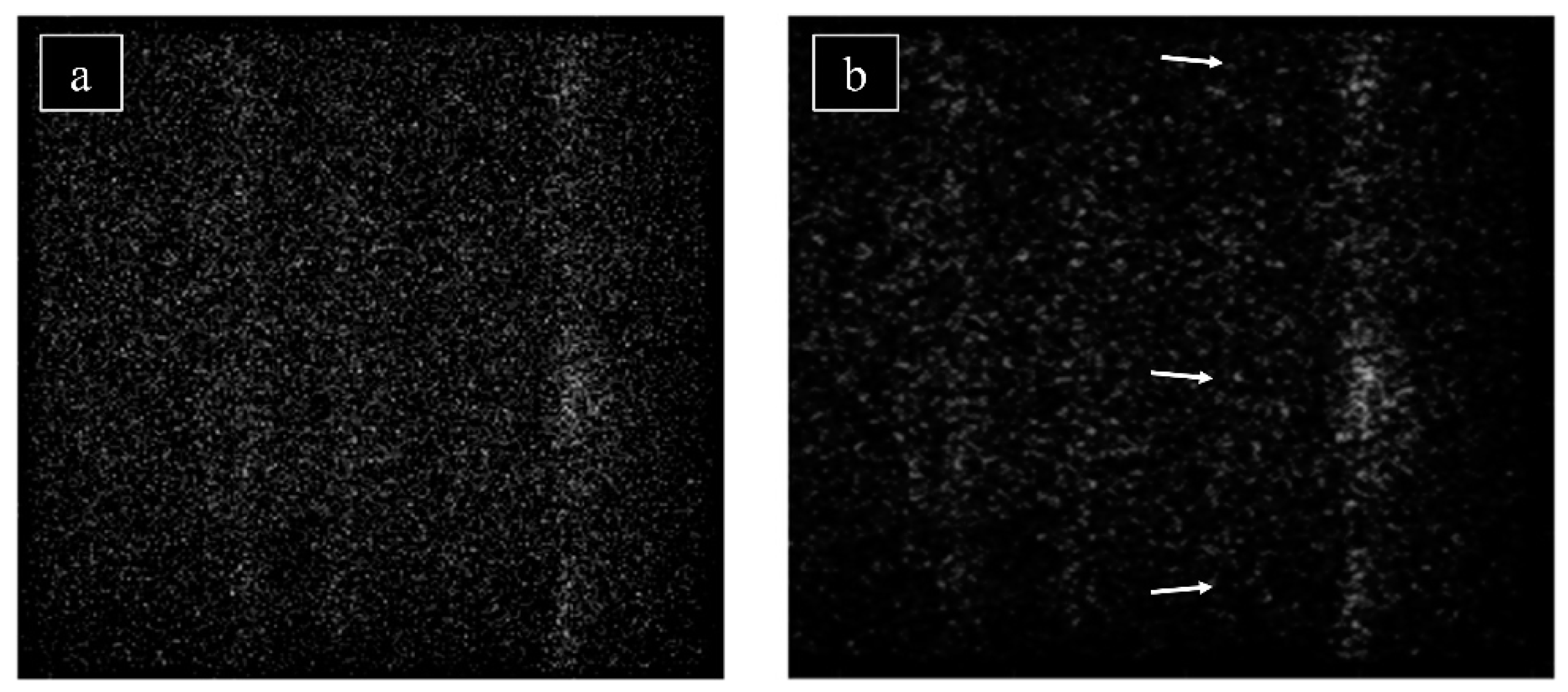
Raw neutron diffraction data were extracted image-by-image within the 2θ = 42° regime using ImageJ image analysis software (NIH, Bethesda, MD, USA) for conversion [30,31] and an in-house MATLAB program (MathWorks Inc., Natick, MA, USA) for processing. For the 256 × 256 pixel array, the program isolated, enhanced, and clarified pixel clusters likely corresponding to individual grains satisfying Bragg diffraction criteria. An exemplary frame highlighting grain clustering of the 1090 °C sintered-only sample in the region = 75° at Ω = −90° is shown in Figure 2a. For all raw images (i.e., all Ω steps) in the 2θ = 42° regime, pixel clusters were counted following image processing for all four samples to provide qualitative interpretation of the grain size.
Samples were mounted, polished, and etched using a Tegramin-25 automatic polisher (Struers, Ballerup, Denmark) and imaged for grain size using a Keyence VHX-600 digital optical microscope (Keyence, Osaka, Japan) with a VH-Z100 lens. Grain sizes from several micrographs were measured and compared using ImageJ image analysis software through quantitative stereology of the etched surfaces utilizing a method previously outlined in [32]. Differential interference contrast (DIC) microscopy was performed using a Nikon Optiphot (Nikon, Scotia, NY, USA) to observe twinning on the sample surfaces.
Mechanical behavior of the samples was quantified through nanoindentation on mounted materials using a Hysitron TI 950 Triboindenter (Bruker, Tuscon, AZ, USA) with a Berkovich indentation tip. The following trapezoidal loading function was used for testing: linear loading from 0 to 10 mN at a rate of 2 mN/s, constant applied load of 10 mN for 5 s, and linear unloading from 10 to 0 mN at a rate of 2 mN/s. Tests were performed at various distances from pores on the sample surface, and the reduced Elastic modulus (Er) and hardness were recorded in GPa. Ten load–displacement curves were collected and analyzed for each of the four samples to isolate and identify homogenous dislocation motion. Mechanical properties identified via nanoindentation were considered in relation to material densification throughout the sintering process. Relative density of the four samples was determined using Archimedes’ principle.
In order to identify first- and second-order major transformation temperatures, differential scanning calorimetry (DSC) was performed using a DSC 250 (TA Instruments, New Castle, DE, USA) on the four investigated samples in a temperature window encapsulating the martensitic phase transformation and Curie temperatures. Cut samples were weighed and ramped at 5 °C/min from 40 °C to 120 °C, held at 120 °C for one minute, and then ramped at 5 °C/min from 120 °C to 40 °C. Major peaks and transformation temperatures were identified, noting the expected presence of a significant thermal hysteresis signature in Ni–Mn–Ga Heusler alloys. On heating, the austenite transformation is fully described by the austenite start (AS), austenite finish (AF), and austenite peak (AP) temperatures. Similarly, the martensite transformation is described by martensite start (MS), martensite finish (MF), and martensite peak (MP) temperatures on cooling. The average transformation temperature (Ttrans) averaging the martensite and austenite transformation peaks is also reported. Finally, the Curie temperature (TC) was determined for all samples.
Vibrating sample magnetometry (VSM) was performed using a series 7400 model vibrating sample magnetometer (Lakeshore, Westerville, OH, USA) and magnetization curves in an external magnetic field (±1.5 T) were analyzed to determine saturation magnetization and magnetic coercivity. Additionally, a set of samples sintered at 1080 °C and 1090 °C (non-heat-treated) were electropolished at a constant voltage of 12 V at −20 °C in an electrolyte solution containing a 3:1 volumetric ratio of ethanol to 60% HNO3. Atomic force microscopy (AFM) and magnetic force microscopy (MFM) was performed using an Park XE7 atomic force microscrope (Park Systems, Suwon, Korea) on areas identified (using polarized light microscopy) as regions containing highly dense twin boundaries.

3. Results and Discussion

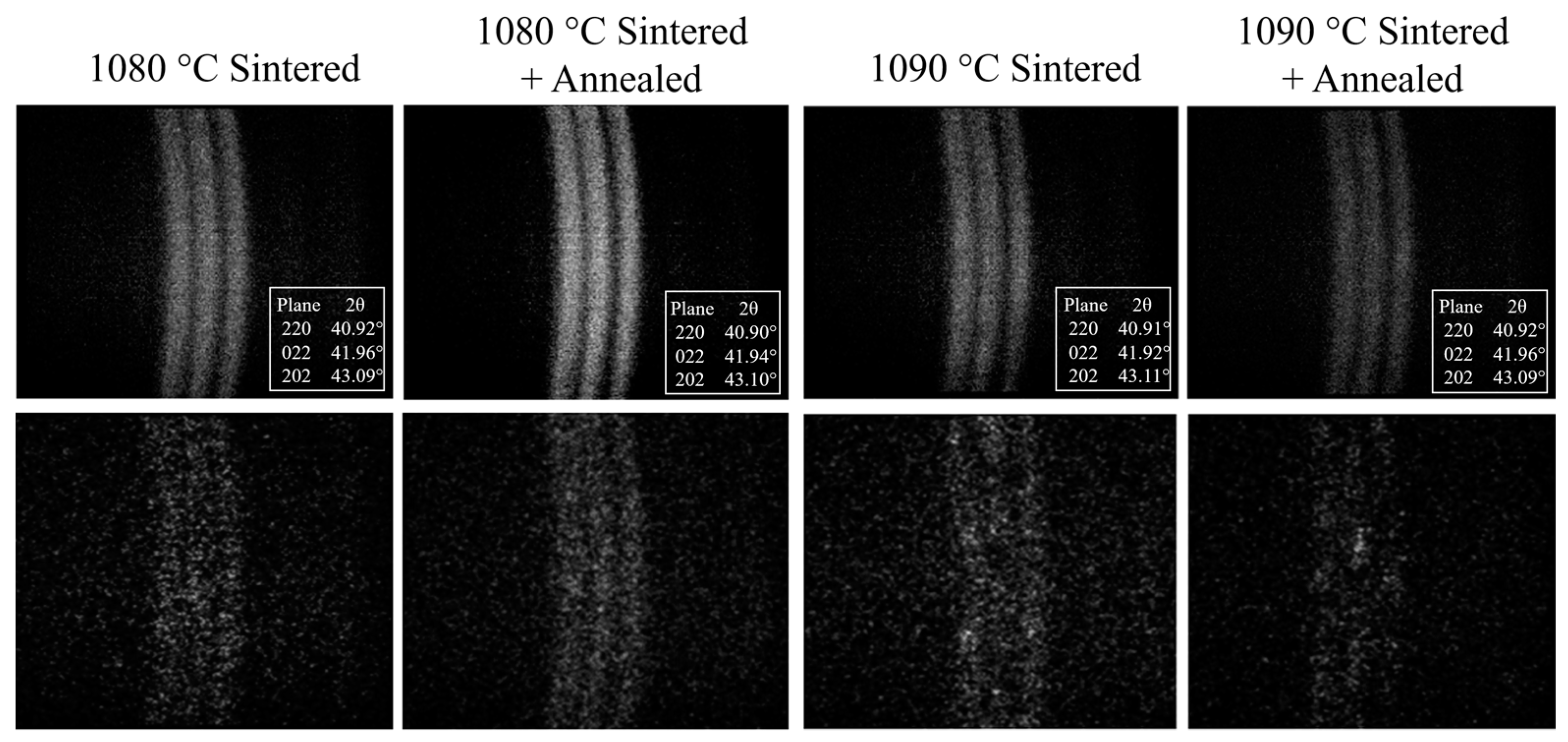
McIntyre discussed that it is possible to identify single crystalline regions in a material using neutron diffraction area detector raw data [33]. It is expected that large clusters in various regions of the raw data (e.g., in Figure 2) correspond to a distinct single grain or crystal which reflects all permissible (hkl) lattice planes according to the Bragg geometry. In other words, by processing individual detector images and observing grain clusters, the relative size of grains can be qualitatively compared. Figure 3 (bottom row) shows examples of processed single Ω detector images of the 2θ = 42° position. It follows that larger grains should be present in a Ω sweep containing large and coherent clusters. It is observed that the 1090 °C sintered samples have more distinguishable diffraction clusters compared to the 1080 °C sintered samples, which show more continuous Bragg diffraction ring sections.
Figure 3 (top row) shows an example of an integrated detector image following the processing described prior. The integrated diffraction images at the 2θ = 42° position were used to identify the martensite phase at room temperature. These three rings correspond to the (220) lattice plane family of 14M martensite for all four samples. The lattice parameters were calculated using the (400) and (220) lattice plane families using a cubic Cartesian coordinate system with an assumed orthorhombic unit cell (α = β = γ = 90°). The c/a ratio is similar for all samples (between 0.8942 and 0.8965) and corresponds to a 14M martensitic structure [24]. A summary of the lattice parameters determined by neutron diffraction, including c/a ratio and unit cell volume, is shown in Table 1.
A qualitative grain size comparison by counting diffraction area clusters was conducted for all samples using an entire Ω sweep (46 images at 2° increments) in the 2θ = 42° regime. Each Ω image was processed as described above, and distinct and coherent clusters in the area detector diffraction images through subjective human interpretation. Through this procedure, nearly three times the number of distinct clusters were identified in the 1090 °C sintered samples (nearly 70 counted for each) compared to the 1080 °C sintered samples (nearly 25 counted for each). The large difference in counted clusters suggests that the 10 °C increase in sintering temperature has more than doubled the number of crystallites large enough to be identifiable via neutron diffraction and, thus, has a measurable impact on the final grain size. It was also determined that the optional heat-treatment step used here does not contribute significantly to grain growth. Overholser et al. [34] reported a solidus temperature of 1088 °C for samples of composition Ni50Mn30Ga20, suggesting the possibility of at least partial super-solidus liquid phase sintering of the binder-jet 3D printed Ni–Mn–Ga samples sintered at 1090 °C. Mostafaei et al. [24] identified similar sintering behavior by investigating the sintering characteristics of binder-jet 3D printed Ni–Mn–Ga at various temperatures near the solidus. This is observed to coincide with massive densification (~80% to ~95%) of the microstructure through the 10 °C sintering temperature increase, as seen in Table 1. See Supplementary Figure S1 for example SEM images of observable grain boundaries on the material microstructure and Supplementary Figure S2 of a micrograph of an etched sample with marked grain boundaries.
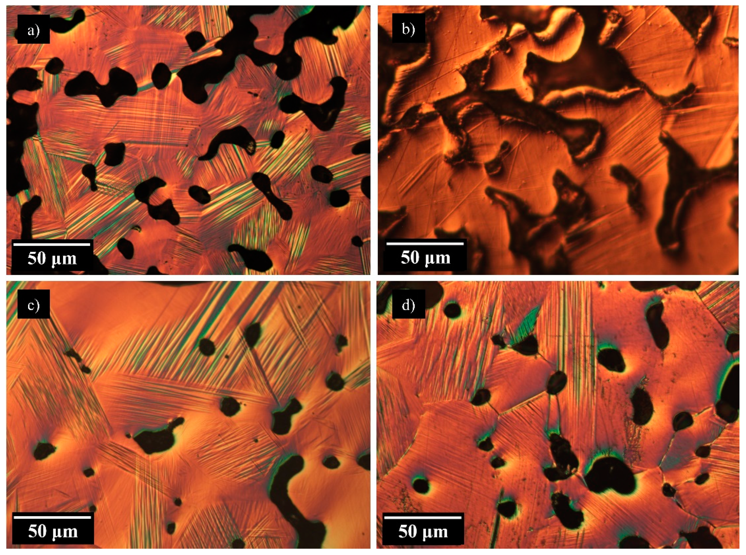
Optical microscopy was applied to visually identify grain boundaries and distinguish individual grains on various cross-sectional areas of magnification identical for all samples (see Table 1 for average equivalent grain diameter). This quantitative approach to grain size identification provides that a sintering temperature increase of 10 °C almost doubles the grain diameter. This confirms the qualitative interpretation that the increase in visible clusters on neutron diffraction images through increased sintering temperature increases grain sizes while the additional heat-treatment shows little effect. Additionally, DIC micrographs for all four samples (presented in Figure 4) show fine twins that are primarily ≤10 μm in width, with some twins showing a width of approximately 1–2 μm. Twin boundaries, which separate the twin variants within crystallite regions, are a requirement for MFIS. Larger grains will contain less grain boundary surface area per volume, reducing twin-boundary motion incompatibilities. Although the literature has discussed the introduction of intentional porosity to reduce the internal constraints on the twin variant reorientation, large densification observed by sintering at 1090 °C largely purges these intentional pores. Chmielus et al. [21] demonstrated large MFIS (up to 8.7%) for polycrystalline foams with pores smaller than the average grain size. Clearly, both grain size and porosity percentage can be adjusted through the introduction of a sintering step, however, the interplay between grain size and pore sizes should be explored as a function of sintering temperature to further optimize MFIS. Porosity characterization could be explored using micro-computed X-ray tomography to identify and analyze pore channels and isolated pore features and dimensions (utilized by our group previously to determine relative density in [24]).
Nanoindentation results, summarized in Table 1, show that among the four samples, the 1080 °C non-heat-treated sample has the lowest hardness, and the samples sintered at 1090 °C have a larger hardness and reduced elastic moduli. The presented data in Table 1 provide that the effect of the heat-treatment step on the final relative density, much like the effect on grain size, is largely negligible. Increased hardness suggests that densification of the sample results in a strengthening of the matrix while opposing the effect of Hall–Petch. The results obtained here on the relative density are comparable to our previous paper [24] and suggest large densification is possible once the solidus temperature is achieved, and a corresponding increase in relative density resulting from partial super-solidus liquid phase sintering was reflected in the reduced elastic modulus increase. The following discussion provides a quantitative approach to the mechanical properties’ relationship to densification.
Gibson and Ashby [35] predict the following relationship for the elastic modulus provided the porosity is homogenous:
E * E s = k ( ρ * ρ s ) 2
Here, E* and ES are the foam (as-printed porous material sample) elastic modulus and bulk (theoretical 100% relative density) elastic modulus, and ρ* and ρS are the foam density and bulk density, respectively. Provided an indentation procedure follows Hertzian contact mechanics, the reduced modulus can be determined as a function of the specimen and indenter properties [36]. Provided below is a fundamental equation that elucidates the elastic moduli through material contact (for example, between an indenter and specimen):
1 E r = 1 ν 2 E + 1 ν i 2 E i
where E, Ei, and Er are the specimen elastic modulus, indenter elastic modulus, and reduced elastic modulus, respectively, and ν and νi are the Poisson’s ratio of the specimen and indenter, respectively. These two equations provide that reduced elastic modulus (and correspondingly, the foam and bulk elastic modulus), is a function of porosity. An example of this relationship was observed in a study by Chen et al. [37], where nanoindentation was applied to porous lanthanum-based perovskite-structured thin films sintered at various temperatures and elastic modulus and hardness were reported. It was shown here that increased porosity could decrease the elastic modulus exceeding an order of magnitude. Using the commonly assigned Poisson’s ratio of 0.3 [38] and the literature values for the Berkovich indenter properties [39], the foam elastic moduli for the four different samples were determined. Furthermore, utilizing Equation (1) and assuming k = 1, the bulk elastic modulus was calculated and is provided in Table 1 for each sample. The literature does not provide data for the elastic modulus of bulk Ni50Mn30Ga20 in the 14M state despite the discussion that the mechanical properties are highly sensitive to alloying additions and compositional variance. However, our values are comparable to Kart and Cagın, who utilized first-principle calculations to determine the elastic modulus of 5M stoichiometric Ni–Mn–Ga to be 144 GPa at 0 K (7M is omitted in this work due to the large computational requirements) [40]. Further work by Kustov et al. [41] reported a significant softening (five to ten times lower) of the elastic modulus values depending on crystallographic direction and temperature for Ni–Mn–Ga. We note that nanoindentation had been performed in this study on mechanically ground, polished, and etched samples, through which minor surface stress and roughness likely accumulated. It should also be noted that the samples in this study have not been previously mechanically trained (see [21] for more details regarding the training process), failing to reduce the twinning stress in this study and reducing twin-boundary motion compliancy.
Finally, SEM imaging was used following nanoindentation to view indents and observe possible twin variant build-up at the indented boundary. In all micrographs except one, variant build-up was absent, suggesting that twin variants may have achieved motion underneath the sample interface or that twin variant motion was not present entirely (see Supplementary Figure S3 as exemplary SEM micrographs of the indent (Figure S3a) with twins visible at the indent and (Figure S3b) without twins). This suggests that twin variant reorientation through the movement of twin boundaries was largely negligible during nanoindentation and the corresponding results. This is also supported by the absence of significant mechanical pop-in behavior (discussed further below). The capability for twin-boundary motion upon nano-load introduction and its impact on mechanical properties is not fully elucidated in this study but it is assumed either minor or negligible. Chmielus et al. [42] discussed surface mechanics and twin-boundary motion in Ni–Mn–Ga single crystals, where it was mentioned that mechanical polishing partially negates the surface hardening on cut samples and reduces twinning stress. However, the residual surface roughness and internal stresses may have prevented twin-boundary motion by increasing the twinning stress to be large enough to resist movement under the nano-load. Furthermore, the literature has not provided that Equations (1) and (2) are compatible but has shown the opportunity for future studies to verify the solid elastic behavior of Ni–Mn–Ga materials, which are of particular importance, especially in thin-film and micro-cantilever designs.
Previous work by Jayaraman et al. [43] discussed the variation in the reduced elastic modulus during nanoindentation depending on the crystallographic orientation in the high-temperature austenite phase. This study assumes randomly oriented grains normal to the nanoindentation surface, leading to varying values of reduced modulus of the mechanically anisotropic martensite unit cell. Although there is no literature report (to our knowledge) on mechanical anisotropy of 14M Ni–Mn–Ga martensite, we predict differences in mechanical properties depending on the crystallographic orientation to the sample interface. The 10 indents per sample were performed at sufficiently large distances (>100 µm) so that each indent was performed on a unique grain. We additionally note that Ni–Mn–Ga material will also exhibit bulk orientation-dependent properties depending on processing history (i.e., polycrystalline, crystalline, textured, etc.). In general, polycrystalline Ni–Mn–Ga is the easiest to manufacture but as stated earlier, the introduction of porosity can improve the highly diminished MFIS compared to its single crystalline counterpart. Mechanical anisotropy in 14M martensitic Ni–Mn–Ga definitely may be of interest in future studies, in particular in parallel with synchrotron grain orientation mapping, but for now provides that bulk elastic properties may be ascertained from indentation.
Clearly, microindentation tests (such as the Vickers test or the Rockwell test) present significant deformation in the microstructure compared to the dimensions of the porous network, increasing the chance that a pore plays a role in the indent. However, pore/matrix interplay still cannot be neglected in nanoindentation. The force–displacement curve example provided in Figure 5 suggests that, on average, the maximum indentation depth is 0.4 μm. However, it is still possible that the plastic zone could impinge upon a free surface under the polished interface, as the plastic zone will be large compared to the indent depth, leading to another source of nanoindentation depth variation [44].
Force–displacement curves obtained during nanoindentation contain various loading points accompanied by brief “bursts” of displacement, referred to as “pop-ins”. A pop-in manifests as a horizontal or near-horizontal portion of the force–displacement curve. This phenomenon is commonly accepted to be due to the homogenous nucleation of mobile dislocations at the sample interface [45]. In a study by Aaltio et al. [46], the surface preparation was shown to affect the presence of pop-ins. The samples in this study likely accumulated dislocations during the polishing step. Additionally, plane orientation may have contributed to the presence of pop-ins, that is, depending on how the c-axis of the martensite phase is oriented in the plane of view [47]. As stated previously, this study assumes the indents were performed on random crystal orientations. It is possible that pop-in events contributed to indentation depth variation.
Figure 6 presents DSC curves for the various samples under investigation in this study. Between the 1080 °C heat-treated and non-heat-treated samples, less than a 1 °C difference in average transformation temperature was observed with no change in the Curie temperature (see Table 1 for a summary of transformation temperatures). The 1090 °C sintered and heat-treated sample shows a minor decrease in transformation temperatures (most notably Ttrans) compared to both 1080 °C sintered samples. However, the largest difference was observed for the 1090 °C non-heat-treated sample, where a 10 °C difference was seen for Ttrans versus the 1080 °C non-heat-treated sample. Tian et al. [48] discussed that decreasing grain boundary and pore boundary area (through the introduction of an annealing step, for example) will decrease the martensitic phase transformation temperature. However, this does not explain the major difference between the 1090 °C sintered and heat-treated versus the 1090 °C sintered and non-heat-treated samples, as the grain size is comparable. Instead, the large deviation in Ttrans for the 1090 °C sintered and non-heat-treated sample in this study is attributed to chemical inhomogeneity, compositional variation, decreased atomic ordering, or elemental Mn evaporation [49]. Previous work by Mostafaei et al. [24] on equivalent samples of the present study discussed the accumulation of Mn at the grain boundaries following sintering, which may reduce martensitic phase transformation temperature due to less effective Mn in the grains of the matrix. The addition of a heat-treatment step improves chemical homogeneity, once again increasing the transformation temperature. Thus, our data suggest that the shift to lower transformation temperatures for 1090 °C sintered samples due in part to chemical inhomogeneity and Mn precipitation may be partially increased through the introduction of a heat-treatment step. This assertion is supported in the work by Schlagel [50] where it was discussed the systematic increase in martensitic transformation temperature across a compositional gradient of increasing relative Mn content. It follows that, with decreased Mn available within the uniform grains, the martensitic phase transformation temperature decreases where the effective Mn content is lower. It is also established in the literature that the Mn vapor pressure in the Ni–Mn–Ga solution is relatively large compared to Ni and Ga [51], which enhances the ability of the vapor transport sintering mechanism at elevated temperatures, another means for Mn precipitation. Consequently, enhanced vapor transport of elemental Mn may have resulted in partial evaporation of the species during the 1090 °C sintering step. It is apparent that heat-treatment may remedy the chemical segregation, but cannot return evaporated Mn to the material, thus partial recovery of Ttrans is observed instead of full recovery. Utilizing EDS following the DSC measurements, we were able to confirm a minor decrease (on the order of 0.5 at %) in the overall Mn content in the 1090 °C sintered samples versus the 1080 °C sintered samples. One additional note is that the relatively high transformation temperatures would correspond with relatively high twinning stress at ambient temperature [52]. This restricts the ability for MFIS to be demonstrated, as twinning stress must be overcome for twin variant reorientation and twin-boundary movement. Future studies may be concerned with compositional or post-processing adjustment to lower this transformation temperature slightly.
Figure 7 presents regions identified as containing many twin boundaries for the 1080 °C and 1090 °C sintered and non-heat-treated electropolished samples and the corresponding AFM and MFM measurements taken at these regions. Based on the presented data, it is concluded that MFM contrast is present in the form of magnetic anisotropy at the interface. In both samples, tightly spaced variants ≤10 μm (many approximately 1–2 μm) in width are observed and exhibit magnetic anisotropy. Laitinen et al. [53] showed similar narrow and finely spaced twin variants revealed by MFM in 14M martensite printed via laser powder bed fusion. In addition, it was shown that MFM contrast was greatly improved after homogenization at 1080 °C for 24 h compared to the as-built material in [52]. Thus, the weaker contrast in the present research may point to a not-fully relaxed structure that could be relieved with additional annealing. This MFM experiment confirms that twins are seen in both 1080 °C and 1090 °C sintered samples with similar magnetic anisotropy behavior, suggesting that MFIS is possible no matter if partial melting is achieved during sintering.
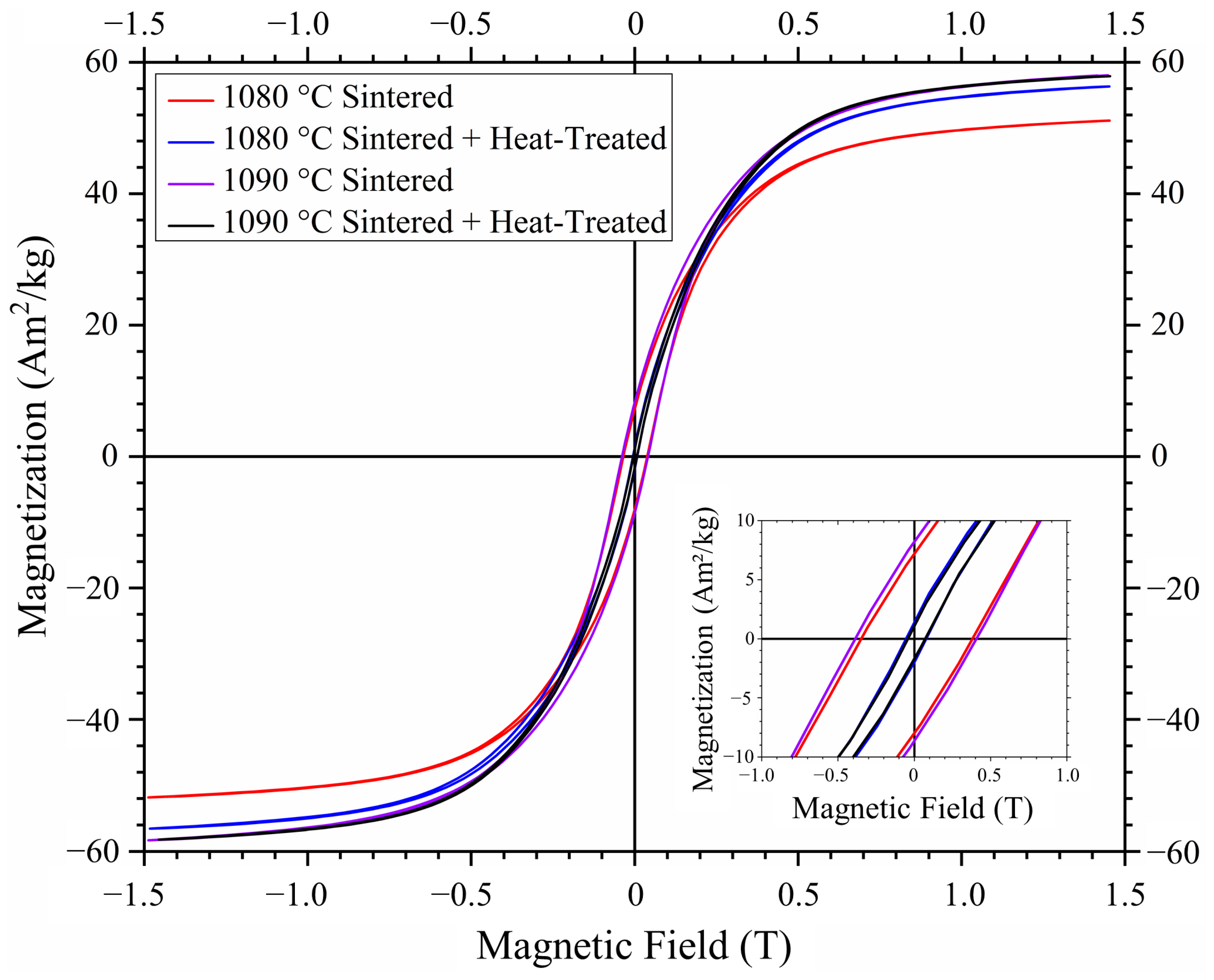
Saturation magnetization per unit weight (Msat in Table 1) is the observed magnetization at an applied field of 1.5 T (M–H curves in Figure 8). There is a minor increase in saturation magnetization in the 1080 °C sintered sample following heat treatment and nearly identical saturation magnetization in both 1090 °C sintered samples. Additionally, magnetic coercivity (determined using the calculation technique in [54]) approximately 40 mT is observed for the non-heat-treated samples, whereas the heat treatment in both the 1080 °C and 1090 °C sintering temperature cases tightens the hysteresis and reduces magnetic coercivity to approximately 10 mT. All values presented here are comparable to our previously published paper on identical non-heat-treated samples within the bounds of uncertainty [24]. Comparing values in both this and our previous study [24], it is determined that the saturation magnetization is largely indifferent to the heat-treatment step and the magnetic hysteresis tightening exhibited by heat-treated samples likely results from increased chemical ordering and homogenization (including integration of Mn from the grain boundaries to the grains) within the matrix.

4. Conclusions

The sintering of binder-jet 3D printed 14M Ni50Mn30Ga20 samples for 2 h at 1080 °C and 1090 °C, respectively, shows a large difference in grain size as identified by neutron diffraction area detector raw data inspection and quantitative stereology. This is accompanied by an increase in relative density (~80% to ~95%) through a 10 °C sintering temperature increase. This minor increase in sintering temperature accompanied a significant difference in mechanical properties, including an increase in hardness and reduced foam elastic moduli, and in transformation temperatures including a decrease in martensitic phase transformation onset. An additional heat-treatment step (annealing and ordering) was seen to only slightly affect the grain size, densification, and mechanical properties. However, heat treatment slightly homogenizes the sample following 1090 °C sintering, evident in the martensitic phase transformation onset temperature change versus the non-heat-treated sample. Magnetic anisotropy in differently sintered samples with twin variants finely spaced in the order of ≤10 μm in width suggests the possibility of MFIS in all presented sintering conditions. Magnetization curves suggested only slight saturation magnetization differences in the samples and hysteresis tightening, due in part to compositional homogenization. This study provided an avenue to identify the solid bulk elastic modulus utilizing equations from porous systems theory, as well as the elastic moduli for samples at respective processing conditions and sintering history. The transformation temperatures of Ni50Mn30Ga20 presented in this study provide the capability for further material composition and property tailoring through the introduction of heat-treatment steps and smart alloy design. Finally, by combining tailored composition, properties, grain and pore microstructure, binder-jet 3D printed polycrystalline Ni–Mn–Ga with low blocking stresses and, thus, a significant magnetic field-induced strain, may be achievable.

Supplementary Materials

The following supporting information can be downloaded at: https://www.mdpi.com/article/10.3390/met12050724/s1, Figure S1: SEM micrographs of the (a) 1080 °C sintered and (b) 1090 °C sintered only samples showing twinning, grain boundaries, and inherent porosity; Figure S2: Example grain boundary tracing for grain size determination; Figure S3: Exemplary SEM micrographs of nanoindentations of the 1080 °C sintered only sample (a) with and (b) without twin boundary build-up.

Author Contributions

Conceptualization: A.A. and M.C.; methodology: A.A., J.T. and A.M.; software: A.A., M.B. and R.C.W.; formal analysis: A.A., K.K. and M.C.; investigation: A.A., J.T., M.C., A.S., K.K., V.L. and A.M.; data curation: A.A., K.K., V.L., A.S., A.M., M.B. and R.C.W.; supervision: M.B., R.C.W., M.C. and K.U.; resources: M.C., K.U., M.B. and R.C.W.; writing—original draft preparation: A.A.; writing—review and editing: A.A., M.C., A.M., V.L., J.T., K.K., M.B., R.C.W., A.S. and K.U.; visualization: A.A., A.S. and K.K.; project administration: M.C.; funding acquisition: M.C. and K.U.; All authors have read and agreed to the published version of the manuscript.

Funding

This research was funded by the National Science Foundation (NSF), grant number 1727676, and the Academy of Finland, grant number 325910. J.T. and M.C. would like to acknowledge the Hewlett International Grant Program for travel funding.

Data Availability Statement

Please contact the corresponding investigator for the code utilized for characterization.

Acknowledgments

A.A. would like to acknowledge K. Shields and E. Stevens for DIC micrograph assistance, R. Rodriguez de Vecchis for sample preparation assistance, E. Stevens and J. Schneiderman for additional proofreading, and the Materials Metrology, Characterization, and Learning (MMCL) Lab at the University of Pittsburgh for the opportunity to perform characterization on the investigated samples.

Conflicts of Interest

The authors declare no conflict of interest. Additionally, the funders had no role in the design of the study; in the collection, analysis, or interpretation of data; in the writing of the manuscript, or in the decision to publish the results.

References

  1. Ullakko, K.; Huang, J.K.; Kantner, C.; O’Handley, R.C.; Kokorin, V.V. Large magnetic-field-induced strains in Ni2MnGa single crystals. Appl. Phys. Lett. 1996, 69, 1966–1968. [Google Scholar] [CrossRef]
  2. Ullakko, K. Magnetically controlled shape memory alloys: A new class of actuator materials. J. Mater. Eng. Perform. 1996, 5, 405–409. [Google Scholar] [CrossRef]
  3. Henry, C.P.; Bono, D.; Feuchtwanger, J.; Allen, S.M.; O’Handley, R.C. AC field-induced actuation of single crystal Ni–Mn–Ga. J. Appl. Phys. 2002, 91, 7810. [Google Scholar] [CrossRef]
  4. Toman, J.; Müllner, P.; Chmielus, M. Properties of as-deposited and heat-treated Ni-Mn-Ga magnetic shape memory alloy processed by directed energy deposition. J. Alloys Compd. 2018, 752, 455–463. [Google Scholar] [CrossRef] [Green Version]
  5. Müllner, P.; Chernenko, V.A.; Kostorz, G. Large cyclic magnetic-field-induced deformation in orthorhombic (14M) Ni–Mn–Ga martensite. J. Appl. Phys. 2004, 95, 1531–1536. [Google Scholar] [CrossRef]
  6. Tao, T.; Liang, Y.C. Bio-inspired Actuating System for Swimming Using Shape Memory Alloy Composites. Int. J. Autom. Comput. 2006, 3, 366–373. [Google Scholar] [CrossRef]
  7. Smith, A.R.; Tellinen, J.; Ullakko, K. Rapid actuation and response of Ni–Mn–Ga to magnetic-field-induced stress. Acta Mater. 2014, 80, 373–379. [Google Scholar] [CrossRef]
  8. Suorsa, I.; Pagounis, E.; Ullakko, K. Magnetic shape memory actuator performance. J. Magn. Magn. Mater. 2004, 272–276, 2029–2030. [Google Scholar] [CrossRef]
  9. Musiienko, D.; Saren, A.; Straka, L.; Vronka, M.; Kopeček, J.; Heczko, O.; Sozinov, A.; Ullakko, K. Ultrafast actuation of Ni-Mn-Ga micropillars by pulsed magnetic field. Scr. Mater. 2019, 162, 482–485. [Google Scholar] [CrossRef]
  10. Witherspoon, C.; Zheng, P.; Chmielus, M.; Dunand, D.C.; Müllner, P. Effect of porosity on the magneto-mechanical behavior of polycrystalline magnetic shape-memory Ni–Mn–Ga foams. Acta Mater. 2015, 92, 64–71. [Google Scholar] [CrossRef]
  11. Sozinov, A.; Likhachev, A.A.; Lanska, N.; Ullakko, K. Giant magnetic-field-induced strain in NiMnGa seven-layered martensitic phase. Appl. Phys. Lett. 2002, 80, 1746. [Google Scholar] [CrossRef]
  12. Roy, S.; Blackburn, E.; Valvidares, S.M.; Fitzsimmons, M.R.; Vogel, S.C.; Khan, M.; Dubenko, I.; Stadler, S.; Ali, N.; Sinha, S.K.; et al. Delocalization and hybridization enhance the magnetocaloric effect in Cu-doped Ni2MnGa. Phys. Rev. B 2009, 79, 235127. [Google Scholar] [CrossRef]
  13. Wilson, S.A.; Jourdain, R.P.J.; Zhang, Q.; Dorey, R.A.; Bowen, C.R.; Willander, M.; Wahab, Q.U.; Willander, M.; Al-hilli, S.M.; Nur, O.; et al. New materials for micro-scale sensors and actuators: An engineering review. Mater. Sci. Eng. R Rep. 2007, 56, 1–129. [Google Scholar] [CrossRef] [Green Version]
  14. Lázpita, P.; Rojo, G.; Gutiérrez, J.; Barandiaran, J.M.; O’Handley, R.C. Correlation between magnetization and deformation in a NiMnGa shape memory alloy polycrystalline ribbon. Sens. Lett. 2007, 5, 65–68. [Google Scholar] [CrossRef]
  15. Caputo, M.; Solomon, C.V.; Nguyen, P.-K.; Berkowitz, A.E. Electron Microscopy Investigation of Binder Saturation and Microstructural Defects in Functional Parts Made by Additive Manufacturing. Microsc. Microanal. 2016, 22, 1770–1771. [Google Scholar] [CrossRef] [Green Version]
  16. Ullakko, K.; Chmielus, M.; Müllner, P. Stabilizing a fine twin structure in Ni-Mn-Ga samples by coatings and ion implantation. Scr. Mater. 2015, 94, 40–43. [Google Scholar] [CrossRef] [Green Version]
  17. Chmielus, M.; Witherspoon, C.; Ullakko, K.; Müllner, P.; Schneider, R. Effects of Surface Damage on Twinning Stress and the Stability of Twin Microstructures of Magnetic Shape Memory Alloys. Acta Mater. 2011, 59, 2948–2956. [Google Scholar] [CrossRef]
  18. Chmielus, M.; Glavatskyy, I.; Hoffmann, J.U.; Chernenko, V.A.; Schneider, R.; Müllner, P. Influence of Constraints and Twinning Stress on Magnetic Field-Induced Strain of Magnetic Shape-Memory Alloys. Scr. Mater. 2011, 64, 888–891. [Google Scholar] [CrossRef]
  19. Caputo, M.P.; Solomon, C.V. A Facile Method for Producing Porous Parts with Complex Geometries from Ferromagnetic Ni-Mn-Ga Shape Memory Alloys. Mater. Lett. 2017, 200, 87–89. [Google Scholar] [CrossRef]
  20. Boonyongmaneerat, Y.; Chmielus, M.; Dunand, D.C.; Müllner, P. Increasing Magnetoplasticity in Polycrystalline Ni-Mn-Ga by Reducing Internal Constraints through Porosity. Phys. Rev. Lett. 2007, 99, 247201. [Google Scholar] [CrossRef]
  21. Chmielus, M.; Zhang, X.X.; Witherspoon, C.; Dunand, D.C.; Müllner, P. Giant Magnetic-Field-Induced Strains in Polycrystalline Ni–Mn–Ga Foams. Nat. Mater. 2009, 8, 863–866. [Google Scholar] [CrossRef] [PubMed]
  22. Lu, K.; Reynolds, W.T. 3DP Process for Fine Mesh Structure Printing. Powder Technol. 2008, 187, 11–18. [Google Scholar] [CrossRef]
  23. Taylor, S.L.; Shah, R.N.; Dunand, D.C. Ni-Mn-Ga Micro-Trusses via Sintering of 3D-Printed Inks Containing Elemental Powders. Acta Mater. 2018, 143, 20–29. [Google Scholar] [CrossRef]
  24. Mostafaei, A.; Rodriguez De Vecchis, P.; Stevens, E.L.; Chmielus, M. Sintering Regimes and Resulting Microstructure and Properties of Binder Jet 3D Printed Ni-Mn-Ga Magnetic Shape Memory Alloys. Acta Mater. 2018, 154, 355–364. [Google Scholar] [CrossRef]
  25. Mostafaei, A.; Kimes, K.A.; Stevens, E.L.; Toman, J.; Krimer, Y.L.; Ullakko, K.; Chmielus, M. Microstructural Evolution and Magnetic Properties of Binder Jet Additive Manufactured Ni-Mn-Ga Magnetic Shape Memory Alloy Foam. Acta Mater. 2017, 131, 482–490. [Google Scholar] [CrossRef] [Green Version]
  26. Caputo, M.P.; Berkowitz, A.E.; Armstrong, A.; Müllner, P.; Solomon, C.V. 4D Printing of Net Shape Parts Made from Ni-Mn-Ga Magnetic Shape-Memory Alloys. Addit. Manuf. 2018, 21, 579–588. [Google Scholar] [CrossRef]
  27. Mostafaei, A.; Elliott, A.M.; Barnes, J.E.; Li, F.; Tan, W.; Cramer, C.L.; Nandwana, P.; Chmielus, M. Binder jet 3D printing—Process parameters, materials, properties, modeling, and challenges. Prog. Mater. Sci. 2021, 119, 100707. [Google Scholar] [CrossRef]
  28. Wimpory, R.C.; Mikula, P.; Šaroun, J.; Poeste, T.; Li, J.; Hofmann, M.; Schneider, R. Efficiency Boost of the Materials Science Diffractometer E3 at BENSC: One Order of Magnitude Due to a Horizontally and Vertically Focusing Monochromator. Neutron News 2008, 19, 16–19. [Google Scholar] [CrossRef]
  29. Chmielus, M.; Witherspoon, C.; Wimpory, R.C.; Paulke, A.; Hilger, A.; Zhang, X.; Dunand, D.C.; Müllner, P. Magnetic-Field-Induced Recovery Strain in Polycrystalline Ni–Mn–Ga Foam. J. Appl. Phys. 2010, 108, 123526. [Google Scholar] [CrossRef] [Green Version]
  30. Rueden, C.T.; Schindelin, J.; Hiner, M.C.; DeZonia, B.E.; Walter, A.E.; Arena, E.T.; Eliceiri, K.W. ImageJ2: ImageJ for the next Generation of Scientific Image Data. BMC Bioinform. 2017, 18, 529. [Google Scholar] [CrossRef]
  31. Schindelin, J.; Arganda-Carreras, I.; Frise, E.; Kaynig, V.; Longair, M.; Pietzsch, T.; Preibisch, S.; Rueden, C.; Saalfeld, S.; Schmid, B.; et al. Fiji: An Open-Source Platform for Biological-Image Analysis. Nat. Methods 2012, 9, 676–682. [Google Scholar] [CrossRef] [PubMed] [Green Version]
  32. Mostafaei, A.; Rodriguez De Vecchis, P.; Nettleship, I.; Chmielus, M. Effect of Powder Size Distribution on Densification and Microstructural Evolution of Binder-Jet 3D-Printed Alloy 625. Mater. Des. 2019, 162, 375–383. [Google Scholar] [CrossRef]
  33. McIntyre, G.J. Area Detectors in Single-Crystal Neutron Diffraction. J. Phys. D Appl. Phys. 2015, 48, 504002. [Google Scholar] [CrossRef]
  34. Overholser, R.W.; Wuttig, M.; Neumann, D.A. Chemical Ordering in Ni-Mn-Ga Heusler Alloys. Scr. Mater. 1999, 40, 1095–1102. [Google Scholar] [CrossRef]
  35. Gibson, L.J.; Ashby, M.F. Cellular Solids: Structure and Properties, 2nd ed.; Cambridge University Press: Cambridge, UK, 1999. [Google Scholar]
  36. Chicot, D.; N’Jock, M.Y.; Roudet, F.; Decoopman, X.; Staia, M.H.; Puchi-Cabrera, E.S. Some Improvements for Determining the Hardness of Homogeneous Materials from the Work-of-Indentation. Int. J. Mech. Sci. 2016, 105, 279–290. [Google Scholar] [CrossRef]
  37. Chen, Z.; Wang, X.; Bhakhri, V.; Giuliani, F.; Atkinson, A. Nanoindentation of Porous Bulk and Thin Films of La0.6Sr0.4Co0.2Fe0.8O3−δ. Acta Mater. 2013, 61, 5720–5734. [Google Scholar] [CrossRef] [Green Version]
  38. Kohl, M.; Agarwal, A.; Chernenko, V.A.; Ohtsuka, M.; Seemann, K. Shape Memory Effect and Magnetostriction in Polycrystalline Ni–Mn–Ga Thin Film Microactuators. Mater. Sci. Eng. A 2006, 438–440, 940–943. [Google Scholar] [CrossRef]
  39. Zorzi, J.E.; Perottoni, C.A. Estimating Young’s Modulus and Poisson’s Ratio by Instrumented Indentation Test. Mater. Sci. Eng. A 2013, 574, 25–30. [Google Scholar] [CrossRef]
  40. Ozdemir Kart, S.; Cagın, T. Elastic Properties of Ni2MnGa from First-Principles Calculations. J. Alloys Compd. 2010, 508, 177–183. [Google Scholar] [CrossRef]
  41. Kustov, S.; Saren, A.; Sozinov, A.; Kaminskii, V.; Ullakko, K. Ultrahigh Damping and Young’s Modulus Softening Due to a/b Twins in 10M Ni-Mn-Ga Martensite. Scr. Mater. 2020, 178, 483–488. [Google Scholar] [CrossRef]
  42. Chmielus, M.; Rolfs, K.; Wimpory, R.; Reimers, W.; Müllner, P.; Schneider, R. Effects of Surface Roughness and Training on the Twinning Stress of Ni–Mn–Ga Single Crystals. Acta Mater. 2010, 58, 3952–3962. [Google Scholar] [CrossRef]
  43. Jayaraman, A.; Kiran, M.S.R.N.; Ramamurty, U. Mechanical Anisotropy in Austenitic NiMnGa Alloy: Nanoindentation Studies. Crystals 2017, 7, 254. [Google Scholar] [CrossRef] [Green Version]
  44. Kramer, D.; Huang, H.; Kriese, M.; Robach, J.; Nelson, J.; Wright, A.; Bahr, D.; Gerberich, W.W. Yield Strength Predictions from the Plastic Zone around Nanocontacts. Acta Mater. 1998, 47, 333–343. [Google Scholar] [CrossRef]
  45. Li, T.L.; Gao, Y.F.; Bei, H.; George, E.P. Indentation Schmid Factor and Orientation Dependence of Nanoindentation Pop-in Behavior of NiAl Single Crystals. J. Mech. Phys. Solids 2011, 59, 1147–1162. [Google Scholar] [CrossRef]
  46. Aaltio, I.; Liu, X.W.; Valden, M.; Lahtonen, K.; Söderberg, O.; Ge, Y.; Hannula, S.-P. Nanoscale Surface Properties of a Ni–Mn–Ga 10M Magnetic Shape Memory Alloy. J. Alloys Compd. 2013, 577, S367–S371. [Google Scholar] [CrossRef]
  47. Davis, P.H.; Efaw, C.M.; Patten, L.K.; Hollar, C.; Watson, C.S.; Knowlton, W.B.; Müllner, P. Localized Deformation in Ni-Mn-Ga Single Crystals. J. Appl. Phys. 2018, 123, 215102. [Google Scholar] [CrossRef]
  48. Tian, X.H.; Sui, J.H.; Zhang, X.; Zheng, X.H.; Cai, W. Grain Size Effect on Martensitic Transformation, Mechanical and Magnetic Properties of Ni–Mn–Ga Alloy Fabricated by Spark Plasma Sintering. J. Alloys Compd. 2012, 514, 210–213. [Google Scholar] [CrossRef]
  49. Qian, M.F.; Zhang, X.X.; Wei, L.S.; Geng, L.; Peng, H.X. Effect of Chemical Ordering Annealing on Martensitic Transformation and Superelasticity in Polycrystalline Ni–Mn–Ga Microwires. J. Alloys Compd. 2015, 645, 335–343. [Google Scholar] [CrossRef]
  50. Schlagel, D.; Wu, Y.; Zhang, W.; Lograsso, T. Chemical Segregation during Bulk Single Crystal Preparation of Ni–Mn–Ga Ferromagnetic Shape Memory Alloys. J. Alloys Compd. 2000, 312, 77–85. [Google Scholar] [CrossRef]
  51. Dunand, D.C.; Müllner, P. Size Effects on Magnetic Actuation in Ni-Mn-Ga Shape-Memory Alloys. Adv. Mater. 2011, 23, 216–232. [Google Scholar] [CrossRef]
  52. Laitinen, V.; Sozinov, A.; Saren, A.; Chmielus, M.; Ullakko, K. Characterization of As-Built and Heat-Treated Ni-Mn-Ga Magnetic Shape Memory Alloy Manufactured via Laser Powder Bed Fusion. Addit. Manuf. 2021, 39, 101854. [Google Scholar] [CrossRef]
  53. Laitinen, V.; Sozinov, A.; Saren, A.; Salminen, A.; Ullakko, K. Laser Powder Bed Fusion of Ni-Mn-Ga Magnetic Shape Memory Alloy. Addit. Manuf. 2019, 30, 100891. [Google Scholar] [CrossRef]
  54. Wang, H.; Zhang, H.; Wang, Y.; Tan, W.; Huo, D. Spin glass feature and exchange bias effect in metallic Pt/antiferromagnetic LaMnO3 heterostructure. J. Phys. Condens. Mat. 2021, 33, 285802. [Google Scholar] [CrossRef] [PubMed]
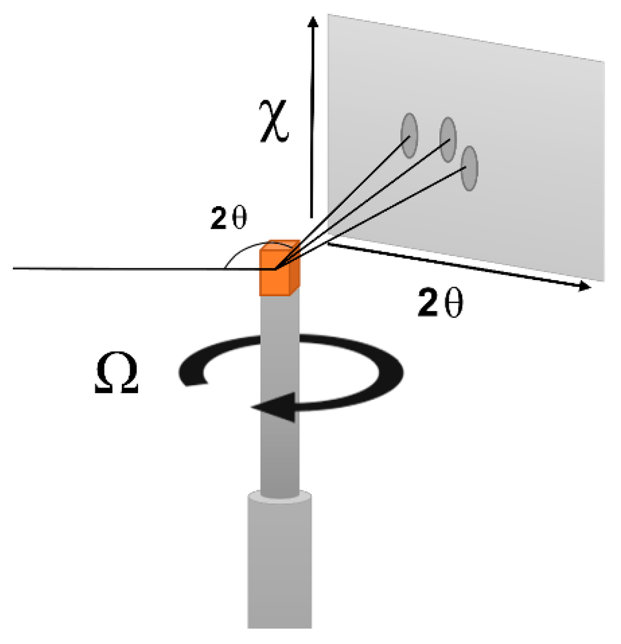
Figure 1. Schematic of the goniometer setup on Beamline E3 at HZB.
Metals 12 00724 g001
Figure 2. Neutron diffraction area detector image received from HZB before (a) and after (b) image processing. Exemplary clusters are marked using white arrows.
Metals 12 00724 g002
Figure 3. Processed and integrated area detector diffraction images (top) and individual example processed diffraction images taken at one Ω step (bottom) for each of the four samples. Images are taken of the (220) plane family of 14M Ni–Mn–Ga martensite. Insets of each diffraction image display the location of the integrated diffraction curve for each band. These diffraction angles were used to determine lattice parameters for each sample.
Metals 12 00724 g003
Figure 4. DIC micrographs of polished samples for the investigated materials during this study. The top row presents the 1080 °C sintered sample (a) and 1080 °C sintered + heat-treated sample (b), respectively, whereas the bottom row presents the 1090 °C sintered sample (c) and 1090 °C sintered + heat-treated sample (d).
Metals 12 00724 g004
Figure 5. Force–displacement curves extracted from nanoindentation tests on the 1080 °C and 1090 °C sintered and heat-treated samples to display exemplary pop-in observations (see arrows). Larger deformation in the 1080 °C sintered + heat-treated sample corresponds to the smaller hardness value observed between the two samples.
Metals 12 00724 g005
Figure 6. DSC curves presenting the transformation temperatures of the four investigated samples. Tangent lines at transformation onsets and ticks at peak maxima are presented to aid the eye. Curie temperature was determined at heat flow stepwise increase at ~90 °C. See Table 1 for observed transformation temperatures.
Metals 12 00724 g006
Figure 7. Optical micrographs (left) and corresponding AFM (middle)/MFM (right) scans of the red squares of the left micrographs for the 1080 °C (row (a)) and 1090 °C (row (b)) sintered samples at twin-dense regions. The square red regions are 20 µm × 20 µm as indicated in the AFM/MFM micrographs.
Metals 12 00724 g007
Figure 8. Magnetization (M–H) curves comparing saturation magnetization and coercivity for the different sintering and post-processing conditions. Inset is a magnified view of the hysteresis (note the unit change on the horizontal axis).
Metals 12 00724 g008
Table 1. Crystallographic, mechanical, physical, and phase transformation properties of the Ni–Mn–Ga binder jetted samples.
Parameter1080 °C Sintered1080 °C Sintered and
Annealed
1090 °C Sintered1090 °C Sintered and
Annealed
a (Å)6.169 ± 0.0046.169 ± 0.0056.190 ± 0.0056.177 ± 0.018
b (Å)5.822 ± 0.0035.833 ± 0.0045.820 ± 0.0035.823 ± 0.016
c (Å)5.531 ± >0.0015.530 ± >0.0015.526 ± 0.0015.530 ± >0.001
c/a0.89650.89580.89420.8958
Unit Cell Volume (Å3)198.6 ± 0.2198.9 ± 0.3199.0 ± 0.5198.9 ± 1.1
Hardness (GPa)3.00 ± 0.243.36 ± 0.373.47 ± 0.243.49 ± 0.22
Reduced Elastic Modulus (GPa)92.6 ± 7.388.3 ± 13.7104.9 ± 12.2108.5 ± 7.0
Relative Density (%)79.4 ± 5.680.1 ± 2.094.2 ± 2.394.6 ± 3.5
Foam Elastic
Modulus (GPa)
91.7 ± 7.9787.1 ± 14.7105 ± 13.8109 ± 7.90
Projected Bulk
Elastic Modulus (GPa)
147 ± 11.7136 ± 23.0119 ± 15.6123 ± 8.98
Grain Diameter (μm)43.6 ± 1.948.9 ± 2.982.4 ± 2.691.6 ± 2.4
AS (°C)84.582.475.680.0
AF (°C)91.291.382.589.9
AP (°C)89.089.279.386.3
MS (°C)86.787.277.182.0
MF (°C)78.875.768.770.2
MP (°C)83.583.272.477.4
Ttrans (°C)86.386.275.981.9
TC (°C)88888887
Msat (Am2/kg)52.456.458.057.9
Publisher’s Note: MDPI stays neutral with regard to jurisdictional claims in published maps and institutional affiliations.