
Experimental Investigations of Expansion Strength of Hydraulic Expansion Joints Interconnecting Tube and Fins Heat Exchanger

Abstract
1. Introduction
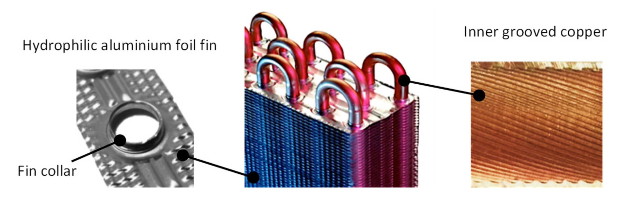
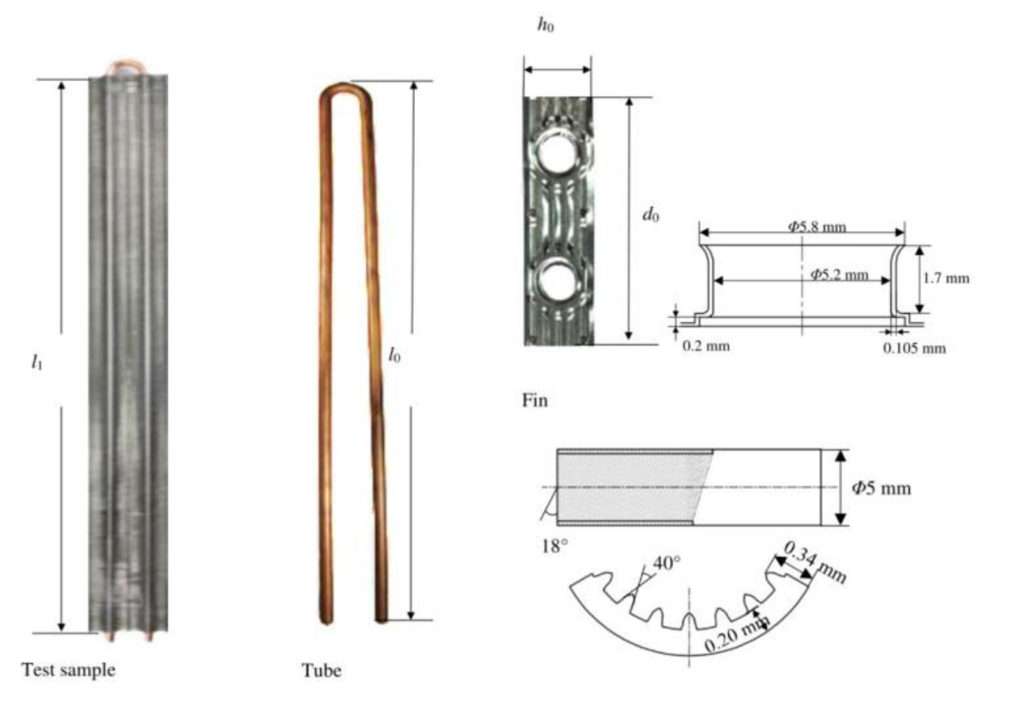
2. Geometries of Tubes and Fins
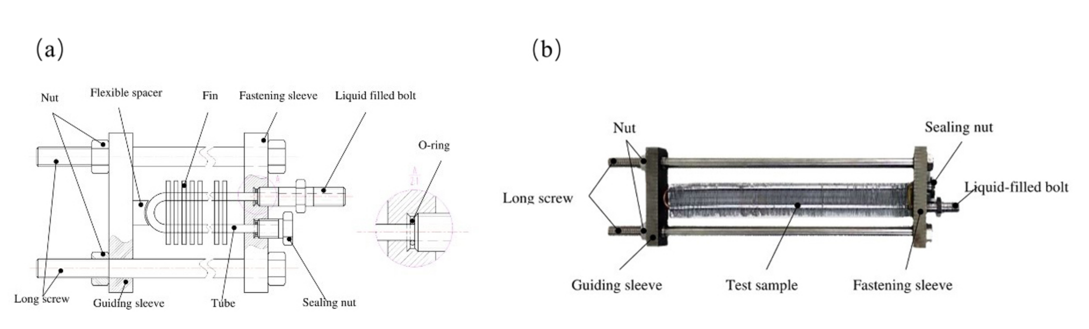
3. Design of the Hydraulic Expansion Device
- (1)
- Hydraulic pressure generator: This is a liquid-filled bolt connected to an external pressure liquid supply system. The liquid-filled bolt has a through-hole in the middle. One end of the bolt is connected to the liquid supply apparatus, and the other end is connected to the heat exchange tube.
- (2)
- Liquid sealing system: Each end of the tube is connected to a fastening tube sleeve and sealing nut. The tube sleeve has two threaded holes to connect the sealing nut and liquid-filled bolt. To ensure the sealing performance, both ends of the tube are connected with the liquid-filled bolt, and the sealing nut has an O-ring to prevent liquid leakage when the device is hydraulically expanded. The O-rings act together with the threaded hole in the tube sleeve to form a tightening seal with the sealing nut and liquid-filled bolt.
- (3)
- Test sample location: This part comprises two long screws, a fastening tube sleeve, and a guiding sleeve. Both sleeves have through-holes to allow the long screw to pass through, and the nut is tightened to support the device. A flexible cushion block is between the guiding sleeve and end of the tube to protect the tube during hydraulic expansion. To ensure the applicability and flexibility of the device, the guiding sleeve and fastening sleeve were designed with the same external dimensions and volume. The two ends of the sleeves have through-holes for the long screw to pass through to cooperate with the nut. Hence, the device can adapt to different lengths of tubes and numbers of fins.
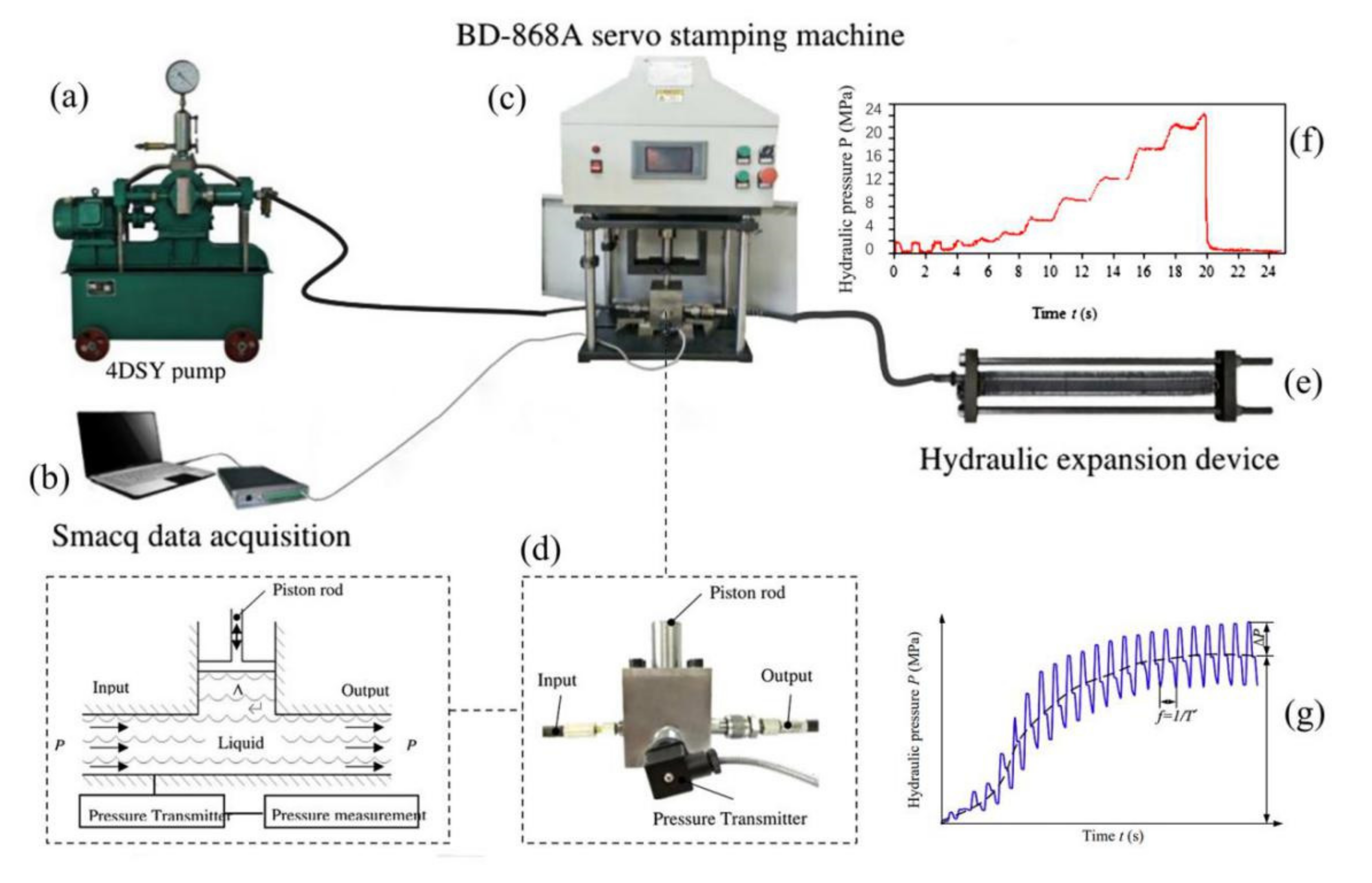
4. Experiments
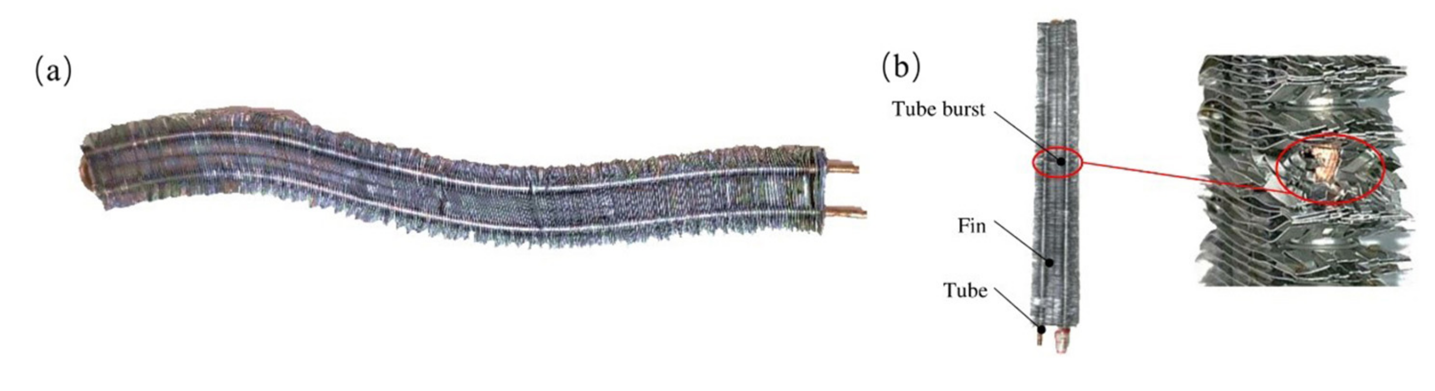
4.1. Non-Pulsating Hydraulic Expansion
4.2. Pulsating Hydraulic Expansion
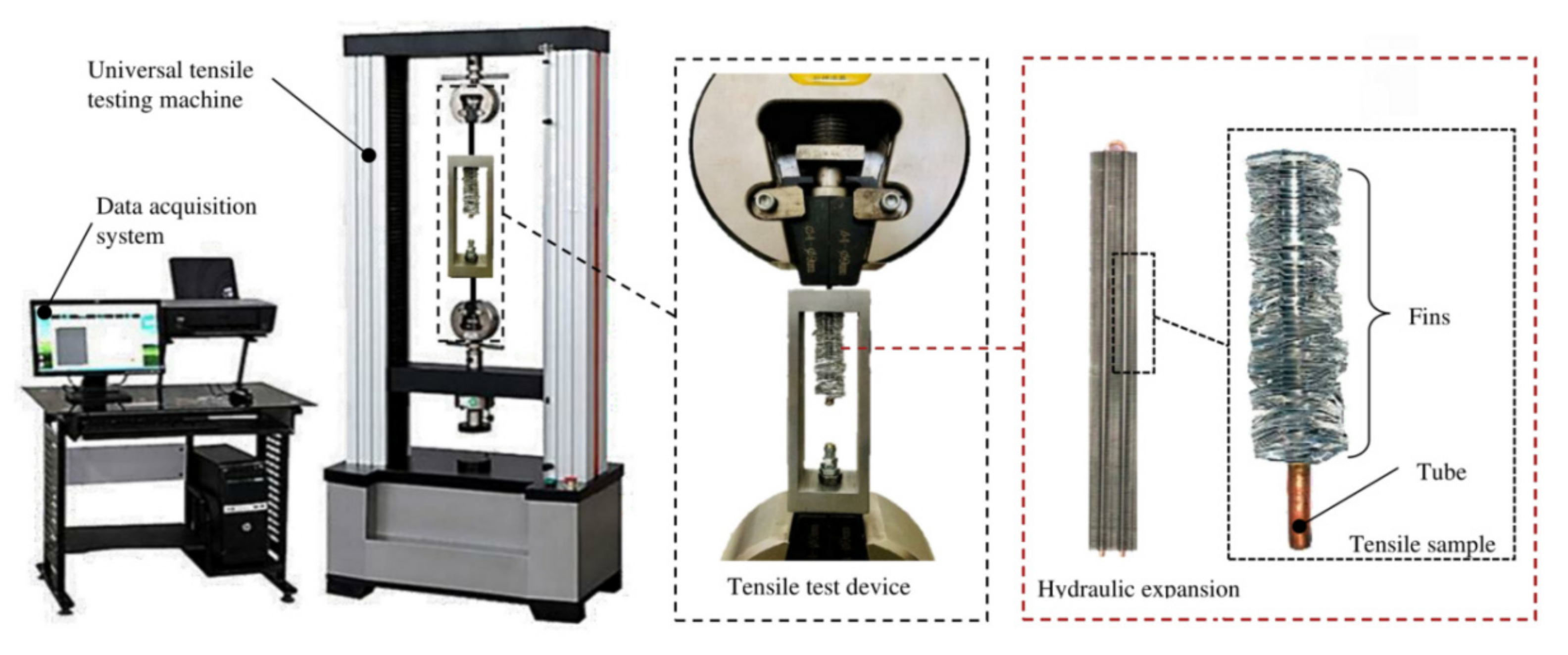
4.3. Tensile Tests
5. Results and Discussion
5.1. Proper Hydraulic Pressure Range
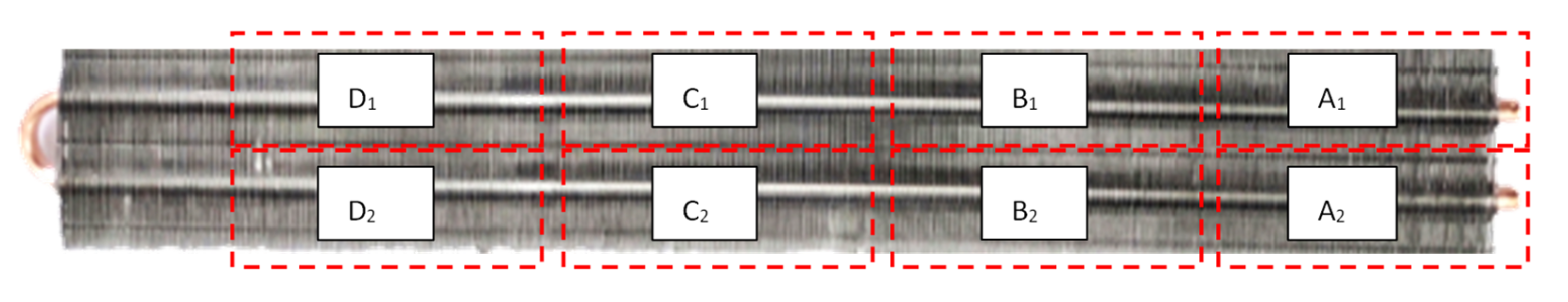
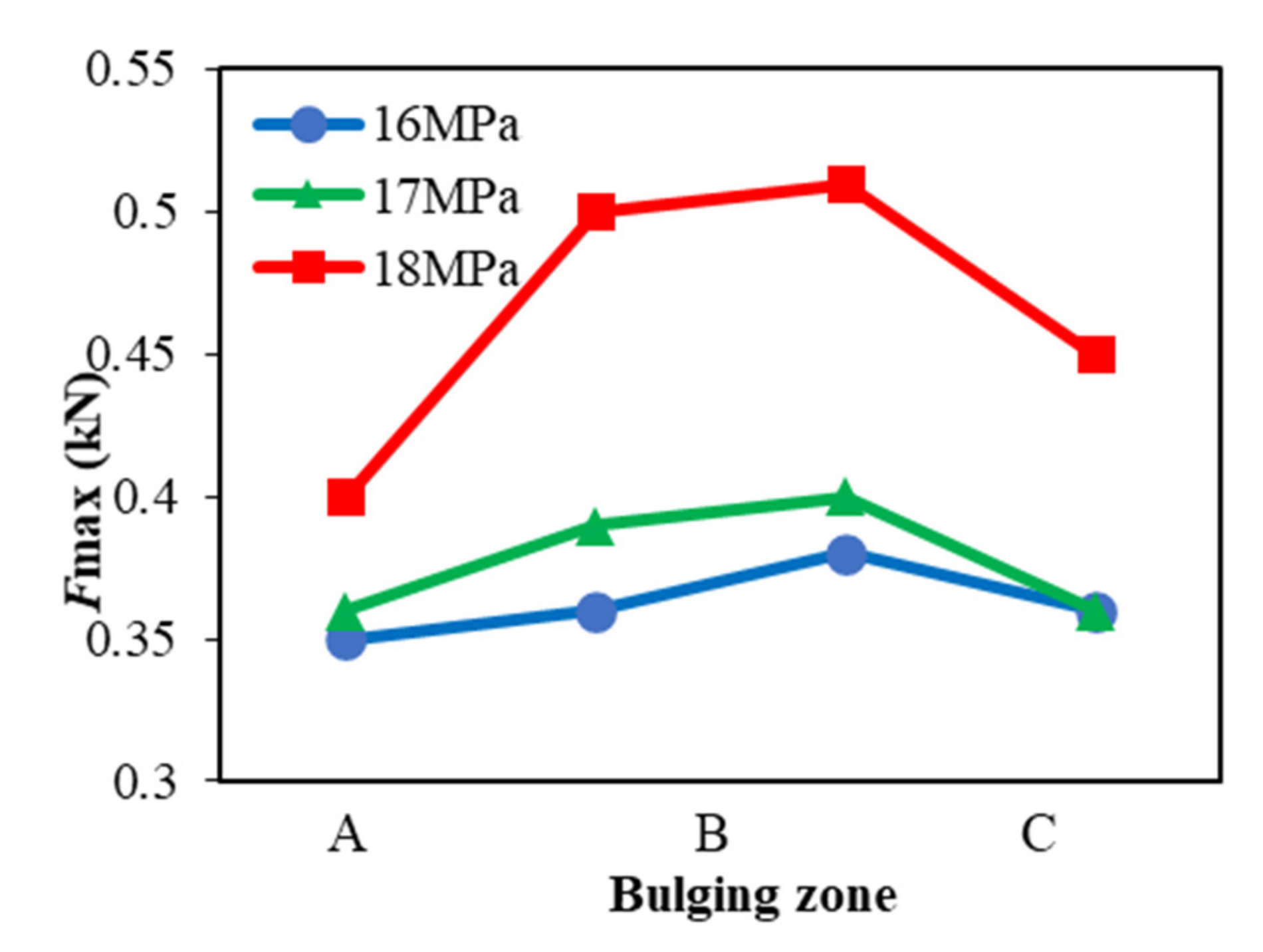
5.2. Pull-Out Forces in the Bulging Zones
5.3. Effect of Pulsation Parameters on the Pull-Out Force
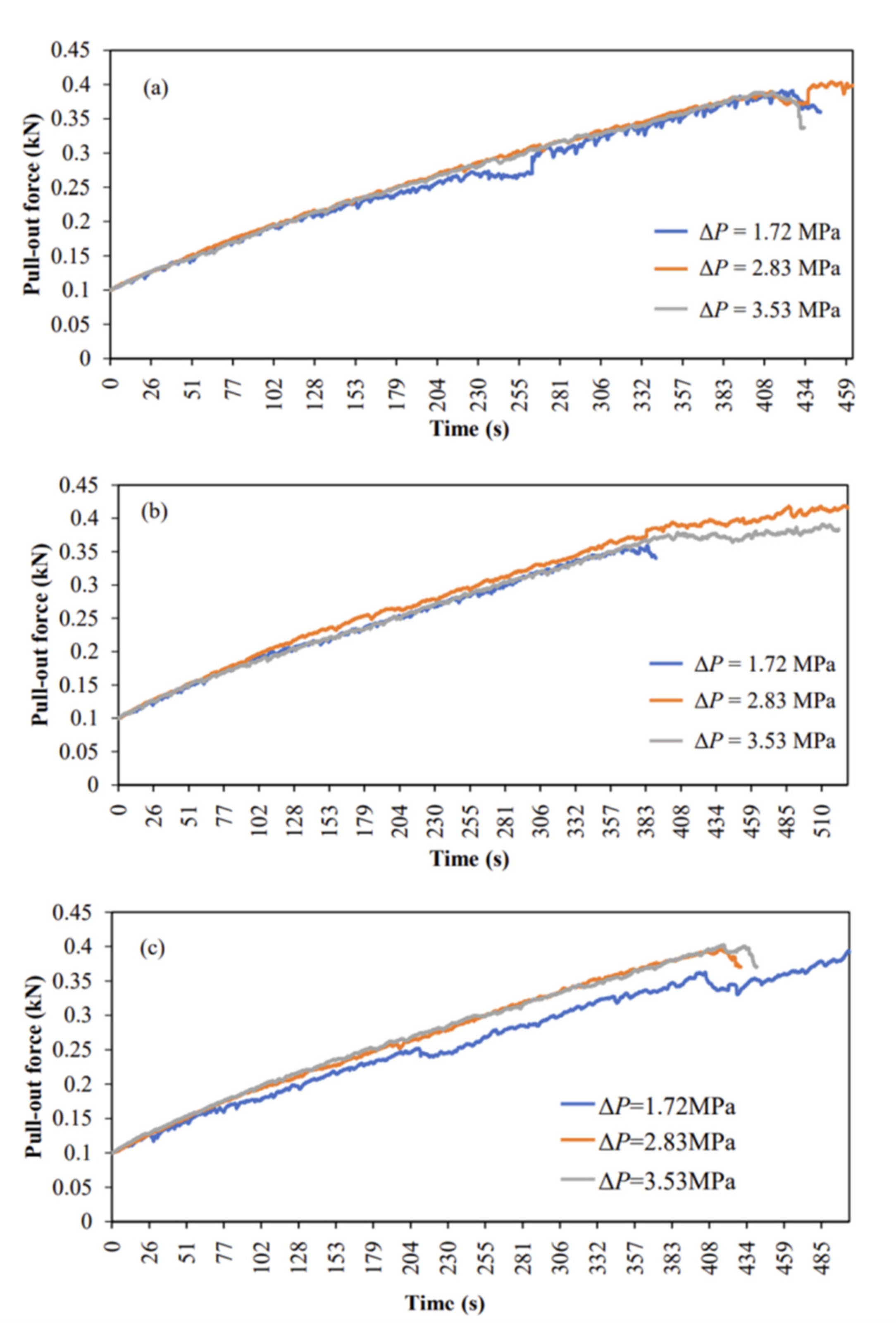
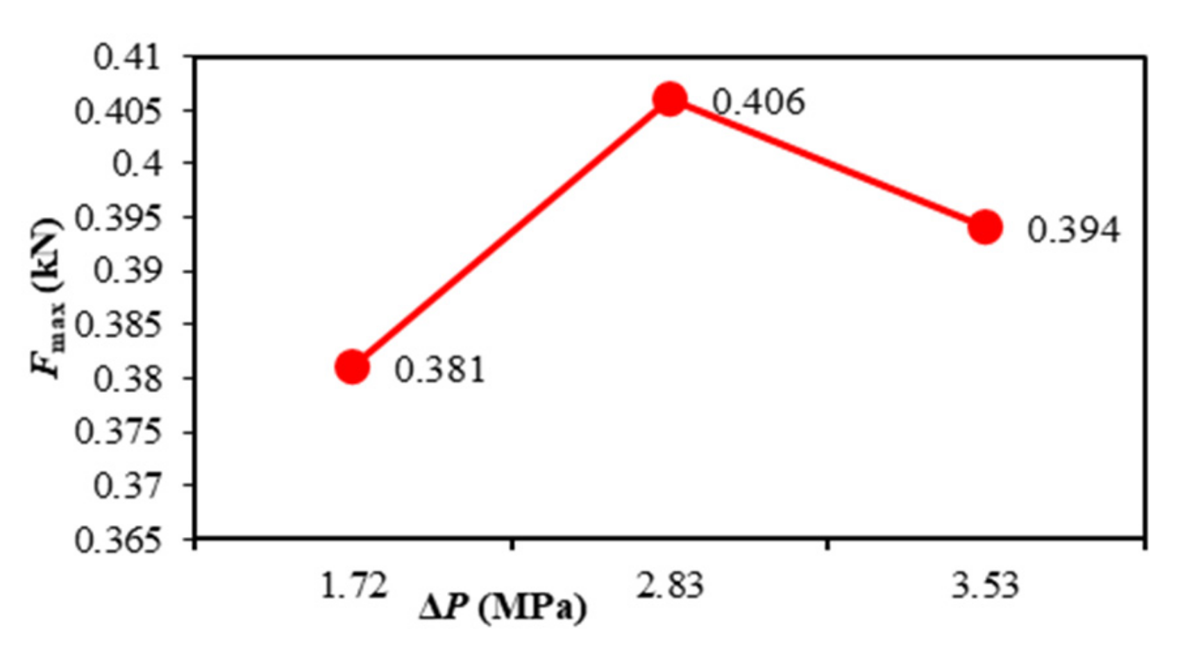
5.3.1. Pulsation Amplitude
5.3.2. Pulsation Frequency
6. Conclusions
- (1)
- In the proper hydraulic expansion range of 16–18 MPa, Fmax was 0.47 kN at a Pmax of 18 MPa. Thus, the proper hydraulic expansion pressure of the test samples was determined to be 18 MPa.
- (2)
- The middle section of the test sample could withstand a higher pull-out force than the other sections, which provided better reliability in the hydraulic expansion tests.
- (3)
- When ΔP ≤ 2.83 MPa, the pull-out force increased with the amplitude; when ΔP > 2.83 MPa, the pull-out force decreased with increasing amplitude. At ΔP = 2.83 MPa, the maximum pull-out force peaked at 0.406 kN.
- (4)
- When the amplitude was fixed, increasing the frequency increased the uniformity of the joint between the tube and fin, which improved the reliability of the joint.
Author Contributions
Funding
Institutional Review Board Statement
Informed Consent Statement
Data Availability Statement
Conflicts of Interest
References
- Kaji, R.; Yoshioka, S.; Fujino, H. The Effect of Inner Grooved Tubes on the Heat Transfer Performance of Air-cooled Heat Exchangers of CO2 Heat Pump System. In Proceedings of the International Refrigeration and Air Conditioning Conference, Purdue University, West Lafayette, IN, USA, 16–19 July 2012. [Google Scholar]
- Al-Shamani, A.N.; Sopian, K.; Mohammed, H.A.; Mat, S.; Ruslan, M.H.; Abed, A.M. Enhancement Heat Transfer Characteristics in the Channel with Trapezoidal Rib-groove Using Nanofluids. Case Stud. Therm. Eng. 2015, 5, 48–58. [Google Scholar] [CrossRef]
- Rahman, M.M.; Zhen, T.; Kadir, A.K. Numerical Simulation of Fluid Flow and Heat Transfer in Enhanced Copper Tube. In Proceedings of the IOP Conference Series: Earth and Environmental, Putrajaya, Malaysia, 5–6 March 2013. [Google Scholar]
- Maneewan, S.; Tipsaenprom, W.; Lertsatitthanakorn, C. Thermal Comfort Study of a Compact Thermoelectric Air Conditioner. J. Electron. Mater. 2010, 39, 1659–1664. [Google Scholar] [CrossRef]
- Cox, T.L.; Patel, R.L. Small Diameter in Line Tube and Fin Aluminum Heat Exchanger for Automotive Air Conditioning Sys-tems. In Proceedings of the Sae International Congress & Exposition, Warrendale, PA, USA, 27 February 1989. [Google Scholar]
- Ding, G.; Wu, G.; Liu, T. Development of Heat Exchanger for Refrigeration and Air-Conditioning–Fin-and-tube Heat Ex-changers Using Small Diameter Tubes. J. Appl. Sci. Technol. 2019, 4, 40–45. [Google Scholar]
- Yang, L.; Zhao, Q. Forming Limit Diagrams for Tubes with Non-uniform Thickness in Hydro-bulging. Int. J. Adv. Manuf. Technol. 2019, 103, 901–911. [Google Scholar] [CrossRef]
- Yokell, S. Expanded, and Welded-and-Expanded Tube-to-Tubesheet Joints. J. Press. Vessel Technol. 1992, 114, 157–165. [Google Scholar] [CrossRef][Green Version]
- Rikimaru, T.; Ito, M. Hammering Hydroforming of Tubes. Press Work. 2001, 39, 58–65. [Google Scholar]
- di Lorenzo, R.; Filice, L.; Umbrello, D.; Micari, F.; Ghosh, S.; Castro, J.C.; Lee, J.K. An Integrated Approach to the Design of Tube Hydroforming Processes: Artificial Intelligence, Numerical Analysis and Experimental Investigation. AIP Conf. Proc. 2004, 712, 1118–1123. [Google Scholar]
- Khalili, K.; Ahmadi-Brooghani, S.Y.; Ashrafi, A. Investigation on the Effect of Pulsating Pressure on Tube-Hydroforming Process. Key Eng. Mater. 2011, 473, 618–623. [Google Scholar] [CrossRef]
- Loh-Mousavi, M.; Mirhosseini, A.M.; Amirian, G. Investigation of Modified Bi-Layered Tube Hydroforming by Pulsating Pressure. Key Eng. Mater. 2011, 486, 5–8. [Google Scholar] [CrossRef]
- Yang, L.F.; Chen, F.J. Investigation on the Formability of a Tube in Pulsating Hydroforming. Mater. Sci. Forum 2009, 628–629, 617–622. [Google Scholar] [CrossRef]
- Mohamed, M.; El-Aty, A.A.; Abdel Aziz, H.; Nader, F. Theoretical Investigations and Simulation of the Hydroforming Processes Performed on c1010 Low Carbon Steel Tubes. Appl. Mech. Mater. 2015, 799–800, 443–447. [Google Scholar] [CrossRef]
- Yang, Y.; Fan, L.; Xu, C.; Dong, X. Experimental Study of Mechanical Properties of 30SiMn2MoVA Steel Gun Barrel Processed by Cold Radial Forging. ASME J. Press. Vessel Technol. 2020, 143, 011501. [Google Scholar] [CrossRef]
- Zheng, M.; Gao, H.; Teng, H.; Hu, J.; TIian, Z.; Zhao, Y. A Simplified Approach for the Hydro-forming Process of Bi-metallic Composite Pipe. Arch. Metall. Mater. 2017, 62, 879–883. [Google Scholar] [CrossRef][Green Version]
- Merah, N.; Al-Zayer, A.; Shuaib, A.; Arif, A. Finite Element Evaluation of Clearance Effect on Tube-to-tubesheet Joint Strength. Int. J. Press. Vessel. Pip. 2003, 80, 879–885. [Google Scholar] [CrossRef]
- Guan, Y.; Pourboghrat, F.; Barlat, F. Finite Element Modeling of Tube Hydroforming of Polycrystalline Aluminum Alloy Extrusions. Int. J. Plast. 2006, 22, 2366–2393. [Google Scholar] [CrossRef]
- Wang, J.P.; Jin, W.Y.; Wang, X.M.; Gao, Z.L. Study on Pull-out Force in Tube-and-shell Heat Exchangers with Finite Element Method. Nucl. Power Eng. 2008, 29, 58–61. [Google Scholar]
- Ma, J.; Yang, L.; He, Y. Dynamic Frictional Characteristics of TP2 Copper Tubes during Hydroforming under Different Loading and Fluid Velocities. J. Mater. Eng. Perform. 2019, 28, 3661–3672. [Google Scholar] [CrossRef]
- Sadlowska, H.; Morawinsk, L.; Jasinski, C. Strain Measurement in Free Tube Hydroforming Process. Arch. Metall. Mater. 2020, 65, 257–263. [Google Scholar]
- Zhu, H.H.; He, Z.B.; Lin, Y.L.; Zheng, K.L.; Fan, X.B.; Yuan, S.J. The Development of a Novel Forming Limit Diagram under Nonlinear Loading Paths in Tube Hydroforming. Int. J. Mech. Sci. 2020, 172, 105392. [Google Scholar] [CrossRef]
- Guo, T.Y.; Fahrettin, O.; Firas, J.; Jamal, Y.S.A. Analysis of Contact Pressure of Mechanically Lined Corrosion Resistant Alloy Pipe by Hydraulic Expansion Process. ASME J. Press. Vessel. Technol. 2017, 139, 021212. [Google Scholar] [CrossRef]


| Tube | Value | Fin | Value |
|---|---|---|---|
| Outer diameter Φ0 (mm) | 5 | Arrangement length l1 (mm) | 355 |
| Wall thickness δ (mm) | 0.5 | Width d0 (mm) | 40 |
| Length l0 (mm) | 375 | Height h0 (mm) | 11 |
| Density (g·cm−3) | 8.916 | Density (g·cm−3) | 2.780 |
| Young’s modulus (GPa) | 127 | Young’s modulus (GPa) | 68 |
| Poisson’s ratio | 0.33 | Poisson’s ratio | 0.33 |
| Tensile stress (MPa) | 205.807 | Tensile stress (MPa) | 136.889 |
| Yield stress (MPa) | 66 | Yield stress (MPa) | 132 |
| Stroke s (mm) | Speed n (r/min) | Amplitude ΔP (MPa) | Frequency f (c/s) |
|---|---|---|---|
| 2 | 200 | 1.72 | 0.67 |
| 4 | 500 | 2.83 | 1.29 |
| 6 | 800 | 3.53 | 1.8 |
| Stroke s (mm) | Speed n (r/min) | Amplitude ΔP (MPa) | Frequency f (c/s) |
|---|---|---|---|
| 2 | 200 | 1.72 | 0.67 |
| 2 | 500 | 1.72 | 1.29 |
| 2 | 800 | 1.72 | 1.80 |
| 4 | 200 | 2.83 | 0.67 |
| 4 | 500 | 2.83 | 1.29 |
| 4 | 800 | 2.83 | 1.80 |
| 6 | 200 | 3.53 | 0.67 |
| 6 | 500 | 3.53 | 1.29 |
| 6 | 800 | 3.53 | 1.80 |
| Pmax (MPa) | Fmax (kN) |
|---|---|
| 16 | 0.36 |
| 17 | 0.38 |
| 18 | 0.47 |
| Pmax (MPa) | Fmax (kN) | |||
|---|---|---|---|---|
| A | B | C | D | |
| 16 | 0.35 | 0.36 | 0.38 | 0.36 |
| 17 | 0.36 | 0.39 | 0.40 | 0.36 |
| 18 | 0.40 | 0.50 | 0.51 | 0.45 |
| ΔP (MPa) | f (c/s) | Fmax (kN) |
|---|---|---|
| 1.72 | 0.67 | 0.391 |
| 1.72 | 1.29 | 0.394 |
| 1.72 | 1.80 | 0.359 |
| 2.83 | 0.67 | 0.404 |
| 2.83 | 1.29 | 0.396 |
| 2.83 | 1.80 | 0.419 |
| 3.53 | 0.67 | 0.389 |
| 3.53 | 1.29 | 0.403 |
| 3.53 | 1.80 | 0.391 |
Publisher’s Note: MDPI stays neutral with regard to jurisdictional claims in published maps and institutional affiliations. |
© 2022 by the authors. Licensee MDPI, Basel, Switzerland. This article is an open access article distributed under the terms and conditions of the Creative Commons Attribution (CC BY) license (https://creativecommons.org/licenses/by/4.0/).
Share and Cite
Han, H.; Yang, L.; Jiang, J.; Ma, J. Experimental Investigations of Expansion Strength of Hydraulic Expansion Joints Interconnecting Tube and Fins Heat Exchanger. Metals 2022, 12, 641. https://doi.org/10.3390/met12040641
Han H, Yang L, Jiang J, Ma J. Experimental Investigations of Expansion Strength of Hydraulic Expansion Joints Interconnecting Tube and Fins Heat Exchanger. Metals. 2022; 12(4):641. https://doi.org/10.3390/met12040641
Chicago/Turabian StyleHan, Haimei, Lianfa Yang, Jingyu Jiang, and Jianping Ma. 2022. "Experimental Investigations of Expansion Strength of Hydraulic Expansion Joints Interconnecting Tube and Fins Heat Exchanger" Metals 12, no. 4: 641. https://doi.org/10.3390/met12040641
APA StyleHan, H., Yang, L., Jiang, J., & Ma, J. (2022). Experimental Investigations of Expansion Strength of Hydraulic Expansion Joints Interconnecting Tube and Fins Heat Exchanger. Metals, 12(4), 641. https://doi.org/10.3390/met12040641