Abstract
The work hardening behaviour of GCr15 bearing steel during rolling contact fatigue (RCF) is investigated. Ball-on-rod RCF tests and micro-indentation tests are performed to obtain various subsurface hardness profiles in rod specimens. It is found that orthogonal shear stress is responsible for work hardening under Hertzian contact and that the extent of hardness increase is positively associated with the stress level and number of cycles. A dislocation-based work hardening model is established by combining the Kocks–Mecking theory, the bearing steel plasticity equation and the Taylor relation. The proposed model is capable of predicting hardness changes with any given rolling contact stress state and number of cycles. The modelling results are compared against the experimental results, with good agreement obtained. This research also provides a methodology for studying the work hardening of different types of bearing steels undergoing RCF, from experiment to modelling.
1. Introduction
Bearings made of high-strength steels are exposed to severe service conditions such as high contact pressure, a high rotational speed, a high number of cycles and an elevated temperature. Therefore, bearing steels are prone to rolling contact fatigue (RCF) [1]. Due to the unique stress state under rolling contact [2], RCF becomes rather complex, and the material exhibits numerous changes in its microstructure and mechanical properties [3]. Amongst these changes, work hardening is widely reported in both through hardened and case hardened bearing steels under rolling contact [4,5] and is believed to be crucial for the formation of cracks and microstructural alterations, which determine the RCF life [6]. However, given the complex stress state under rolling contact, work hardening takes place at the subsurface, the extent of which varies with depth. Therefore, an accurate description of the subsurface stress state becomes necessary for studying work hardening under rolling contact.
Due to the high cost of full-scale bearing testing, simplified RCF testing methods with various contact geometries were widely used to study the RCF of bearing steels. The two most representative RCF testing methods in the literature are ball-on-rod testing and flat-washer testing [7], with the former simulating the rolling contact mode of deep groove ball bearings and the latter simulating the rolling contact mode of thrust bearings. Except for contact geometry, the work hardening of tested material can also be influenced by testing conditions, such as contact load, temperature and number of cycles. Kang et al. [8] investigated the subsurface hardening of 100Cr6 bearing steel using ball-on-rod testing, suggesting that the hardness increase after 10 cycles was facilitated by increasing the contact pressure but independent of the number of cycles. Liang et al. [9] also conducted ball-on-rod tests on hydrogen-charged 100Cr6 bearing steel and detected enhanced subsurface hardening as the number of cycles increased from 10 to 10 cycles.
Other than RCF testing, the plastic response of bearing steels was also studied by conventional fatigue methods, such as repetitive push [10], push–pull [11] and cyclic torsion [12]. The advantage of using these methods is to enable the acquisition of the plastic behaviour of bearing steels undergoing cyclic loading with well-defined stress states, avoiding the complex stress state under rolling contact. The results obtained from these studies have laid the foundation for modelling the subsurface work hardening of bearing steels under rolling contact.
In terms of modelling, Bhattacharyya et al. [13] conducted a stress–strain analysis to qualitatively describe the observed work hardening in a case hardened bearing steel after ball-on-rod tests. As for quantitative prediction, the most frequently used method is finite element (FE) analysis. Basically, in FE modelling, the RCF process is simulated with a given material response to the applied load. Early studies [14,15] assumed an elastic-perfectly-plastic response for rolling-sliding contact, which was later considered too simplified. In this regard, more complex material responses were inserted into FE models, including three-parameter elastic-linear-kinematic hardening-plasticity by Bhargava et al. [16] and Hahn et al. [12,17]; four-parameter nonlinear-kinematic hardening-plasticity by Bower [18]; Mroz image point, two surface, nonlinear-kinematic hardening-plasticity by Howell et al. [19]; five-parameter nonlinear-isotropic/kinematic hardening plasticity by Pandkar et al. [20]. These FE models were widely used to study the accumulation of damage, the development of residual stress and the formation of microstructural alterations during RCF. However, the proposed FE models heavily rely on the inserted constitutive equations for material behaviour, which are anyhow idealised and fail to cover the changes in microstructure, causing discrepancies between modelling and the experiment. In this respect, an analytical model with insight into the microstructure is still absent.
In this research, ball-on-rod RCF tests interrupted after various numbers of cycles were carried out. The evolution of subsurface work hardening with the number of cycles is investigated by micro-indentation, with different hardness profiles obtained. Based on the experimental results, a novel dislocation-based work hardening model is established and the predicted hardness profiles are compared against the experimental results for validation.
2. Material and Methods
The material studied in this research is GCr15 (Fe-0.95C-0.15Si-0.25Mn-1.4Cr-0.1Mo wt%), the most widely used through hardened bearing steel, which is equivalent to AISI 52100 and DIN 100Cr6.
Rod specimens were manufactured for subsequent RCF testing with the standard heat treatment employed. The specimens were austenitised at 850 C for 60 min and quenched, followed by tempering at 150 C for 120 min. RCF tests were carried out by a BG-M10 three-ball-on-rod RCF tester with the testing mechanism schematically shown in Figure 1a. According to the schematic, three steel balls are loaded by cups around the rod specimen to produce a contact pressure normal to the rod surface. The diameters of the rods and balls are 10 mm and 12 mm, respectively. During testing, the rod rotates to simulate the rolling contact process of bearing, producing a contact track. The RCF tests were conducted at room temperature with the maximum contact pressure being 3.0 GPa and the rotational speed being 8000 rpm (4.2 m/s at the surface). In order to study the work hardening behaviour of the steel with an increasing number of cycles, three tests were conducted and interrupted after 4.97 × 10, 7.91 × 10 and 1.12 × 10 cycles, respectively. None of the specimens failed before the interruption of the tests.
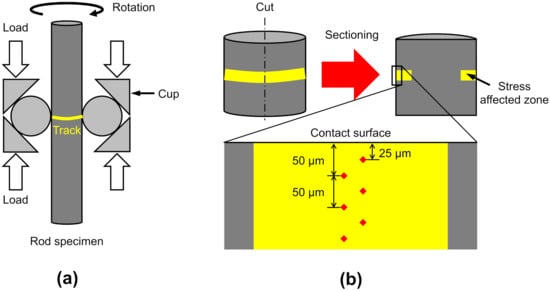
Figure 1.
Experimental methods: (a) schematic of rolling contact fatigue testing; (b) specimen sectioning and hardness measurement.
Figure 1b illustrates how the hardness profile of a RCF tested specimen was obtained. After RCF testing, the cylinder containing the track was first cut through the middle to show its cross-section, and then the surface was ground and polished followed by micro-indentation tests conducted below the centre of the track using an INNOVATEST Falcon 511 Vickers hardness tester (INNOVATEST Europe, Maastricht, The Netherlands). During each micro-indentation test, a Vickers indenter was loaded at 200 gf with a dwell time of 15 s, and the hardness value was calculated according to the size of the indent. The indents were distributed in two rows that were perpendicular to the contact surface. Within each row, the indents were equally spaced with a distance of 50 m to avoid the influence from neighbouring indents. One indentation row was started from 50 m below the contact surface, whilst the other was started from 25 m below the contact surface, so a finer hardness distribution along the depth could be obtained. For each specimen, the tests were repeated four times for averaging. The hardness profile of the original specimen was also obtained.
3. Results and Discussion
3.1. Characterisation and Hardness Profiles
Figure 2a shows the microstructure of the material in the original state, exhibiting tempered martensite. Figure 2b presents the microstructure below the contact surface after running for 7.91 × 10 cycles. The micro-indentation rows indicate the centre of the contact. No significant microstructural alterations were introduced by the RCF tests. Figure 3 shows the hardness profiles of the RCF tested specimens as well as the original state. It can be seen that the RCF tests led to significant subsurface material hardening. For all three specimens, the hardness profiles show a similar trend. With increasing depth, the hardness first rapidly increases, peaking at 50–100 m and then gradually decreases to the original state at around 200 m. Moreover, when the number of cycles increases, the extent of material hardening increases overall.
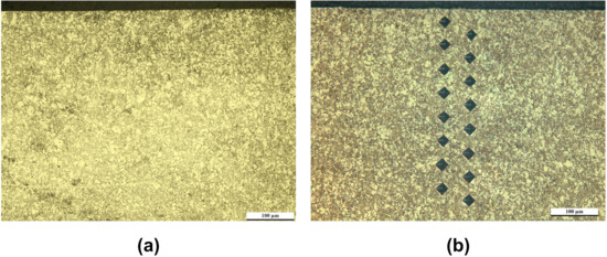
Figure 2.
Optical microscopic images of the microstructure in the original state (a) and after RCF testing for 7.91 × 10 cycles (b).
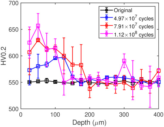
Figure 3.
Subsurface Vickers hardness profiles of the RCF tested specimens.
The hardness increase in the specimens can be attributed to work hardening. It is well established that a plastic flow exists during rolling contact once the yield strength of the material is exceeded [21]. On the one hand, it can be expected that the plastic strain amplitude within each stress cycle is positively correlated with the applied stress. On the other hand, the stress state within contact bodies can be described by Hertzian theory [2], where the shear stress components peak at the subsurface. Hence, the unique hardness profiles of the specimens indicate a strong correlation between the subsurface stress state and the detected material hardening.
3.2. Stress State under Hertzian Contact
The distribution of orthogonal shear stress is calculated based on the Hertzian contact theory. Given the contact geometry of ball-on-rod testing, the contact surface is an ellipse with its long axis along the length of the rod and its short axis along the circumference of the rod. As schematically shown in Figure 4a, a coordinate system is established by defining the centre of the contact ellipse to be the origin of coordinates (0, 0, 0), the direction of the long axis to be the x axis, the direction of the short axis to be the y axis and the depth below the contact centre to be the z axis. Thus, during RCF testing, the over-rolling direction (ORD) is along the y axis, and the measured hardness profiles lie in the plane with . For generality, the coordinates used in the calculation are normalised by the half-long axis of the contact ellipse, a. By referring to the analysis by Johnson [2], a in this research is calculated to be 209 m.
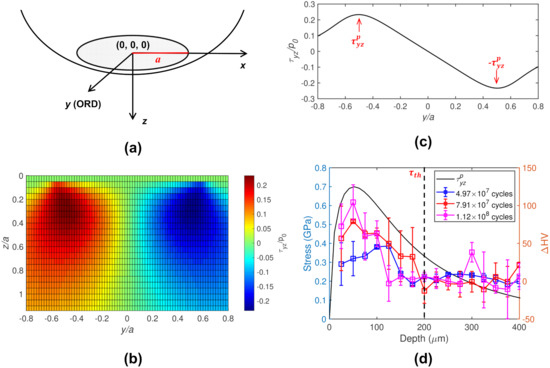
Figure 4.
Stress state under Hertzian contact: (a) defined coordinate system for Hertzian contact; (b) distribution of in plane; (c) distribution of along y axis at ; (d) comparison between the evolving trend of and the profiles at the subsurface.
According to Sackfield et al. [22], the orthogonal shear stress component with respect to the maximum contact pressure () is given by:
where k (<1) is the ellipticity of the contact ellipse, and s and L are parameters used in the elastic contact analysis. The value of s equals the positive root of the following equation:
and the value of L is given by:
where
Using the above equations, the distribution of within the plane of the measured hardness profiles is presented in Figure 4b. It can be seen that the subsurface material experiences alternating shear stress with ball over-rolling. Figure 4c illustrates the distribution of along the y axis at the depth of , where peaks twice with the same magnitude but in opposite directions. In this respect, the distribution of peak orthogonal shear stress () with respect to the depth is plotted in Figure 4c and is compared with the corresponding hardness change (HV). It can be seen that the variation trend of agrees well with that of HV, which indicates that orthogonal shear stress is responsible for the detected work hardening under RCF. and HV both peak at a depth of 0.3a. It should be noted that in the plane, another shear stress component, the maximum shear stress, which is derived from the normal stress components in y and z directions, is also present, whereas this shear stress component peaks at a depth of 0.4a and is hence excluded from the responsible stress component for subsurface hardening. A similar conclusion was also drawn by Fu and Rivera-Díaz-del-Castillo [4] who investigated microstructural alterations in RCF tested bearing inner rings and found was related to subsurface hardening, while the maximum shear stress was related to the formation of white etching bands.
3.3. Work Hardening Model
To describe the subsurface material hardening during RCF, a mathematical model is proposed. In metals, work hardening results from the increase in dislocation density. Hence, the description of dislocation density evolution in the material undergoing RCF becomes critical. According to Kocks and Mecking [23], the change in dislocation density () with respect to the change in plastic shear strain () can be expressed as:
where b is the magnitude of Burgers vector equal to 0.28 nm for body centred cubic iron, and and f are coefficients that govern dislocation multiplication and annihilation, respectively. The values of and f depend on material and deformation conditions which can be calculated based on the thermodynamic approach by Galindo-Nava [24]. In this respect, Fu and Rivera-Díaz-del-Castillo [4] calculated and f for 100Cr6 to be 0.03 and 0.66, respectively.
The initial dislocation density of the steel () can be estimated via the Taylor relation [25] as:
where is the yield strength of the material, M is the Taylor factor equal to 3, is a material constant equal to 0.3 and is the shear modulus, being 80 GPa for 100Cr6. The yield strength of the steel can be estimated through its hardness using the generally accepted triple relationship [26] . Note and hardness in this relationship are both in GPa. For the bearing steel studied in this research, its hardness is approximately 5.39 GPa, and thus, the calculated is 7.95 × 10 m.
As for the plastic strain during RCF, Fu et al. [27] proposed an equation to calculate the plastic strain amplitude within a cycle () for 100Cr6 as follows:
where is the applied shear stress, and is the threshold shear stress for the onset of plastic response. In this research, is and is at 200 m, which is 0.335 GPa (Figure 4d). Apparently not all of can be stored in the material. Assuming a fixed portion of can be stored with the proportionality termed K, the total accumulated plastic shear strain after a certain number of cycles (N) hence becomes:
The value of K can be obtained by fitting to measured hardness results to be 2.2 × 10. Thus, Equation (5) can be solved, yielding the eventual dislocation density , and the corresponding change in strength () is given by the Taylor relation as:
Likewise, can be converted into HV via the triple relationship.
Using the proposed model, the evolution of the dislocation density along the depth with respect to N is presented in Figure 5a. It can be seen that the dislocation density at the peak position can reach the order of magnitude of 10 m. Accordingly, the hardness profiles of the tested specimens are predicted and compared against the experimental results, as shown in Figure 5b, with good agreement obtained. The slight discrepancies between modelling and experiment for the specimen tested for 4.97 × 10 cycles may be due to the misalignment of the rod during RCF testing, resulting in a higher a value.
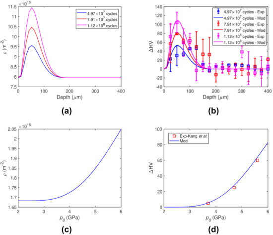
Figure 5.
Modelling results: (a) calculated evolution of dislocation density along depth with respect to N; (b) predicted hardness profiles compared with experiment; (c) calculated evolution of dislocation density at the peak position with respect to for the research by Kang et al. [8]; (d) predicted evolution of hardness at the peak position compared with experiment.
The model is also applied to the experimental results obtained by Kang et al. [8], who revealed the effect of the maximum contact pressure () on the subsurface hardening after ball-on-rod tests. The material studied was also 100Cr6, which is identical to the material studied in this research but with a different heat treatment. This led to an initial hardness value of 7.85 GPa, with the resultant being 1.68 × 10 m. Moreover, the threshold orthogonal shear stress for this material, according to Fu et al. [27], is 0.56 GPa. The other modelling parameters are the same as in this research. By inputting the number of cycles (10 cycles) into the model, the evolution of the dislocation density at the peak position with respect to is calculated, as shown in Figure 5c, and the predicted HV in comparison with the experimental results is presented in Figure 5d, obtaining good agreement.
This research proposes a novel dislocation-based analytical model for predicting subsurface hardening in RCF tested bearing steels. The modelling results presented in Figure 5b,d indicate that the model is capable of predicting subsurface hardness profiles with any given stress state and number of cycles. The model can also be applied to various bearing steels by determining the key parameters and f in Equation (5) and the plastic response under cyclic loading as in Equation (7). Compared with other work hardening models based on FE methods [16,17,18,19,20], the proposed analytical model is simpler and easier to use. More importantly, the model provides insight into the microstructure with the physical process described.
Moreover, the model suggests the existence of the saturation of work hardening that has been widely reported in RCF tested bearing steels [8,13]. According to Equation (5), the dislocation density evolution rate gradually decreases with increasing dislocation density. A plateau is reached when . Hence, the saturation dislocation density can be estimated to be , which is equal to 2.4 × 10 m for 100Cr6 with the given coefficient values.
The proposed model can be further combined with other RCF models regarding crack formation and microstructural alterations to improve their prediction accuracy. It can be expected that the hardness of the matrix significantly affects the crack propagation rate [28]. Moreover, various types of microstructural alterations occurring during RCF such as white etching areas (WEAs), dark etching regions (DERs) and white etching bands (WEBs) are associated with a dislocation rearrangement [29], and the description of dislocation density evolution as presented in this research can facilitate understanding these microstructural features. Moreover, this research presents a methodology for studying the work hardening behaviour of different types of bearing steels undergoing RCF, from experiment to modelling.
4. Conclusions
Rolling contact loading-induced work hardening in GCr15 bearing steel is investigated in this research. Different subsurface hardness profiles are reproduced in rod specimens by RCF tests. Orthogonal shear stress is found to be responsible for work hardening under Hertzian contact. The extent of hardness increase is positively associated with the stress level and number of cycles. A dislocation-based work hardening model is established with material parameters and testing conditions incorporated. The model is capable of predicting the hardness change under RCF with any given rolling contact stress state and number of cycles. The model is validated by experiments from both this research and the literature.
Author Contributions
Funding acquisition and writing—review and editing, H.Y.; methodology, data analysis, modelling, coding and writing—original draft preparation, H.F.; experiments, X.B. All authors have read and agreed to the published version of the manuscript.
Funding
This research was funded by the China Academy of Railway Sciences Corporation Limited (2020YJ148) and the National Natural Science Foundation of China (51971011).
Institutional Review Board Statement
Not applicable.
Informed Consent Statement
Not applicable.
Data Availability Statement
Not applicable.
Acknowledgments
The authors are grateful to Pengpai Zhang for assisting with the rolling contact fatigue tests.
Conflicts of Interest
The authors declare no conflict of interest. The funder had no role in the design of the study; in the collection, analyses, or interpretation of data; in the writing of the manuscript. The funder approved the publication of the results.
References
- Fu, H.; Rivera-Díaz-del Castillo, P.E.J. Approaches to model structural and contact fatigue. In Encyclopedia of Materials: Metals and Alloys; Caballero, F.G., Ed.; Elsevier: Oxford, UK, 2022; pp. 576–588. [Google Scholar]
- Johnson, K. Contact Mechanics; Cambridge University Press: Cambridge, UK, 1987. [Google Scholar]
- Bhadeshia, H.K.D.H. Steels for Bearings. Prog. Mater. Sci. 2012, 57, 268–435. [Google Scholar] [CrossRef]
- Fu, H.; Rivera-Díaz-del Castillo, P.E. Evolution of white etching bands in 100Cr6 bearing steel under rolling contact-fatigue. Metals 2019, 9, 491. [Google Scholar] [CrossRef] [Green Version]
- Arakere, N.K.; Subhash, G. Work hardening response of M50-NiL case hardened bearing steel during shakedown in rolling contact fatigue. Mater. Sci. Technol. 2012, 28, 34–38. [Google Scholar] [CrossRef]
- Warhadpande, A.; Sadeghi, F.; Evans, R.D. Microstructural Alterations in Bearing Steels under Rolling Contact Fatigue Part 1—Historical Overview. Tribol. Trans. 2013, 56, 349–358. [Google Scholar] [CrossRef]
- Fu, H.; Rydel, J.J.; Gola, A.M.; Yu, F.; Geng, K.; Lau, C.; Luo, H.; Rivera-Díaz-del Castillo, P.E.J. The relationship between 100Cr6 steelmaking, inclusion microstructure and rolling contact fatigue performance. Int. J. Fatigue 2019, 129, 104899. [Google Scholar] [CrossRef]
- Kang, J.H.; Vegter, R.H.; Rivera-Díaz-del Castillo, P.E.J. Rolling contact fatigue in martensitic 100Cr6: Subsurface hardening and crack formation. Mater. Sci. Eng. A 2014, 607, 328–333. [Google Scholar] [CrossRef]
- Liang, X.; Zhao, G.H.; Owens, J.; Gong, P.; Rainforth, W.M.; Rivera-Díaz-del Castillo, P.E.J. Hydrogen-assisted microcrack formation in bearing steels under rolling contact fatigue. Int. J. Fatigue 2020, 134, 105485. [Google Scholar] [CrossRef]
- Kang, J.H.; Rivera-Díaz-del Castillo, P.E.J. Fatigue in martensitic 100Cr6: Relationship between rolling contact fatigue microstructural transitions and repetitive push testing. Mater. Sci. Eng. A 2014, 614, 214–222. [Google Scholar] [CrossRef]
- Christ, H.J.; Sommer, C.; Mughrabi, H.; Voskamp, A.P.; Beswick, J.M.; Hengerer, F. Fatigue behaviour of three variants of the roller bearing steel SAE 52100. Fatigue Fract. Eng. Mater. Struct. 1992, 15, 855–870. [Google Scholar] [CrossRef]
- Hahn, G.T.; Bhargava, V.; Chen, Q. The cyclic stress-strain properties, hysteresis loop shape, and kinematic hardening of two high-strength bearing steels. Metall. Trans. A 1990, 21, 653. [Google Scholar] [CrossRef]
- Bhattacharyya, A.; Subhash, G.; Arakere, N. Evolution of subsurface plastic zone due to rolling contact fatigue of M-50 NiL case hardened bearing steel. Int. J. Fatigue 2014, 59, 102–113. [Google Scholar] [CrossRef]
- Merwin, J.E.; Johnson, K.L. An analysis of plastic deformation in rolling contact. Proc. Inst. Mech. Eng. 1963, 177, 676–690. [Google Scholar]
- Bhargava, V.; Hahn, G.T.; Rubin, C.A. An elastic-plastic finite element model of rolling contact. II: Analysis of repeated contacts. J. Appl. Mech. 1985, 52, 75–82. [Google Scholar] [CrossRef]
- Bhargava, V.; Hahn, G.T.; Rubin, C.A. Analysis of rolling contact with kinematic hardening for rail steel properties. Wear 1988, 122, 267–283. [Google Scholar] [CrossRef]
- Hahn, G.; Bhargava, V.; Rubin, C.A.; Chen, Q.; Kim, K. Analysis of the rolling contact residual stresses and cyclic plastic deformation of SAE 52100 steel ball bearings. J. Tribol. 1987, 109, 618–626. [Google Scholar] [CrossRef]
- Bower, A.F. Cyclic hardening properties of hard-drawn copper and rail steel. J. Mech. Phys. Solids 1989, 37, 455–470. [Google Scholar] [CrossRef]
- Howell, M.; Hahn, G.T.; Rubin, C.A.; McDowell, D.L. Finite element analysis of rolling contact for nonlinear kinematic hardening bearing steel. J. Tribol. 1995, 117, 729–736. [Google Scholar] [CrossRef]
- Pandkar, A.S.; Arakere, N.; Subhash, G. Microstructure-sensitive accumulation of plastic strain due to ratcheting in bearing steels subject to rolling contact fatigue. Int. J. Fatigue 2014, 63, 191–202. [Google Scholar] [CrossRef]
- Fu, H.; Galindo-Nava, E.; Rivera-Díaz-del Castillo, P.E.J. Modelling and characterisation of stress-induced carbide precipitation in bearing steels under rolling contact fatigue. Acta Mater. 2017, 128, 176–187. [Google Scholar] [CrossRef]
- Sackfield, A.; Hills, D.A.; Nowell, D. Mechanics of Elastic Contacts; Elsevier: Amsterdam, The Netherlands, 2013. [Google Scholar]
- Kocks, U.; Mecking, H. Physics and phenomenology of strain hardening: The FCC case. Prog. Mater. Sci. 2003, 48, 171–273. [Google Scholar] [CrossRef]
- Galindo-Nava, E.I.; Sietsma, J.; Rivera-Díaz-del Castillo, P.E.J. Dislocation annihilation in plastic deformation: II. Kocks-Mecking Analysis. Acta Mater. 2012, 60, 2615–2624. [Google Scholar] [CrossRef]
- Nabarro, F.R.N.; Basinski, Z.S.; Holt, D.B. The plasticity of pure single crystals. Adv. Phys. 1964, 13, 193–323. [Google Scholar] [CrossRef]
- Tabor, D. The hardness and strength of metals. J. Inst. Met. 1951, 79, 1. [Google Scholar]
- Fu, H.; Song, W.; Galindo-Nava, E.I.; Rivera-Díaz-del Castillo, P.E.J. Strain-induced martensite decay in bearing steels under rolling contact fatigue: Modelling and atomic-scale characterisation. Acta Mater. 2017, 139, 163–173. [Google Scholar] [CrossRef]
- Slack, T.S.; Raje, N. A Review of Rolling Contact Fatigue. J. Tribol. 2009, 131, 041403. [Google Scholar]
- Fu, H.; Rivera-Díaz-del Castillo, P.E.J. A unified theory for microstructural alterations in bearing steels under rolling contact fatigue. Acta Mater. 2018, 155, 43–55. [Google Scholar] [CrossRef]
Publisher’s Note: MDPI stays neutral with regard to jurisdictional claims in published maps and institutional affiliations. |
© 2022 by the authors. Licensee MDPI, Basel, Switzerland. This article is an open access article distributed under the terms and conditions of the Creative Commons Attribution (CC BY) license (https://creativecommons.org/licenses/by/4.0/).