Abstract
Implants are the most popular option for restoring the facial anatomy in the event of a mishap. The commercially available craniofacial implants are of standard shapes, which need to be tailored and shaped to accurately fit the patient’s anatomy. The manual shaping of the implant to match the bone contours is conducted during surgical operation, and is a cumbersome and inaccurate process. Recent breakthroughs in computer-aided design, analysis, and additive manufacturing (AM) have allowed the precise and rapid manufacture of bespoke scaffolds for difficult anatomical restoration. The goal of this research is to investigate the use of scaffolds for craniofacial reconstruction and their fabrication using electron-beam additive manufacturing (EBAM). Personalized cheekbone scaffolds are additively fabricated using Ti6Al4V and subjected to compression testing. Finally, the scaffold design with the highest compressive strength is subjected to biomechanical analysis. The biomechanical analysis results indicate that the maximum Von Mises stress (40 MPa) and equivalent strain (0.4 µm) are significantly low in magnitude, thus providing a desirable implant that is both flexible and stable. The custom-designed cheekbone scaffold manufactured with AM technology not only aids in bone-implant ingrowth but also helps in reducing implant weight and ensuring implant stability and long-term effectiveness.
1. Introduction
Craniofacial reconstruction encompassing the head, neck, face, and jaws is a difficult procedure due to the presence of multiple essential organs around the damaged region [1]. As a result, greater caution is required while operating in these areas of the body. For example, the implants used to restore face geometry must be chosen carefully, considering the biocompatibility of the material, implant geometry and shape, patient comfort, fitting accuracy, desired strength, and so on. Indeed, a minor misalignment of the facial proportions caused by the implant chosen might have an impact on the patient’s facial characteristics, appearance, individual uniqueness, and, ultimately, wellbeing. Though implants are commercially available for craniofacial restoration, they are of standard shapes that must be adjusted and sculpted to fit the patient perfectly. The manual shaping of commercially available implants to match bone shapes during surgical procedures is a time-consuming and inaccurate process [2]. The repetitive physical bending and adjusting of the implants, without a doubt, causes fatigue, stress, and implant failure. However, recent technological and software breakthroughs have greatly simplified the craniofacial reconstruction procedure, resulting in implants that are both efficient and effective in matching the anatomy. Thus, any complex design structure can be generated from a computer tomography (CT) scan as a result of the improvement in imaging techniques and the availability of user-friendly image processing software.
The choice of implant material is an essential criterion in addition to the reconstruction design process, technologies, and software. When compared to other metal biomaterials, titanium is a great option for biomedical applications because of its exceptional strength (strength to weight ratio), corrosion resistance, and superior biocompatibility [3]. Titanium and its alloys exhibit a modulus of elasticity (~110 MPa) approximately half that of other metal biomaterials such as stainless steel (~200 GPa) and cobalt-chromium (~210 GPa) [4,5]. The other promising property that makes titanium and its alloys unique from other metallic biomaterials, is the formation of a thin oxide passive layer on its surface, which protects it from corrosion and promotes osseointegration [6]. Osseointegration is defined as the direct functional and structural connection between the implant material and the surrounding bone tissue. A good integration of implant and bone is essential for the stability of the implant and its long-term usage.
Numerous studies have reported that dense titanium implants may develop a stress-shielding effect, instability, and implant loosening due to the difference in the modulus of elasticity between the implant and the bone [7]. Although titanium and its alloys have a lower Young’s modulus with respect to other bio-metals, it is still high when compared to that of bone (10–30 GPa). This difference in Young’s modulus often leads to the stress-shielding effect and implant instability, which cause a loosening of the implant [8]. Hence, to overcome the stress-shielding effect on the surrounding bone, the designed solid titanium implant is transformed into a scaffold (porous) structure, thus reducing the weight and matching the bone properties. The use of titanium scaffold (Ti6Al4V) is a great alternative not only to reduce the stress-shielding effect but also to improve osseointegration [9]. In addition, the scaffold should also retain sufficient mechanical strength to withstand the loads while maintaining low stiffness.
Implants with an open porous structure enhance bonding at the implant/bone interface, thus providing an opportunity for the soft tissue to interlock with the implant and for ingrowth formation [10]. However, they are complex structures and cannot be fabricated effectively and efficiently with the traditional manufacturing process. Additive manufacturing (AM) provides an opportunity to fabricate a homogenous porous structure with controlled porosity and cell distribution. Several research studies have demonstrated the viability of additively manufactured scaffolds as a suitable solution for bone defects, thus maximizing the speed of recovery and bone repair [11,12]. Furthermore, additively manufactured customized scaffolds suit the individual anatomy and remain in place for longer periods, thus providing greater flexibility, higher stability, and good cosmetic results. Electron-beam additive manufacturing (EBAM) is one of many AM processes that has repeatedly demonstrated its ability to build fully dense and porous metallic components from powder using digital data [13]. This technology was developed and patented by ARCAM AB (Sweden). Among several three-dimensional (3D) printing technologies, EBAM has been regarded as the fastest-emerging technology in the fabrication of medical implants and devices from direct digital computer-aided-design (CAD) models with Food and Drug Administration (FDA) and Conformité Européene (CE) approval [14].
Finite element analysis (FEA) is a numerical technique to simulate the boundary and loading conditions of the 3D model and to obtain results with good accuracy. ANSYS and ABAQUS are two widely used numerical simulation software in which the material and loading conditions are applied to obtain the required results of stress, strain, and deformation. FEA has been actively employed as a simulation tool in the design and development of medical implants, as well as in comprehending the complicated nature of the human body [15]. FEA outcomes are expanding in medical investigations since they extrapolate clinical results in advance without surgery. FEA allows great flexibility in dealing with complex structures composed of multiple materials [16,17]. A customized implant, in addition to having a customized geometry and precise construction to ensure direct contact with the surrounding bone tissues, should also have sufficient mechanical strength for long-term stability. Hence, FEA can be a good option to analyze these intricate structures and to study their mechanical viability under loading conditions.
The purpose of this research is to investigate craniofacial reconstruction scaffolds and how they are manufactured utilizing AM. A CT-scan is performed on a patient with a lesion on the left cheekbone, and the images are processed using MIMICS 18.0 image-processing software (Materialise NV, Leuven, Belgium). MIMICS is chosen because it is one of the most extensively used image-processing programs for creating 3D surface anatomical models from CT-scanned two-dimensional (2D) data [18]. The obtained 3D model is used as a template for the design of a customized facial-cheek implant. The bulk facial-cheek implant is transformed into three different scaffolds of dode thick, dode medium and dode thin structures to study their viability in implants. The three scaffold design structures are fabricated using EBAM and their compressive strengths are studied. The scaffold with the best mechanical strength is selected as a craniofacial implant and its biomechanical performance based on loading conditions is investigated.
2. Materials and Methods
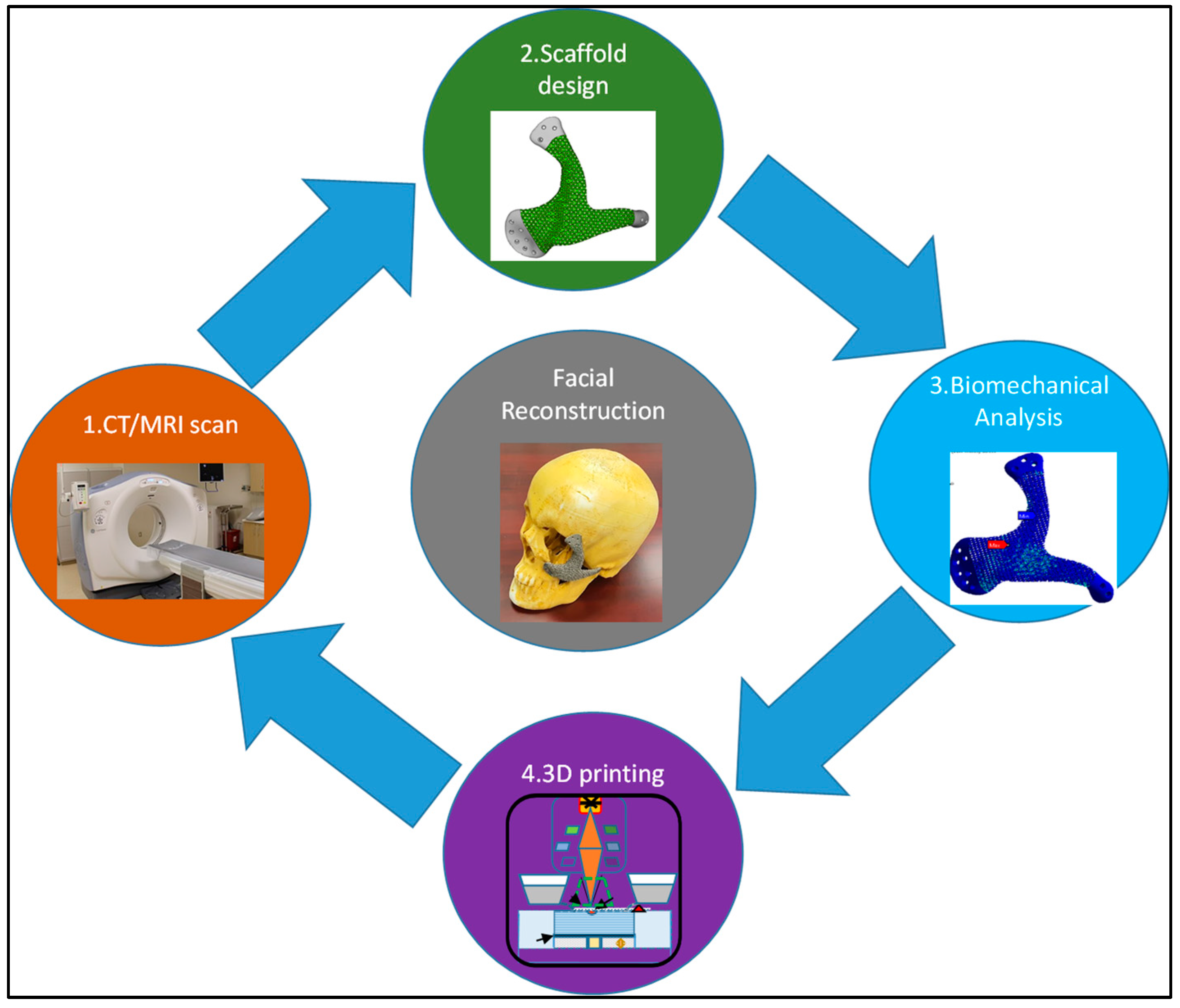
The methodology applied to the reconstruction of craniofacial defects as illustrated in Figure 1, consisted of four major steps involving a CT/MRI scan of the patient, scaffold design for the cellular penetration, AM of the titanium scaffold (Ti6Al4V) using EBAM and finally the biomechanical analysis of the scaffold with superior mechanical properties to study the impact of loading.

Figure 1.
Schematic data flow in the reconstruction of craniofacial defects.
2.1. CT/MRI Scan
The CT/MRI scan data of the patient were uploaded into MIMICS 18.0, a medical modeling software which was used to convert the DICOM (Digital Imaging and Communication in Medicine) data set of 2D images into a 3D surface model by stacking them upon each other. Since the 3D model shows the entire scanned anatomy, the dataset had to be segmented to visualize only the region of interest. This was achieved using thresholding, segmentation, and region-growing techniques whereby the soft and hard tissues were separated and only the region of interest, which includes the facial bone, was selected. As illustrated in Figure 2, the obtained 3D model from the CT-scan contained the large data model, which included the skull with the positioning pads for stabilizing the head and the cervical spine. Segmentation and region growing were used to separate the positioning pads (Figure 2a) and then the cervical spine (Figure 2b) to obtain the region of interest for the skull model (Figure 2c).
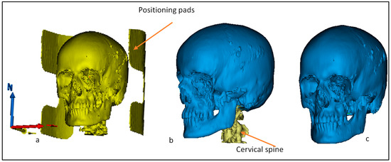
Figure 2.
Steps involved in the segmentation of (a) positioning pads and (b) cervical spine to obtain the region of interest—(c) skull.
2.2. Implant Design Customization
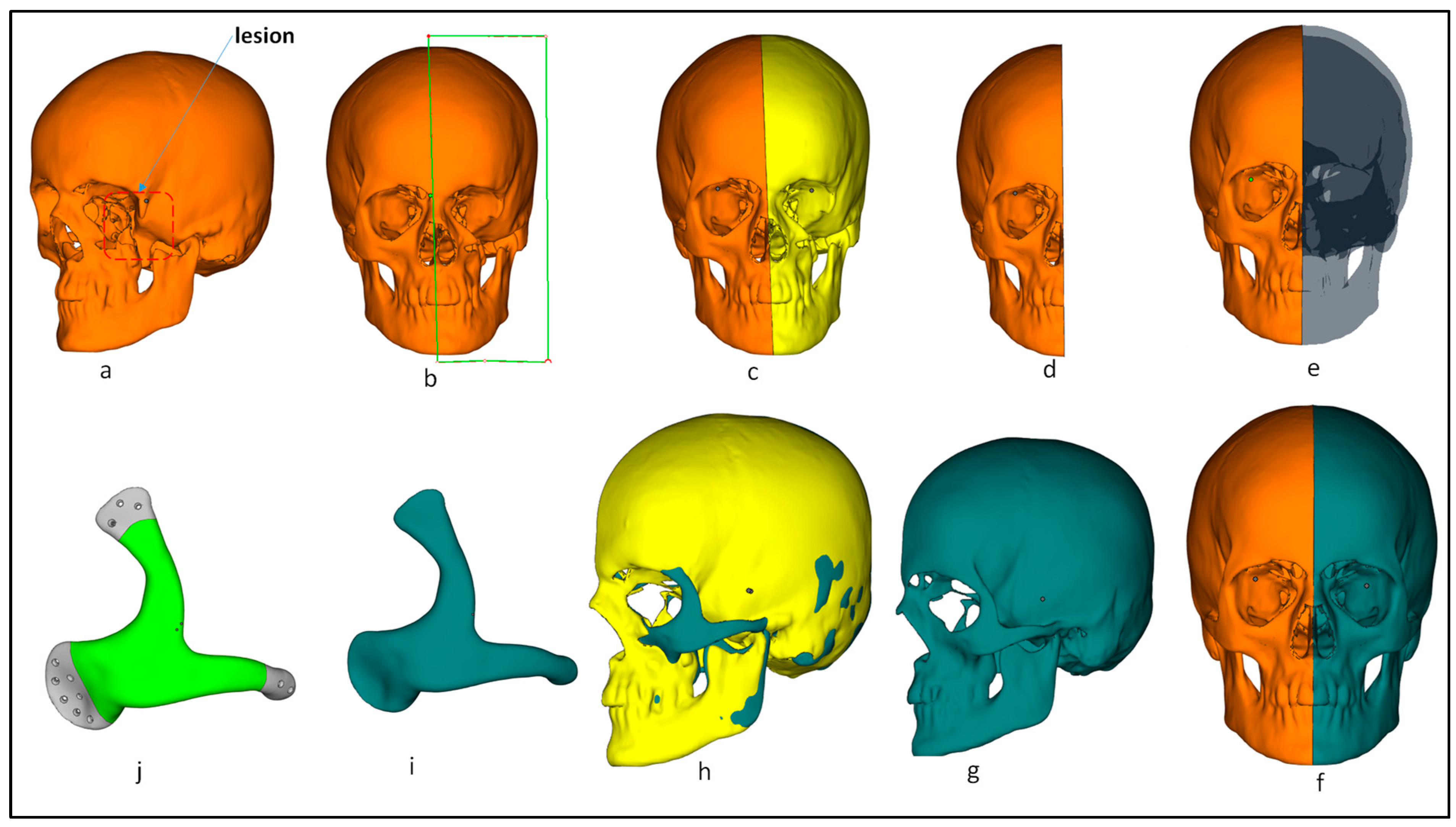
The mirror-imaging technique was used in the reconstruction of the craniofacial implant. Mirroring is one of the most widely used techniques in the design of implants owing to its simplicity and ease of use. There are several research studies that have used this technique in the reconstruction of cranial, mandibular, and facial implants [19,20,21]. In this technique, the defective region is replaced and mirrored by the healthy opposite region to restore excellent facial symmetry. Figure 3 illustrates the steps involved in the customized implant design where the lesion can be seen on the left side (Figure 3a) of the cheekbone (zygoma). Mirror-image reconstruction was performed by selecting the midplane (Figure 3b) in order to resect the facial 3D model to obtain symmetrical left and right regions (Figure 3c). The defective facial region on the left was removed (Figure 3d) and mirrored with the healthy right facial region to obtain a symmetrical facial anatomy (Figure 3e,f). Boolean subtraction (Figure 3h) was performed between the mirrored healthy facial region (Figure 3g) and the defect-free right facial region (Figure 3d) to obtain the customized facial implant (Figure 3i). Tapered screw-holes were designed for the smooth insertion of the screws.

Figure 3.
Step-by-step process from the patient with lesion to the finally obtained customized facial implant: (a) patient with left lesion; (b) midplane selection for resection of facial bone; (c) facial bone after resection; (d) removal of left-side tumor region; (e) mirroring the healthy right side of facial bone; (f) obtaining the healthy mirrored right-side region; (g) healthy mirrored right-side region; (h) performing Boolean operation between the left tumor region (yellow) and obtained mirror right region (teal green); (i) customized facial implant after the Boolean operation; (j) tapered screw-holes introduction for smoother fixation.
The obtained facial implant acted as a template for the scaffold design. The scaffold design should be an accurate representation of both the physiology and cell matrix of the bone. The trabecular structures were found to be close to that of the physical and mechanical properties of bone [22]. Three different trabecular scaffolds of dode structures, including dode thin, dode medium, and dode thick, were selected from Magics 18.0 (Materialise NV, Leuven, Belgium) as shown in Figure 4. Dode structures have previously been used as a trabecular morphology to study the ingrowth of bone cells and the stability of implants [23,24]. The cell size of the dode structures was 3 mm unit cell and the strut thicknesses for dode thin, dode medium and dode thick were 0.22 mm, 0.41 mm and 0.60 mm, respectively. The inner portion of the facial implant (green) was taken as a template and transformed into three different scaffold designs as shown in Figure 5.
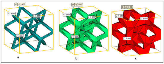
Figure 4.
Trabecular structures with unit cell size of 3 mm: (a) dode thin with strut size of 0.22 mm, (b) dode medium with strut size of 0.41 mm and (c) dode thick with strut size of 0.60 mm.
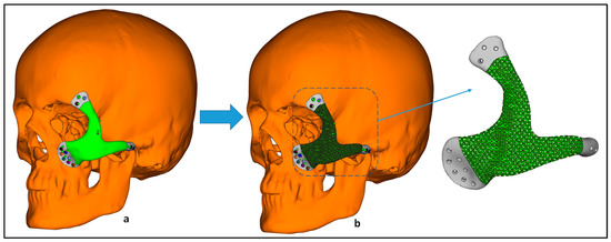
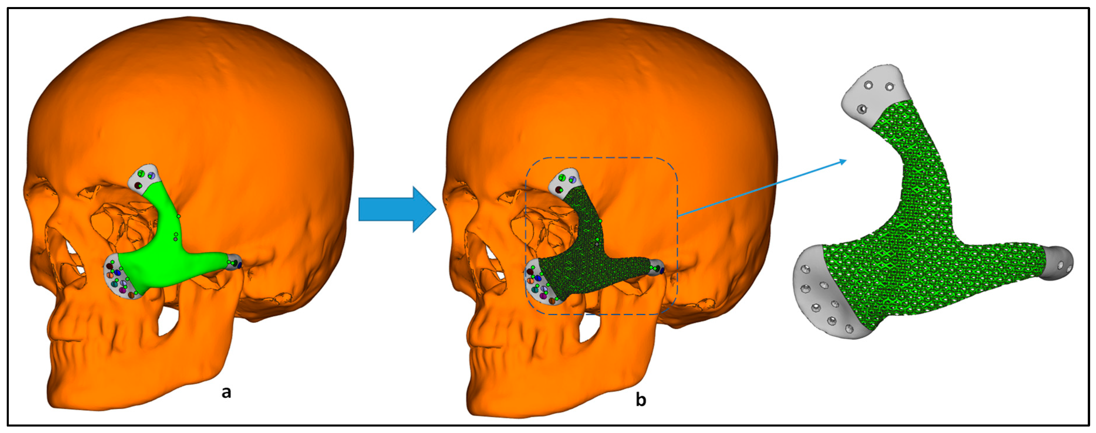
Figure 5.
Transformation of (a) bulk craniofacial implant into a (b) scaffold to promote cell interaction.
2.3. EBAM Fabrication
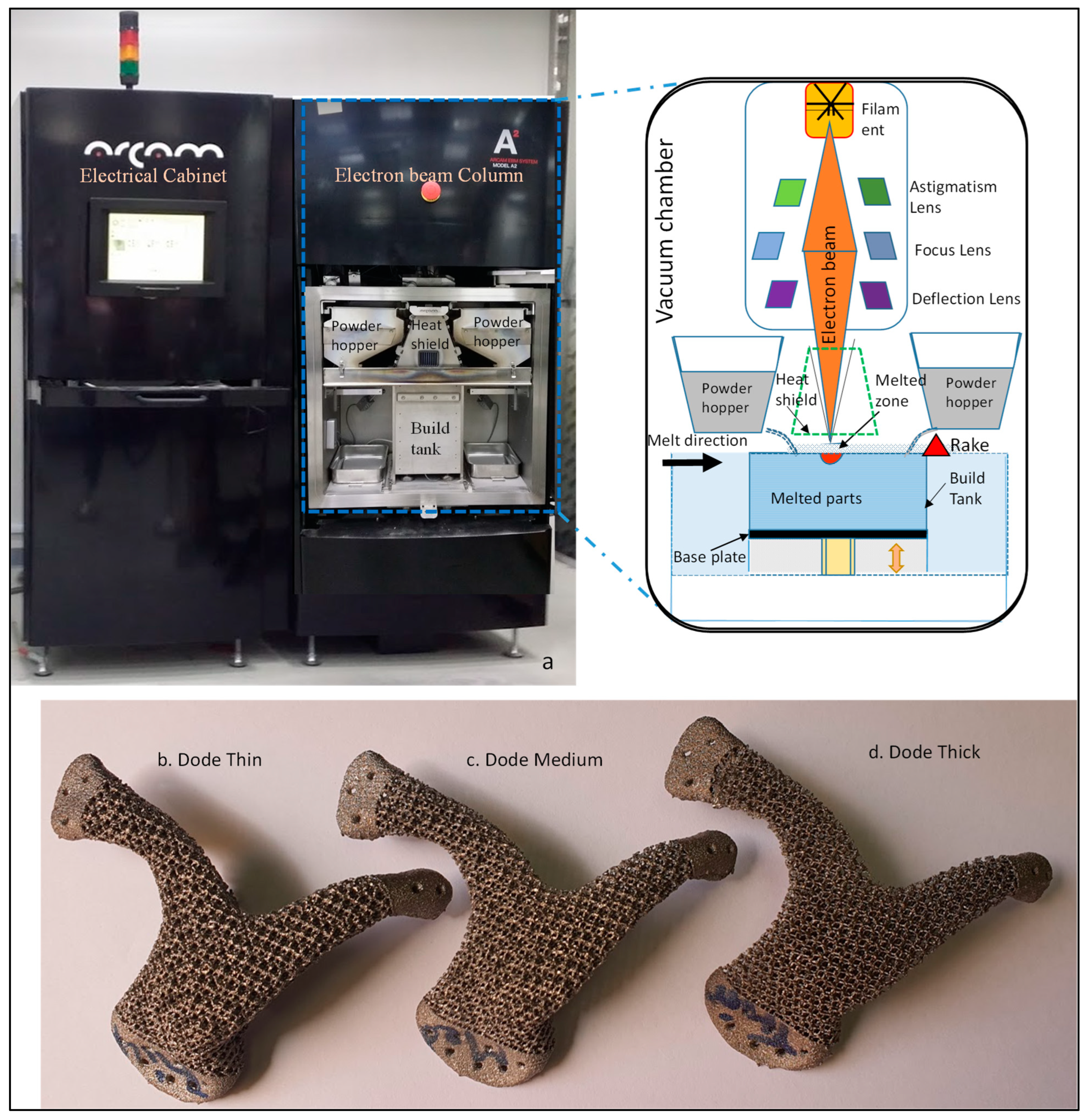
The craniofacial implant scaffolds were imported into ARCAM’s EBAM A2 machine (Arcam AB, Mölndal, Sweden) for the fabrication of the titanium (Ti6Al4V) scaffolds. EBAM is a powder-bed fusion process of producing a fully dense metallic part using a high-intensity beam of electrons to melt the powder particles (Ti6Al4V) completely in a layer-by-layer fashion based on the computer-generated model. The whole process took place in high vacuum, thus preventing the Ti6Al4V from oxidizing and the interference of the atmosphere or other contaminations, when heated [25]. The parts produced through the EBAM process are stress free with mechanical and chemical properties better than casting and forging [26]. Figure 6a explains the schematic working principle of the EBAM process where the high-intensity beam of electrons emitted from the tungsten filament is controlled by the deflection lens, and scans and melts specific areas of Ti6Al4V, thus instantly converting the kinetic energy into thermal energy. The Ti6Al4V liquefies and takes the shape of the desired CAD model. Helium gas was injected during the process to guarantee thermal stability and to dissipate the electrical charges from the melt surface. After each melt cycle, the build platform was lowered and a layer of new powder particles (Ti6Al4V) was raked evenly onto the previously solidified layer. Arcam’s titanium powder (Ti6Al4V) with a chemical composition of 6.04% aluminum, 4.05% vanadium, 0.0013% carbon, 0.0107% iron, 0.13% oxygen, and the rest titanium was used in this investigation.
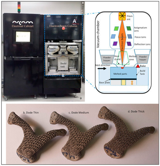
Figure 6.
(a) Schematic diagram of the EBAM work cycle, and the fabricated scaffolds of (b) dode thin, (c) dode medium and (d) dode thick.
Figure 6b–d illustrate the EBAM-fabricated scaffolds of dode thin, dode medium and dode thick. The loosely trapped powder within the implant was removed in ARCAM’s powder-recovery system (PRS) through blasting with highly pressurized air mixed with Ti6Al4V. The weights of all three fabricated scaffolds were measured using a digital weighing scale (Ohaus Corporation, Parsippany, NJ, USA), as shown in Table 1.

Table 1.
Weighing scale reading of the three scaffolds.
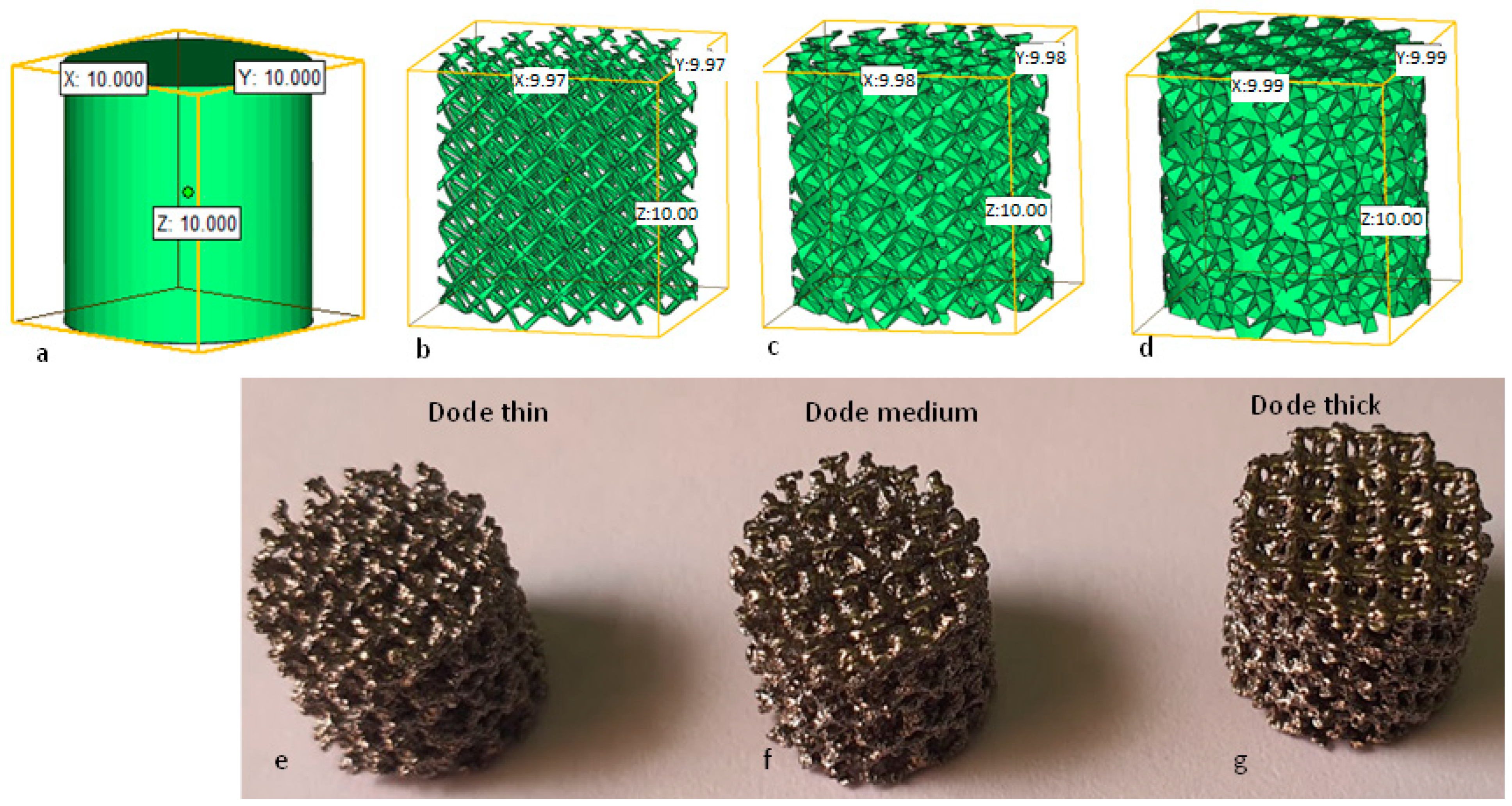
Three cylinders with a diameter and height of 10 mm were designed (Figure 7a) and transformed into scaffold structures of dode thin, dode medium and dode thick (Figure 7b–d) to perform the standard mechanical testing on scaffolds. These scaffolds were then fabricated using the EBAM machine as shown in Figure 7e–g.

Figure 7.
(a) A custom-designed cylinder of 10 × 10 mm2, and its transformation into three scaffold structures of (b) dode thin, (c) dode medium, (d) dode thick, and its counterpart (e–g) EBAM-fabricated scaffolds.
2.4. Compression Test
The cylindrical scaffolds were subjected to an axial compression test using an Instron universal testing machine to study the mechanical strength of each scaffold design. The loading direction was kept parallel to the direction of the deposited layer, as shown in Figure 8. A displacement-controlled crosshead speed of 1 mm/min was recorded.
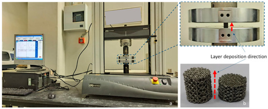
Figure 8.
(a) Compression test performed on the cylindrical scaffolds and (b) cylindrical scaffold before and after compression tests.
3. Finite Element Analysis
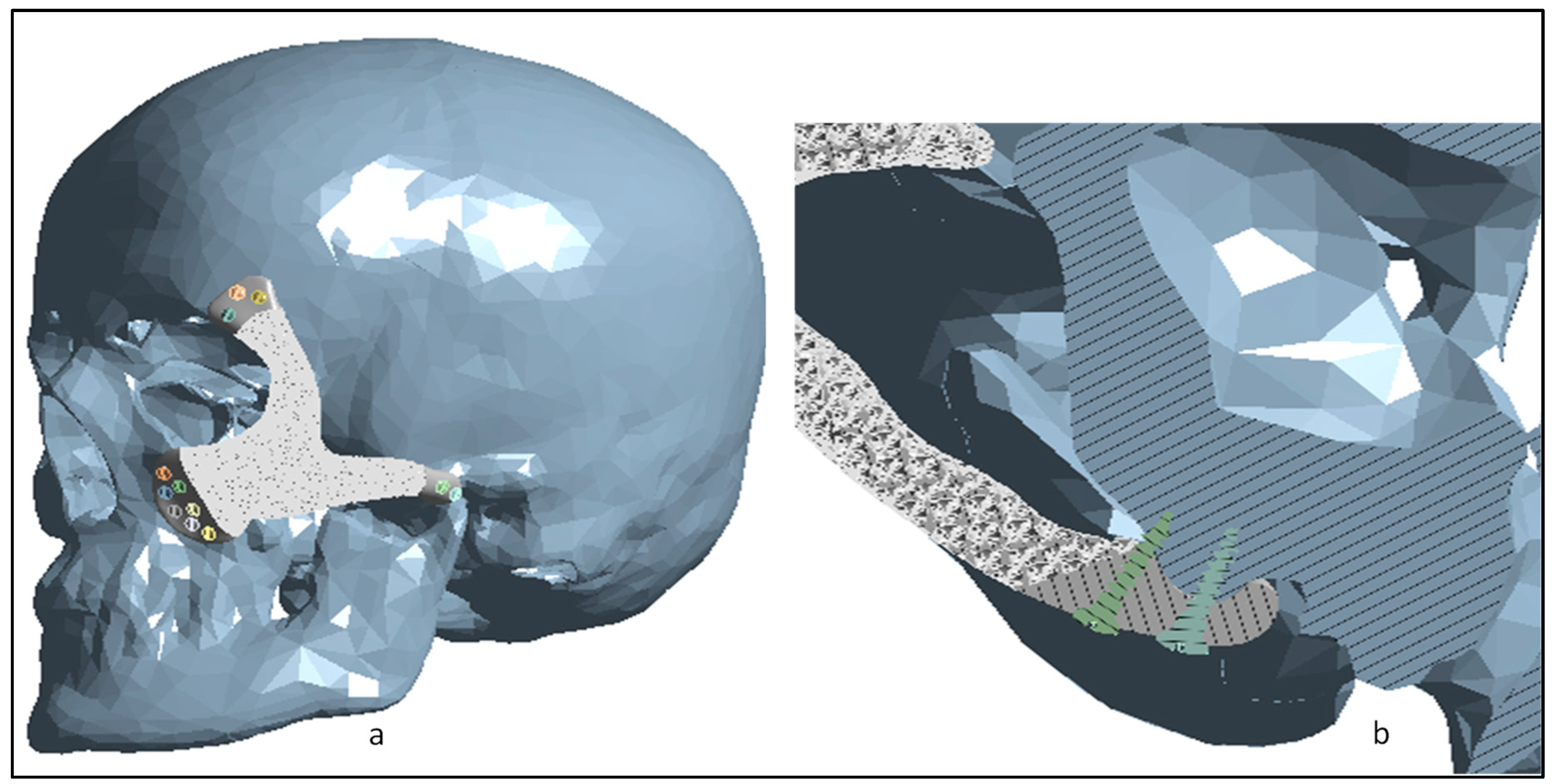
FEA was carried out on the scaffolds to study the biomechanical effects on the implant–bone interface based on the loading conditions. ANSYS workbench 19.0 was used to carry out the FEA on the 3D Finite Element Model (FEM) containing the skull model, craniofacial implant and the implant–bone fixing screws as shown in Figure 9a. A cross-section view of the insertion of screws into the implant–bone region is illustrated in Figure 9b. The physical interface between all the elements was taken to be bonded on surface-to-surface contact.

Figure 9.
(a) The 3D FEM consisting of the skull, craniofacial implant and the fixation screws, and (b) cross-section view of the screw insertion into the implant–bone region.
3.1. Material Properties
All the materials in this study were regarded as homogenous, isotropic, and linear elastic. The designed FEM was assigned with different material properties [3]. The skull had cortical bone characteristics, whereas the customized scaffolds with the fixation screws were assigned as Ti6Al4V ELI material. Table 2 illustrates the material properties of the FEM.
Table 2.
Material properties used in the computational model [27].
3.2. Boundary Conditions
The loading and boundary conditions of the FEM are shown in Figure 10. The skull was fixed around the bottom neck region and a static force of 50 N was applied to the scaffold. Researchers have used similar kinds of applied force and boundary conditions previously to study the biomechanical effect on craniofacial implants [28].
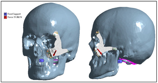
Figure 10.
Boundary conditions and external loads applied to the FEM.
3.3. Mesh Creation and Analysis
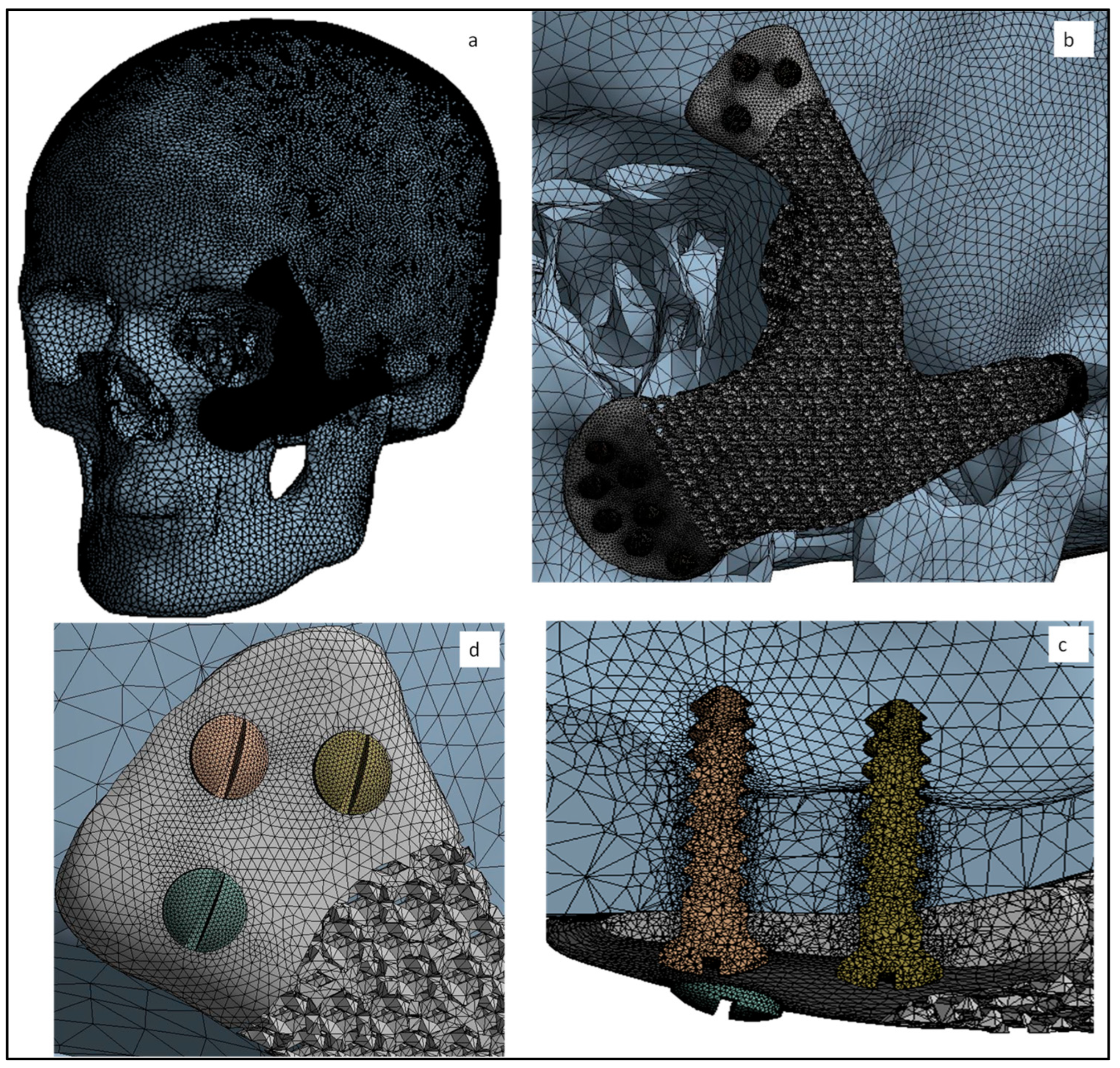
With the enhancement of the refined mesh, the accuracy of the results improved, but there are limitations on how much the mesh size can be reduced due to the computation time and power. In order to save the computation time and cost, the optimum mesh size was used, as shown in Figure 11a,b, resulting in the 1,319,094 elements and 351,917 nodes in the FEM. Adaptive mesh refinement was used to obtain the desired accuracy in the FEA results. A more refined mesh was applied to the fixation screws and its surrounding area as illustrated in Figure 11c,d to improve the analytical precision of stress concentration.
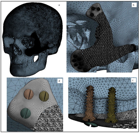
Figure 11.
(a,b) Global view of finite element mesh and a more refined mesh on the (c,d) fixation screws.
4. Results and Discussion
The compression test results of the true stress and strain curve of the designed cylindrical scaffolds can be seen in Figure 12. The dode thick cylindrical scaffold can withstand the highest load of 150 MPa when compared to dode medium (29 MPa) and dode thin (12 MPa) structures. Based on the compressive test results, the dode thick scaffold matches the human bone properties, as the compressive strength of human cortical bone lies in the range of 100 to 150 MPa [29,30,31]. Another major focus of the craniofacial implant, in addition to having a symmetrical design, is the minimization of the stress-shielding effect and matching with the bone properties. The differences between the implant and bone properties lead to bone resorption which further leads to bone loss and screw loosening. Additionally, it decreases the bonding strength between implant and bone. The chances of a stress-shielding effect around the implant-bone interface are negligible as the scaffold matches the bone properties as well as providing the necessary stability with the implant–bone bonding.
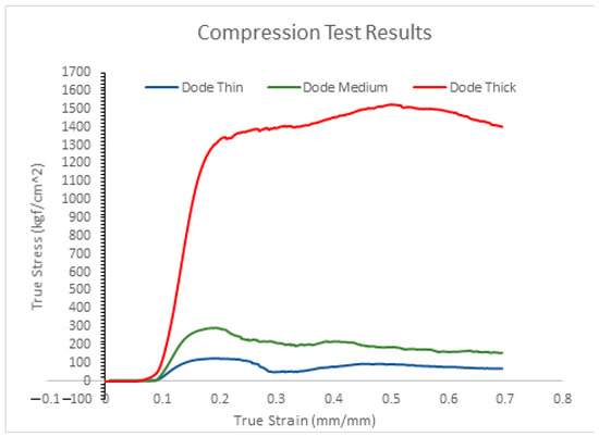
Figure 12.
True stress and strain curves from the compression test results of scaffold structures.
The equivalent Von Mises stress distribution is illustrated in Figure 13a,b where the maximum stress is 40 MPa in the scaffold region. The maximum Von Mises stress observed in the analysis is well below the tensile strength of the scaffold, which is 150 MPa, thus guaranteeing the stability of the implant. Figure 13c,d illustrate the maximum equivalent elastic strain of the implant. Nonetheless, the strain found on the implant is very low, at around 0.4 µm, which is negligible. A lower maximum strain indicates the greater stability and the higher flexibility of the implant, which in turn promotes faster healing [32]. Based on the FEA results, it can be predicted that the custom-designed dode thick facial scaffold can better absorb the stress concentration and minimize the load transformation from the implant to its affixing screws.
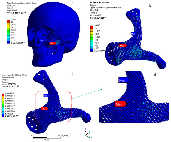
Figure 13.
(a,b) Von Mises stress (MPa) and (c,d) strain distribution on the customized craniofacial scaffold.
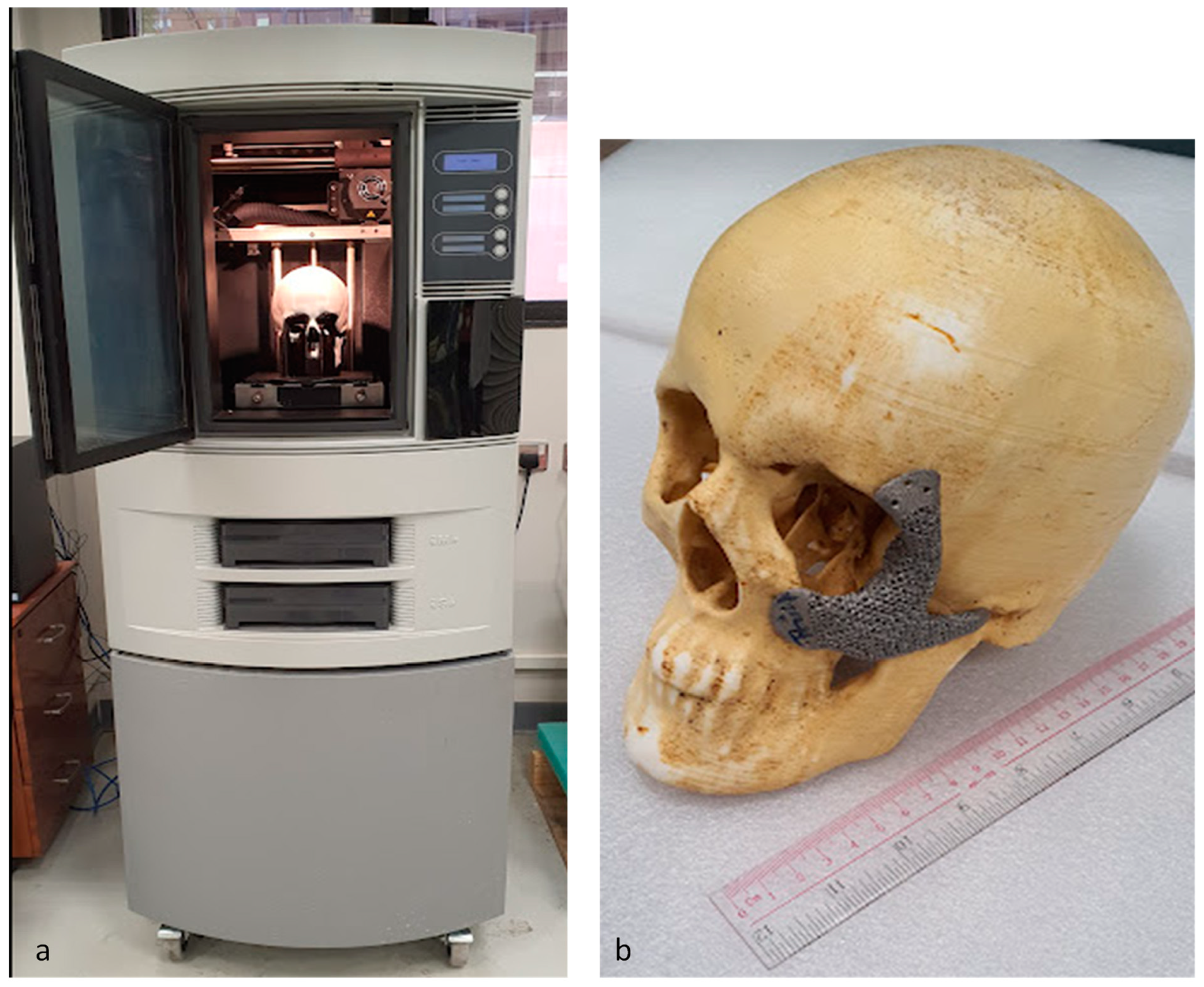
The customized craniofacial scaffold of the dode thick structure and the skull model were fabricated using an EBAM machine and fused-deposition-modeling (FDM) technology, respectively, for fitting and evaluation, as shown in Figure 14. A Stratasys Dimensional Elite 3D printer (Stratasys, Eden Prairie, MN, USA) was used in the fabrication of the skull model using ABS (Acrylonitrile butadiene styrene) material. The customized craniofacial scaffold fits precisely onto the ABS skull model with no dead spaces between them, thus signifying a perfect-fit customized implant, and showing a good aesthetic result.
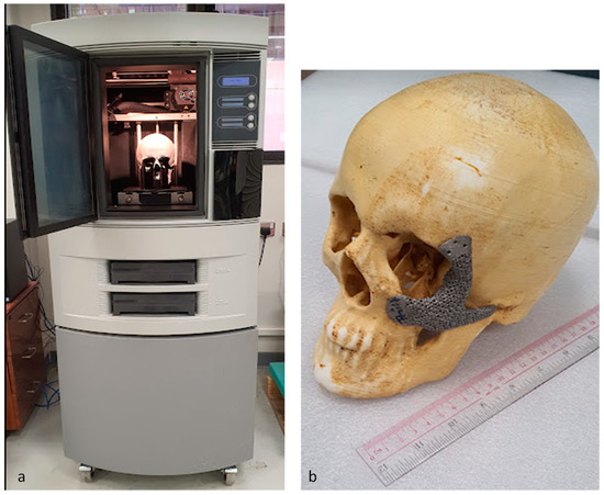
Figure 14.
(a) FDM machine and (b) EBAM-built scaffold fitted on the ABS skull model for validation.
5. Conclusions
Pre-operative surgical planning using a 3D-printed model helps in understanding a patient’s anatomy and increases the efficacy of the surgical operation through pre-surgical simulation with virtual and 3D-printed models. One of the reasons for utilizing the customized implant is that the commercially available solid implants are of standard shapes, which causes the implant to loosen over time due to the stress-shielding effect. Custom-designed or tailor-made implants have been the focus of research for decades. One of the reasons for their limited use until now is their fabrication complexity. Indeed, the fabrication of patient-specific scaffolds has been a challenge, but due to the interventions of metal-fabrication technologies such as EBAM, new possibilities have opened up.
In this study, EBAM-customized scaffolds with mechanical properties closer to those of bone, and an interconnected cellular structure allowing bone-tissue ingrowth, are fabricated and evaluated using compression-strength and FEA. The data obtained from the compression-strength and biomechanical simulation results demonstrate that the newly designed dode thick craniofacial scaffold can survive the loading conditions and maintain the required stability. This research lays the groundwork for designing and fabricating custom-fit face implants, obviating the need for time-consuming and incorrect surgical procedures. The adopted tailored design methodology can also benefit other orthopedic and complicated surgical procedures. Although, Ti6Al4V implants are extensively used for anatomical restoration due to the numerous benefits indicated in the literature. It is essential to explore and improve the capabilities of Ti6Al4V scaffolds by incorporating them with additional materials to strengthen the bond between the bone and the implant.
Author Contributions
Conceptualization, K.M. and S.H.M.; methodology, K.M. and S.H.M.; software, K.M., S.H.M. and S.M.E.; validation, K.M., B.M.A.A. and H.A.; formal analysis, K.M., S.H.M. and S.M.E.; investigation, B.M.A.A., M.K.A. and S.M.E.; resources, H.A.; data curation, S.M.E. and B.M.A.A.; writing—original draft preparation, K.M.; writing—review and editing, K.M., H.A. and S.H.M.; visualization, K.M. and M.K.A.; supervision, H.A. and M.K.A.; project administration, H.A. and M.K.A.; funding acquisition, H.A. All authors have read and agreed to the published version of the manuscript.
Funding
This research was funded through the Researchers Supporting Project number (RSP2022R499), King Saud University, Riyadh, Saudi Arabia.
Data Availability Statement
The data presented in this study are available from the corresponding author on reasonable request.
Acknowledgments
The authors extend their appreciation to King Saud University for funding this work through Researchers Supporting Project number (RSP2022R499), King Saud University, Riyadh, Saudi Arabia.
Conflicts of Interest
The authors declare no conflict of interest.
References
- Hanasono, M.M. Reconstructive Surgery for Head and Neck Cancer Patients. Adv. Med. 2014, 2014, 795483. [Google Scholar] [CrossRef] [PubMed] [Green Version]
- Yang, W.; Choi, W.S.; Wong, M.C.-M.; Powcharoen, W.; Zhu, W.; Tsoi, J.K.-H.; Chow, M.; Kwok, K.-W.; Su, Y. Three-Dimensionally Printed Patient-Specific Surgical Plates Increase Accuracy of Oncologic Head and Neck Reconstruction Versus Conventional Surgical Plates: A Comparative Study. Ann. Surg. Oncol. 2021, 28, 363–375. [Google Scholar] [CrossRef] [PubMed]
- Liu, X.; Chu, P.K.; Ding, C. Surface Modification of Titanium, Titanium Alloys, and Related Materials for Biomedical Applications. Mater. Sci. Eng. R Rep. 2004, 47, 49–121. [Google Scholar] [CrossRef] [Green Version]
- Pilliar, R.M. Modern Metal Processing for Improved Load-Bearing Surgical Implants. Biomaterials 1991, 12, 95–100. [Google Scholar] [CrossRef] [PubMed]
- Niinomi, M. Recent Research and Development in Metallic Materials for Biomedical, Dental and Healthcare Products Applications. Mater. Sci. Forum 2007, 539–543, 193–200. [Google Scholar] [CrossRef]
- de Viteri, V.S.; Fuentes, E. Titanium and Titanium Alloys as Biomaterials; InTechOpen: London, UK, 2013. [Google Scholar]
- Arabnejad, S.; Johnston, B.; Tanzer, M.; Pasini, D. Fully Porous 3D Printed Titanium Femoral Stem to Reduce Stress-Shielding Following Total Hip Arthroplasty. J. Orthop. Res. 2017, 35, 1774–1783. [Google Scholar] [CrossRef] [PubMed]
- Ryan, G.; Pandit, A.; Apatsidis, D. Fabrication Methods of Porous Metals for Use in Orthopaedic Applications. Biomaterials 2006, 27, 2651–2670. [Google Scholar] [CrossRef]
- Ghouse, S.; Reznikov, N.; Boughton, O.R.; Babu, S.; Ng, K.C.G.; Blunn, G.; Cobb, J.P.; Stevens, M.M.; Jeffers, J.R.T. The Design and In Vivo Testing of a Locally Stiffness-Matched Porous Scaffold. Appl. Mater. Today 2019, 15, 377–388. [Google Scholar] [CrossRef]
- In Vivo Testing of Porous Ti-25Nb Alloy Serving as a Femoral Stem Prosthesis in a Rabbit Model. Available online: https://www.spandidos-publications.com/10.3892/etm.2016.3472 (accessed on 26 January 2022).
- Moiduddin, K.; Hammad Mian, S.; Alkindi, M.; Ramalingam, S.; Alkhalefah, H.; Alghamdi, O. An In Vivo Evaluation of Biocompatibility and Implant Accuracy of the Electron Beam Melting and Commercial Reconstruction Plates. Metals 2019, 9, 1065. [Google Scholar] [CrossRef] [Green Version]
- Yang, Y.; Wang, G.; Liang, H.; Gao, C.; Peng, S.; Shen, L.; Shuai, C. Additive Manufacturing of Bone Scaffolds. Int. J. Bioprint. 2018, 5, 148. [Google Scholar] [CrossRef]
- Arcam, A.B. Electron Beam Melting—EBM Process, Additive Manufacturing. Available online: http://www.arcam.com/technology/electron-beam-melting/ (accessed on 7 July 2017).
- Chua, C.K.; Wong, C.H.; Yeong, W.Y. Standards, Quality Control, and Measurement Sciences in 3D Printing and Additive Manufacturing; Academic Press: Cambridge, MA, USA, 2017; ISBN 978-0-12-813490-0. [Google Scholar]
- Pfeiffer, F. The Use of Finite Element Analysis to Enhance Research and Clinical Practice in Orthopedics. J. Knee Surg. 2016, 29, 149–158. [Google Scholar] [CrossRef] [PubMed]
- Albogha, M.H.; Takahashi, I. Generic Finite Element Models of Orthodontic Mini-Implants: Are They Reliable? J. Biomech. 2015, 48, 3751–3756. [Google Scholar] [CrossRef] [PubMed]
- Rahmani, R.; Antonov, M.; Kollo, L.; Holovenko, Y.; Prashanth, K.G. Mechanical Behavior of Ti6Al4V Scaffolds Filled with CaSiO3 for Implant Applications. Appl. Sci. 2019, 9, 3844. [Google Scholar] [CrossRef] [Green Version]
- Materialise Mimics. Available online: https://www.materialise.com/en/medical/software/mimics (accessed on 6 July 2019).
- Davies, J.C.; Chan, H.H.L.; Jozaghi, Y.; Goldstein, D.P.; Irish, J.C. Analysis of Simulated Mandibular Reconstruction Using a Segmental Mirroring Technique. J. Cranio Maxillofac. Surg. 2019, 47, 468–472. [Google Scholar] [CrossRef]
- Moiduddin, K.; Mian, S.H.; Ameen, W.; Alkhalefah, H.; Sayeed, A. Feasibility Study of the Cranial Implant Fabricated without Supports in Electron Beam Melting. Metals 2021, 11, 496. [Google Scholar] [CrossRef]
- Parthasarathy, J. 3D Modeling, Custom Implants and Its Future Perspectives in Craniofacial Surgery. Ann. Maxillofac. Surg. 2013, 4, 9. [Google Scholar]
- Johansson, F.; Klarin, J. Mechanical Properties of Trabecular Structures Produced by SLM, as a Function of the Trabecular Morphology. Master’s Thesis, Jönköping University, Jönköping, Sweden, May 2017. [Google Scholar]
- Krejčí, T.; Jíra, A.; Řehounek, L.; Šejnoha, M.; Kruis, J.; Koudelka, T. Homogenization of Trabecular Structures. MATEC Web Conf. 2020, 310, 9. [Google Scholar] [CrossRef]
- Lim, J.Y.; Kim, N.; Park, J.-C.; Yoo, S.K.; Shin, D.A.; Shim, K.-W. Exploring for the Optimal Structural Design for the 3D-Printing Technology for Cranial Reconstruction: A Biomechanical and Histological Study Comparison of Solid vs. Porous Structure. Child’s Nerv. Syst. 2017, 33, 1553–1562. [Google Scholar] [CrossRef]
- Leary, M. Design of Titanium Implants for Additive Manufacturing. In Titanium in Medical and Dental Applications; Froes, F.H., Qian, M., Eds.; Woodhead Publishing Series in Biomaterials; Woodhead Publishing: Sawston, UK, 2018; pp. 203–224. ISBN 978-0-12-812456-7. [Google Scholar]
- Rahmati, S. Direct Rapid Tooling. In Comprehensive Materials Processing; Hashmi, S., Batalha, G.F., Van Tyne, C.J., Yilbas, B., Eds.; Elsevier: Oxford, UK, 2014; pp. 303–344. ISBN 978-0-08-096533-8. [Google Scholar]
- Al-Ahmari, A.; Nasr, E.A.; Moiduddin, K.; Anwar, S.; Kindi, M.A.; Kamrani, A. A Comparative Study on the Customized Design of Mandibular Reconstruction Plates Using Finite Element Method. Adv. Mech. Eng. 2015, 7. [Google Scholar] [CrossRef] [Green Version]
- Nagasao, M.; Nagasao, T.; Imanishi, Y.; Tomita, T.; Tamaki, T.; Ogawa, K. Experimental Evaluation of Relapse-Risks in Operated Zygoma Fractures. Auris Nasus Larynx 2009, 36, 168–175. [Google Scholar] [CrossRef]
- Fu, Q.; Saiz, E.; Rahaman, M.N.; Tomsia, A.P. Toward Strong and Tough Glass and Ceramic Scaffolds for Bone Repair. Adv. Funct. Mater. 2013, 23, 5461–5476. [Google Scholar] [CrossRef] [PubMed]
- Roohani-Esfahani, S.-I.; Newman, P.; Zreiqat, H. Design and Fabrication of 3D Printed Scaffolds with a Mechanical Strength Comparable to Cortical Bone to Repair Large Bone Defects. Sci. Rep. 2016, 6, 19468. [Google Scholar] [CrossRef] [PubMed] [Green Version]
- Cui, Y.; Cui, H.; Wang, X.-M. Chapter 2—Preparation and Characterization of Biomimetic Mineralized Collagen. In Mineralized Collagen Bone Graft Substitutes; Wang, X.-M., Qiu, Z.-Y., Cui, H., Eds.; Woodhead Publishing Series in Biomaterials; Woodhead Publishing: Sawston, UK, 2019; pp. 23–60. ISBN 978-0-08-102717-2. [Google Scholar]
- Goharian, A.; Kadir, M.R.A.; Abdullah, M.R. Trauma Plating Systems: Biomechanical, Material, Biological, and Clinical Aspects; Elsevier: Amsterdam, The Netherlands, 2017; ISBN 978-0-12-804758-3. [Google Scholar]


Publisher’s Note: MDPI stays neutral with regard to jurisdictional claims in published maps and institutional affiliations. |
© 2022 by the authors. Licensee MDPI, Basel, Switzerland. This article is an open access article distributed under the terms and conditions of the Creative Commons Attribution (CC BY) license (https://creativecommons.org/licenses/by/4.0/).