Thermal-Structural Characteristics of Multi-Layer Vacuum-Insulated Pipe for the Transfer of Cryogenic Liquid Hydrogen
Abstract
:1. Introduction
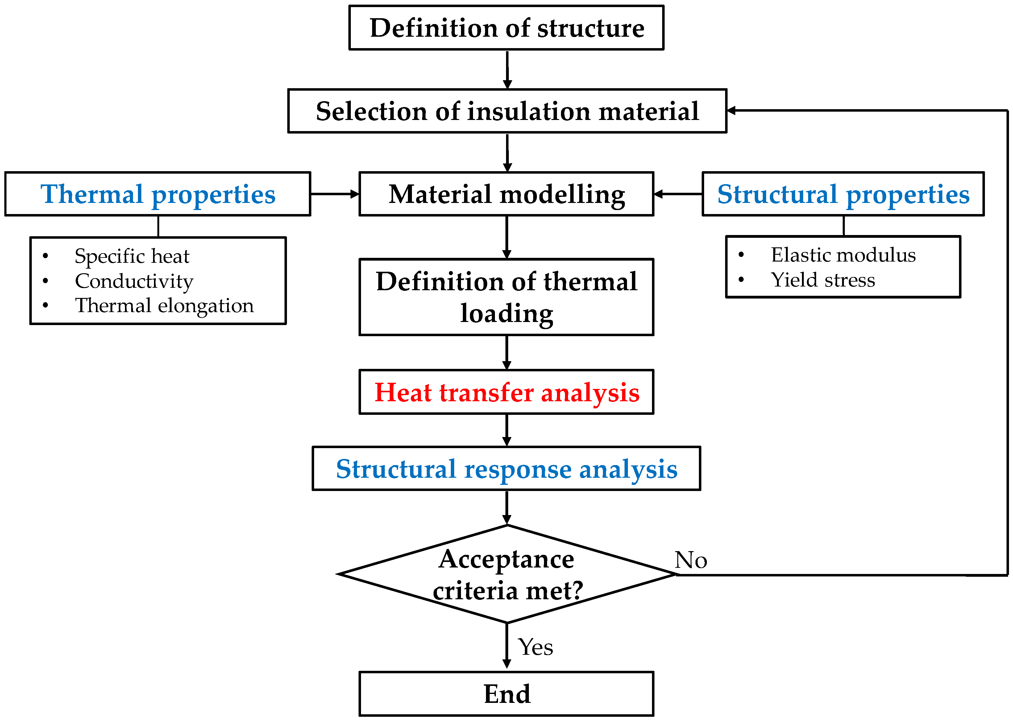
2. Thermal-Structural Analysis Procedure for a Multi-Layer Vacuum Insulation Pipeline
2.1. Thermal-Structural Analysis Procedure
2.2. Multi-Layer Vacuum Insulation Pipeline
3. Mechanical Properties of Steel at Cryogenic Temperature
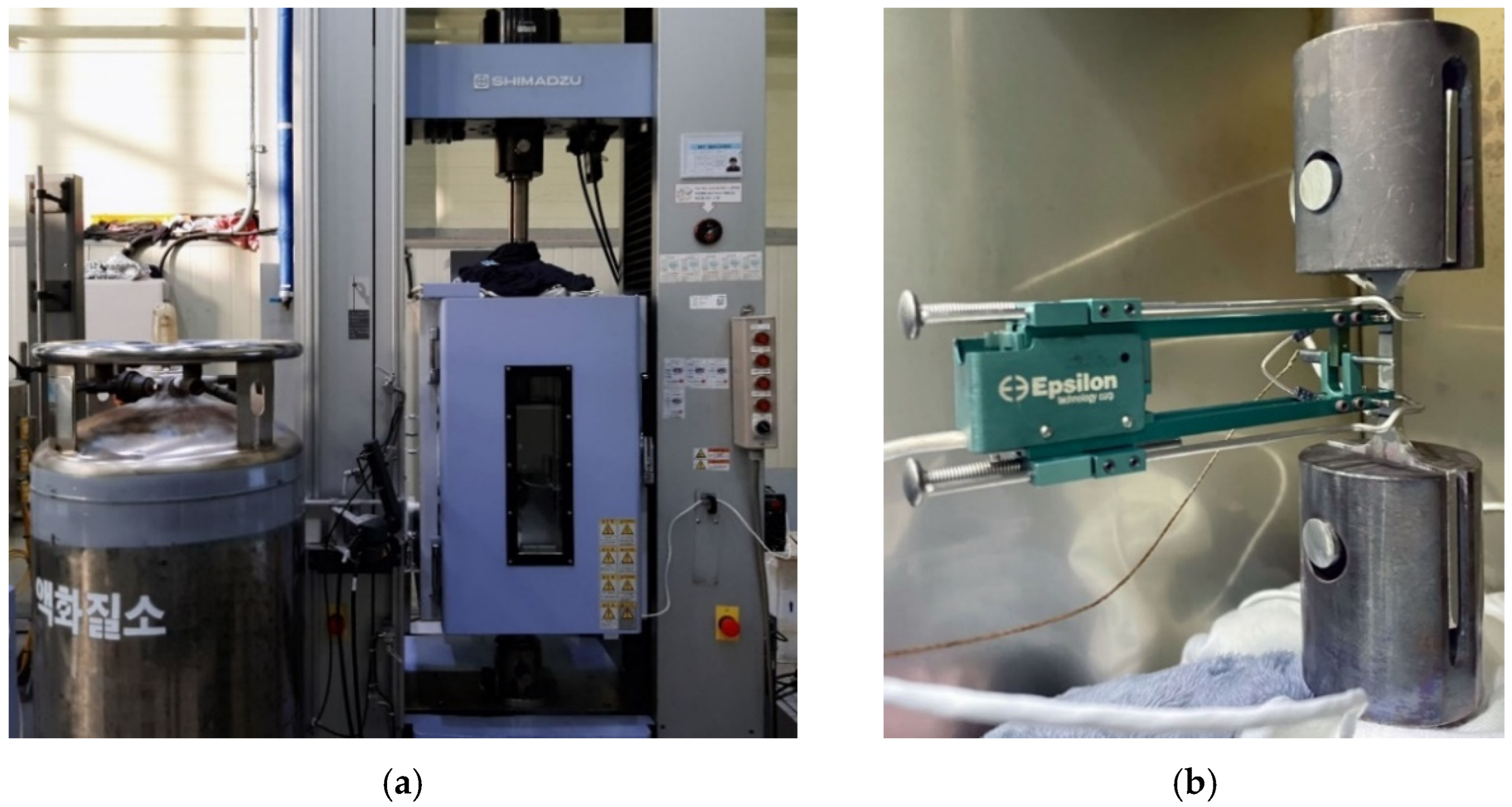
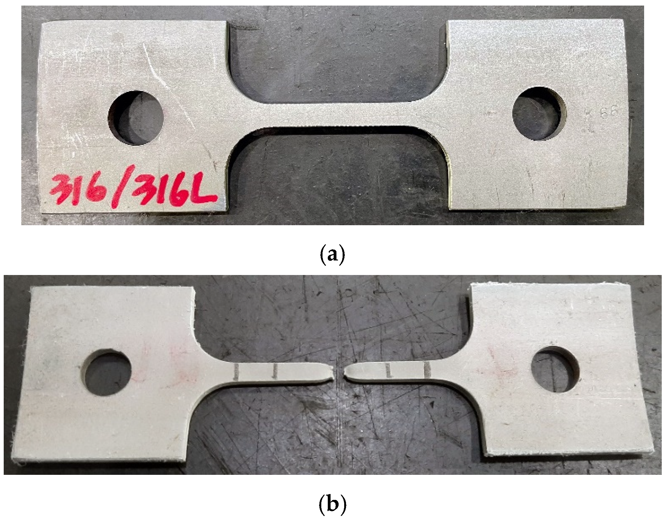
3.1. Experimental Apparatus and Specimen Description
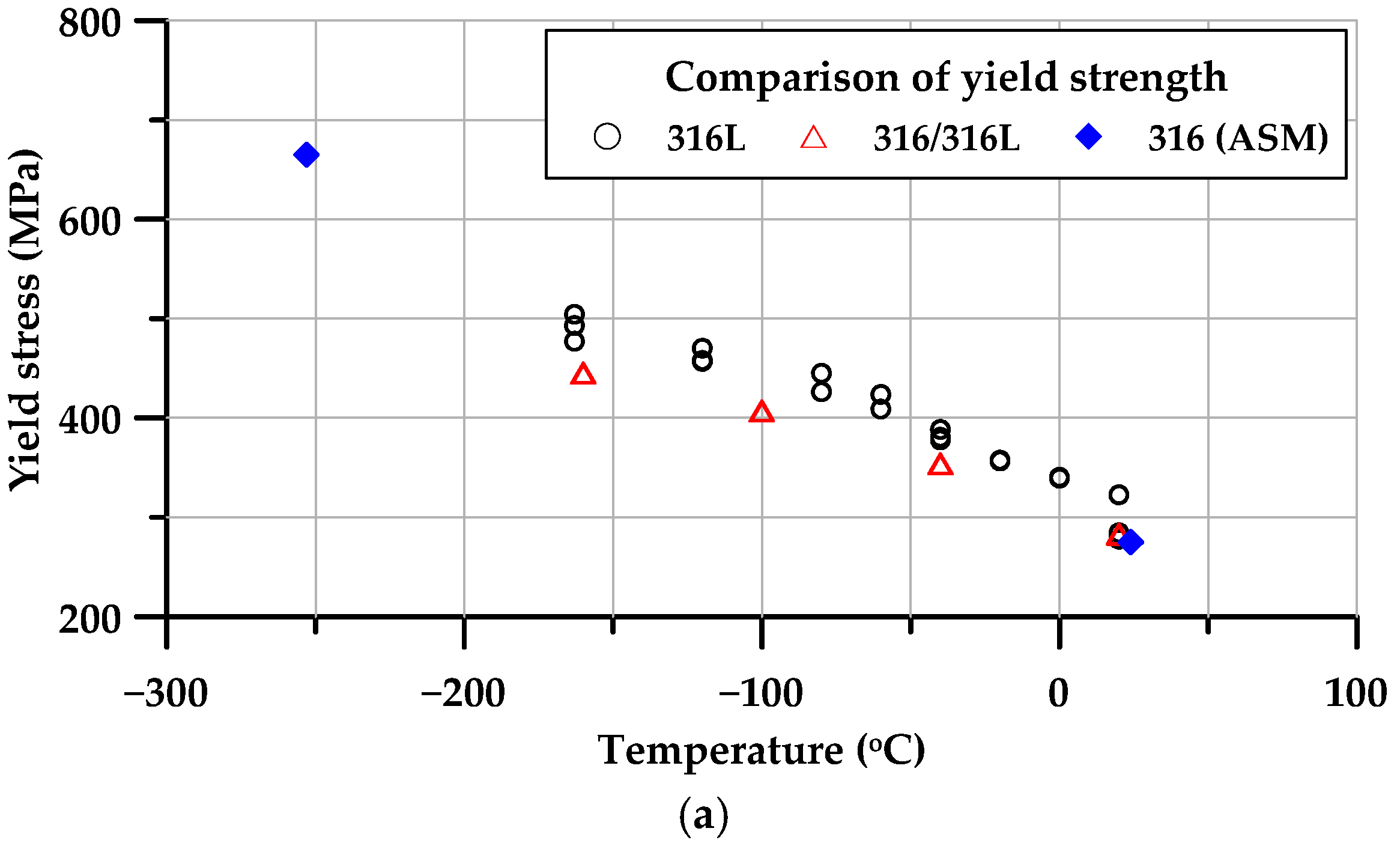
3.2. Experimental Results
3.3. Material Model
4. Numerical Investigation
4.1. Heat-Transfer Analysis under Cryogenic Conditions
4.1.1. Modelling of Heat Transfer Analysis
4.1.2. Analysis Procedure
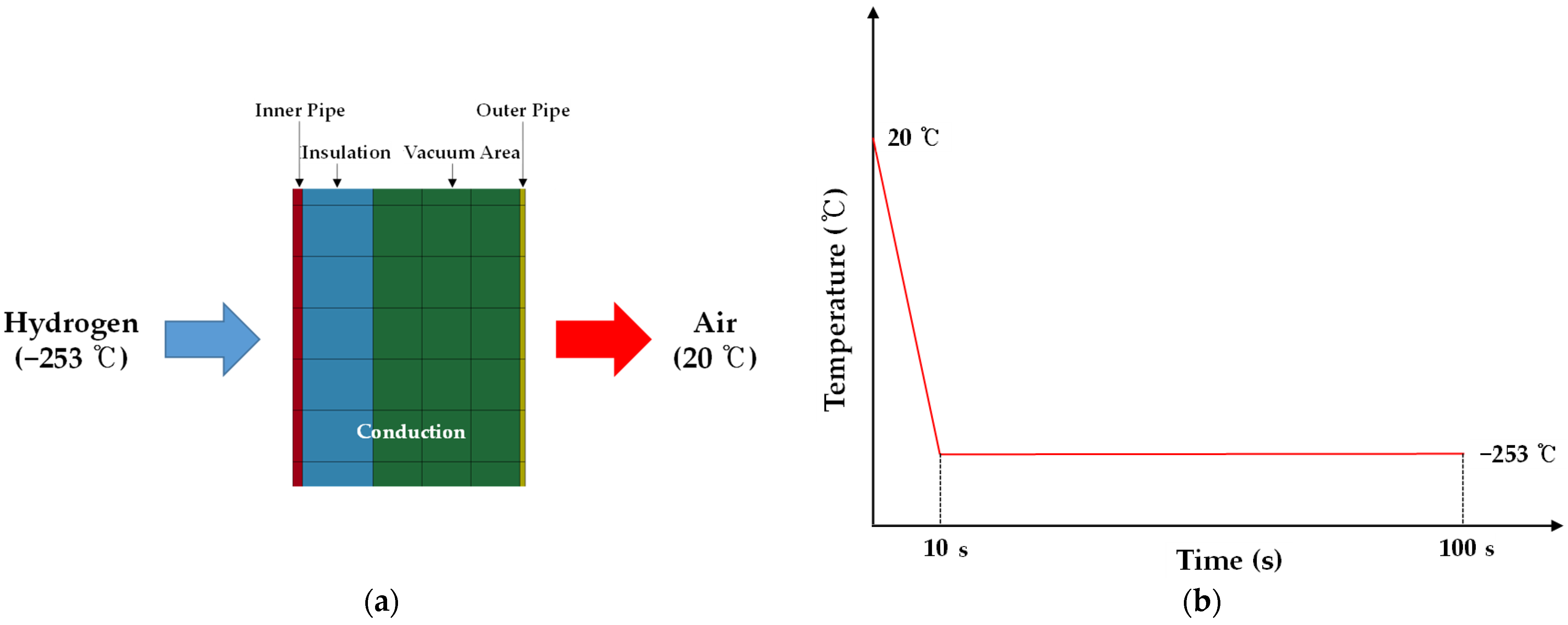
- Heat transfer between LH2 and the inner pipe: it was assumed that the surface of the inner pipe in contact with LH2 had the same temperature as the LH2.
- Heat transfer between the inner pipes: the temperature was calculated according to the thickness of pipe and the insulation, using the thermal conductivity coefficient of the pipe and the insulation.
- Heat transfer between the outer pipe and the external environment (ambient temperature): it was assumed that the surface of the outer pipe in contact with the external environment had the same temperature as the ambient air.
4.1.3. Results of Heat Transfer Analysis
4.2. Structural Response Analysis under Cryogenic Conditions
4.2.1. Methodology of Structural Response Analysis
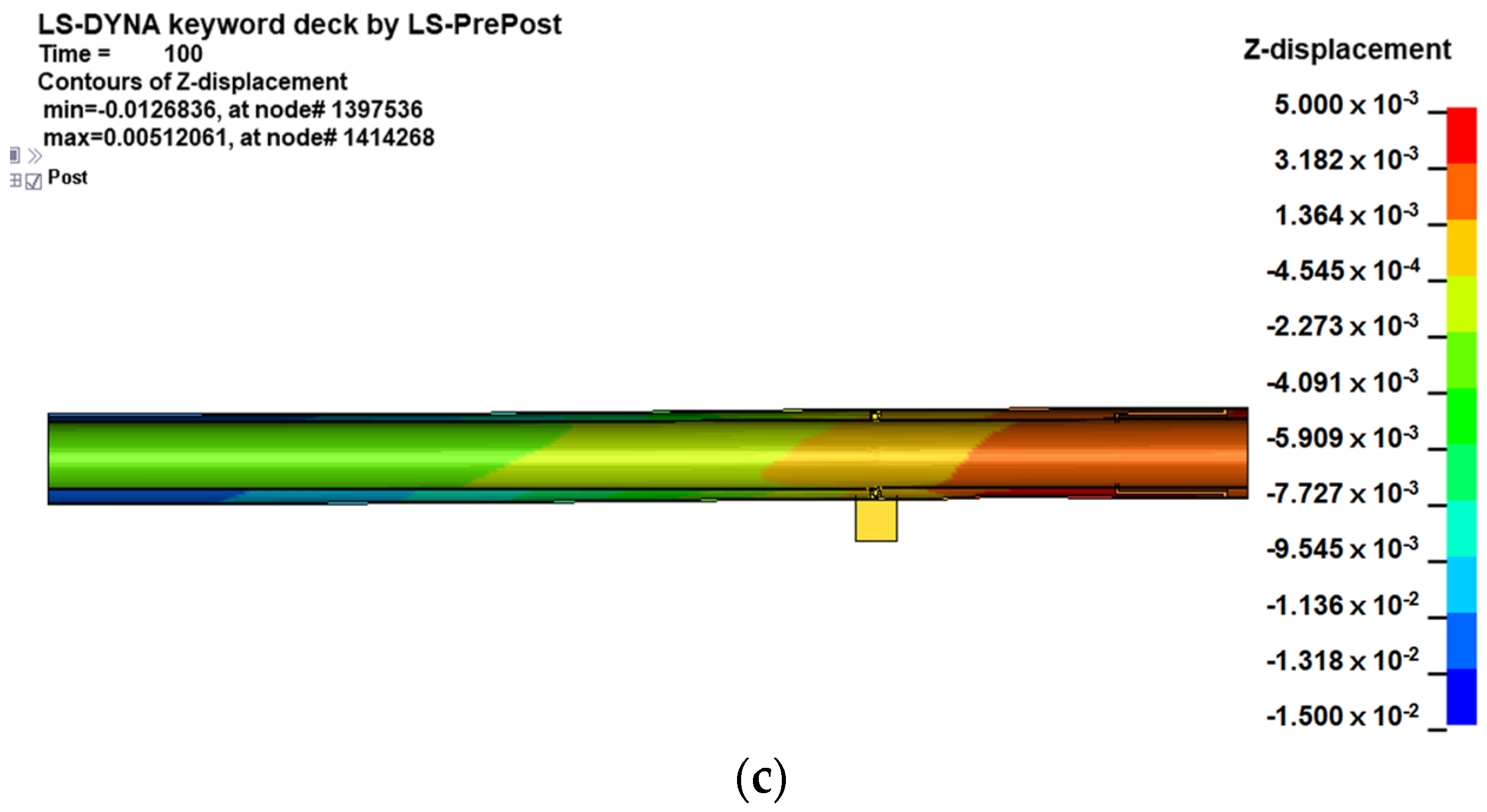
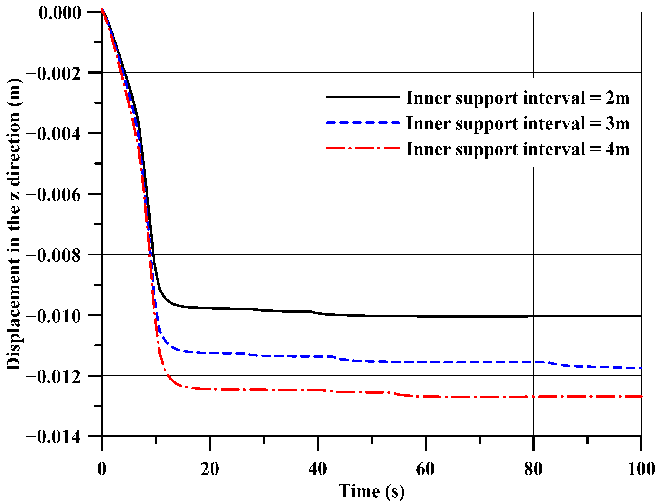
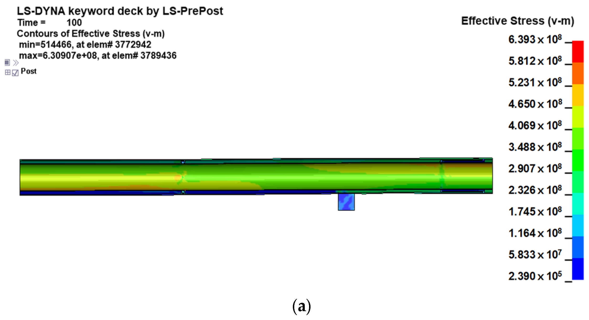
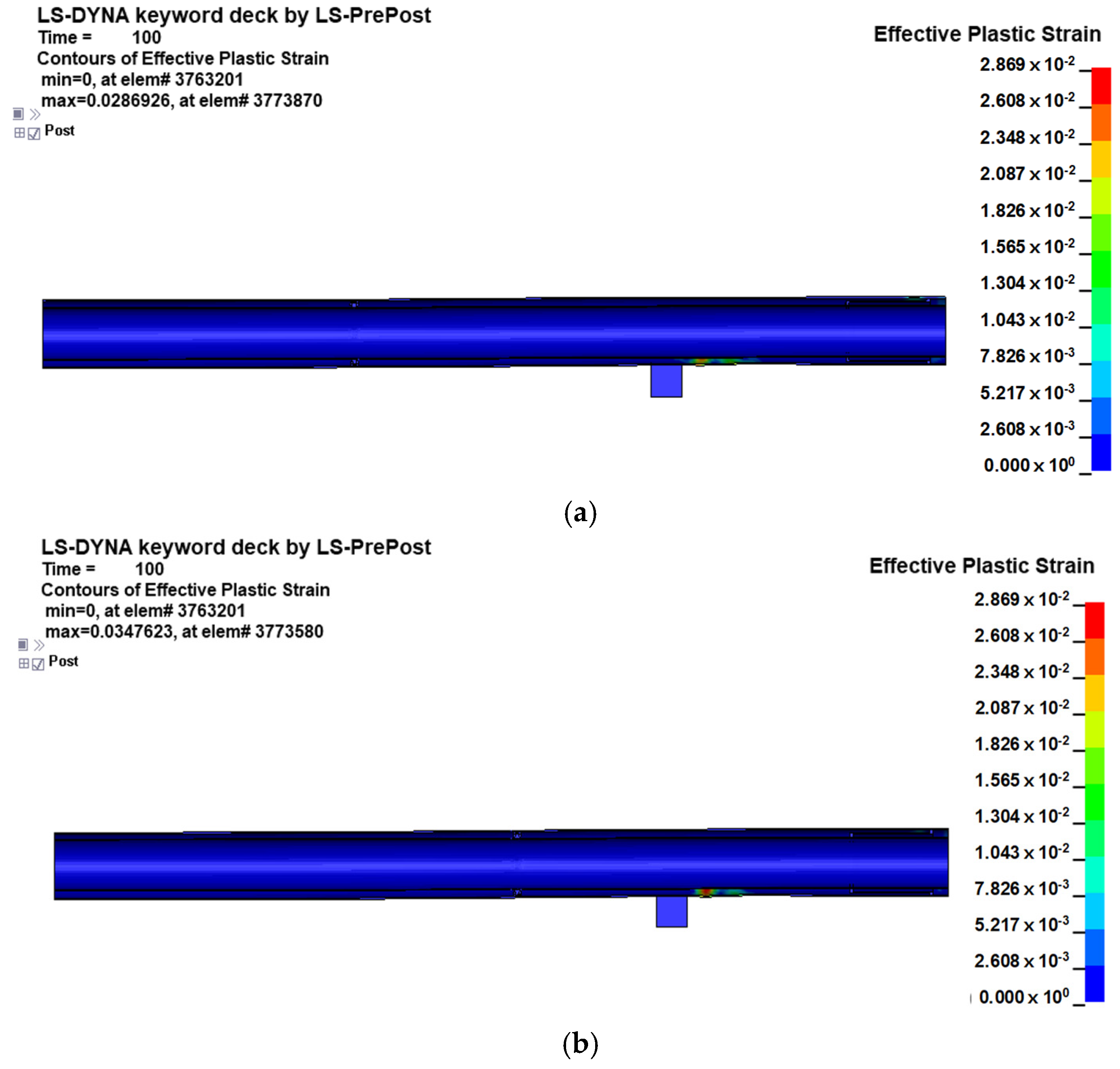
4.2.2. Results of Structural Response Analysis
5. Conclusions
- Thermal-structural design analysis methods were applied for examining an MVIP in an LH2 fuel-supply system for ships. These analysis methods can be useful for the design of an MVIP.
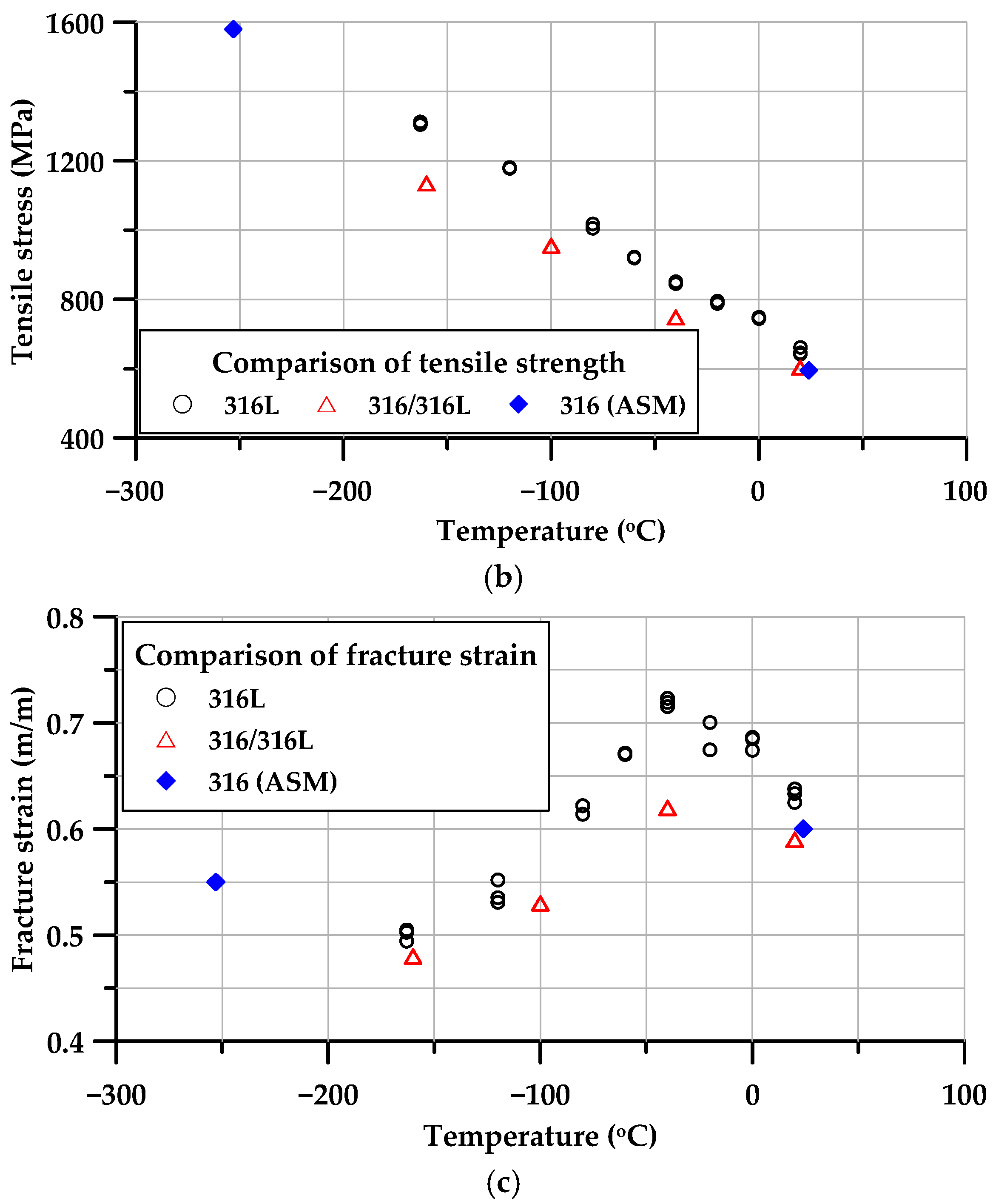
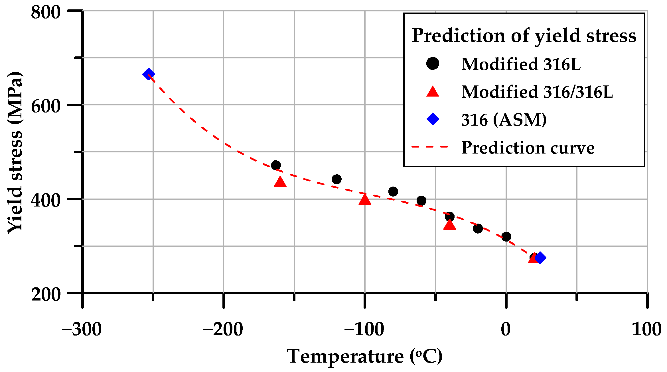
- A series of tensile tests was conducted at various temperatures, encompassing room and cryogenic temperatures, to understand the mechanical characteristics of the target materials. From the results, a formula for yield-stress curve prediction was derived, incorporating a modified yield stress vs. temperature relationship.
- When performing heat transfer and structural response analyses of MVIPs, the dependence of thermal and mechanical properties on cryogenic temperatures should be considered. In this study, the mechanical properties obtained through tensile tests were used.
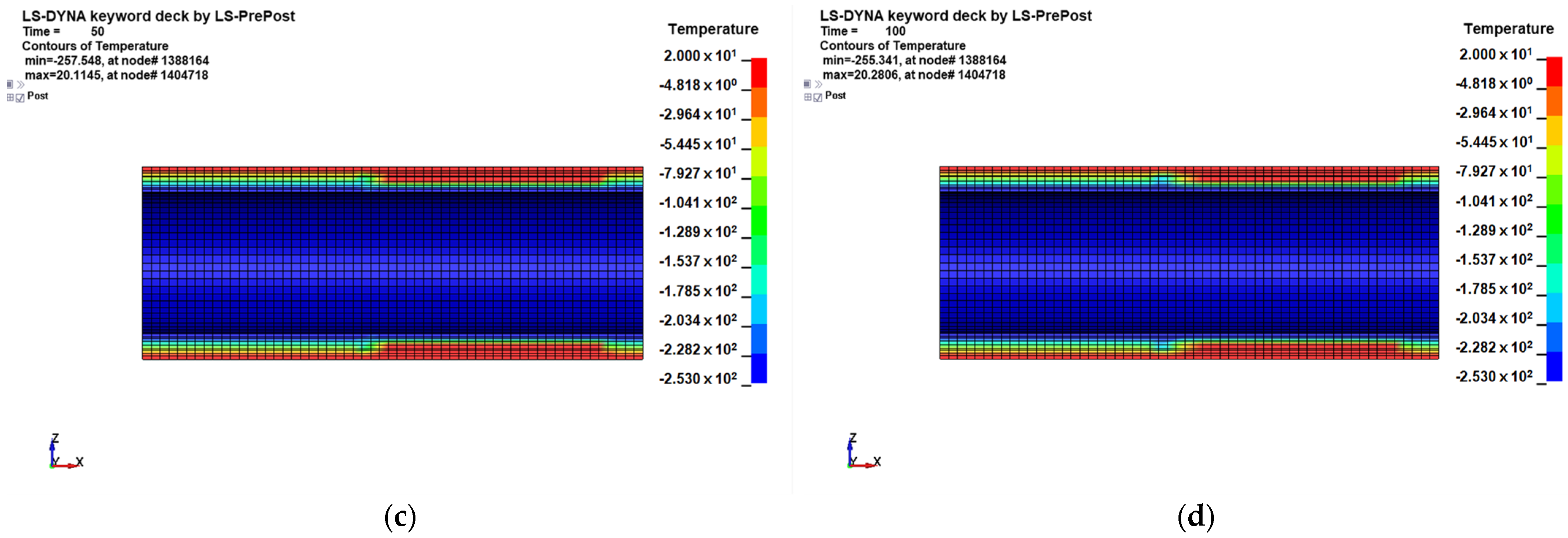
- The results of heat transfer analysis confirmed that heat is transmitted through the inner supporting member, and the insulation of the inner supporting member should be considered in the pipe design.
Author Contributions
Funding
Institutional Review Board Statement
Informed Consent Statement
Data Availability Statement
Conflicts of Interest
References
- Brewer, G.D. LH2 Airport Requirements Study; Lockheed: Burbank, CA, USA, 1976. [Google Scholar]
- Gretz, J.; Baselt, J.P.; Ullmann, O.; Wendt, H. The 100 MW Euro-Quebec hydro-hydrogen pilot project. Int. J. Hydrogen Energy 1990, 15, 419–424. [Google Scholar]
- Kamiya, S.; Nishimura, M.; Harada, E. Study on introduction of CO2 free energy to Japan with liquid hydrogen. Phys. Procedia 2015, 67, 11–19. [Google Scholar]
- Partridge, J.K. Fractional consumption of liquid hydrogen and liquid oxygen during the space shuttle program. AIP Conf. Proc. 2012, 1434, 1765–1770. [Google Scholar]
- Lyea, L.C.; Adama, N.M.; Ahmad, K.A. Cryogenic pipe flow simulation for liquid nitrogen with vacuum insulated pipe (VIP) and polyurethane (PU) foam insulation under steady-state conditions. Therm. Sci. Eng. Prog. 2018, 7, 302–310. [Google Scholar]
- Timmerhaus, K.D. Cryogenic Engineering: Fifty Years of Progress; Springer: New York, NY, USA, 2007; pp. 120–133. [Google Scholar]
- Chorowski, M.; Polinski, J. Modeling of multilayer vacuum insulation—Complexity versus accuracy. In Proceedings of the Twentieth International Cryogenic Engineering Conference (ICEC20), Beijing, China, 11–14 May 2004; pp. 793–796. [Google Scholar]
- Krishnamurthy, M.; Chandra, R.; Jacob, S.; Kasthurirengan, S.; Karunanithi, R. Experimental studies on cool-down and mass flow characteristics of a demountable liquid nitrogen transfer line. Cryogenics 1996, 36, 435–441. [Google Scholar]
- JUNG-WOO ENE Co., Ltd. Available online: https://fgss.co.kr/ (accessed on 27 December 2021).
- ISO/Technical Comittee 164/SC 1; Metallic Materials—Tensile Testing—Part 1: Method of Test at Room Temperature EN ISO 6892-1:2019. International Organization for Standardization: Geneva, Switzerland, 2019.
- ISO/Technical Comittee 164/SC 1; Metallic Materials—Tensile Testing—Part 3: Method of Test at Low Temperature EN ISO 6892-3:2015. International Organization for Standardization: Geneva, Switzerland, 2015.
- JIS G4305:2012; Cold-rolled Stainless Steel Plate, Sheet and Strip. Japanese Standards Association (JISC): Tokyo, Japan, 2012.
- American Society for Testing and Materials (ASTM) International. Standard Specification for Welded Large Diameter Austenitic Steel Pipe for Corrosive or High-Temperature Service. ASTM A409/A409M-19. In Annual Book of ASTM Standards; ASTM International: West Conshohocken, PA, USA, 2019. [Google Scholar]
- Fultz, B.S. The Challenges of LNG Materials Selection. In Proceedings of the Annual Conference of the Australasian Corrosion Association 2014: Corrosion and Prevention, Darwin, Australia, 21–24 September 2014; pp. 1–14. [Google Scholar]
- Davis, J.R. (Ed.) Stainless Steels; ASM International: Almere, The Netherlands, 2010. [Google Scholar]
- Hallquist, J.O. LS-DYNA Keyword User’s Manual; Livermore Software Technology Corporation R11: Livermore, CA, USA, 2021. [Google Scholar]



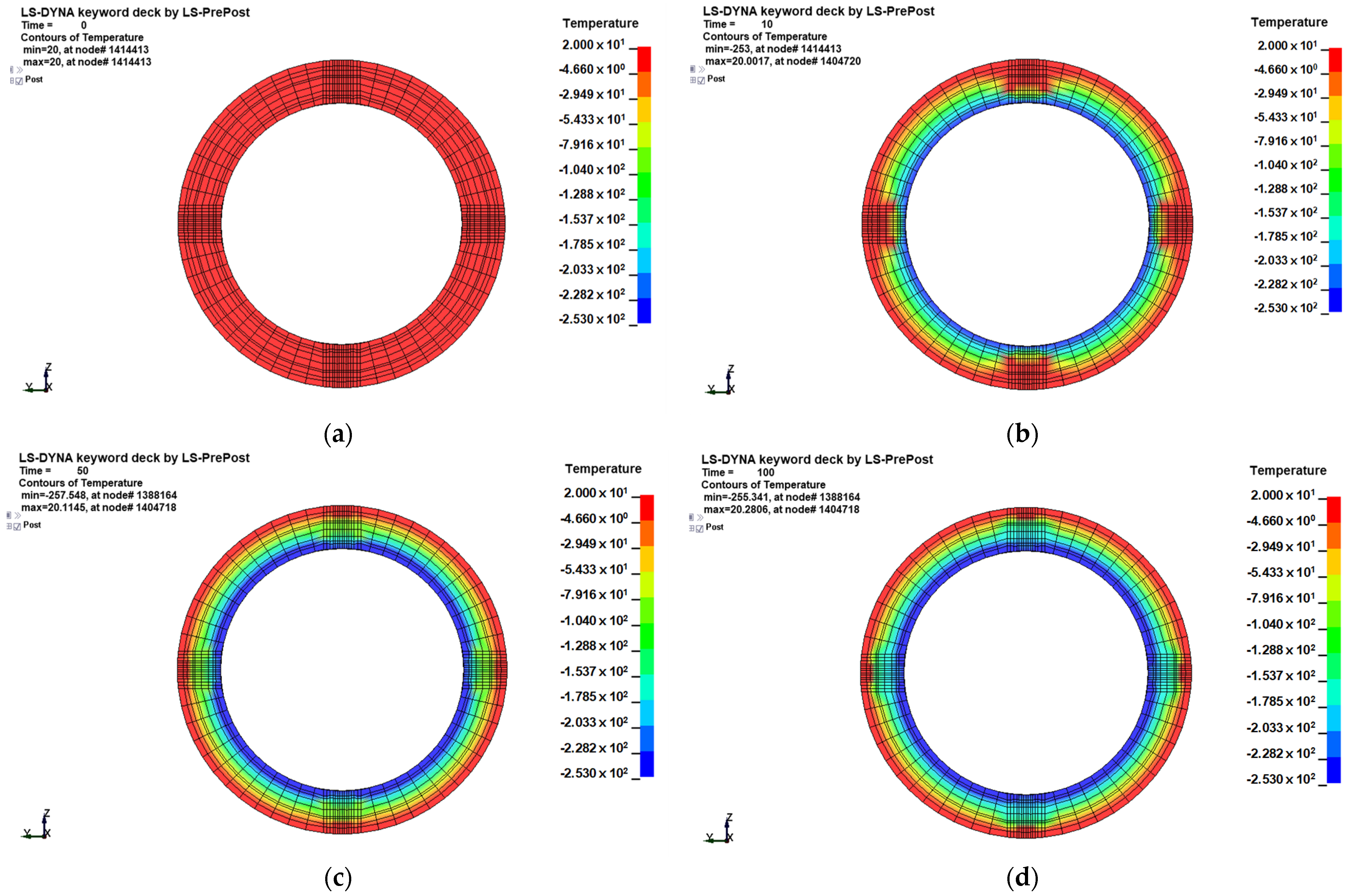


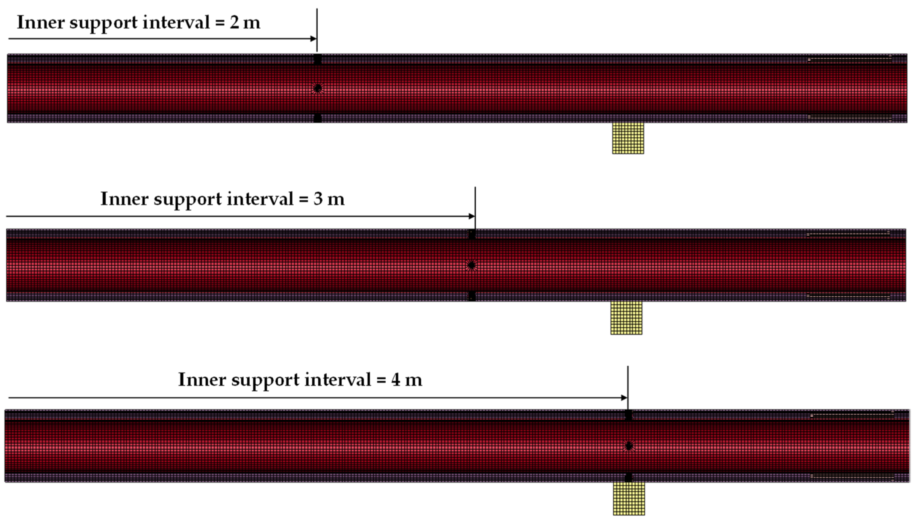
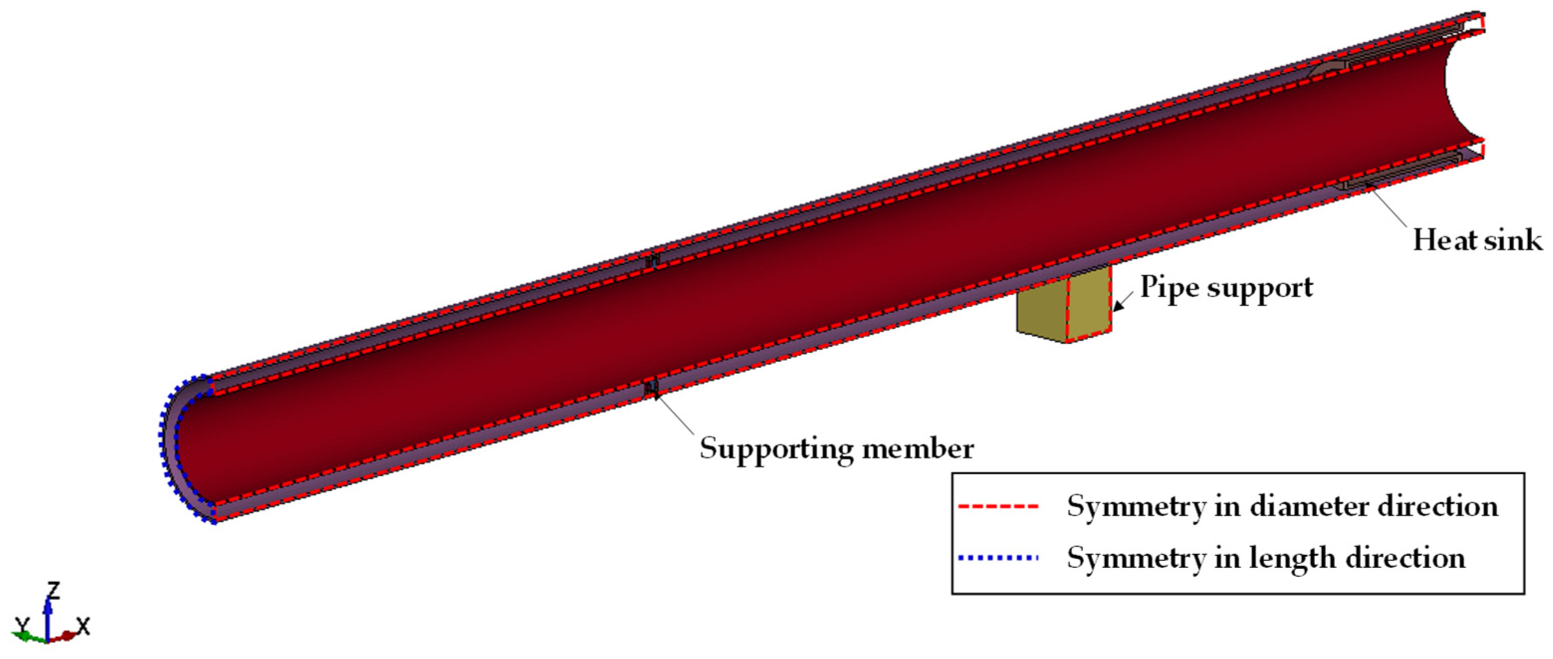
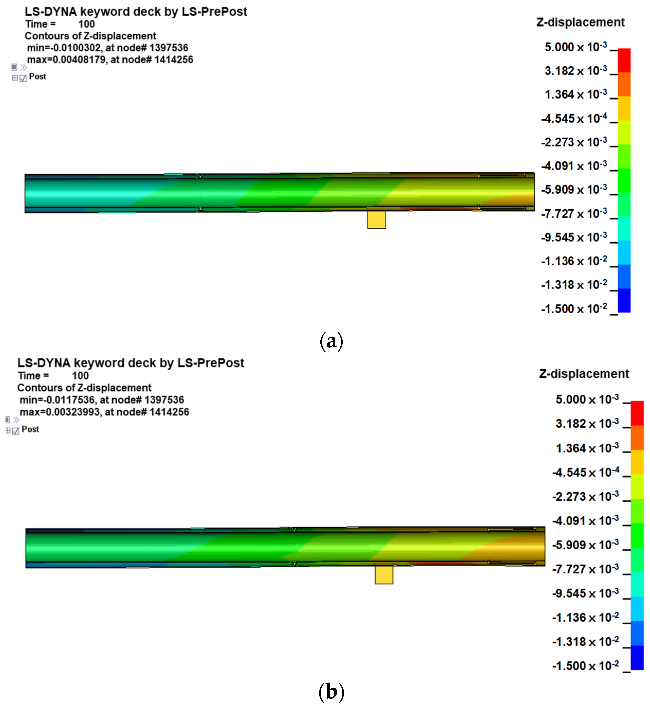

| Type | Thickness from Inner Plate on Inner Pipe (mm) |
|---|---|
| Inner pipe | 3.44 |
| Insulation | 1.82 |
| Vacuum | 19.43 |
| Outer pipe | 4.19 |
| Material | Standard | Base Member | Width (mm) | Thickness (mm) | Gauge Length (mm) |
|---|---|---|---|---|---|
| 316L | JIS G4305 [12] | Sheet | 25 | 1.25 | 50 |
| 316/316L | ASTM A409M [13] | Pipe (4″ 10 S) (ASME 36.16 M) | 6 | 3.05 | 25 |
| Material | C Max. | Mn Max. | P Max. | S Max. | Si Max. | Ni | Cr | Mo | Standard |
|---|---|---|---|---|---|---|---|---|---|
| SUS316 | 0.08 | 2.00 | 0.045 | 0.030 | 1.00 | 10.0 | 16.0~18.0 | 2.00~3.00 | JIS G4305 [12] |
| TP316 | ~14.0 | ASTM A409M [13] | |||||||
| SUS316L | 0.030 | 12.0 | JIS G4305 [12] | ||||||
| ~15.0 | |||||||||
| TP316L | 0.035 | 10.0 | ASTM A409M [13] | ||||||
| ~14.0 |
| Material (Source) | Temperature (°C) | Yield Stress (MPa) | Tensile Stress (MPa) | Fracture Strain (m/m) | |
|---|---|---|---|---|---|
| Actual | Modified | ||||
| 316L | 20 | 278 | 275 | 642 | 0.64 |
| 284 | 646 | 0.63 | |||
| 323 | 661 | 0.63 | |||
| 0 | 339 | 320 | 749 | 0.68 | |
| 340 | 744 | 0.67 | |||
| 340 | 745 | 0.69 | |||
| −20 | 358 | 337 | 795 | 0.70 | |
| 357 | 788 | 0.67 | |||
| −40 | 378 | 362 | 849 | 0.72 | |
| 381 | 845 | 0.72 | |||
| 388 | 851 | 0.72 | |||
| −60 | 409 | 396 | 919 | 0.67 | |
| 424 | 922 | 0.67 | |||
| −80 | 445 | 416 | 1018 | 0.61 | |
| 426 | 1005 | 0.62 | |||
| −120 | 457 | 442 | 1178 | 0.55 | |
| 470 | 1181 | 0.53 | |||
| 458 | 1179 | 0.54 | |||
| −163 | 477 | 472 | 1307 | 0.50 | |
| 504 | 1312 | 0.50 | |||
| 493 | 1305 | 0.49 | |||
| 316/316L | 20 | 283 | 275 | 603 | 0.59 |
| −40 | 354 | 346 | 748 | 0.62 | |
| −100 | 407 | 399 | 955 | 0.53 | |
| −160 | 445 | 437 | 1135 | 0.48 | |
| 316 (ASM) | 24 | 275 | 595 | 0.60 | |
| −253 | 665 | 1580 | 0.55 | ||
| Type | Specific Heat (J/kg·K) | Thermal Conductivity (W/mK) | Thermal Expansion Coefficient |
|---|---|---|---|
| Pipe (TP316L) | 500 | 14.6 | 1.28 × 10⁻⁵ |
| MLI film | 800 | 0.000135 | - |
| Vacuum | 1006 | 0.0001 | - |
| Heat sink (SUS F304) | 500 | 14.6 | 1.37 × 10⁻⁵ |
| Support cap (FRP) | 787 | 1.1 | 3.53 × 10⁻⁵ |
| Part | Description * |
|---|---|
| Bottom surface of pipe support | Ux, Uy, Uz = 1 and Rx, Ry, Rz = 0 |
| Edges in the y-direction | Uy = 1 and Ux, Uz, Rx, Ry, Rz = 0 |
| Edges in the x-direction | Ux = 1 and Uy, Uz, Rx, Ry, Rz = 0 |
| Component | Temperature (°C) | Density (kg/m3) | Elastic Modulus (MPa) | Yield Stress (from Equation (1)) (MPa) | Poisson’s Ratio |
|---|---|---|---|---|---|
| Pipe (TP316L) | 20 | 7900 | 19,300 | 275 | 0.3 |
| 0 | 315 | ||||
| −40 | 368 | ||||
| −80 | 400 | ||||
| −120 | 426 | ||||
| −160 | 462 | ||||
| −210 | 543 | ||||
| −260 | 694 | ||||
| Heat sink (SUS F304) | 20 | 7900 | 19,300 | 295 | 0.3 |
| Support cap | 20 | 2560 | 6890 | 331 | 0.276 |
| Inner Support Interval | Maximum Value | ||
|---|---|---|---|
| Deflection (m) | Von Mises Stress (MPa) | Plastic Strain | |
| 2 m | 0.0100 | 631 | 0.0287 |
| 3 m | 0.0118 | 649 | 0.0348 |
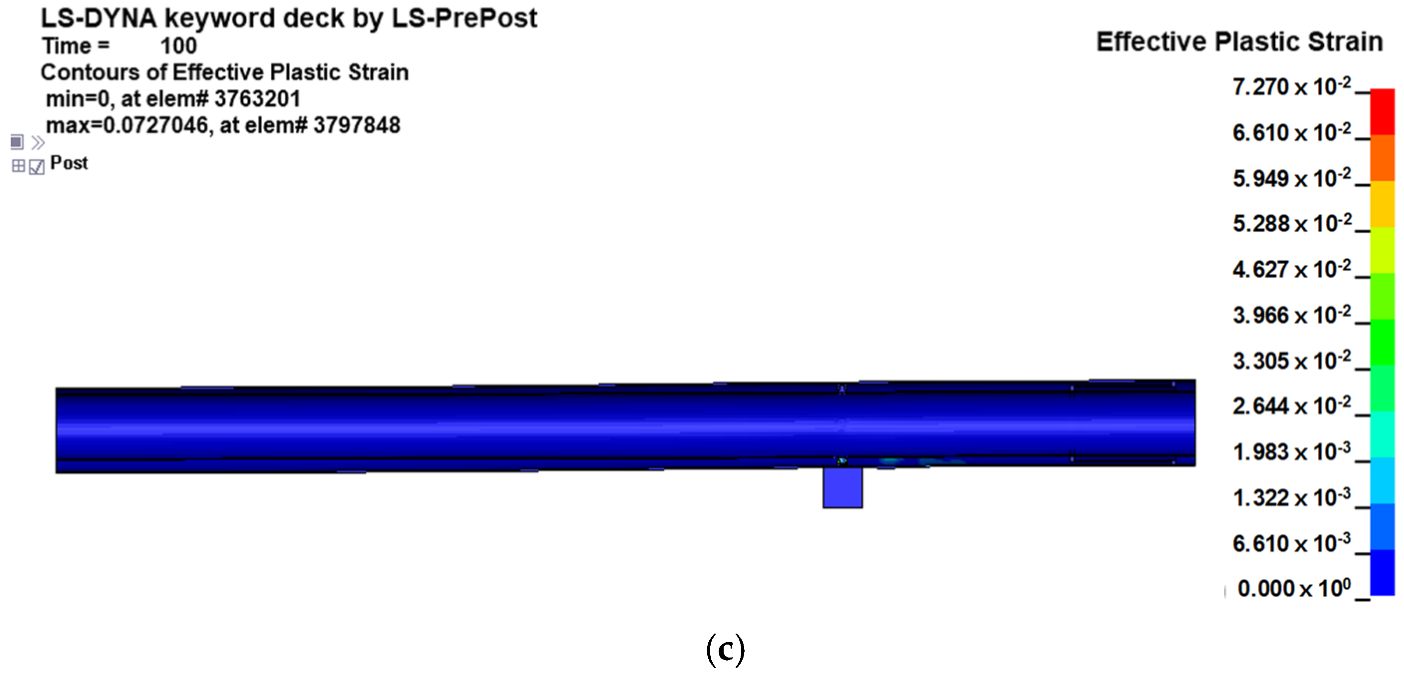
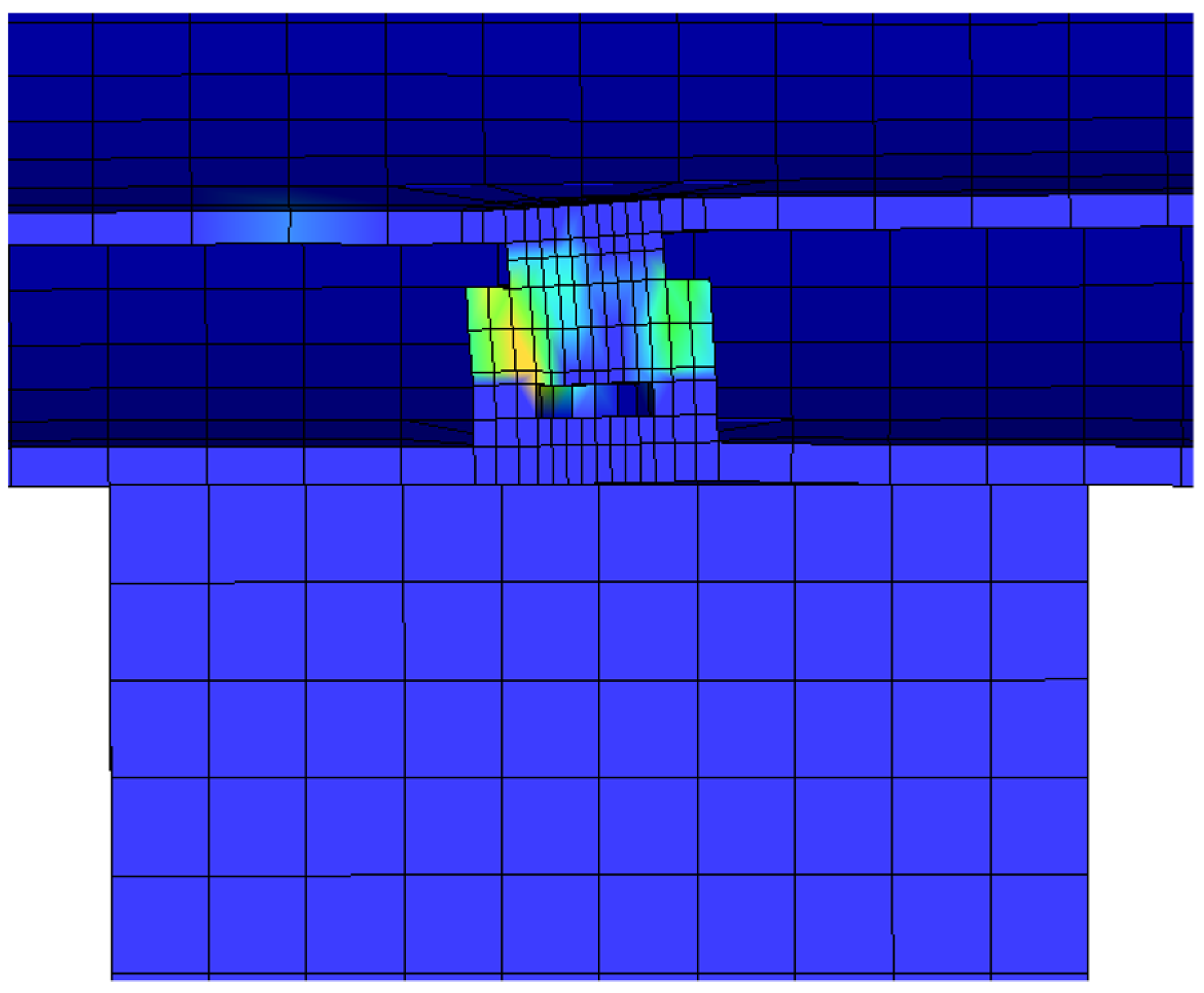
| 4 m | 0.0127 | 639 | 0.0727 |
Publisher’s Note: MDPI stays neutral with regard to jurisdictional claims in published maps and institutional affiliations. |
© 2022 by the authors. Licensee MDPI, Basel, Switzerland. This article is an open access article distributed under the terms and conditions of the Creative Commons Attribution (CC BY) license (https://creativecommons.org/licenses/by/4.0/).
Share and Cite
Kim, J.H.; Park, D.K.; Kim, T.J.; Seo, J.K. Thermal-Structural Characteristics of Multi-Layer Vacuum-Insulated Pipe for the Transfer of Cryogenic Liquid Hydrogen. Metals 2022, 12, 549. https://doi.org/10.3390/met12040549
Kim JH, Park DK, Kim TJ, Seo JK. Thermal-Structural Characteristics of Multi-Layer Vacuum-Insulated Pipe for the Transfer of Cryogenic Liquid Hydrogen. Metals. 2022; 12(4):549. https://doi.org/10.3390/met12040549
Chicago/Turabian StyleKim, Jeong Hwan, Dae Kyeom Park, Tae Jin Kim, and Jung Kwan Seo. 2022. "Thermal-Structural Characteristics of Multi-Layer Vacuum-Insulated Pipe for the Transfer of Cryogenic Liquid Hydrogen" Metals 12, no. 4: 549. https://doi.org/10.3390/met12040549
APA StyleKim, J. H., Park, D. K., Kim, T. J., & Seo, J. K. (2022). Thermal-Structural Characteristics of Multi-Layer Vacuum-Insulated Pipe for the Transfer of Cryogenic Liquid Hydrogen. Metals, 12(4), 549. https://doi.org/10.3390/met12040549


